Article

4-Port MIMO Antenna with Defected Ground Structure for 5G Millimeter Wave Applications

1
ACTSENA Research Group, Department of Telecommunication Engineering, University of Engineering and Technology, Taxila, Punjab 47050, Pakistan
2
Department of Computer and Communication Engineering, Chungbuk National University, Cheongju 28644, Korea
3
Department of Electrical Engineering, Polytechnique Montreal, Montreal, QC H3T 1J4, Canada
4
Department of Mechanical and Industrial Engineering, College of Engineering, Qatar University, P.O. Box 2713 Doha, Qatar
*
Authors to whom correspondence should be addressed.
Submission received: 28 November 2019 / Revised: 16 December 2019 / Accepted: 19 December 2019 / Published: 1 January 2020

Abstract

:
We present a 4-port Multiple-Input-Multiple-Output (MIMO) antenna array operating in the mm-wave band for 5G applications. An identical two-element array excited by the feed network based on a T-junction power combiner/divider is introduced in the reported paper. The array elements are rectangular-shaped slotted patch antennas, while the ground plane is made defected with rectangular, circular, and a zigzag-shaped slotted structure to enhance the radiation characteristics of the antenna. To validate the performance, the MIMO structure is fabricated and measured. The simulated and measured results are in good coherence. The proposed structure can operate in a 25.5–29.6 GHz frequency band supporting the impending mm-wave 5G applications. Moreover, the peak gain attained for the operating frequency band is 8.3 dBi. Additionally, to obtain high isolation between antenna elements, the polarization diversity is employed between the adjacent radiators, resulting in a low Envelope Correlation Coefficient (ECC). Other MIMO performance metrics such as the Channel Capacity Loss (CCL), Mean Effective Gain (MEG), and Diversity gain (DG) of the proposed structure are analyzed, and the results indicate the suitability of the design as a potential contender for imminent mm-wave 5G MIMO applications.

1. Introduction

In the modern era, the eminent increase of wireless devices, inadequate bandwidth, and limited channel capacity have substantially promoted efforts to develop advanced standards for communication networks. Subsequently, this has promoted the development of next-generation (5G) communication systems at the mm-wave spectrum featuring much greater channel capacity and higher data rates [1,2]. The forthcoming 5G technology not only provides greatly increased reliability, high data rate requirements, and low power consumption to meet the massive increase in linked devices, but also promises to increase the prospects of emerging technologies such as virtual reality and smart cities [3,4,5]. However, critical limitations at the mm-wave spectrum, such as signal fading, atmospheric absorptions, and path loss attenuations need to be resolved, which becomes more significant with the usage of the single antenna [6,7,8]. Multiple-input multiple-output (MIMO) antenna has been determined to be a key enabling technology for current and future wireless systems, demonstrating concurrent operation of multi-antennas, increasing channel capacity along with the benefits of high data rates and throughput of Gigabits/sec [9,10,11]. The 5th generation MIMO antenna requires high bandwidth for concurrent functioning, while the high gain is required to reduce the atmospheric diminutions and absorptions at mm-wave frequencies, and compactness of structure is needed to facilitate the assimilation in MIMO systems. In addition to this, the challenges associated with MIMO antenna designing are to design closely packed antenna elements with reduced mutual coupling and high isolation, which subsequently improves the antenna performance.
Recently, several antenna solutions operating at mm-wave bands for 5G applications have been reported in the literature [12,13,14,15,16,17,18,19,20,21,22,23,24,25,26,27,28,29,30,31,32,33,34,35]. The antenna designs operating at the potential mm-wave bands with low gain reference [12,13,14] are not proficient enough to deal with the high atmospheric and propagation losses at the mm-wave frequency. In order to mitigate these attenuation effects, several high gain and beam-steering antenna array solutions have been presented to have strong signal strength and to offer large spatial coverage [15,16,17,18,19,20,21,22,23].
However, multi-element antenna arrays exhibit the same capacity as the single antenna because the antenna arrays are likewise fed with a single port. Conversely, MIMO antennas demonstrate multipath propagation with a higher data rate, increased capacity, and link reliability, which are the main features of 5G. A number of MIMO antenna designs for 5G mm-wave applications have been reported recently in the literature [24,25,26,27,28,29,30,31,32,33,34,35]. A PIFA array with MIMO configuration with 1 GHz operational bandwidth and a peak simulated gain as 12 dBi is reported in reference [24]. An EBG based mm-wave MIMO antenna is reported in reference [25] with a bandwidth of 0.8 GHz. The multi-element antenna design proposed in reference [26] enables the radiation to bend toward an intended inclined direction, which is suitable for 5G communications. A bandwidth of 1.5 GHz ranging from 27.2 GHz to 28.7 GHz is obtained, whereas the maximum gain attained by the antenna geometry is 7.41 dBi at 28 GHz. DRA based antennas for 5G applications are reported in references [27,28], having a limited data rate of approximately 1 GHz. In reference [27], the SIW feeding technique is reported with a peak gain of 7.37. To ensure MIMO performance, ECC is also evaluated in reference [28]. Likewise, a SIW fed slotted MIMO antenna array for mm-wave communication is reported in reference [29]. The proposed antenna covers the 24.25–27.5 GHz, and the 27.5–28.35 GHz bands for 5G, while the gain varies from 8.2 to 9.6 dBi over the operating frequency range. Moreover, a four-element T-shaped MIMO antenna with overall dimensions of 12 × 50.8 × 0.8 mm3 is presented for 5G applications [30]. The partial ground at the bottom layer consists of iteratively placed symmetrical split-ring slots. The proposed antenna design is covering a wide bandwidth of 25.1–37.5 GHz with a peak gain of 10.6 dBi. However, only ECC as the MIMO performance metric is investigated in this work. In another article, an 8 × 8 MIMO antenna design with an overall substrate size of 31.2 × 31.2 × 1.57 mm3 for future 5G devices is demonstrated [31]. The proposed MIMO structure resonates at 25.2 GHz, having a bandwidth of 5.68 GHz at -6 dB reference, while the maximum value of gain attained is 8.732 dB. Additionally, ECC, MEG, and Diversity gain are also examined. Similarly, a two-port MIMO array with overall dimensions of 31.7 × 53 × 0.2 mm3, and excited by microstrip feedline has been reported for 5G communication systems [32]. The reported antenna system with reflectors based on EBG provides a wide bandwidth and high gain of up to 11.5 dB in the operating band. Analysis of ECC and Diversity gain is exhibited for the proposed MIMO configuration. Likewise, in reference [33], a 5G MIMO antenna with three pairs of integrated metamaterial arrays is demonstrated. The overall substrate size is 30 × 30.5 × 0.508 mm3, whereas the maximum gain achieved by the antenna is 7.4 dBi at 26GHz. Moreover, the work in reference [34] presents a Fabry Perot high gain antenna with a superstrate for 5G MIMO applications. The proposed structure covers the mm-wave spectrum ranging from 26–29.5 GHz, with a maximum gain value of 14.1 dBi. In addition, ECC is analyzed to measure the MIMO performance of the proposed antenna configuration. A two-element MIMO dielectric resonator antenna (DRA) is suggested in reference [35]. The reported antenna covers the 27.19–28.48 GHz band for 5G applications. A gain value approaching 10 dB is obtained for the exhibited antenna. Furthermore, ECC, DG, channel capacity, and TARC are also inspected.
The design of a 4-element antenna array with MIMO capabilities at mm-wave 5G frequency bands is demonstrated in this paper. The proposed design is a high gain and wideband antenna with good MIMO characteristics for future 5th generation devices, such as smartwatches and mobile WiFi, etc. The proposed MIMO antenna with a compact and simple geometry facilitates its assimilation into 5G smart devices. The good MIMO performance of reported antenna endorses the appropriateness of the design for future 5G wireless communication applications.

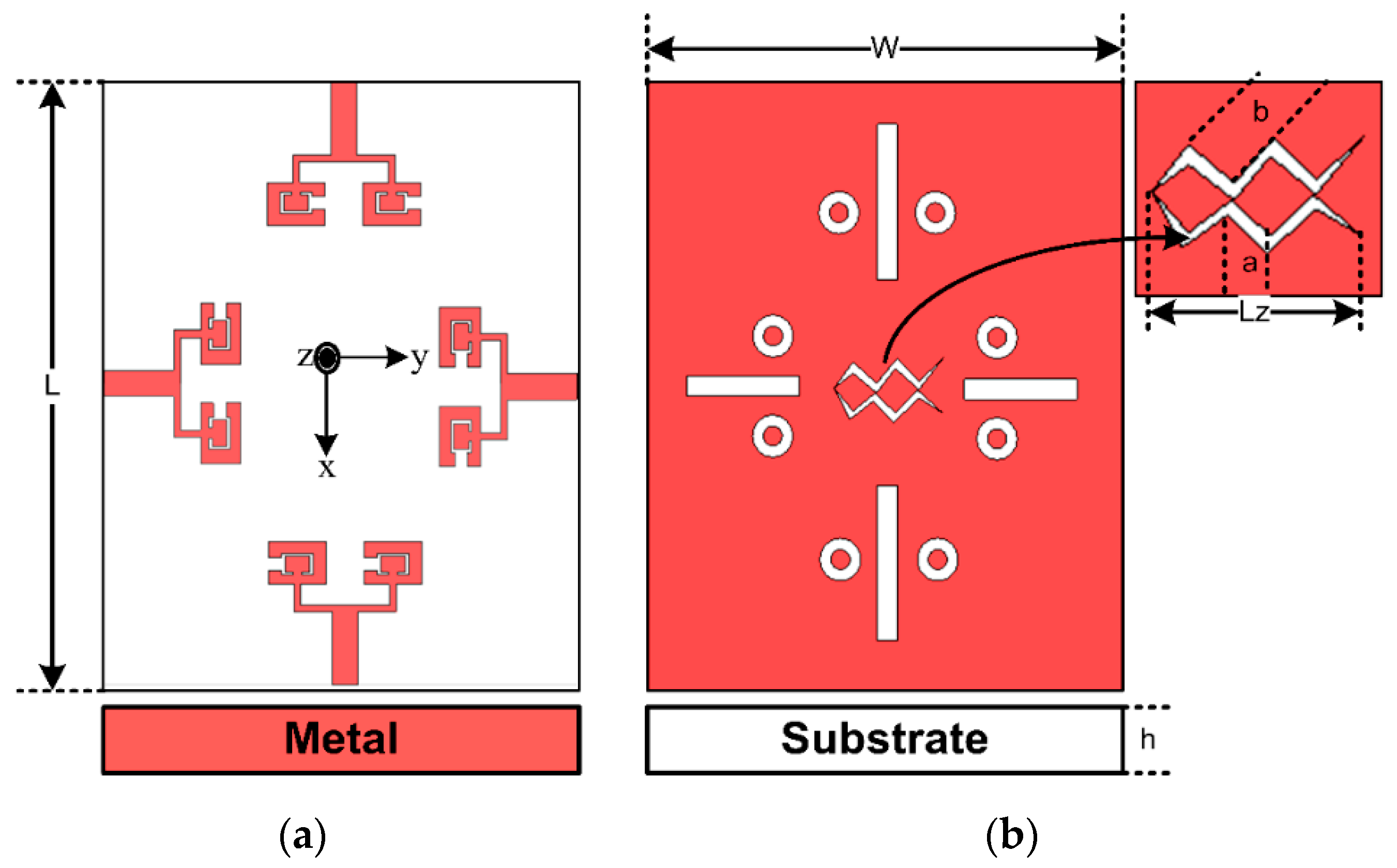
2. Proposed Antenna Design

This work proposes a 4 port MIMO antenna system with overall substrate dimensions of 30 × 35 × 0.76 mm3, as shown in Figure 1. The antenna is modeled and simulated in a commercially available EM simulator CST microwave studio suite.
The reported antenna system comprises of four MIMO elements placed on the center of each edge on the top layer, as shown in Figure 1a. Figure 1b depicts that the layer at the bottom side is composed of a Defected Ground Structure (DGS) with rectangular, circular, and zigzag-shaped slots to further enhance the performance of the proposed design. The design is integrated on the Rogers R04350B substrate with a thickness and permittivity (εr) of 0.76 mm and 3.66, respectively. The dimensional details of the design are provided in Table 1, and the progression of the design from a single element to MIMO configuration is comprehensively discussed in the subsequent sections.

2.1. Single Element Antenna

At first, a single element of the patch antenna is designed as shown in Figure 2a. The primary antenna structure resonating at 28 GHz is obtained by following the well-established mathematical equations provided in references [1,2,3,4]. The optimized single element antenna consists of an inverted C-shaped patch enclosing a rectangular-shaped slit.
W p =   c 2 f c ε r e l a t i v e + 1 2
ε e f f   =   ε r e l a t i v e + 1 2 + ε r e l a t i v e 1 2 ( 1 1 + 12 ( h W p ) )
Δ L = 0.421 h ( ε e f f + 0.3 ) ( W p h + 0.264 ) ( ε e f f 0.258 ) ( W p h + 0.8 )
L p = c 2 f o ε e f f 2 Δ L
where Wp and Lp are the patch’s width and length, h is the height of the substrate, ε e f f and ε r e l a t i v e are the effective permittivity and relative permittivity of substrate respectively. c, fc,, and Δ L are the speed of light, central frequency, and the effective length, respectively.

2.2. Two Element Antenna Array

The design is processed further from a single element to the two-element array, as shown in Figure 2b. The parallel feed network is proposed as the array’s excitation mechanism. The main feed is matched at 50 Ω impedance while the impedance of the branched network is matched at 100 Ω. Afterward, a rectangular and two symmetrically placed circular slots are incorporated in the bottom layer in order to further optimize the obtained results, as illustrated in Figure 2c. Consequently, an enhanced bandwidth and gain are achieved by the reported antenna array. Both elements in the array antenna are separated by λ, which is approximately 11 mm at 28 GHz. Hence a compact array structure with proved performance is achieved.

2.3. MIMO Configuration

After the attainment of the two-element array, the design is progressed further, and the 4-port MIMO antenna system is obtained. Each MIMO element consists of an antenna array obtained previously in this work and is placed at the center positions of the board sides, as shown in Figure 1a. The overall dimensions of the board are 30 × 35 mm2. The MIMO antenna configuration thus obtained exhibits acceptable performance, but to further improve the performance and to reduce mutual coupling among the MIMO antennas, a zigzag-shaped DGS is integrated, as illustrated in Figure 1b. As a result, the isolation for the MIMO configuration is increased.

3. Simulated Results

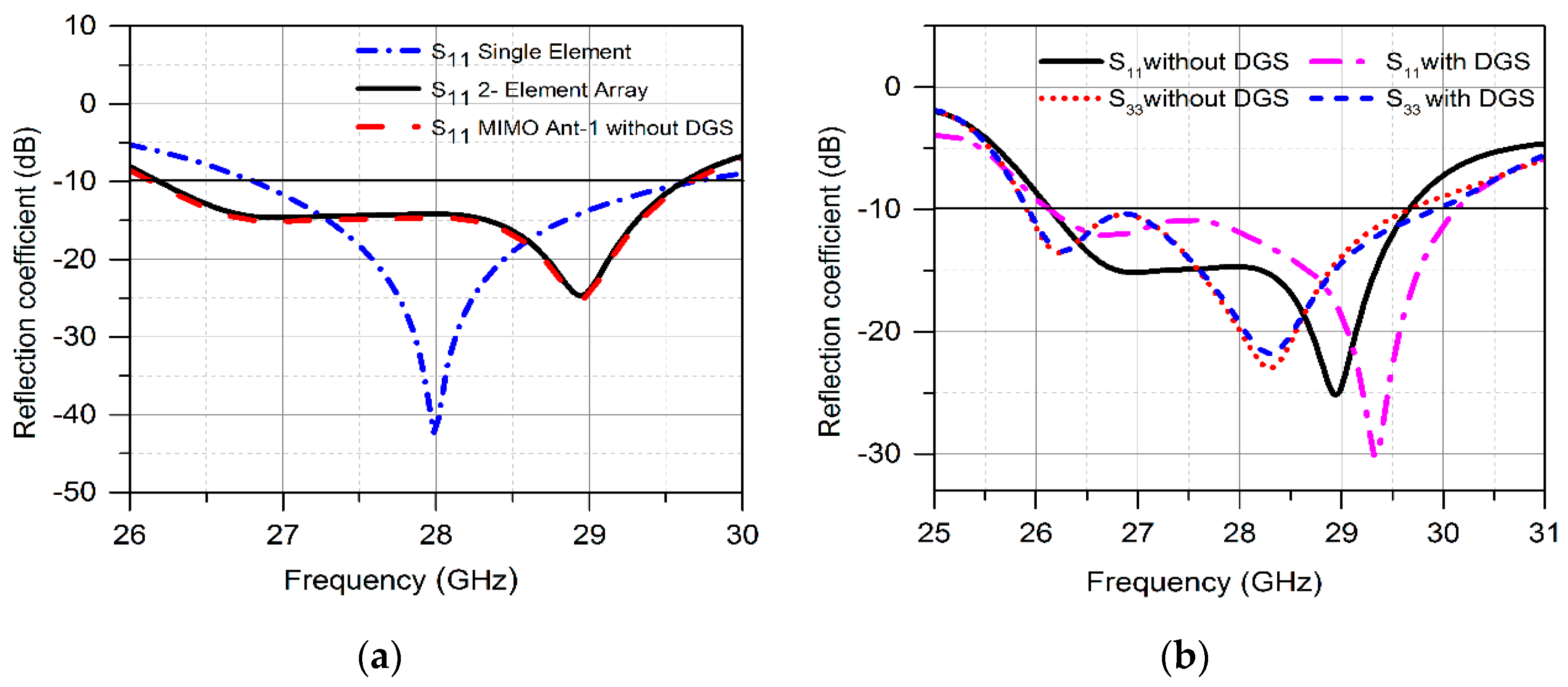
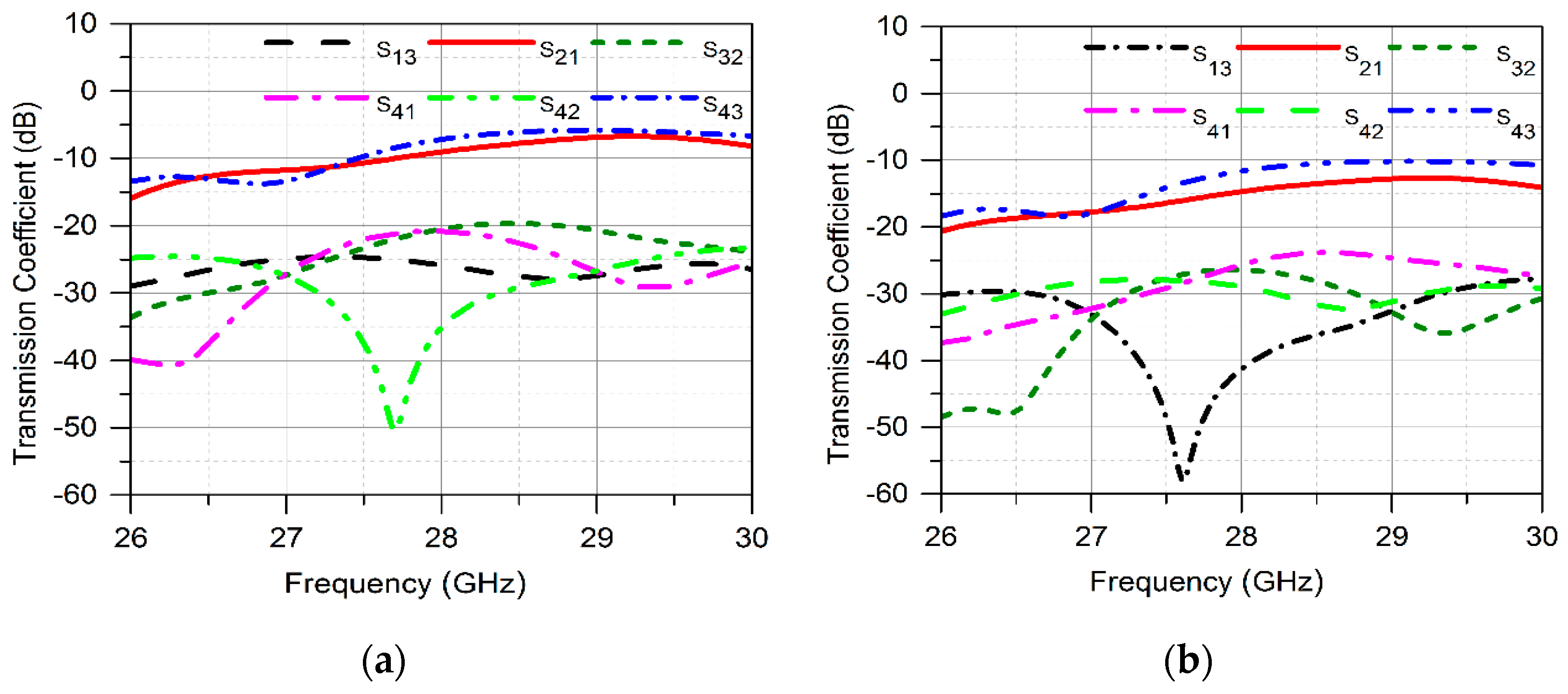
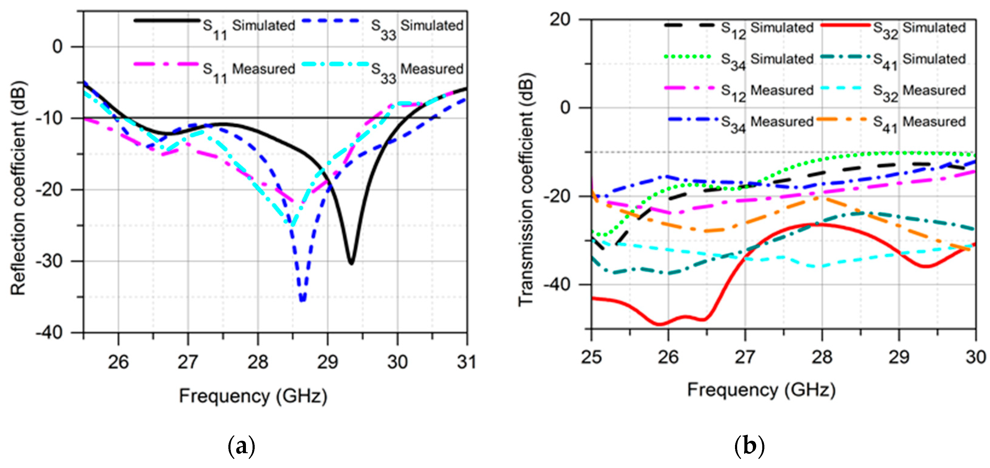
3.1. Scattering Parameters

The working principle and radiation characteristics of the reported antenna system are analyzed. Figure 3a shows the analysis of the reflection coefficient curves of the design from a single element to MIMO configuration. It is observed that the single element of the proposed antenna is resonating in the mm-wave frequency spectrum ranging from 26.8–29.6 GHz with a 2.8 GHz bandwidth. The apparent increase in bandwidth is noticed when the antenna is developed from a single element to two-element arrays. The bandwidth obtained for the antenna array is 3.5 GHz covering the 26.2–29.7 GHz frequency band. Moreover, the reflection coefficient curve of the MIMO Ant.1 in Figure 3a demonstrates that the frequency band covered now ranges from 26.1–29.78 GHz with a slight increase in bandwidth to 3.68 GHz. Furthermore, Figure 3b depicts the reflection coefficient curves for the MIMO Ant1-Ant4 with and without DGS. It is observed that the four MIMO antennas cover nearly the same band. In addition, the bandwidth of the MIMO antennas has improved after the incorporation of DGS. The frequency band now covered by the MIMO antenna system is 26.1–30 GHz with a 3.9 GHz bandwidth.
Figure 4a exhibits the transmission coefficient curves for the four MIMO antennas. It is observed that isolation between antenna 1 and antenna 2 is low. In addition, similar behavior is observed between Ant 3 and Ant 4. Meanwhile, significant isolation is obtained for the antenna pairs 1 and 3, 1and 4, 2 and 3, as well as 2 and 4. A zig-zag shaped DGS is incorporated at the bottom layer of the MIMO antenna structure to reduce mutual coupling effects. Figure 4b validates the isolation enhancement between the MIMO antennas after the assimilation of the DGS. Hence, the minimum isolation obtained for the suggested MIMO antennas is below −10 dB.

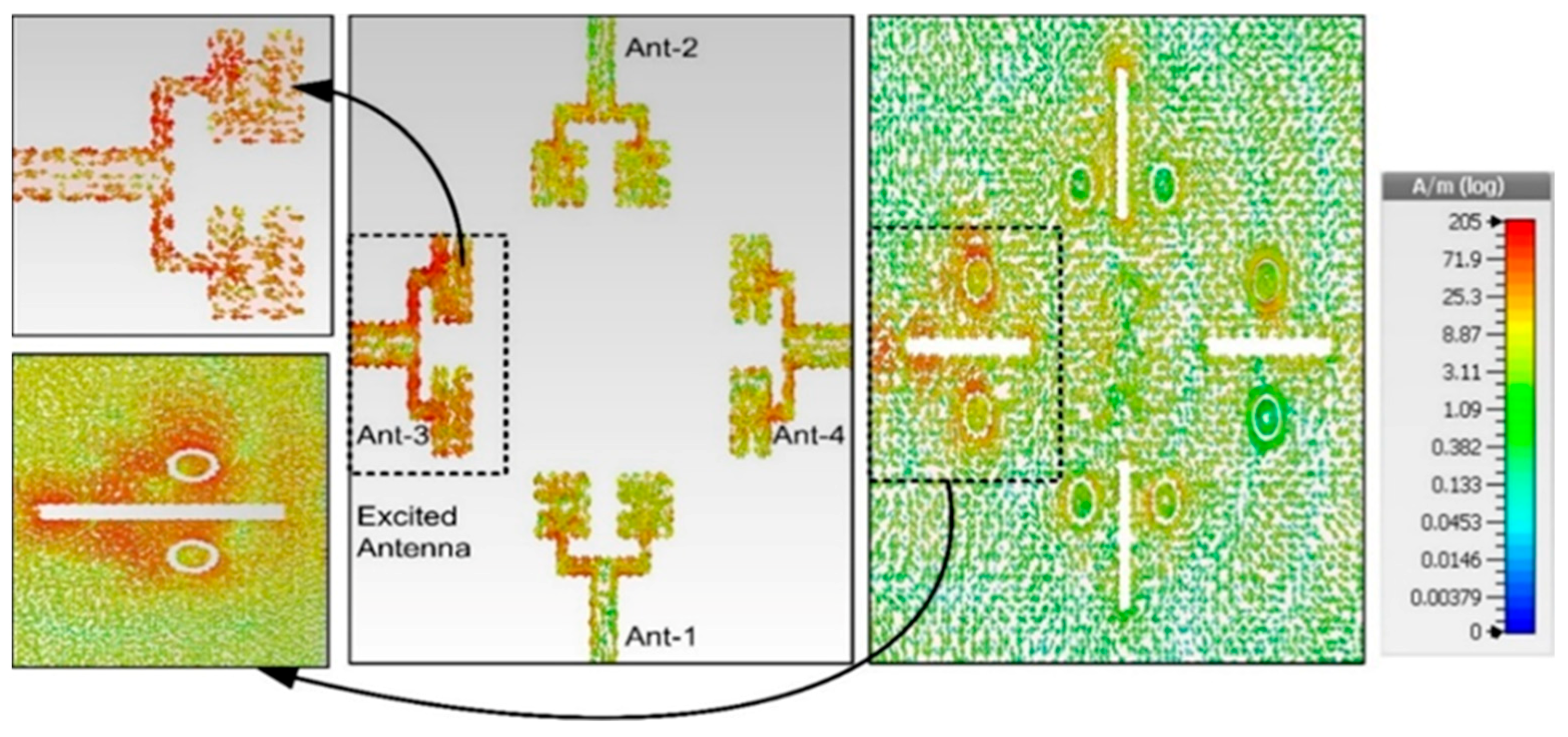
3.2. Surface Current Distribution

The radiating mechanism of the reported MIMO antenna system was analyzed further by investigating the surface current density. This focused on investigating the antenna parts that are influencing the radiation characteristics and elucidating the amount of coupling between different MIMO antennas. Figure 5 shows the surface current distribution when port 3 is activated at 28 GHz. The current flow is mainly concentrated around the feedline and along the edges of the inverted C-shaped antenna. Moreover, the circular and rectangular slots in the ground exhibit significant current distribution. This determines the contribution of DGS in radiation behavior. In addition, the concentration of the coupling current between MIMO antennas is insignificant due to the DGS, as demonstrated in Figure 5.

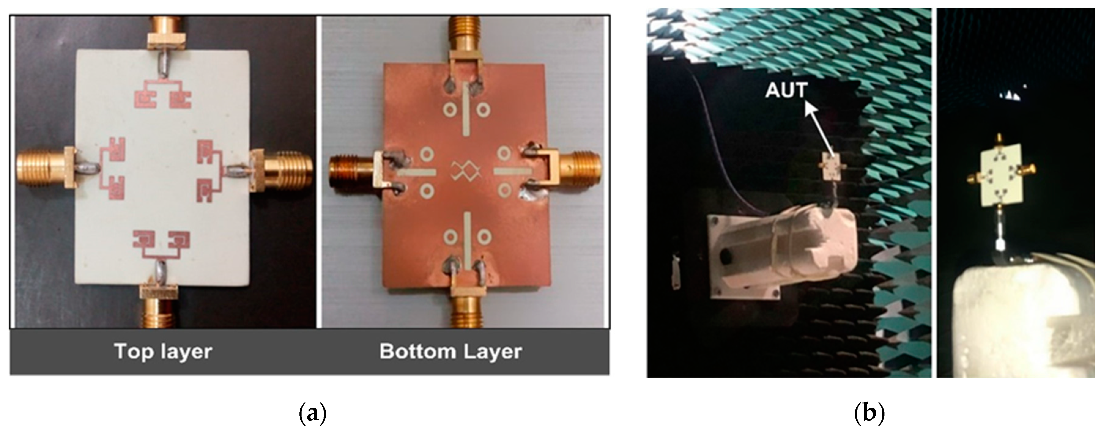
4. Experimental Results

The reported MIMO antenna system was fabricated on a Rogers RO4350B substrate using the photolithography process, and measurements were performed in order to endorse the antenna capabilities for practical utilization. The fabricated prototype and AUT i.e., antenna under test in the anechoic chamber, is shown in Figure 6. The detailed discussion and comparative analysis of measured results are provided in the subsequent section.

4.1. Scattering Parameters

The Scattering parameters of the proposed prototype are measured using the Rohde & Schwarz ZVA 40 VNA. Figure 7a,b illustrate the simulated and measured scattering parameter curves for the reported MIMO antenna. It is observed from the reflection coefficient curve in Figure 7a that MIMO Ant1 is covering the 25.5–29.6 GHz, frequency band. Likewise, the other MIMO antennas exhibit nearly similar reflection coefficient curves with slight shift in bands. The maximum measured bandwidth thus achieved for the proposed antenna is 4.1 GHz. The transmission coefficient analysis is shown in Figure 7b. The minimum measured isolation obtained is −17 dB between the Ant3 and Ant4.
Simulated and measured results are exhibiting good coherence. However, insignificant differences are due to fabrication losses or unavoidable use of coaxial cables during the measurement [36,37]. Hence, the obtained measured results possess the suitability of the reported MIMO antenna for future mm-wave 5G applications.

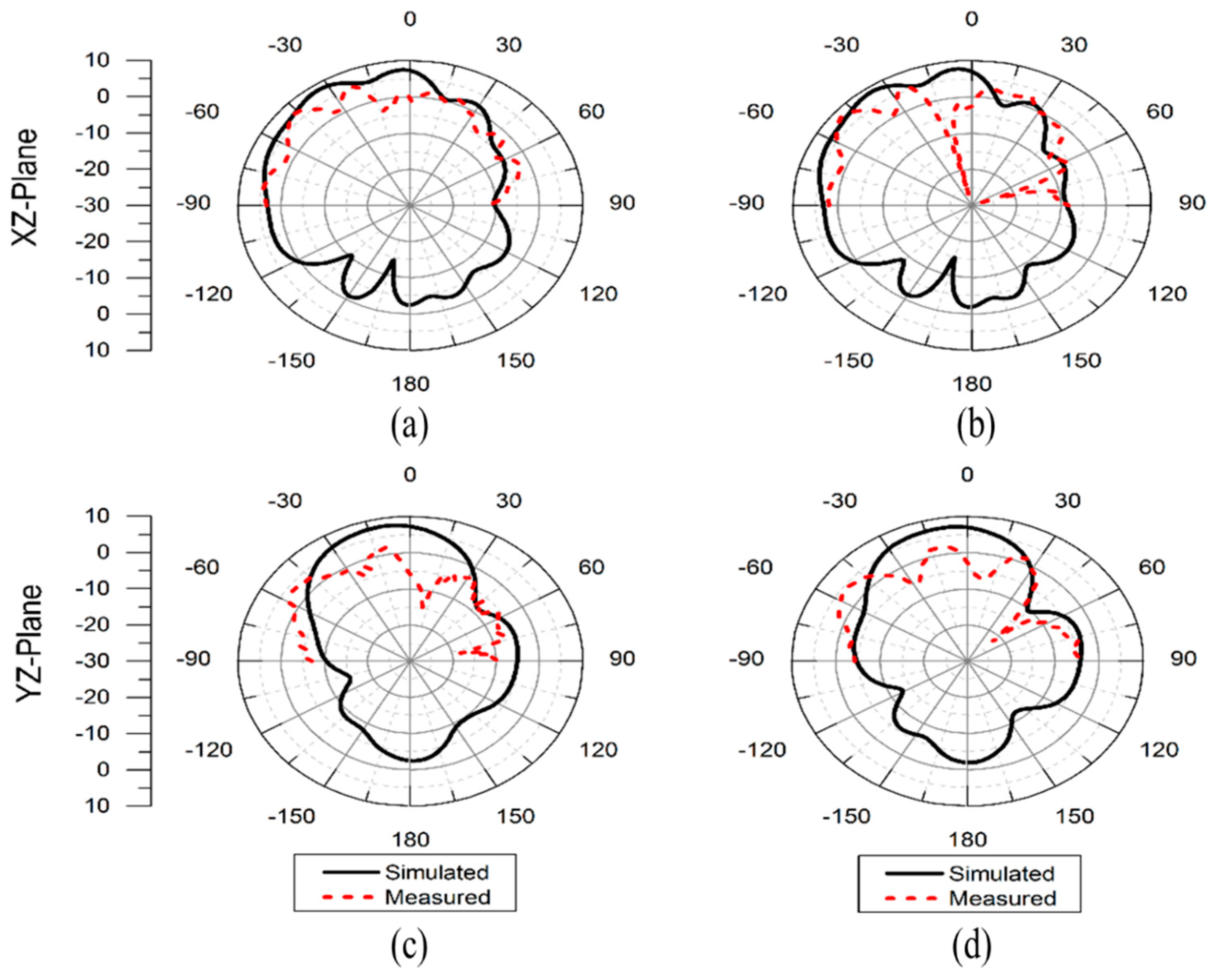
4.2. Radiation Patterns

To understand the radiational behavior of the proposed design, the 2D radiation patterns of antennas were measured using the commercial ORBIT/FR far-field measurement system in an anechoic chamber, as shown in Figure 6b. The far-field measurements were performed in the xz and yz planes with theta range of −90° to 90°. The horn antenna with standard gain of 24 dBi was used for signal transmission. In Figure 8 the simulated and measured 2-D radiation patterns are shown at 27.5 and 28 GHz for Ant1. In the xz plane, the maximum radiation is observed at −35° while in the yz plane, the main beam is directed at −25°. The antenna exhibits overall good performance for both simulated and measured data. However, inconsistencies are observed between simulated and measured results due to fabrication errors and unavoidable cable losses. Also, these sorts of measurement systems are not the most appropriate ones for measuring small antennas, especially in mm wave frequency range, and the effect of the measurement system could affect the results, which in fact creates a discrepancy between simulated and measured results.

4.3. Gain and Percentage Efficiency

The proposed design demonstrates a simulated peak gain value of 8.45 dB while peak measured gain is 8.3 dBi for Ant.1. Similarly, the peak antenna efficiency is about 82% as shown in Table 2. Moreover, the antenna exhibited a nearly stable gain with 3dB gain bandwidth from 26–29.97 GHz.

5. MIMO Performance Parameters

To ensure the proposed antenna’s multi-channel performance was high, the key performance metrics such as ECC, DG, CCL, and MEG were analyzed. Detailed discussion of the parameters is provided below.

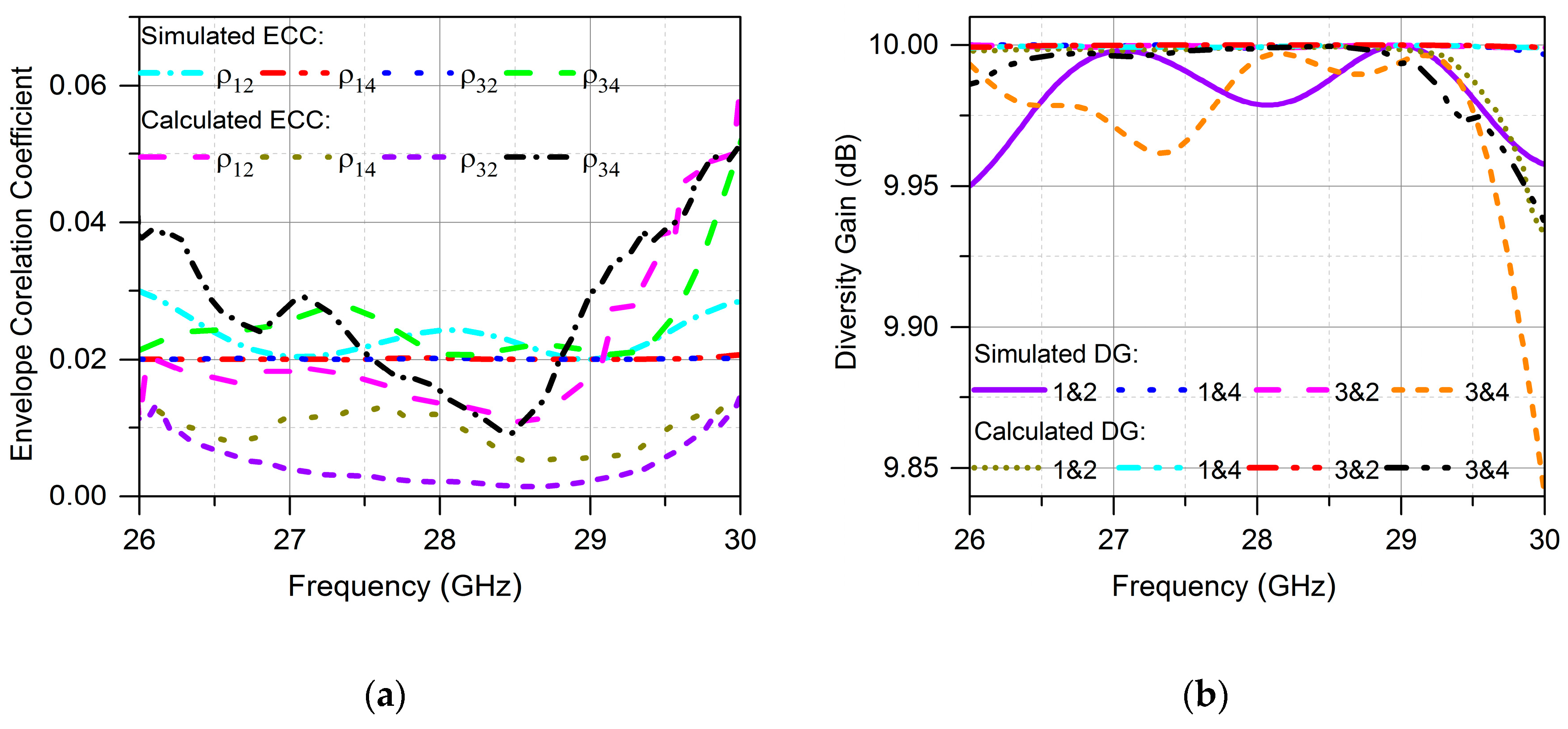
5.1. Envelope Correlation Coefficient (ECC)

ECC is one of the key performance parameters of MIMO systems, and it is calculated using Equation (5) [10]. Figure 9a shows the ECC curve of the proposed antenna over frequency, relatively larger values of ECC are shown between antennas 1 and 2 as well as 3 and 4. The overall antenna module ensures that there are correlation values below the practical standard of 0.5.
ρ eij = | S ii * S ij + S ji * S jj | 2 ( 1 | S ii | 2   S ij   2 ) ( 1 | S ji | 2   S jj   2 )

5.2. Diversity Gain (DG)

Diversity gain demonstrates “the loss in transmission power when diversity schemes are performed on the module” for the MIMO configuration. The diversity gain is calculated by using Equation (6) given in reference [10]. Figure 9b describes the DG to be approximately 10 dB throughout the band, which ensures good diversity performance of the antenna.
DG = 10 1 | ρ eij | 2

5.3. Channel Capacity Loss (CLL)

CCL was enlisted among the MIMO performance parameters, thereby providing details of channels capacity losses of the system during the correlation effect. The CCL is calculated numerically by Equations (7)–(10). Figure 10 illustrates that for the proposed MIMO antenna, the obtained CCL is less than the practical standard of 0.4 bit/s/Hz [38] for the entire operating band, which ensures the proposed system’s high throughput
C ( l o s s ) = l o g 2 det ( a )
where a is the correlation matrix,
a = [ σ 11 σ 12 σ 21   σ 22 ]
σ i i =   1 ( | S i i | 2 | S i j | 2 )
σ i j =   ( S i i * S i j +   S j i S j j   * )

5.4. Mean Effective Gain(MEG)

For diversity, performance analysis mean effective gain is an important parameter and is defined as the mean received power in the fading environment. The mean effective gain is calculated using Equation (11) provided below, and the numerically estimated values are tabulated in Table 3.
M E G i = 0.5   μ i r a d = 0.5   ( 1 j = 1 K | S i j |   )
In this equation, K is the number of antennas, i represents antenna under observation, and μirad is the radiation efficiency. For good diversity performance, the practical standard followed is that MEG should be −3 ≤ MEG (dB) < −12, which is therefore validated for the obtained MEG values of all MIMO antennas of the proposed design.

6. Comparison with Related Work

A comparison with related works reported in literature is tabulated in Table 4. The comparative analysis with other works shows that the proposed design demonstrates better performance in terms of compactness, bandwidth and gain. Moreover, MIMO performance analysis is provided in detail for the proposed design, and it is observed that the MIMO antenna proposed in this work exhibits better performance as compared to other reported works. Hence, the suitability of the proposed MIMO antenna 5G mm–wave applications was ascertained.

7. Conclusions

We presented a four-port MIMO antenna for 5G mm-wave applications. Each MIMO antenna of the proposed design is composed of the wideband and a high gain antenna array of two elements. The operating frequency band is covering 25.5–29.6 GHz, having a bandwidth of 4.1 GHz. Moreover, the measured peak gain obtained for the presented design is 8.3 dBi. Furthermore, to ensure the prototype’s MIMO performance, DG, ECC, CCL, and MEG were also calculated and observed to be within practically acceptable values. The good radiation characteristics of the reported antenna system certify it for the future devices operating in the 5G mm-wave bands.

Author Contributions

Conceptualization M.K. and S.I.N.; Data curation, M.K, S.I.N. and F.; Formal analysis, M.K., S.I.N., and N.H.; Investigation, M.R., M.J.K. and Y.A.; Methodology M.K. and S.I.N. and M.R.; Project administration, Y.A.; Resources, M.R. and S.S.M. and N.H.; Software, M.J.K; Supervision, S.I.N and Y.A.; Validation, M.K. and S.I.N.; Visualization, N.H. and F. and S.S.M.; Writing–original draft, M.K.; Writing–review & editing, S.I.N., N.H., Y.A. and M.R. All authors have read and agreed to the published version of the manuscript.

Funding

This research is funded by the Higher Education Commission of Pakistan Technology development fund (HEC-TDF-67/2017).

Conflicts of Interest

The authors declare no conflict of interest.

References

  1. Andrews, J.G.; Buzzi, S.; Choi, W.; Hanly, S.V.; Lozano, A.; Soong, A.C.; Zhang, J.C. What Will 5G Be? IEEE J. Sel. Areas Commun. 2014, 32, 1065–1082. [Google Scholar] [CrossRef]
  2. Global Mobile Suppliers Association. The Road to 5G: Drivers, Applications, Requirements and Technical Development. Available online: https://www.google.com.hk/url?sa=t&rct=j&q=&esrc=s&source=web&cd=1&cad=rja&uact=8&ved=2ahUKEwimhtnryMPmAhXiGEKHQqMBOcQFjAAegQIAhAC&url=https%3A%2F%2Fwww.huawei.com%2Fminisite%2F5g%2Fimg%2FGSA_the_Road_to_5G.pdf&usg=AOvVaw1RWAb8E8EVfk8xLN0weKBv (accessed on 1 November 2015).
  3. Pi, Z.; Khan, F. An introduction to millimeter-wave mobile broadband systems. IEEE Commun. Mag. 2011, 49, 101–107. [Google Scholar] [CrossRef]
  4. Rappaport, T.S.; Sun, S.; Mayzus, R.; Zhao, H.; Azar, Y.; Wang, K.; Wong, G.N.; Schulz, J.K.; Samimi, M.; Gutierrez, F. Millimeter Wave Mobile Communications for 5G Cellular: It Will Work! IEEE Access 2013, 1, 335–349. [Google Scholar] [CrossRef]
  5. Thompson, J.; Ge, X.; Wu, H.C.; Irmer, R.; Jiang, H.; Fettweis, G.; Alamouti, S. 5G wireless communication systems: Prospects and challenges part 2 [Guest Editorial]. IEEE Commun. Mag. 2014, 52, 24–25. [Google Scholar] [CrossRef]
  6. Zhang, J.; Ge, X.; Li, Q.; Guizani, M.; Zhang, Y. 5G Millimeter-Wave Antenna Array: Design and Challenges. IEEE Wirel. Commun. 2017, 24, 106–112. [Google Scholar] [CrossRef]
  7. Shayea, I.; Abd Rahman, T.; Hadri Azmi, M.; Islam, M.R. Real Measurement Study for Rain Rate and Rain Attenuation Conducted Over 26 GHz Microwave 5G Link System in Malaysia. IEEE Access 2018, 6, 19044–19064. [Google Scholar] [CrossRef]
  8. Zhao, Q.; Li, J. Rain Attenuation in Millimeter Wave Ranges. In Proceedings of the 2006 7th International Symposium on Antennas, Propagation & EM Theory, Guilin, China, 26–29 October 2006; pp. 1–4. [Google Scholar] [CrossRef]
  9. Rahman, M.; NagshvarianJahromi, M.; Mirjavadi, S.S.; Hamouda, A.M. Compact UWB Band-Notched Antenna with Integrated Bluetooth for Personal Wireless Communication and UWB Applications. Electronics 2019, 8, 158. [Google Scholar] [CrossRef] [Green Version]
  10. Sharawi, M.S. Printed Multi-Band MIMO Antenna Systems and Their Performance Metrics [Wireless Corner]. IEEE Antennas Propag. Mag. 2013, 55, 218–232. [Google Scholar] [CrossRef]
  11. Ojaroudi Parchin, N.; Jahanbakhsh Basherlou, H.; Alibakhshikenari, M.; Ojaroudi Parchin, Y.; Al-Yasir, Y.I.A.; Abd-Alhameed, R.A.; Limiti, E. Mobile-Phone Antenna Array with Diamond-Ring Slot Elements for 5G Massive MIMO Systems. Electronics 2019, 8, 521. [Google Scholar] [CrossRef] [Green Version]
  12. Yashchyshyn, Y.; Derzakowski, K.; Bogdan, G.; Godziszewski, K.; Nyzovets, D.; Kim, C.H.; Park, B. 28 GHz Switched-Beam Antenna Based on S-PIN Diodes for 5G Mobile Communications. IEEE Antennas Wirel. Propag. Lett. 2018, 17, 225. [Google Scholar] [CrossRef]
  13. Tang, M.; Shi, T.; Ziolkowski, R.W. A Study of 28 GHz, Planar, Multilayered, Electrically Small, Broadside Radiating, Huygens Source Antennas. IEEE Trans. Antennas Propag. 2017, 65, 6345–6354. [Google Scholar] [CrossRef] [Green Version]
  14. Lin, X.; Seet, B.; Joseph, F.; Li, E. Flexible Fractal Electromagnetic Bandgap for Millimeter-Wave Wearable Antennas. IEEE Antennas Wirel. Propag. Lett. 2018, 17, 1281–1285. [Google Scholar] [CrossRef]
  15. Yoon, N.; Seo, C. A 28-GHz Wideband 2 × 2 U-Slot Patch Array Antenna. J. Electromagn. Eng. Sci. 2017, 17, 133–137. [Google Scholar] [CrossRef] [Green Version]
  16. Ta, S.X.; Choo, H.; Park, I. Broadband Printed-Dipole Antenna and Its Arrays for 5G Applications. IEEE Antennas Wirel. Propag. Lett. 2017, 16, 2183–2186. [Google Scholar] [CrossRef]
  17. Kim, J.; Song, S.C.; Shin, H.; Park, Y.B. Radiation from a Millimeter-Wave Rectangular Waveguide Slot Array Antenna Enclosed by a Von Karman Radome. J. Electromagn. Eng. Sci. 2018, 18, 154–159. [Google Scholar] [CrossRef] [Green Version]
  18. Dzagbletey, P.A.; Jung, Y. Stacked Microstrip Linear Array for Millimeter-Wave 5G Baseband Communication. IEEE Antennas Wirel. Propag. Lett. 2018, 17, 780–783. [Google Scholar] [CrossRef]
  19. Khalily, M.; Tafazolli, R.; Xiao, P.; Kishk, A.A. Broadband mm-Wave Microstrip Array Antenna with Improved Radiation Characteristics for Different 5G Applications. IEEE Trans. Antennas Propag. 2018, 66, 4641–4647. [Google Scholar] [CrossRef]
  20. Zhu, S.; Liu, H.; Chen, Z.; Wen, P. A Compact Gain-Enhanced Vivaldi Antenna Array with Suppressed Mutual Coupling for 5G mmWave Application. IEEE Antennas Wirel. Propag. Lett. 2018, 17, 776–779. [Google Scholar] [CrossRef]
  21. Briqech, Z.; Sebak, A.; Denidni, T.A. Low-Cost Wideband mm-Wave Phased Array Using the Piezoelectric Transducer for 5G Applications. IEEE Trans. Antennas Propag. 2017, 65, 6403–6412. [Google Scholar] [CrossRef]
  22. Yu, B.; Yang, K.; Sim, C.; Yang, G. A Novel 28 GHz Beam Steering Array for 5G Mobile Device with Metallic Casing Application. IEEE Trans. Antennas Propag. 2018, 66, 462–466. [Google Scholar] [CrossRef]
  23. Bang, J.; Choi, J. A SAR Reduced mm-Wave Beam-Steerable Array Antenna with Dual-Mode Operation for Fully Metal-Covered 5G Cellular Handsets. IEEE Antennas Wirel. Propag. Lett. 2018, 17, 1118–1122. [Google Scholar] [CrossRef]
  24. Ikram, M.; Wang, Y.; Sharawi, M.S.; Abbosh, A. A novel connected PIFA array with MIMO configuration for 5G mobile applications. In Proceedings of the 2018 Australian Microwave Symposium (AMS), Brisbane, Australia, 6–7 February 2018; pp. 19–20. [Google Scholar] [CrossRef]
  25. Iqbal, A.; Basir, A.; Smida, A.; Mallat, N.K.; Elfergani, I.; Rodriguez, J.; Kim, S. Electromagnetic Bandgap Backed Millimeter-Wave MIMO Antenna for Wearable Applications. IEEE Access 2019, 7, 111135–111144. [Google Scholar] [CrossRef]
  26. Park, J.; Ko, J.; Kwon, H.; Kang, B.; Park, B.; Kim, D. A Tilted Combined Beam Antenna for 5G Communications Using a 28-GHz Band. IEEE Antennas Wirel. Propag. Lett. 2016, 15, 1685–1688. [Google Scholar] [CrossRef]
  27. Sun, Y.; Leung, K.W. Substrate-Integrated Two-Port Dual-Frequency Antenna. IEEE Trans. Antennas Propag. 2016, 64, 3692–3697. [Google Scholar] [CrossRef]
  28. Sharawi, M.S.; Podilchak, S.K.; Hussain, M.T.; Antar, Y.M.M. Dielectric resonator based MIMO antenna system enabling millimetre-wave mobile devices. IET Microw. Antennas Propag. 2017, 11, 287–293. [Google Scholar] [CrossRef] [Green Version]
  29. Yang, B.; Yu, Z.; Dong, Y.; Zhou, J.; Hong, W. Compact Tapered Slot Antenna Array for 5G Millimeter-Wave Massive MIMO Systems. IEEE Trans. Antennas Propag. 2017, 65, 6721–6727. [Google Scholar] [CrossRef]
  30. Jilani, S.F.; Alomainy, A. Millimetre-wave T-shaped MIMO antenna with defected ground structures for 5G cellular networks. IET Microw. Antennas Propag. 2018, 12, 672–677. [Google Scholar] [CrossRef]
  31. Shoaib, N.; Shoaib, S.; Khattak, R.Y.; Shoaib, I.; Chen, X.; Perwaiz, A. MIMO Antennas for Smart 5G Devices. IEEE Access 2018, 6, 77014–77021. [Google Scholar] [CrossRef]
  32. Saad, A.A.R.; Mohamed, H.A. Printed millimeter-wave MIMO-based slot antenna arrays for 5G networks. AEU Int. J. Electron. Commun. 2019, 99, 59–69. [Google Scholar] [CrossRef]
  33. Jiang, H.; Si, L.; Hu, W.; Lv, X. A Symmetrical Dual-Beam Bowtie Antenna with Gain Enhancement Using Metamaterial for 5G MIMO Applications. IEEE Photonics J. 2019, 11, 1–9. [Google Scholar] [CrossRef]
  34. Hussain, N.; Jeong, M.; Park, J.; Kim, N. A Broadband Circularly Polarized Fabry-Perot Resonant Antenna Using A Single-Layered PRS for 5G MIMO Applications. IEEE Access 2019, 7, 42897–42907. [Google Scholar] [CrossRef]
  35. Zhang, Y.; Deng, J.; Li, M.; Sun, D.; Guo, L. A MIMO Dielectric Resonator Antenna with Improved Isolation for 5G mm-Wave Applications. IEEE Antennas Wirel. Propag. Lett. 2019, 18, 747–751. [Google Scholar] [CrossRef]
  36. Liu, L.; Cheung, S.W.; Weng, Y.F.; Yuk, T.I. Cable Effects on Measuring Small Planar UWB Monopole Antennas, in Ultra Wideband Current Status and Future Trends; InTech: London, UK, 2012; Chapter 12. [Google Scholar]
  37. Liu, L.; Weng, Y.F.; Cheung, S.W.; Yuk, T.I.; Foged, L.J. Modeling of cable for measurements of small monopole antennas. In Proceedings of the Loughborough Antennas Propagation Conference (LAPC), Loughborough, UK, 14–15 November 2011; pp. 1–4. [Google Scholar]
  38. Chae, S.H.; Oh, S.; Park, S. Analysis of Mutual Coupling, Correlations, and TARC in WiBro MIMO Array Antenna. IEEE Antennas Wirel. Propag. Lett. 2007, 6, 122–125. [Google Scholar] [CrossRef]
Figure 1. Proposed Multiple-Input-Multiple-Output (MIMO) Antenna module (a) Top view (b) bottom without a Defected Ground Structure (DGS).
Electronics 09 00071 g001
Figure 2. Proposed antenna geometry (a) Single element (b) Top layer of array antenna (c) Bottom layer.
Electronics 09 00071 g002
Figure 3. Simulated Reflection Coefficient of (a) Single Element, Two Element array, MIMO Ant1 (b) Reflection coefficient of MIMO Ant1 and Ant3 with and without DGS.
Electronics 09 00071 g003
Figure 4. Simulated Transmission Coefficient (a) Without DGS (b) With DGS.
Electronics 09 00071 g004
Figure 5. Surface current distribution along with the reported MIMO antenna design.
Electronics 09 00071 g005
Figure 6. (a) Fabricated antenna module (b) antenna module in measurement.
Electronics 09 00071 g006
Figure 7. Measured and Simulated scattering parameter curves (a) Reflection coefficient curves (b) Transmission coefficient curves.
Electronics 09 00071 g007
Figure 8. Measured and simulated 2D radiation pattern of antenna 1 (a) Radiation pattern at XZ-plane at 27.5 GHz (b) Radiation pattern at XZ-plane at 28 GHz (c) Radiation pattern at YZ-plane at 27.5 GHz (d) Radiation pattern at YZ-plane at 28 GHz.
Electronics 09 00071 g008
Figure 9. (a) ECC of the proposed MIMO antenna array (b) Diversity Gain of the MIMO antenna array.
Electronics 09 00071 g009
Figure 10. Channel capacity loss analysis of proposed MIMO antenna.
Electronics 09 00071 g010
Table 1. Optimized Design Parameters.
ParameterValue(mm) ParameterValue(mm)ParameterValue(mm)
Wp3Lp2G0.8
Wf1.66Lf3.4G10.2
W11.6L11.35Wm3.5
Wf10.42Lf11.5r0.6
Wsg1.25Lsg5.2r11.3
W30L35Lz1.9
a0.7b1.5h0.76
Table 2. Measured and simulated gain and efficiency.
Frequencies
(GHz)
Gain at Antenna-1 (dBi)Percentage Efficiency
SimulatedMeasuredSimulatedMeasured
27.58.458.38079
288.18.028280
28.58.228.18582
Table 3. The mean effective gain of the reported antenna.
FrequencyMean Effective Gain (-dB)
(GHz)Ant-1 Ant-4 Ant-3 Ant-4
267.2438927.285627.6232447.208327
26.56.754366.6025457.3592966.676395
276.7986826.4954187.8733147.096469
27.57.0028226.5496477.1353897.211303
286.9610636.6523166.8876857.075835
28.56.8328576.6348967.0203926.901157
296.6620246.5342487.6308517.051805
29.56.5761117.0241268.368037.311751
307.1013938.2038159.0899057.458108
Table 4. Performance comparison with recent state of the art in the literature.
Ref.Frequency
(GHz)
Board Size
(mm3)
No. of PortsBandwidth
(GHz)
Gain
(dBi)
ECC, DG
(dB)
CCL
Bits/s/Hz
[11]3.6150 × 75 × 1.681.22.5<0.01,
Not provided
Not provided
[15]2841.3 × 46 × 0.50843.3513.1Not providedNot provided
[25]2415 × 19 × 0.25420.86 0.24,
9.7
Not provided
[26]28Not provided41.57.41Not providedNot provided
[27]5.2 & 2440 × 25 × 0.25420.1 & 0.775 &7.37Not providedNot provided
[28]3048 × 21 × 0.1321>7<0.4,
Not provided
Not provided
[34]2819 × 19 × 7.6084 (multi-layers)814 dBiC0.05,
Not provided
Not provided
[35]2820 × 20 × 0.25420.858 dB0.13,
9.9
Not provided
This work2830 × 35 × 0.7644.18.3 dB<0.01, >9.96<0.4

