1. Introduction
The first roundabout in history is apparently the Circus in Bath [
1], but modern roundabouts with the priority rule were first made mandatory in the United Kingdom in 1966. Roundabouts of this type have been widely adopted because they provide a significant reduction in the number of accidents with injuries and fatalities when compared with intersections [
2,
3] and old traffic circles where the vehicles entering had the priority. Modern roundabouts provide more safety and lower delay than signaled intersections with traffic lights [
4]. Although different improvements in the design of roundabouts have been adopted, including turbo-roundabouts [
5] and the so-called "magic roundabout" [
6], the basic rule of absolute priority to the vehicles inside the roundabout has been kept because it provides increased safety and prevents blocking in most circumstances (not all). Surprisingly, while roundabouts’ physical design has improved over the decades, their signaling and control have not evolved accordingly. Nowadays, vehicular networks appear to be an important tool to improve safety and capacity of roads [
7,
8]. However, most proposals for more efficient roundabouts and intersections are based on full driving automation and do not apply to human-driven vehicles, making the transition problematic [
9]. The motivation of this paper is as follows: the capacity of roundabouts is currently limited by the drivers (gap acceptance), more specifically the duration of the critical headway (gap) and the follow-up headway [
10]. The critical and follow-up headways’ value is high due to the frequent stops and speed changes at the roundabout entrance caused by the lack of priority of the incoming traffic and the internal conflicts between vehicles willing to leave the roundabout and vehicles continuing their traversal. The basic idea is that eliminating conflicts via uniform speeds and synchronized platoons, safety and capacity will increase significantly. Our approach looks at roundabouts as synchronous, time-division switches or multiplexers of vehicles, although taking into account the non-negligible transmission (displacement) delays inside the roundabout.
This paper describes the synchronous rotating priority sectors (SYROPS) roundabout, a new roundabout traffic signaling and control system compatible with human-driven and autonomous vehicles. Signaling is visual for human-driven vehicles and also wireless for connected and autonomous vehicles. Most current advances in car safety (anti-collision systems, lane control, cruise control and signal reading) are compatible and synergistic with the proposed system (e.g., anticollision systems allow much shorter inter-vehicle safe distances and higher capacity), and new ones can be devised capable of understanding SYROPS signaling. The basic concept is to divide the roundabout circle into sectors and assign each sector exclusive access. These sectors rotate at the same speed as the vehicles in the roundabout. By forming compact platoons of vehicles that arrive at the roundabout at speed equal to the roundabout’s average linear speed and within the time of the passage of the rotating priority sector of their access, conflicts and subsequent stops are avoided, increasing the roundabout’s capacity and safety.
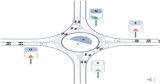
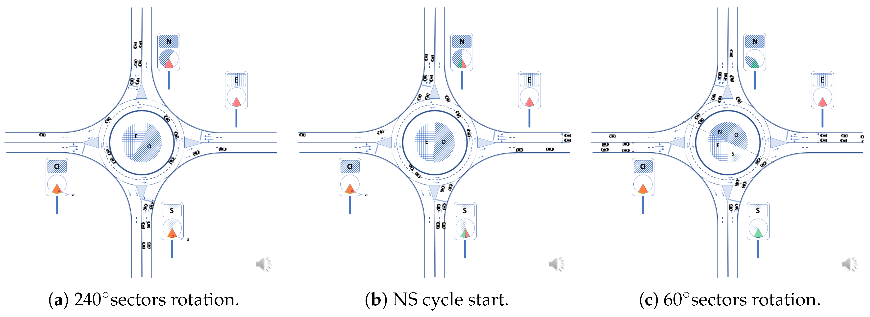
An example of a revolving roundabout with rotating priority sectors is shown in
Figure 1. We evaluate analytically and with SUMO [
11] simulations the capacities of roundabouts with two rotary 180
sectors alternatively assigned to north–south and east–west every 270
rotation. Results obtained for roundabouts of different radii and various assumptions for distances between vehicles are provided and compared with current capacity models published in Highway Capacity Manuals [
10,
12] with excellent delay results, thereby providing higher levels of service.
The paper is structured as follows. The next section outlines related work.
Section 3 provides an overview of the system, while
Section 4 describes in detail an example of signaling and a vehicle access sequence.
Section 5 contains the evaluation and discussion about the applicability and implementation of static and dynamic signaling variants. Finally,
Section 7 is the conclusion.
2. Related Work
The current practice on roundabout design and evaluation is documented in many empirical studies and usually incorporated in the state-of-the-art recommendations from official bodies, such as HCM [
10] in the USA and other countries [
4]. The second edition (2010) of the Roundabouts Informational Guide is a complete guide on the subject [
13].
The use of metering signals and stop lines at the roundabout’s access points to create gaps that improve its performance are proven techniques [
4,
14]. Various roundabout designs are known, including the turbo-roundabouts [
15], which seek to reduce the number of conflict points in roundabouts. Regarding roundabout signaling, the design of [
16] for conventional vehicles at roundabouts uses a central ring at the roundabout with two operating modes: either it lights up in sequence, so that the lights (like arrows) move in the direction of rotation of vehicles at the roundabout, or flashes to indicate caution.
Reza Azimi has studied the control of the flow of autonomous and enhanced vehicles extensively at intersections and roundabouts, based on allocating virtual slots to vehicles [
9,
17,
18]. Although the proposals and analysis are solid, and the performance improves, crossing the intersections and roundabouts may be terrifying for the autonomous vehicles’ passengers. More recent work has evolved Azimi’s work to increase safety and passengers’ psychological comfort [
19].
Various technologies and standards try to optimize traffic flow in roundabouts, intersections and other environments through wireless communications between each vehicle and the environment. They are encompassed in the V2X (vehicle to everything) concept [
20], which includes communication between vehicles; vehicles and road infrastructure; and vehicles and pedestrians. Mobile technologies such as 3GPP and vehicular communication at ITS of ETSI [
21] use wireless communication.
These autonomous vehicle coordination technologies (automatic driving) are not applicable when driving conventional vehicles with drivers, so it is necessary to improve the performance and safety of roundabouts through procedures applicable to both driver and autonomous vehicles. The problem of roundabout crossing using virtual platoons of autonomous and manually-driven vehicles was studied in [
22]. The term virtual platoon applies to vehicles that may circulate at different roundabout lanes and coordinate their arrival to the roundabout for safe crossing. An analysis of hybrid driven human and CAV vehicles at a microscopic level is given in [
19].
3. Methods
We propose the basis of a new system for signaling and control of roundabouts for both connected vehicles and manually-driven vehicles. Any roundabout capacity is, roughly speaking, directly proportional to the average vehicle speed and inversely to the average inter-vehicle distance. If we increase the first and reduce the second, capacity increases. Roundabouts are currently limited in capacity and safety by conflict points. Roundabouts have multiple points of conflict between vehicles, more precisely, 24 conflict points for a double lane roundabout and 14 for a turbo-roundabout, as shown in
Figure 2.
The conflict points often provoke stops at the roundabout entrances, reduce average speed and increase the inter-vehicle gap (critical headway) needed by a vehicle to safely enter the roundabout. The stops also increase vehicle distances (follow-up headway) and lower the capacity of the roundabout. Our proposal’s basis is that by making the traffic regular and smooth at accesses, with constant speeds and controlled delays, and by isolating the traffic from every access at a separate rotating sector, the conflict points at the entries and inside the roundabout will be eliminated; the subsequent stops and deceleration will be less prevalence; and capacity and safety will increase. The vehicle’s priority inside the roundabout is no longer permanent, and it is dynamically assigned to rotating sectors of variable duration, each one associated with a different entry.
3.1. Working Principle
The vehicles from each roundabout access are grouped into platoons to maximize the lane’s occupancy and avoid stops in the roundabout, such that the arrival times of the platoons of the two perpendicular directions are staggered to avoid access conflicts. The capacity is optimized by the just-in-time, centrally controlled platoon’s arrival to the roundabout, while the synchronization of arrivals is based on the staggering of orthogonal platoons and platoon formation and control. Maximum smoothness is obtained by equating the vehicle circulation speed at accesses with the roundabout’s linear speed. The system uses vertical visual signaling in the form of circular light sectors (and optionally collocated traffic lights that confirm the information) to indicate the status of access priorities. The platoons of vehicles are formed and compacted using moving illuminated signs in front of the platoon head and the platoons located on the entrances’ sides, and transversely on the entrance floor or by other procedures, including wireless signaling for connected/autonomous vehicles. These platoon head signs (e.g., north and south accesses) approach the roundabout at a constant speed, synchronizing the entrance to the roundabout of the platoons of vehicles for each two accesses from opposite directions. The perpendicular direction signs (e.g., east and west accesses) have a spatial and temporal offset adjusted to match vehicles’ arrival from the pair of accesses to the roundabout with the start of their access priority, avoiding most stops at the roundabout entrance. Besides, stop lines’ placement at a certain distance before the roundabout allows the vehicles to enter the roundabout at the same speed as the rotating priority sector.
3.2. System Description and Operation
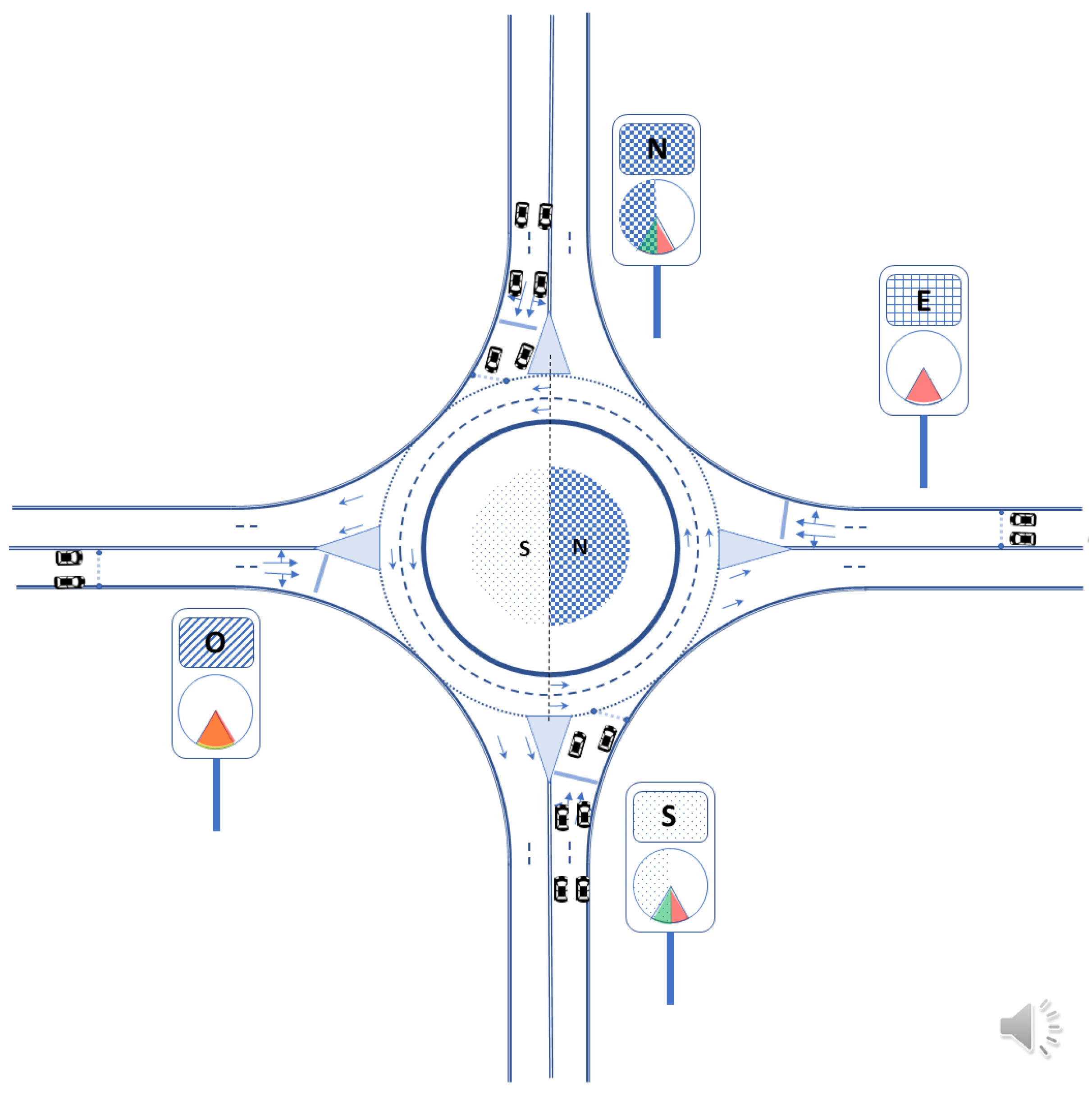
Figure 3 shows a roundabout equipped with vertical light signaling devices (12, 13, 16, 17 and 18) located at the entrances to the roundabout and on the central island (10).
Around the central island (10), a ring (11) is formed by a set of programmable color lights showing colored circular sectors. The ring rotates at a speed similar to the average speed of vehicles in the roundabout. The vertical panels serve to show, in an analog form, the positions of the sectors of the central light ring to the vehicles of each access. The panels contain a circle (14) in which the same colored circular sectors (15) are shown, replicating the positions of the sectors of the ring vertically, as seen from the vehicles that reach the roundabout through each access, as it would be if the ring (11) were placed vertically perpendicular to each of the accesses.
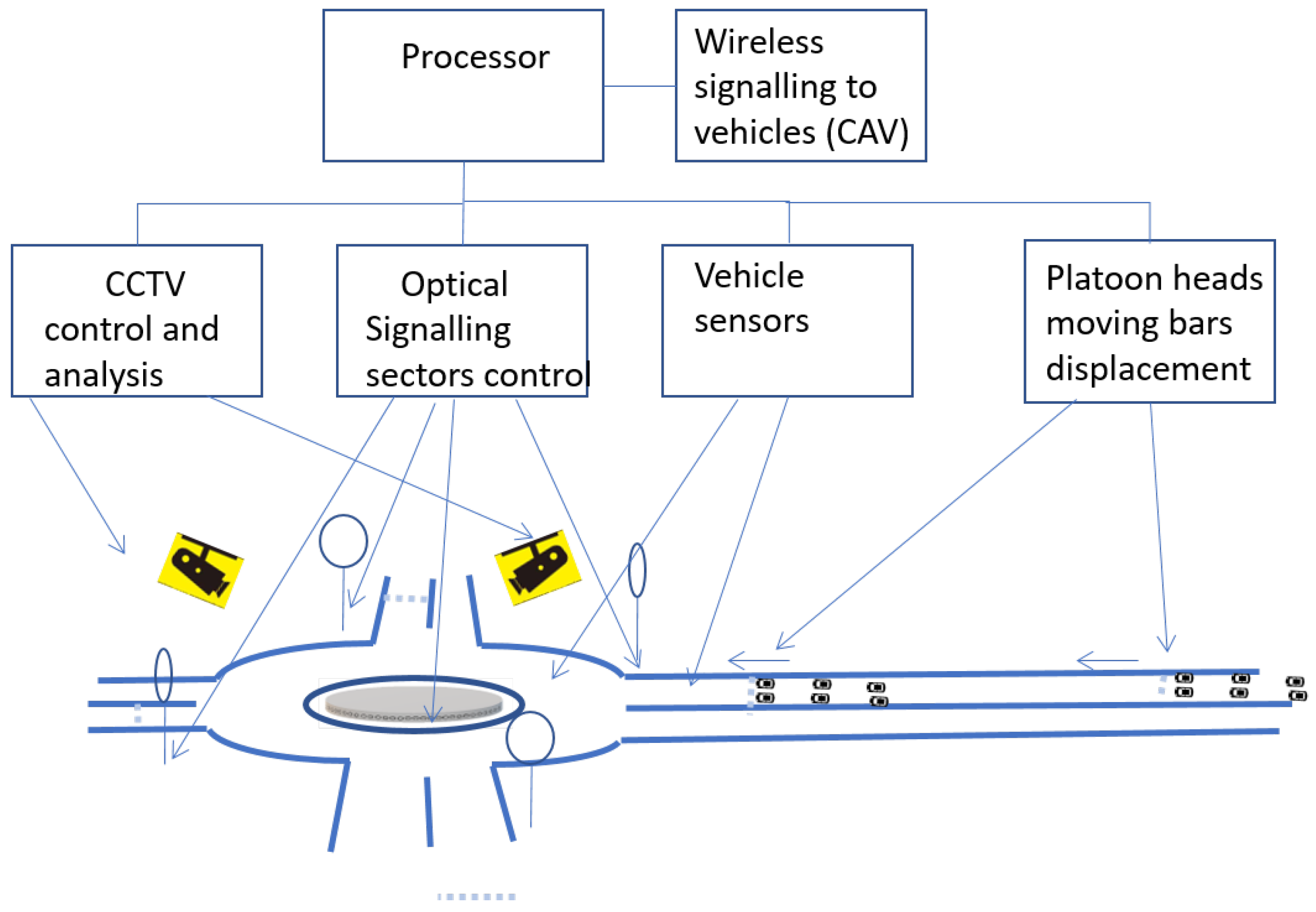
Figure 4 shows a block diagram of the system, comprising a processing unit that communicates with the camcorder control, wireless communication with connected vehicles, TV cameras, image interpretation software, vertical light panels and vehicle sensors. The mobile light signals that mark the starts of platoons at the accesses are also controlled by the processing unit and indicate at all times the forward limit of the vehicle platoon not to be exceeded to maintain the synchronicity of the platoon arrival with its assigned priority sector.
The processing unit obtains the characteristics of the traffic from the sensors and camcorders: intensity, average speed and degree of grouping, and depending on these, it modifies or not the movement speed of each approach light signal, the absolute and relative duration of the sectors and the speed of rotation of the sectors in the panels and the central light ring. The maximum width of the sectors is, by default, 180 degrees, and the processing unit extends or decreases its duration depending on the traffic detected by the sensors and camcorders and the programmed traffic policies. When the sensors or cameras detect the start of the formation of a queue in some access, the corresponding access sector’s size is increased to facilitate eliminating the queue, preventing the stops of the platoons at the accesses with more traffic. The far platoons of competing accesses (perpendicular) can be slowed down slightly to compensate for this increase, or the platoon size is reduced by the sector’s duration reduction. As indicated in the vertical and horizontal signals, vehicles turning 90 degrees to the right must access the roundabout in the right lane. Vehicles going straight (second exit, 180 degrees) may use the right or left lane of access. Vehicles that will turn 270 degrees (turn left) must necessarily take the left lane of access.
In this implementation variant, the 360-degree turn (change of direction) in the roundabout is not considered, but it is feasible by increasing the distances between platoons of vehicles. A vehicle that remains in the roundabout after its 270 degrees of rotation loses its priority and must yield to vehicles accessing the roundabout. The same would happen at 360 degrees if the 360-degree turn were allowed. The restriction of the entrance lane to be used by vehicles depending on their exit, together with the zoning of the priorities in the roundabout, avoids conflicts between vehicles to exit the roundabout. These conflicts are quite common in standard roundabouts (as shown in
Figure 2) when, while passing an access, the vehicle on the outer lane of the roundabout wishes to continue in the roundabout, and the vehicle on the inner lane wishes to exit through the nearby access, crossing the paths of both vehicles and forcing the deceleration of one of them. The vertical light panels at each entry show the same information as the central light ring in the way that is most relevant for vehicle drivers: the color and pattern univocally associated with that entry; the turning position of the sector that gives priority to the entry, showing the total size of this sector when it is fully deployed; and a fixed circular sector of about 60 degrees (the lower sector of the vertical circle), which visualizes the status of the priority of that access through the conventional colors of green, flashing yellow and red. When the light sector of that access enters this lower 60
sector, the shared surface (i.e., the geometrical intersection) for both sectors is shown in green (g), to provide an analog visualization of its priority sector position and priority time remaining.
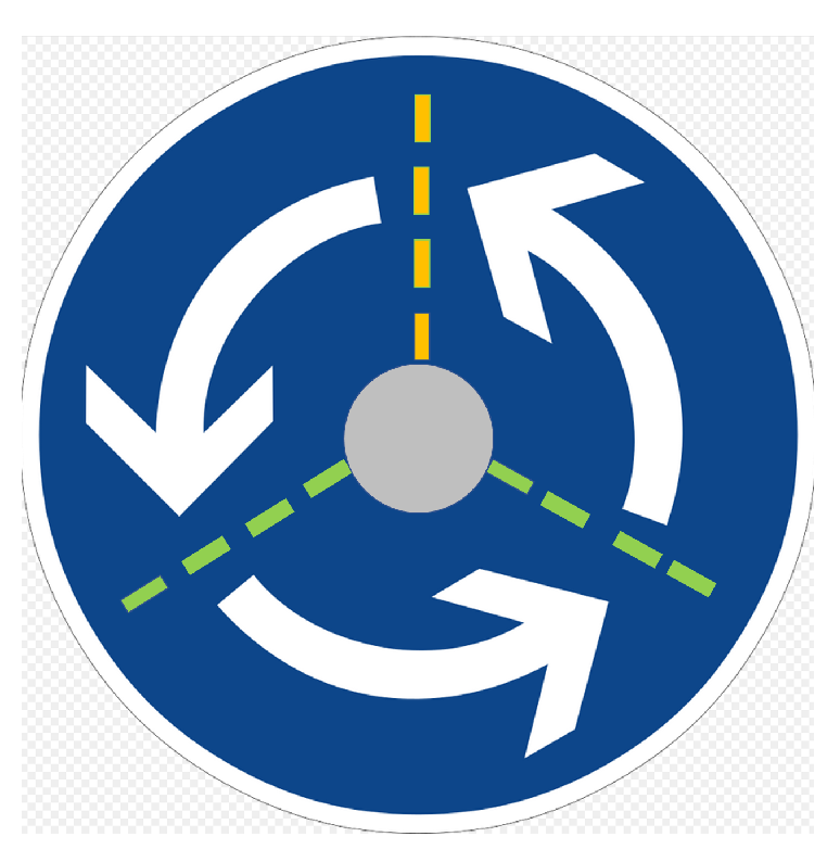
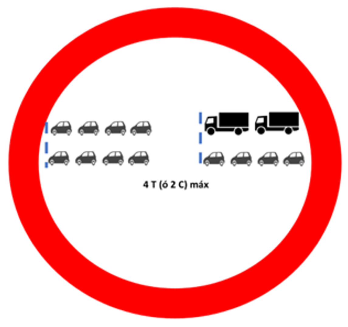
Figure 5 shows a suggested traffic signal (EU style) to inform one about the proximity of a rotating-priorities roundabout, while
Figure 4 shows the illuminated platoon head mobile signs (32), located on the sides of the accesses and the ground. The ground signs light up sequentially in the direction of travel at the recommended speed of access, indicating the front line of the vehicle platoon.
To form the platoons of vehicles of the appropriate size (e.g., from two rows of four vehicles), the dynamic platoon header lines are initially at the beginning of the platoon circulation area delimited by the signals (
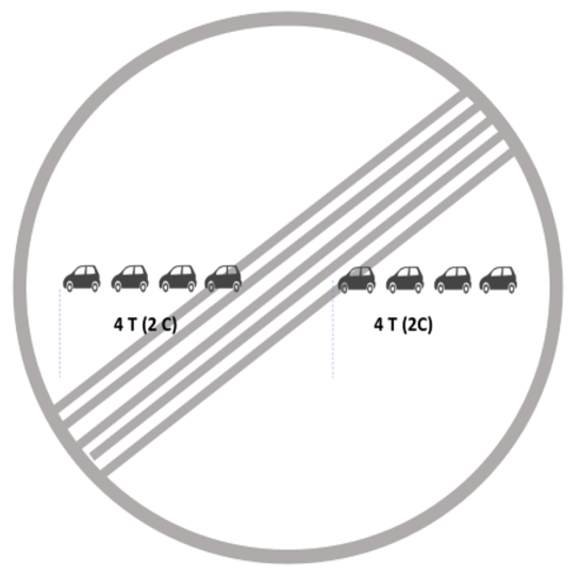
Figure 6 and
Figure 7), and controlled by the central processing unit. This distance between platoon heads is, for the variant described, a distance equivalent to 1.5 times the length of the roundabout’s central circumference (the line separating the two lanes). The maximum number of consecutive vehicles per row of the platoon depends on the dimensions of the roundabout. Drivers are informed in the sign of
Figure 6 of the maximum platoon length in the number of consecutive cars (C) and trucks (T), and the minimum but recommended distance to keep from the preceding platoon. The stop lines at the accesses, only used in case of congestion, are located at a distance from the roundabout that is sufficient to reach the speed of the rotating sectors to maintain the smoothness of operation.
3.3. Platooning
The two key aspects of SYROPS roundabouts are the platooning of vehicles at each entry and their adequate orthogonal staggering to arrive just-in-time to the roundabout access when the access gets the rotating priority. The platoons must first be formed and then maintained while circulating at the mandatory speed to achieve it.
Other complementary or alternative methods to form the platoons are the following:
Horizontal signals on the roads (also known as “chevrons”). The platoon heads should keep at least two chevrons distance with the preceding platoon.
Moving horizontal traversal lights and/or lateral lights at both sides of the access that indicate the start of the platoon head. These light move at the same linear speed as the middle radius of the roundabout.
Wireless signaling infrastructure for connected autonomous vehicles.
Optical and acoustic signals to drivers from a smartphone application.
Vehicles with semi-autonomous capabilities (like collision avoidance systems) might be enabled for automatic platoon following.
3.4. Exception Handling
Handling of exceptions at the roundabout (like a vehicle staying at the roundabout after his priority has elapsed or a stopped vehicle), must be designed ad hoc based on simulations and real environment experiments. The general principles are based on safety and traffic fluidity and go in the direction of switching back to conventional roundabout operation, with all lights in flashing yellow and priority to the vehicles inside the roundabout. If the exception can be handled by the system just by delaying some sectors’ priorities or extending existing ones, it is done in this way. In the evaluation section, the “U-turn allowed” paragraph describes an example of 90 void sector usage during the transition from N–S to E–W sectors, to increase the time available for the vehicles to empty the roundabout.
3.5. Technology Usage
Multiple technologies are used in the proposed system. TV cameras and vehicle presence and speed sensors allow the system to understand the roundabout situation and abnormal situations, and optimize the regular operation’s access signaling duration. Lit speed indicators inform the incoming vehicles of their speed may help keep the speed constant at vehicle platoons and compact the platoons. Mobile navigation applications may also provide audible signals to the driver to increase or decrease his/her speed. Vehicle to vehicle (V2V) communications could be used in two ways: a complement for better vehicle platooning or as the central technology for a possible fully distributed SYROPS implementation.
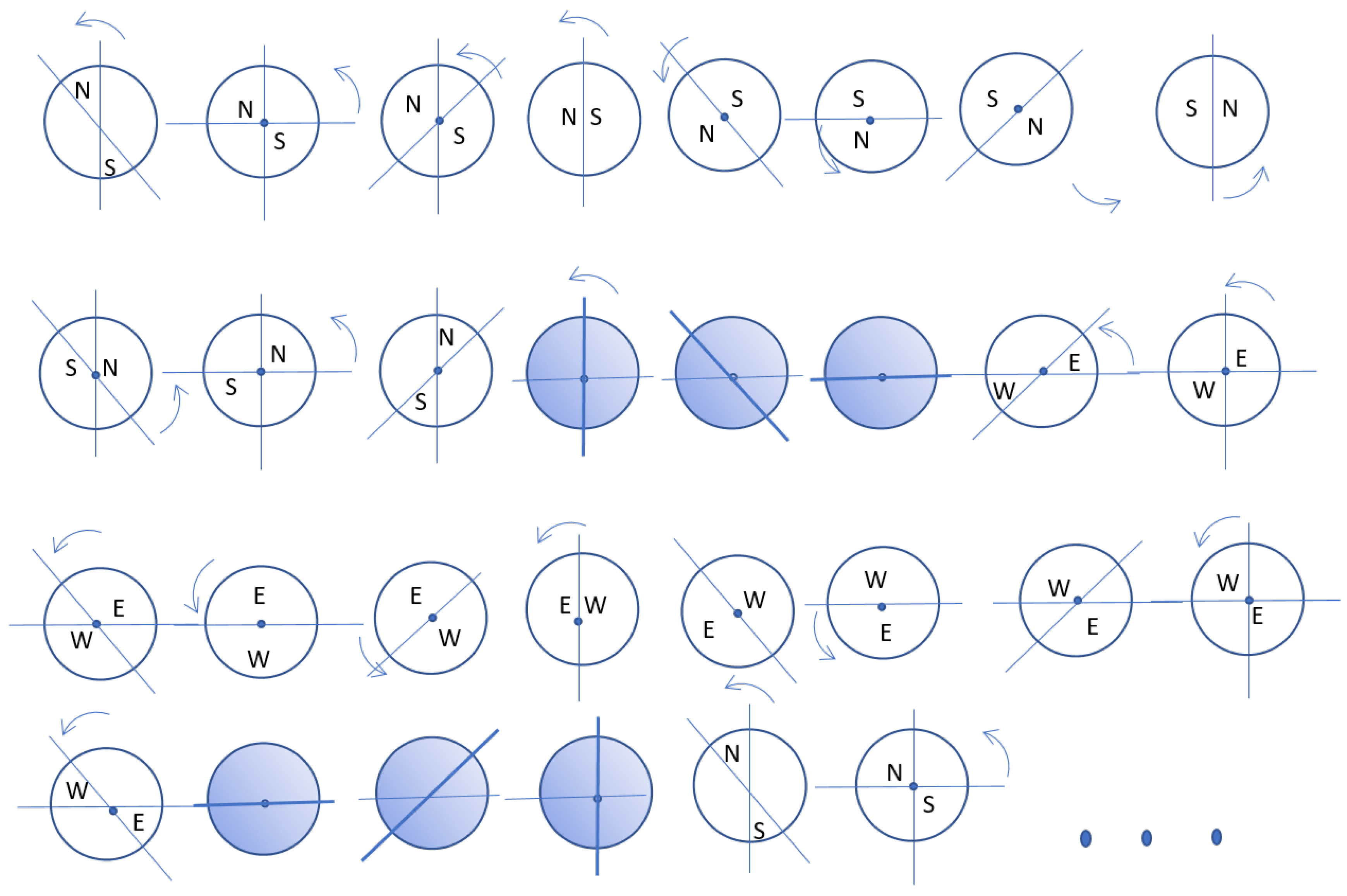
4. Sequence Example
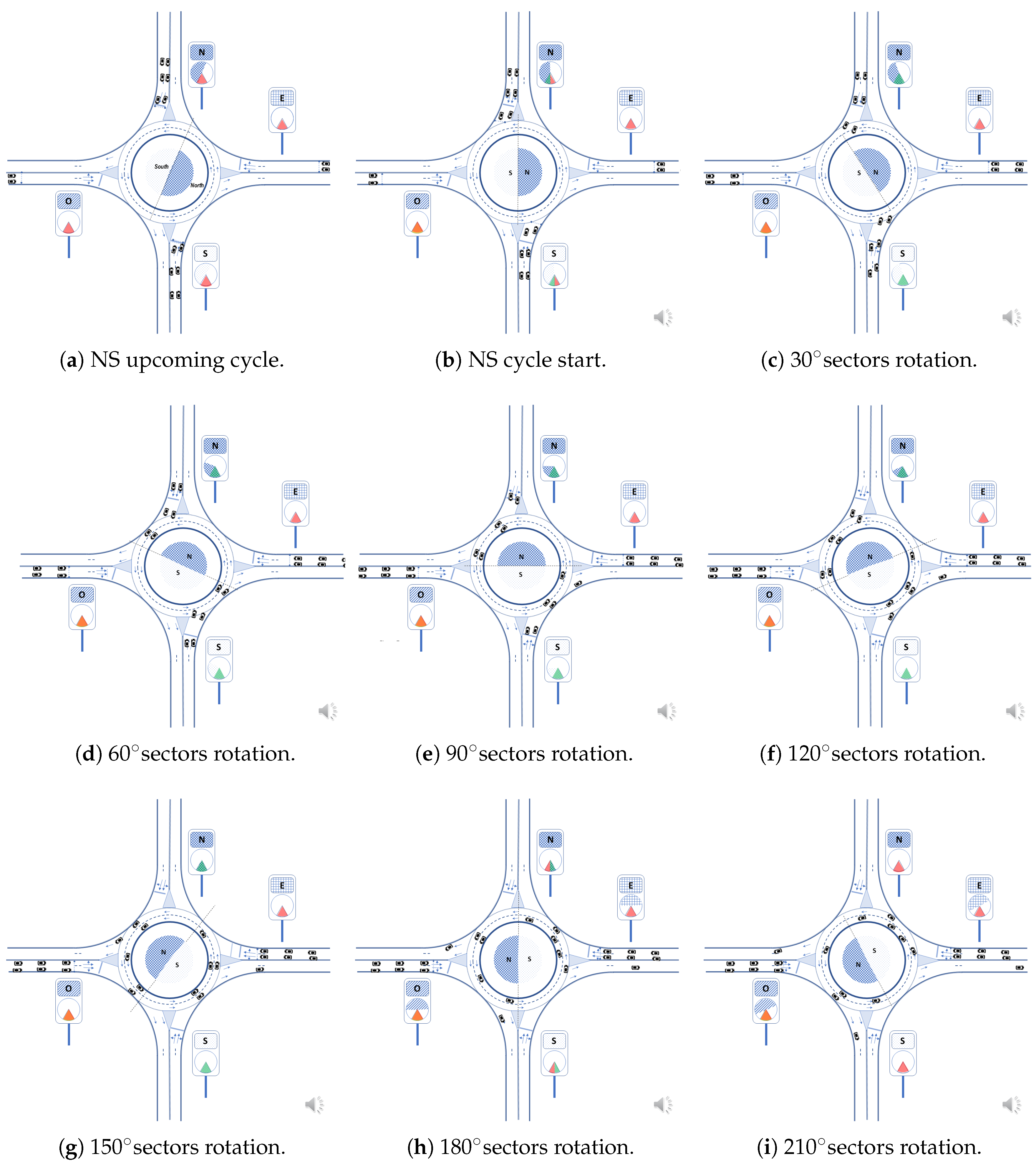
Figure 8 shows the signaling schematically at the instant when the ring and the illuminated panels indicate the immediate beginning of the access priority for the north and south accesses, given that their respective semicircular sectors N and S begin to cross the access associated with their respective sectors. Vehicles at the north and south entrances may, therefore, begin to exceed their stop lines.
The stop lines are placed at a certain distance from the roundabout (backstops), so that, in the event of forced arrest due to not having priority, vehicles can reach the speed of movement in the roundabout upon reaching it.
Figure 8b shows the lower sector with its green left part (v), informing the north and south accesses’ vehicles that they have access priority. This lower sector continues to be shown in green until
Figure 8h, in which it is close to disappearing, as the semicircular sectors of north and south priority pass through their respective entrances.
The vehicles of north and south accesses reach the edge of the roundabout and freely circulate during their sector’s duration, having finished their access priority in
Figure 8g and thus ceasing to have access to the roundabout.
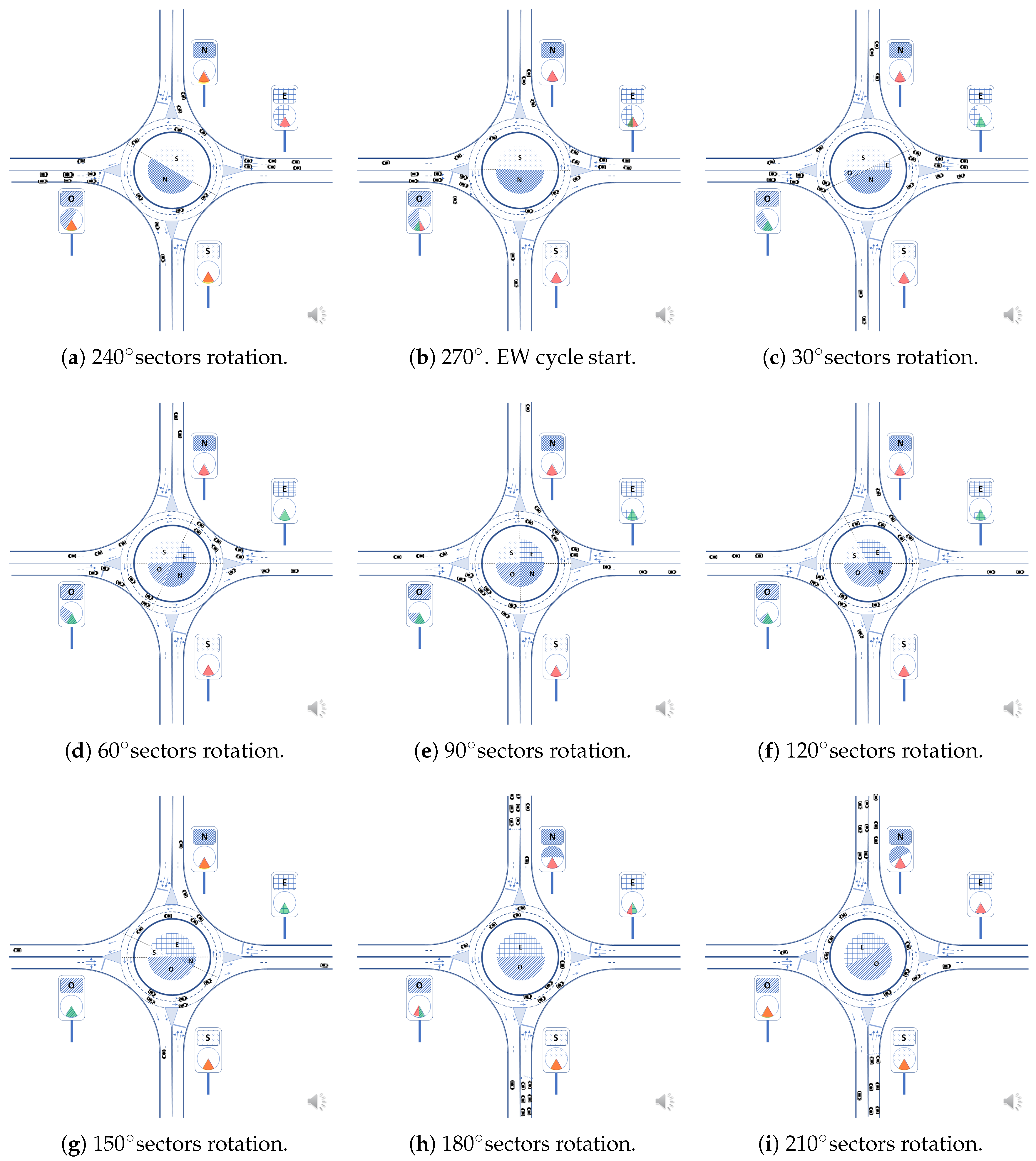
Figure 8i shows the starting time of the priority for the accesses with the east and west sectors’ appearance when the east and west sectors reach the lower sectors of the east and west accesses, in the vertical light panels.
In
Figure 9a–g it can be seen how the lower sector in the east and west panels lights up green starting from the left side
Figure 9b, coinciding with the passage of the east sector through the lower sector and ending on its right side
Figure 9h. In the central circle, the most advanced radius in the direction of rotation of the south and north sectors is then fixed in the west and east directions, respectively, stopping its rotation. However, the most backward radius of the north and south sector continues to rotate. Thus, the amplitude of these sectors begins to decrease. In the space created by this decrease, the east and west sectors appear and grow gradually with the general turn of traffic and to the same extent that the North and south sectors contract. The east and west access vehicles begin to access the roundabout when they have priority, i.e., their priority sector passes in front of their access.
Figure 9i shows how the last vehicles coming from north and south have already left from the west and the east, respectively (the maximum allowed turn is 270
; changes of direction are prohibited in this specific roundabout implementation). The east and west light sectors gradually increase until they reach their maximum amplitude (180
in this implementation).
Figure 9i shows the end of the priority of the east and west accesses and
Figure 10a,b shows when the north and south vehicles arrive and begin to have the right of way. The cycle repeats indefinitely.
The described sequence provides maximum roundabout utilization but may need some allowance for human failures in adapting to the roundabout circulating discipline (i.e., circulating at the recommended speed and leaving the roundabout maximum at a 270 turn). Then it seems reasonable, at least when starting to operate a revolving roundabout, to foresee a slack or “void” sector at the end of the signaling cycle to ensure that all vehicles abandon the roundabout and that next cycle starts without disturbances that could affect the circulating speed. An extra phase period of duration between 90 and 180 would provide a margin for vehicles to leave the roundabout. This would be a "mandatory emptying: phase. It would also allow u-turns to vehicles that did not leave the roundabout at the maximum 270 turn allowed. The reduction of capacity of this sector (directly proportional to cycle lengthening) seems acceptable. In the sequence shown, to implement an extra 180 sector it would be necessary to increase the inter-platoon staggering accordingly.
5. Evaluation
Synchronous roundabouts are much more regular and predictable in operation than conventional ones and do not require drivers’ decisions to enter the roundabout. Due to this regularity and predictability, we first evaluate roundabout capacities analytically. We evaluate one example of implementation, among the many alternative sector sizes, rotation speeds and signaling sequence arrangements. For simplicity, we assume equal traffic in all accesses and use (except during priority transitions) only two simultaneous sectors of 180 maximum amplitude. The vehicle turns at the roundabout are only allowed up to 270.
The important parameters are closely interrelated and affect its capacity: radius, vehicle separation (gap in seconds or distance) and roundabout rotation period and average linear speed of the rotating sectors). The ranges considered practical and used for this evaluation are as follows:
Rotation period: 10 to 22 s (5 to 11 s half-periods).
Angular rotation: derives directly from the rotation period (6.26 radians per turn): from 0.63 to 0.29 rad/s.
Radius: from 10 to 50 m (measured at the separation of the two lanes).
Linear speeds at roundabouts: 23 to 51 km/h.
These ranges are a first approach that would likely evolve with the drivers’ practice and other improvements. Some parameter impacts are easy to compute: an increase of 20% in the rotation period produces the same reduction in capacity, excluding platoon lengths truncation effects (although they can be compensated between accesses).
The necessary time (or maximum transit time) for a platoon crossing is two semi-periods of roundabout signaling rotation: one semi-period is used by the platoon heads located at the entrance of the roundabout to cross the roundabout completely and occupy the full semicircle, and the second is used by the platoon to exit the roundabout. If speed is constant, the lengths should be equal. Some guard time is needed at both ends (especially at the platoon tail) to ensure smoothness. For example, if the priority period (semicircle rotation) duration is 6 s, the first 6 s are used by the platoon heads to get close to the roundabout exit, and the six additional seconds will be used by the platoon to leave the roundabout.
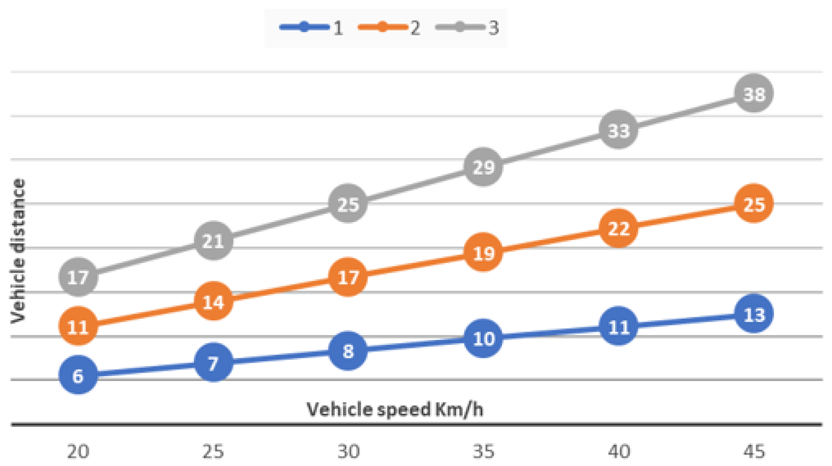
5.1. Inter-Vehicle Distance
The most critical aspect that impacts roundabout capacity is the distance between vehicles (follow-up headway in seconds or meters). In conventional roundabouts, this distance is significant because the follow-up time (
= 2.7 s) includes the delays involved in human reaction to follow the preceding car when it starts. If we reduce
in one second by avoiding stops and speed changes, the corresponding inter-vehicle distance may be reduced.
Figure 11 shows typical values for inter-vehicle distances versus time gaps in seconds. In [
10], the follow-up headway (time between passing) vehicles in standard roundabouts has been recently reduced to approximately 2.6 s, including the first vehicle’s length, which takes about 0.5 s to pass.
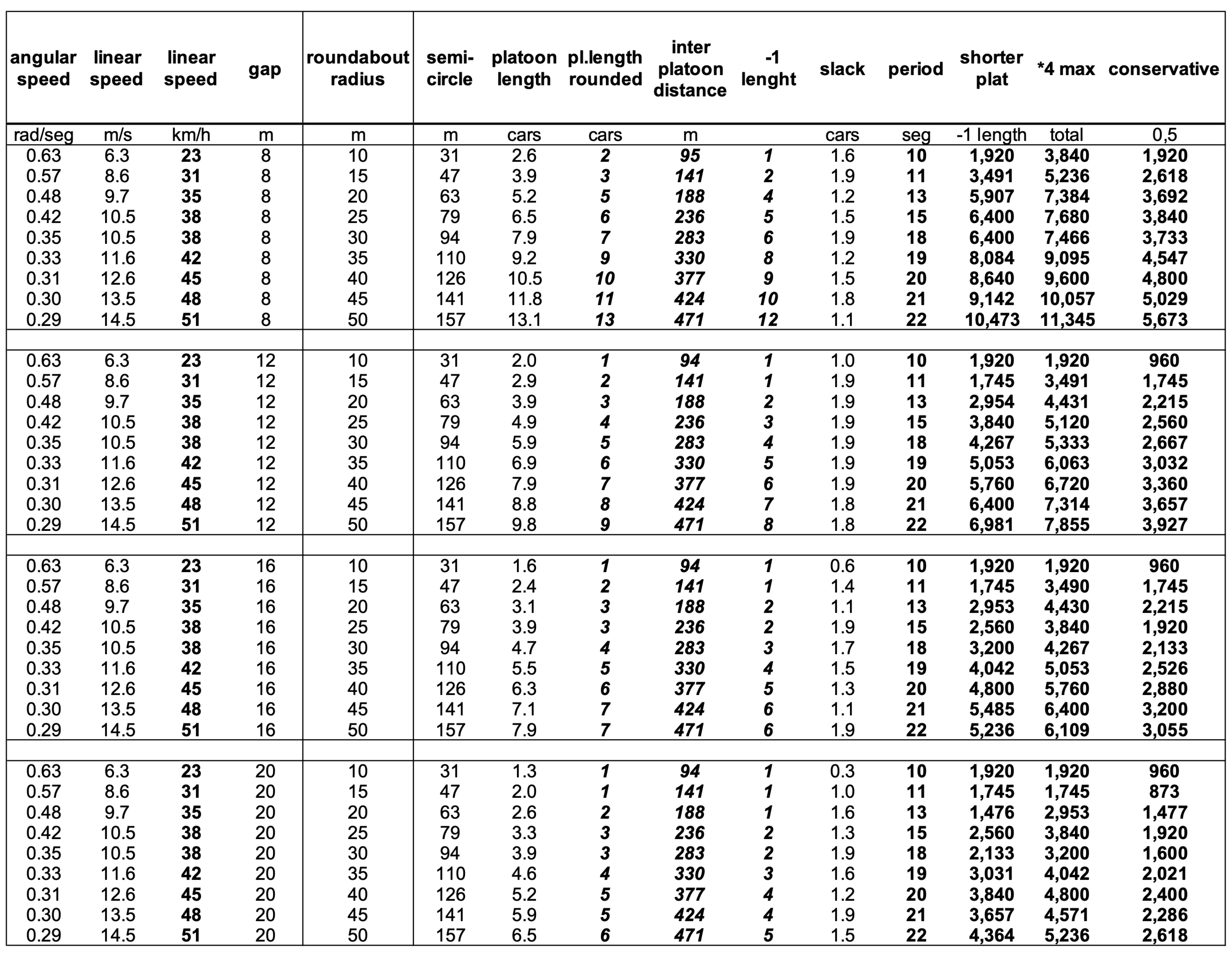
5.2. Calculation of the Maximum Capacity of a Roundabout
The maximum theoretical capacity of a rotary roundabout is obtained by multiplying the number of cars that can cross the roundabout in one signaling cycle, multiplied by the number of cycles possible in one hour, i.e., 3600 s divided by the total (N–S and E–W) signaling period duration in seconds.
More precisely, for the implementation described above, every three-fourths of a turn, two accesses fill and then empty their semicircle sectors, and so two platoons cross the roundabout. Afterward, the orthogonal pair of accesses does the same. During the fourth cycle, the orthogonal pair of accesses starts entering the roundabout, requiring 1.5 turns per complete signaling cycle. All vehicles in platoons cross the roundabout in one and a half rotation period. For a four-accesses two lanes per access roundabout, the formula for maximum capacity is:
where
C is the capacity in passenger car equivalents per hour,
L is the platoon length in number of vehicles and
T is the signaling rotation period. The platoon length is obtained by dividing the semicircle length modulo the sum of vehicle length (4 m) plus inter-vehicular (gap) distance. In synchronous roundabouts, the uniform speed in accesses and inside the roundabout gives the drivers confidence in safety (a quasi-stationary scenario), and gaps can be significantly reduced. Besides, the driver must only maintain the platoon speed and distance, much more comfortable than entering conventional roundabouts, that require a gap estimation based on other vehicle speeds and distances. Gaps of 1–1.5 s between vehicles seem realistic to achieve as the relative speed between platoon vehicles entering the roundabout is very small. In line with this assumption, we select distances from 8 m (equivalent to two car lengths) to 20 m (equivalent to five car lengths) for the capacity calculations.
Figure 12 shows the capacities calculated for combinations of roundabout radius, inter-vehicle distances and linear speed. Rotating periods are adapted to the roundabout radius to obtain a suitable linear speed for its radius.
The roundabout rotation periods have been chosen to result in a linear speed in line with a realistic linear arrival speed at accesses depending on their diameter (25 to 45 km/h). Increasing the rotation period reduces the capacity in the same proportion. The three capacity columns are computed as follows: the maximum capacity column (center) is obtained assuming full platoons of spaced vehicles at the distance gap selected (8, 12, 16 or 20 m) with the maximum length allowed physically. However, the left column is more conservative. It assumes that the length of the platoons is one unit less than the maximum possible (if maximum length is equal or greater than 2), to take into account multiple factors preventing platoon optimization, and the right column is the most conservative approach: it assumes that the practical capacity is half of the maximum capacity calculated.
Figure 13 represents the maximum capacities results from the previous table (middle) for different roundabout radius and inter-vehicle distances. The coincidences in capacity values result from the granularity introduced by the fixed platoon (equal in all accesses) when the platoon length is the same for two inter-vehicle distances. The rotation period for the bigger roundabouts is larger, so the capacity is lower than the smaller radius roundabout. The performance steps are significant because an increase of just one vehicle in the length of platoons means 2 × 4 = 8 more vehicles crossing in 1.5 roundabout periods (e.g., 24 s) 1200 pce/h theoretical maximum. In real roundabouts, traffic is not equal in all accesses, and sector duration may be adapted to traffic intensities. These cases are subject to future work.
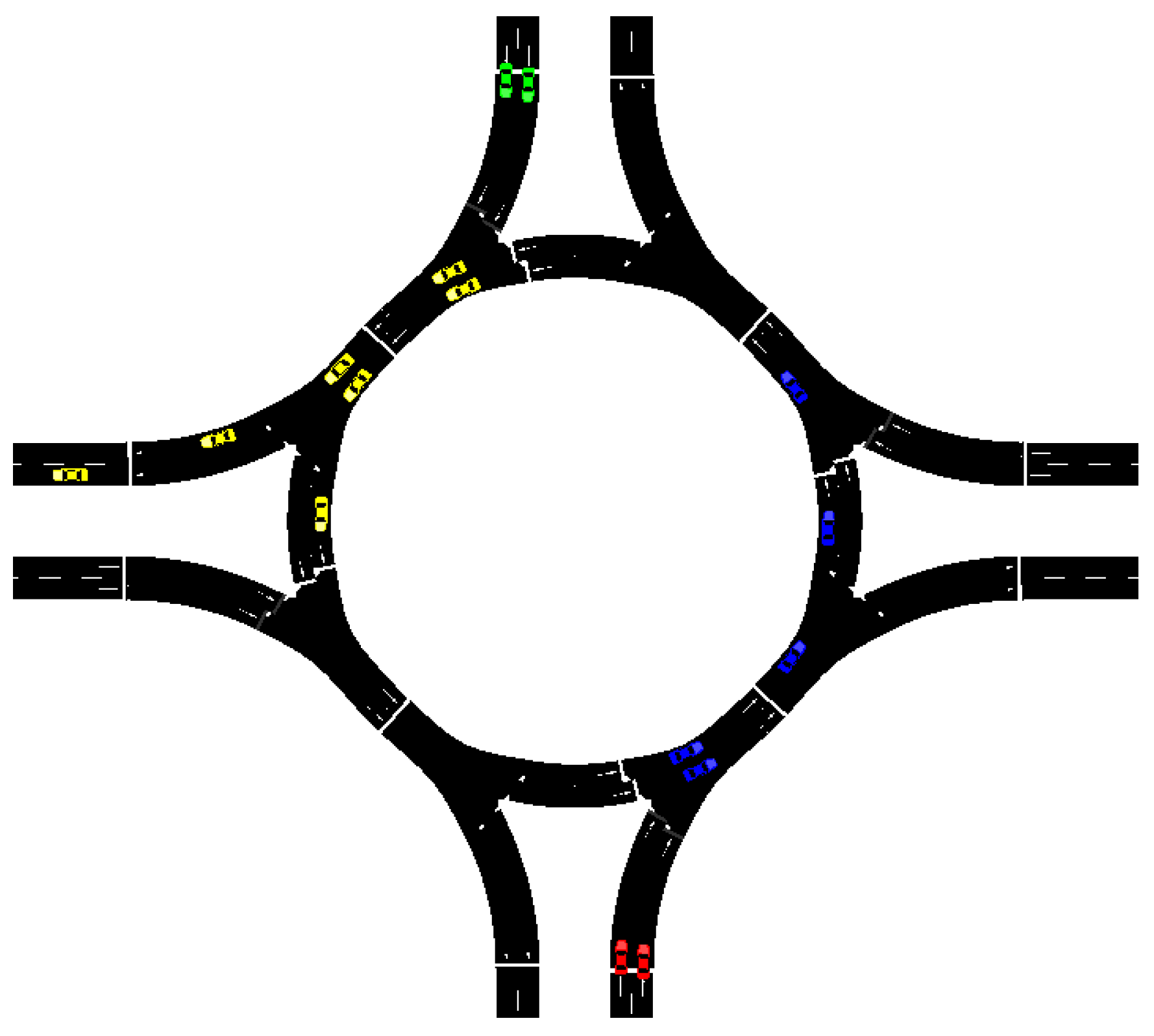
5.3. Experiments
In addition to our numerical analysis, we implemented our approach in the traffic simulator SUMO [
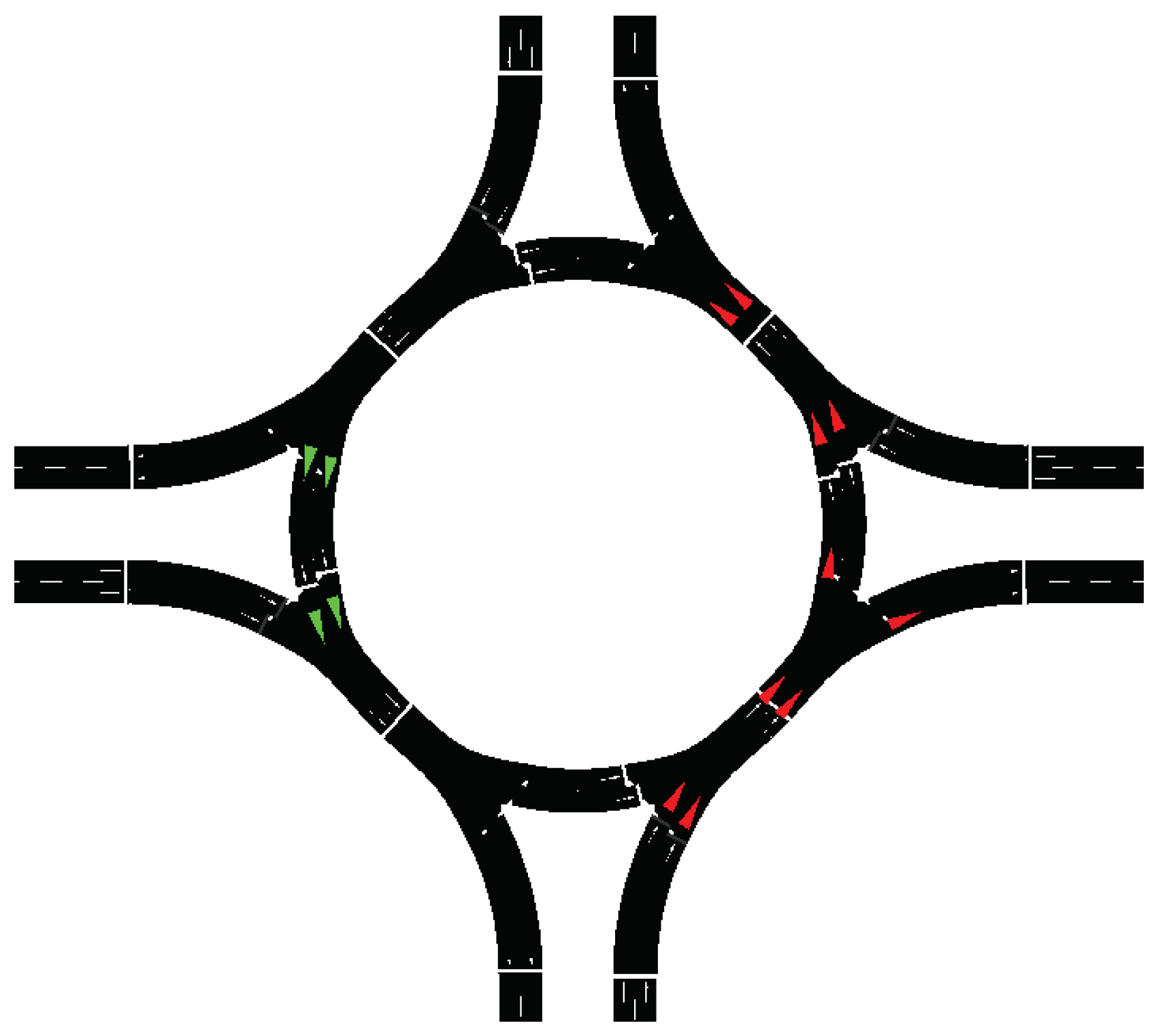
11] to compare it with a non-controlled roundabout with four entries and exits under realistic traffic conditions. A snapshot from the simulation in SUMO is shown in
Figure 14. In this figure, we can see the standard case for balanced traffic, in which the vehicles from the north and the south arrive just after their entry has been cleared from the vehicles starting in west and east.
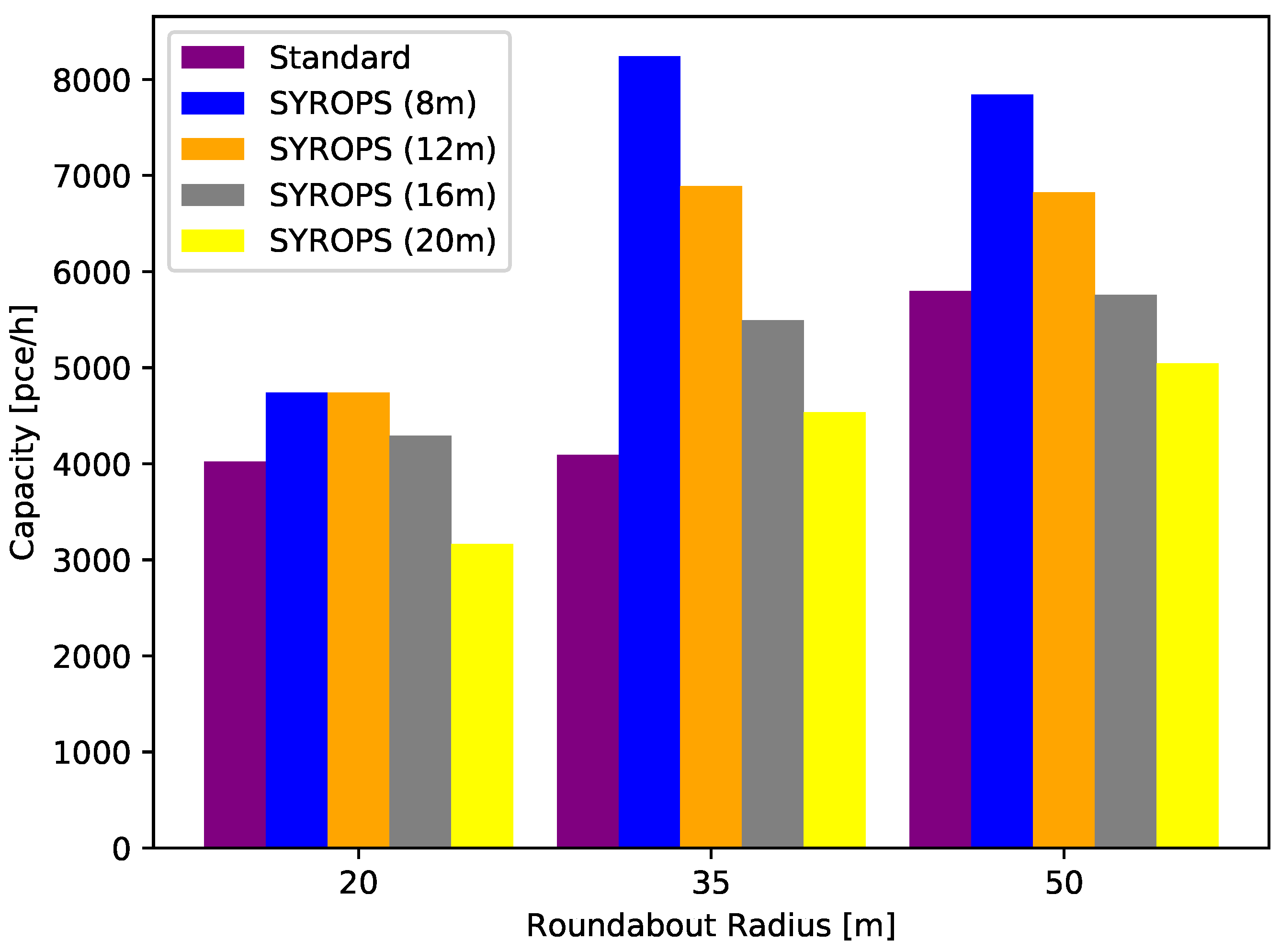
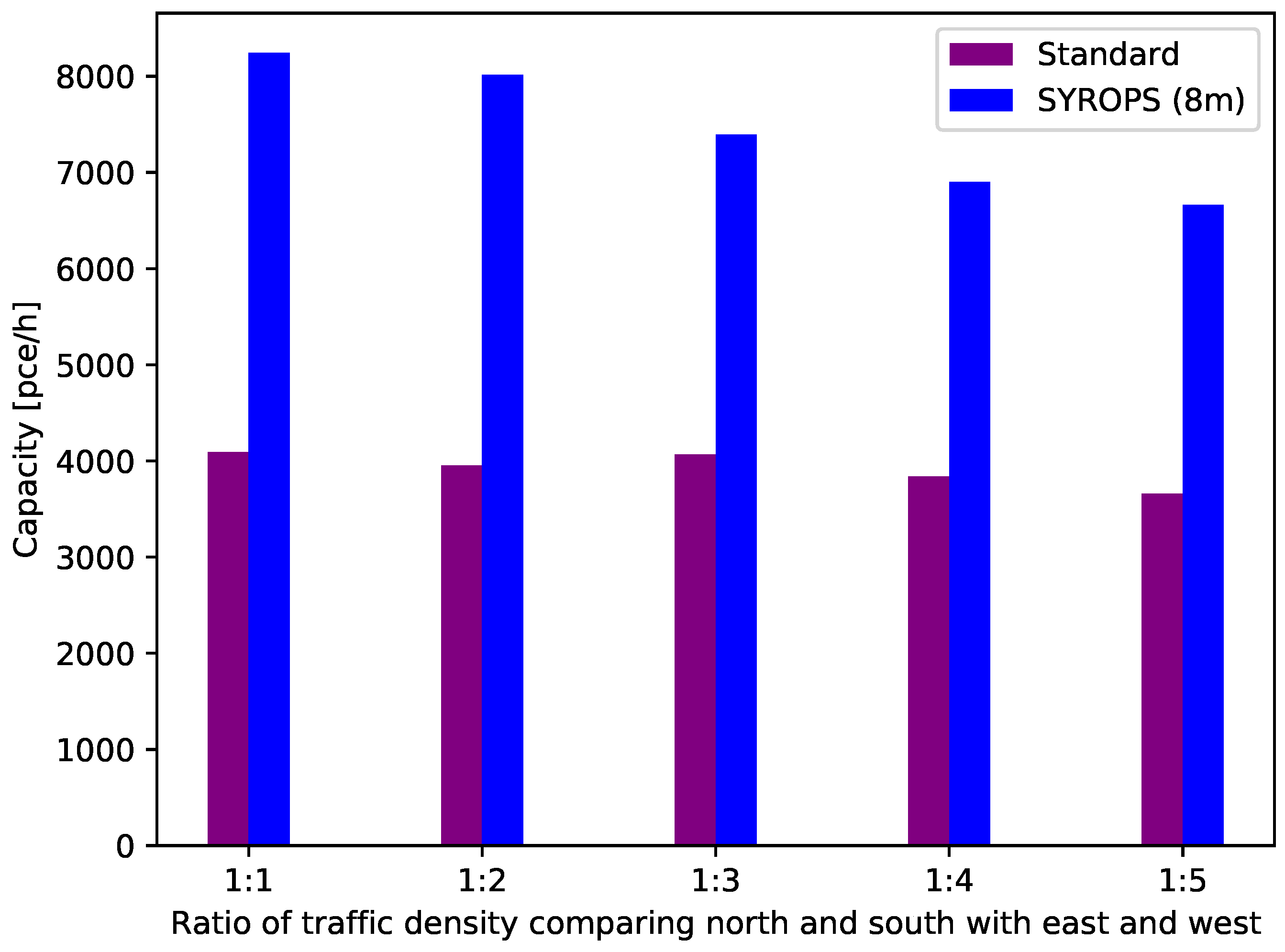
The results of this comparison regarding the number of vehicles that can traverse the roundabout in one hour are shown in
Figure 15. The SYROPS mechanism is implemented was SUMO using traffic lights. The values in meters shown between brackets after the SYROPS label correspond to the safety distance between vehicles that is used by SUMO. For the standard roundabouts, a safety distance of 15 m is used. Thus, for SYROPS (16 m) and SYROPS (20 m), the distance between the vehicles is higher than in the standard roundabouts approach. These two correspond to a roundabout controlled with lights but without the benefits of platooning. For these two cases, as expected, the performance decays and is comparable or slightly better than the performance of the standard roundabout. For this simulation, the incoming traffic is assumed to be evenly distributed. Additionally, we can see that our approach’s improvement compared to a standard roundabout is comparably small for small roundabouts and increases drastically for a large roundabout. This behavior is caused by a smaller number of vehicles in small roundabouts, which decreases the number of potential conflicts. Additionally, we can observe that the roundabout capacity generally increases with increasing size of the roundabout due to the increased speed of the vehicles. Thus, the number of vehicles is relatively constant between 35 and 50 m, which differs from our analytical results. This difference is justified by SUMO’s vehicle behavior, which prevents vehicles from entering the roundabout if another vehicle with priority is nearby. We can also observe that the roundabout capacity decreases with increasing inter-vehicle distance, which is expected as fewer vehicles will be driving in a platoon, and thus can traverse the roundabout per cycle.
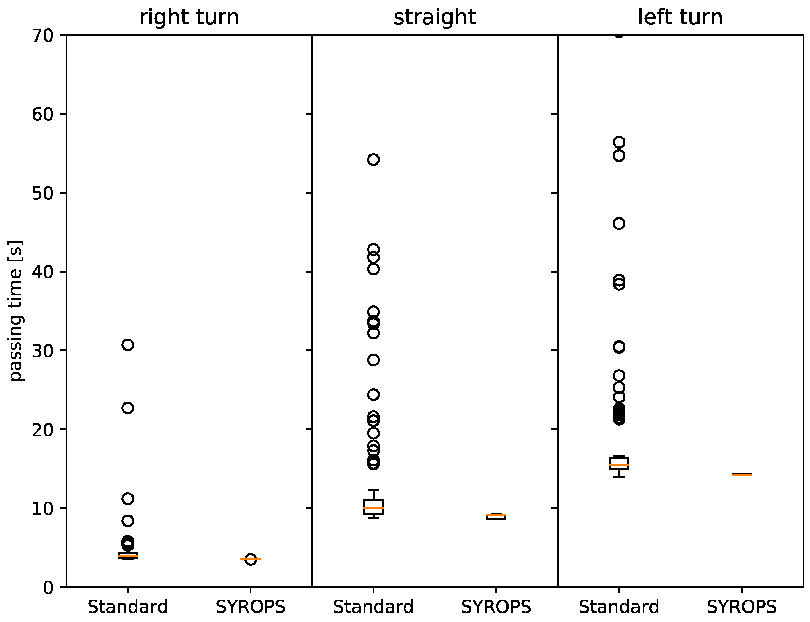
The time a vehicle spends in a roundabout 35 m in diameter is shown in
Figure 16. In this figure, we differentiate the different turn types, where a right turn refers to the vehicle taking the first exit, straight to the second and left to the third. We can observe a drastic improvement in vehicle passing time for all of the three turn types. An interesting prospect is that the right turn’s improvement is smaller than for straight and left turns, as the number of potential conflicts is very low, and the path is very short for vehicles making a right turn. Thus, the median time spent in the roundabout is not improved, while only the 75th percentile is improved by
. When looking at straight, we also observe an improvement of
of the 75th percentile, and a small improvement in the median by
, which is caused by the increased number of possible conflicts. SYROPS prevents said conflicts. Thus, the time spent in the roundabout becomes very predictable and has little fluctuation, which is suitable for having a constant and accident-free traffic flow. For the left turn, the improvement is very drastic, as the number of possible conflicts is the highest among all directions. Thus, we can see an improvement of
in the median time, and an
decrease in the worst case. The overall average time spent of a vehicle in the roundabout independent of the direction is improved by
.
5.4. Signaling Dynamics and Variants for Unbalanced Traffic
Traffic in roundabouts is often unbalanced. SYROPS signaling can adapt the duration of sectors to different traffic intensities at the accesses and use either different platoon lengths or just signal two platoons in consecutive phases (e.g., two phases of N–S sectors per one phase E–W). The use case of unequal traffic intensities at accesses is typical in practice. There is a dominant traffic direction in many roundabouts, and a daily change oscillation of the dominant traffic (e.g., commuters going and returning from work or shopping).
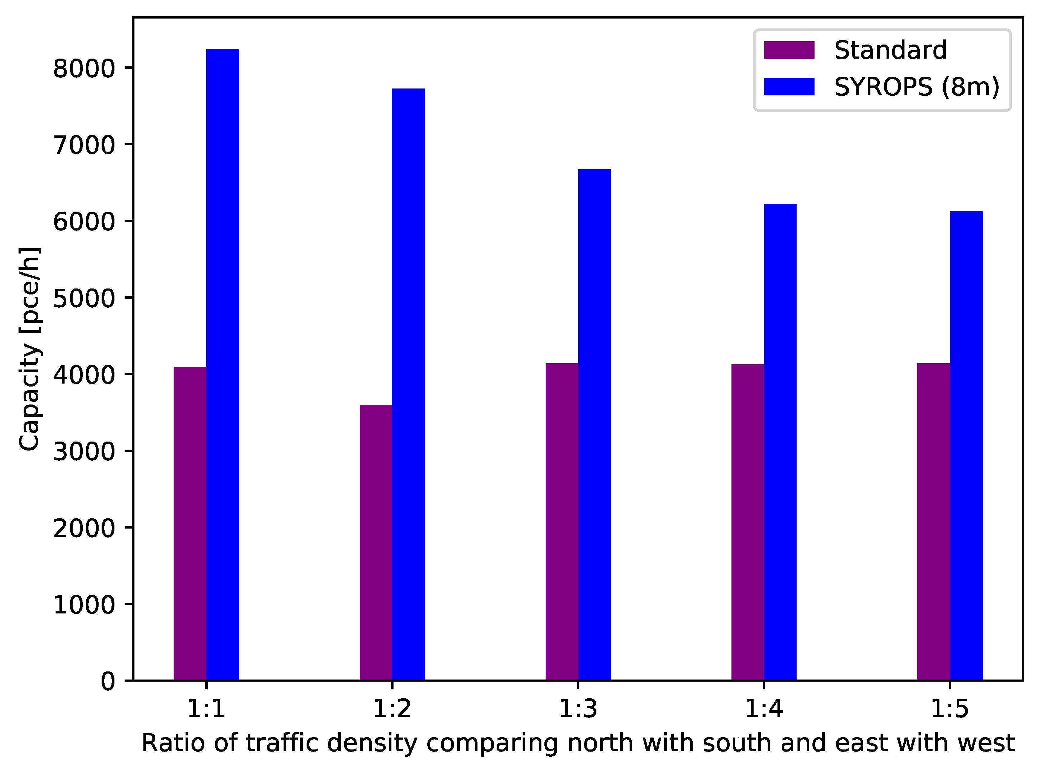
In the following, we present comparative SUMO simulation results to show the performance of our approach in these scenarios versus the standard roundabouts (yield type). In
Figure 17, we analyze how a unbalance in the opposite traffic flows (e.g., south is higher than north, east is higher than west) affects the capacity performance of our approach compared to standard roundabouts.
Our approach compensates for this traffic unbalance by increasing the number of vehicles that may pass from one direction (e.g., north) while decreasing the number of vehicles that may pass from the opposite direction (e.g., south), as also shown in
Figure 18. For SYROPS with platooning, we observe that there is a quite significant reduction of traffic flow compared to a balanced traffic. However, even for highly unbalanced traffic, SYROPS still outperforms standard roundabouts by approximately
.
We also simulated traffic unbalance between the two traffic axis (e.g., there is a much higher traffic flow between north and south than between west and east) in
Figure 19. Our approach compensates for this traffic unbalance by adding an additional green phase for the route of high traffic density (e.g., south and north), while skipping skipping one green phase for the barely trafficked route (e.g., east and west). For SYROPS with platooning, we observe that there is a quite significant reduction of traffic flow compared to a balanced traffic, which is smaller compared to the other type of unbalance, however. Similarly, we outperform the standard roundabout significantly.
5.5. Allowing U-Turns
An important signaling variant allows u-turns (i.e., 360 degrees turns maximum allowed instead of only 270), at the cost of increasing the phase duration by an additional 90
sector rotation per access (360
instead of 270
) to complete the turn, plus another 90
inactive sector where no entrances are allowed. This inactive sector adds safety to the roundabout and gives way for distracted drivers exceeding U-turns to leave the roundabout compulsively at the next 90
turn if presence is sensed in this 90
sector. The roundabout’s total cycle time would now be 28/8 turns, a maximum of 3.5 rotation periods instead of 1.5 for the 270 degree version. Nevertheless, six 1/8 th rotations are void (no vehicle entrance). If the signaling skips these rotations, the period would be 22/8 = 2.75 periods. The sequence is shown in
Figure 20. Note that north and south sectors reach north and south, and afterwards, no traffic is allowed. Part of this time can be used as a safeguard to empty the roundabout.
This increase in cycle time would decrease proportionally the capacity of the roundabout, multiplying it by a factor of 1.5/2.75 = 0.54, a 46% reduction. If a higher capacity is needed, the 90 void sector may be skipped, and E–W entrance signaled just after north and south closing, which should be signaled smoothly and carefully in order to prevent drivers’ surprise. The “U-turn allowed” signaling sequence seems advisable for new deployments until the drivers get familiar with the revolving roundabouts procedures.
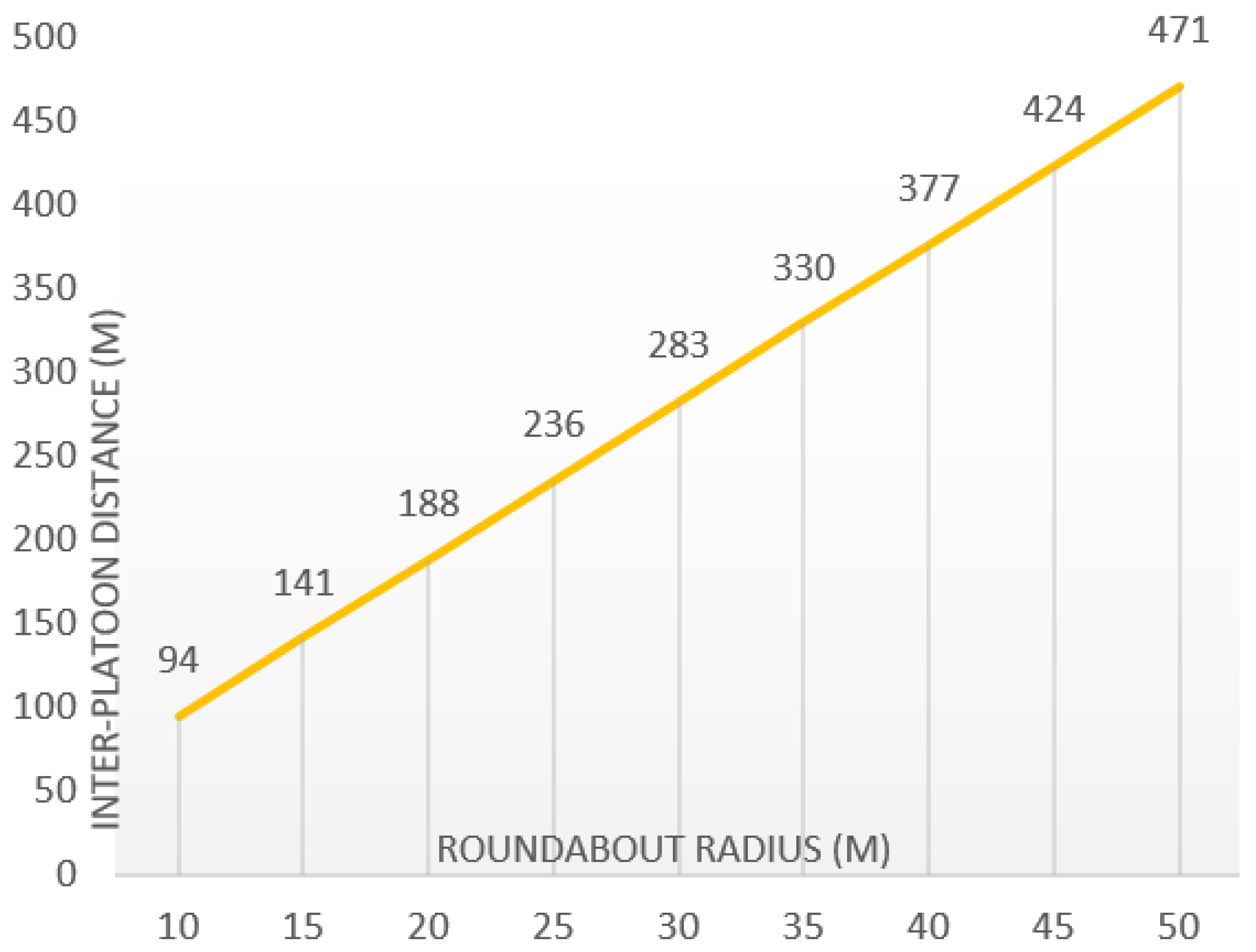
5.6. Inter-Platooning Distances
The distance between platoons is, assuming constant speed, the roundabout’s linear speed multiplied by the signaling cycle duration.
Figure 21 shows the inter-platoon distances to be maintained by the moving platoon head signals.
5.7. Traffic Overload
Synchronous revolving roundabouts prevent congestion through admission control. The platoon headers act as limiters of vehicle flow flowing through the roundabout accesses. Then, the potential queues will appear far from the roundabout. In case of transient excess of traffic, vehicles will accumulate in the road before the platooning zone of priority extended for the accesses. This aspect must be taken into account in the design.
5.8. Pedestrians Traffic
Pedestrian traffic usually significantly impacts roundabout performance and safety, and a multiplying coefficient factor is used [
23]. For SYROPS roundabouts, a pedestrian can safely cross the incoming access just after a platoon has passed, and pedestrian signals should adapt to it. If the phases of the pedestrian lights in the incoming and outgoing directions of every access are independent, they can best adapt to it. Multi-level pedestrian signaling concepts as in [
24] could be applied. The crossing of the outgoing part of the access should use time-slots of the signaling cycle with low traffic probability, e.g., transitions between exiting traffic from different accesses. The design of sectors duration may also take this into account to create these gaps.
5.9. Roundabout Capacities at HCM 6th Edition
The USA Highway Capacity Manual includes a section for roundabout capacity estimation [
10]. The model can be viewed both as an empirical (exponential regression) model and a gap-acceptance model. The final equation for capacity recommended in HCM2016 section A.2.3 [
10], using the recommended values for headway and follow-up, is:
where
Qe is capacity in pce/h passenger vehicles per hour and
Qc the conflicting traffic. Assuming uniform traffic in the four accesses, we can estimate the maximum capacity of a rotary roundabout (with maximum permitted rotation of 270
) as follows. For a uniformly distributed traffic, Figure 1 in [
23] gives a total of 800 + 700 = 1500 pce/h maximum. The application of this value to all entries simultaneously is questionable, as the examples do not consider perfectly balanced traffics [
23] and the simulation scenarios with a total absolute maximum capacity of 1830 pce/h. [
25]. Comparing this value with our analytical results, it would correspond to midsize roundabouts with 20 m inter-vehicle distance, quite in the low range of capacities. A key point to be further studied is that in the HCM model, the service levels will likely degrade much earlier with increasing conflicting traffic than in SYROPS.
6. Future Work
The detailed design of signalling for typical patterns of unbalanced traffic is a key point for further study (i.e., doubling the frequency of sectors of the main traffic direction or shorten the sector duration of the direction with lower traffic). Additionally, the perception and design improvement of the new light signals proposed, the emergency mode of operation and transitions between operating modes (standard, SYROPS, emergency), the static and dynamic signaling adaptation to traffic unbalances. Another important aspect to devise is the integration of synchronous roundabouts in the existing asynchronous traffic network, although with and increasing number of isochronous sections with limited (i.e., uniform) speed (tunnels, roundabouts, urban sections, etc.). We also plan to develop a comparison analysis of SYROPS with existing approaches based on the optimization of crossing patterns in intersections, like those proposed in [
17], which are thought to be applied in autonomous vehicle environments.
7. Conclusions
Roundabouts with rotating priorities open a new path for research on roundabout evolution incorporating most technologies (sensors, V2X, IoT, scene interpretation, Intelligent Infrastructures, smartphones, CAVs), preserving compatibility with human-driven vehicles. The analytical evaluation and SUMO simulations show lower delay and minimal delay variations, and higher capacities than conventional roundabouts. By eliminating the conflict points and subsequent speed changes, safety is also improved through driving smoothness. Drivers do not have to find a suitable gap and accelerate to enter; they are only required to enter the roundabout in the lane corresponding to their exit and follow the platoon or head of platoon signal and to Signaling sequences adapt dynamically to traffic unbalances and daily fluctuations and may alternate between a standard operation or synchronous mode with heavy traffic. Low delay variation will probably provide high levels of service (LOS). Adopting SYROPS roundabouts is not an easy task: as it happened with current roundabouts, the synchronous rotating priorities roundabout concept requires a learning period by the vehicle drivers and also a signaling design well adapted to human perception. Although the constant speed approach simplifies roundabout crossing, the perceptual aspects must be evaluated together with the traffic dynamics. Simulations and virtual reality platforms offer an excellent set of tools for it.
Author Contributions
Conceptualization, G.I. and M.A.L.-C.; methodology, G.I. and T.M.; software, T.M.; validation, T.M. and D.L.-P.; investigation, G.I., T.M., M.A.L.-C. and D.L.-P.; resources, G.I.; data curation, G.I. and D.L.-P.; writing—original draft preparation, G.I.; writing—review and editing, M.A.L.-C. and D.L.-P.; supervision, G.I.; project administration, G.I.; funding acquisition, G.I. All authors have read and agreed to the published version of the manuscript.
Funding
This work has been co-funded by a grant from Comunidad de Madrid through Project TAPIR-CM (S2018/TCS-4496), and by the German Research Foundation (DFG) in the Collaborative Research Center (CRC) 1053—MAKI.
Acknowledgments
Thanks to Antonio Fernandez-Anta from IMDEA Networks Spain for his unconditional support and suggestions.
Conflicts of Interest
The authors declare no conflict of interest.
References
- Circus (Bath). Available online: https://en.wikipedia.org/wiki/Circus_(Bath) (accessed on 5 May 2020).
- Retting, R.; Persaud, B.; Garder, P.; Lord, D. Crash and Injury Reduction Following Installation of Roundabouts in the United States. Am. J. Public Health 2001, 91, 628–631. [Google Scholar] [PubMed] [Green Version]
- Rodegerdts, L. Roundabouts in the United States; Transportation Research Board: Washington, DC, USA, 2007; Volume 572. [Google Scholar]
- Akccelik, R. Roundabout Metering Signals: Capacity, Performance and Timing. Procedia-Soc. Behav. Sci. 2011, 16, 686–696. [Google Scholar] [CrossRef] [Green Version]
- Vasconcelos, L.; Silva, A.B.; Seco, A.M.; Fernandes, P.; Coelho, M.C. Turboroundabouts: Multicriterion Assessment of Intersection Capacity, Safety, and Emissions. Transp. Res. Rec. 2014, 2402, 28–37. [Google Scholar] [CrossRef] [Green Version]
- Magic Roundabout (Swindon). Wikipedia. 2020. Available online: https://en.wikipedia.org/w/index.php?title=Magic_Roundabout_(Swindon)&oldid=954183430 (accessed on 10 May 2020).
- Noor-A-Rahim, M.; Liu, Z.; Lee, H.; Ali, G.G.M.N.; Pesch, D.; Xiao, P. A Survey on Resource Allocation in Vehicular Networks. IEEE Trans. Intell. Transp. Syst. 2020. [Google Scholar] [CrossRef]
- Liang, L.; Li, G.; Xu, W. Resource Allocation for D2D-Enabled Vehicular Communications. IEEE Trans. Commun. 2017, 65, 3186–3197. [Google Scholar] [CrossRef]
- Azimi, R.; Bhatia, G.; Rajkumar, R.R.; Mudalige, P. STIP: Spatio-Temporal Intersection Protocols for Autonomous Vehicles. In Proceedings of the 2014 ACM/IEEE International Conference on Cyber-Physical Systems (ICCPS), Berlin, Germany, 14–17 April 2014; pp. 1–12. [Google Scholar]
- Highway Capacity Manual, Sixth Edition: A Guide for Multimodal Mobility Analysis. Available online: http://www.trb.org/Main/Blurbs/175169.aspx (accessed on 16 October 2020).
- Lopez, P.A.; Behrisch, M.; Bieker-Walz, L.; Erdmann, J.; Flötteröd, Y.P.; Hilbrich, R.; Lücken, L.; Rummel, J.; Wagner, P.; Wießner, E. Microscopic Traffic Simulation Using SUMO. In Proceedings of the 2018 21st International Conference on Intelligent Transportation Systems (ITSC), Maui, HI, USA, 4–7 November 2018. [Google Scholar]
- Highway Capacity Manual (HCM 2010). Available online: http://www.trb.org/Main/Blurbs/164718.aspx (accessed on 16 October 2020).
- National Academies of Sciences, Engineering, and Medicine 2010. Roundabouts: An Informational Guide Second Edition; The National Academies Press: Washington, DC, USA, 2010. [Google Scholar] [CrossRef]
- Martin-Gasulla, M.; Garcia, A.; Moreno, A.T. Benefits of Metering Signals at Roundabouts with Unbalanced Flow: Patterns in Spain. Transp. Res. Rec. 2016, 2585, 20–28. [Google Scholar] [CrossRef]
- Fortuijn, L.G.H. Turborotonde En Turboplein: Ontwerp, Capaciteit En Veiligheid; TRAIL Research School: Delft, The Netherlands, 2013. [Google Scholar]
- Traffic Lights Control for Fuel Efficiency. Available online: https://patents.justia.com/patent/20170330456 (accessed on 16 October 2020).
- Azimi, R.; Bhatia, G.; Rajkumar, R.; Mudalige, P. Ballroom Intersection Protocol: Synchronous Autonomous Driving at Intersections. In Proceedings of the 2015 IEEE 21st International Conference on Embedded and Real-Time Computing Systems and Applications, Hong Kong, China, 19–21 August 2015; pp. 167–175. [Google Scholar] [CrossRef]
- Azimi, R.; Bhatia, G.; Rajkumar, R.; Mudalige, P. V2v-Intersection Management at Roundabouts. SAE Int. J. Passeng. Cars-Mech. Syst. 2013, 6, 681–690. [Google Scholar] [CrossRef] [Green Version]
- Chen, B.; Sun, D.; Zhou, J.; Wong, W.; Ding, Z. A Future Intelligent Traffic System with Mixed Autonomous Vehicles and Human-Driven Vehicles. Inf. Sci. 2020, 529, 59–72. [Google Scholar] [CrossRef]
- Vehicle to Everything. Available online: https://en.wikipedia.org/wiki/Vehicle-to-everything (accessed on 5 June 2020).
- ETSI. Intelligent Transport Systems (ITS); Vehicular Communications; Basic Set of Applications; ETSI: Valbonne, France, 2014. [Google Scholar]
- Masi, S.; Xu, P.; Bonnifait, P. Adapting the Virtual Platooning Concept to Roundabout Crossing. In Proceedings of the 2018 IEEE Intelligent Vehicles Symposium (IV), Changshu, China, 26–30 June 2018; pp. 1366–1372. [Google Scholar]
- Akccelik, R. An Assessment of the Highway Capacity Manual Edition 6 Roundabout Capacity Model; Transportation Research Board: Green Bay, WI, USA, 2017. [Google Scholar]
- Xu, H.; Zhang, K.; Zheng, Q.; Yao, R. Multi-level pedestrian signalisation at large four-leg roundabouts. IET Intell. Transp. Syst. 2018, 12, 838–850. [Google Scholar] [CrossRef]
- HCM 6th Edition: Roundabout Calculation Changes. Available online: http://www.mikeontraffic.com/hcm-6th-edition-roundabout/ (accessed on 5 September 2020).
Figure 1.
An example of a synchronous revolving roundabout with rotating priorities and staggered platoons.
Figure 1.
An example of a synchronous revolving roundabout with rotating priorities and staggered platoons.
Figure 2.
Conflict points in a standard roundabout [
5].
Figure 2.
Conflict points in a standard roundabout [
5].
Figure 3.
SYROPS roundabout signaling arrangement.
Figure 3.
SYROPS roundabout signaling arrangement.
Figure 4.
Block diagram of roundabout control.
Figure 4.
Block diagram of roundabout control.
Figure 5.
Synchronous rotating priority sectors roundabout (SYROPS) signal.
Figure 5.
Synchronous rotating priority sectors roundabout (SYROPS) signal.
Figure 6.
Platoon start signal with maximum platoon sizes.
Figure 6.
Platoon start signal with maximum platoon sizes.
Figure 7.
End of platoon zone signal.
Figure 7.
End of platoon zone signal.
Figure 8.
North-South (NS) access sequence. (a) shows the upcoming priority period for the north and south accesses. From (b–h), platoons at NS entries have priority. In (i) all entries are closed, and the roundabout empties.
Figure 8.
North-South (NS) access sequence. (a) shows the upcoming priority period for the north and south accesses. From (b–h), platoons at NS entries have priority. In (i) all entries are closed, and the roundabout empties.
Figure 9.
East-West (EW) access sequence. (a,b) show the completion of NS cycle. (b) shows the upcoming priority period for the east and west accesses. From (b–h), platoons at EW entries have priority. In (i) all entries are closed, and the roundabout empties.
Figure 9.
East-West (EW) access sequence. (a,b) show the completion of NS cycle. (b) shows the upcoming priority period for the east and west accesses. From (b–h), platoons at EW entries have priority. In (i) all entries are closed, and the roundabout empties.
Figure 10.
East-West (EW) end of cycle and start of a new NS cycle. (a,b) show the completion of the EW cycle. (b) shows the start of the priority period for the NS accesses. In (c) NS entries are opened.
Figure 10.
East-West (EW) end of cycle and start of a new NS cycle. (a,b) show the completion of the EW cycle. (b) shows the start of the priority period for the NS accesses. In (c) NS entries are opened.
Figure 11.
Inter-vehicle distance vs. gap in seconds and speed.
Figure 11.
Inter-vehicle distance vs. gap in seconds and speed.
Figure 12.
Roundabout capacities.
Figure 12.
Roundabout capacities.
Figure 13.
Maximum roundabout capacities vs. vehicle distances and roundabout radius.
Figure 13.
Maximum roundabout capacities vs. vehicle distances and roundabout radius.
Figure 14.
Snapshot of the simulation. The vehicles in the north (green) and south (red) are arriving just after the vehicles from west (blue) and east (yellow) have passed their respective entries to the roundabout.
Figure 14.
Snapshot of the simulation. The vehicles in the north (green) and south (red) are arriving just after the vehicles from west (blue) and east (yellow) have passed their respective entries to the roundabout.
Figure 15.
Roundabout capacity comparison versus size of the roundabout for standard roundabouts and SYROPS with and without platooning.
Figure 15.
Roundabout capacity comparison versus size of the roundabout for standard roundabouts and SYROPS with and without platooning.
Figure 16.
Roundabout delay per direction of travel for a roundabout radius of 35 m.
Figure 16.
Roundabout delay per direction of travel for a roundabout radius of 35 m.
Figure 17.
Roundabout capacity in vehicles per hour as a function of traffic unbalance ratio from opposing directions (N vs. S, E vs. W).
Figure 17.
Roundabout capacity in vehicles per hour as a function of traffic unbalance ratio from opposing directions (N vs. S, E vs. W).
Figure 18.
Snapshot of the SUMO simulation. Unbalanced traffic north–south. More vehicles from the south (red) and less vehicles from the north (green) enter the roundabout to compensate the traffic unbalance.
Figure 18.
Snapshot of the SUMO simulation. Unbalanced traffic north–south. More vehicles from the south (red) and less vehicles from the north (green) enter the roundabout to compensate the traffic unbalance.
Figure 19.
Roundabout capacity in vehicles per hour depending on the level of unbalance ratio between orthogonal directions (N–S vs. E–W).
Figure 19.
Roundabout capacity in vehicles per hour depending on the level of unbalance ratio between orthogonal directions (N–S vs. E–W).
Figure 20.
Signaling sequence for U-turn allowed variant (360) with one (90) void sector.
Figure 20.
Signaling sequence for U-turn allowed variant (360) with one (90) void sector.
Figure 21.
Inter-platoon distances versus roundabout radius.
Figure 21.
Inter-platoon distances versus roundabout radius.
| Publisher’s Note: MDPI stays neutral with regard to jurisdictional claims in published maps and institutional affiliations. |
© 2020 by the authors. Licensee MDPI, Basel, Switzerland. This article is an open access article distributed under the terms and conditions of the Creative Commons Attribution (CC BY) license (http://creativecommons.org/licenses/by/4.0/).


