Article

Lightweight Modeling Attack-Resistant Multiplexer-Based Multi-PUF (MMPUF) Design on FPGA

1
College of Electronic and Information Engineering, Nanjing University of Aeronautics and Astronautics, Nanjing 211106, China
2
Centre for Secure Information Technologies, Institute of Electronics, Communications & Information Technology, Queen’s University Belfast, Belfast BT3 9DT, UK
*
Author to whom correspondence should be addressed.
Submission received: 14 April 2020 / Revised: 10 May 2020 / Accepted: 13 May 2020 / Published: 15 May 2020
(This article belongs to the Special Issue Cyber Security for Internet of Things)

Abstract

:
Physical unclonable function (PUF) is a primary hardware security primitive that is suitable for lightweight applications. However, it is found to be vulnerable to modeling attacks using machine learning algorithms. In this paper, multiplexer (MUX)-based Multi-PUF (MMPUF) design is proposed to thwart modeling attacks. The proposed design uses a weak PUF to obfuscate the challenge of a strong PUF. A mathematical model of the proposed design is presented and analyzed. The three most widely used modeling attack techniques are used to evaluate the resistance of the proposed design. Experimental results show that the proposed MMPUF design is more resistant to the machine learning attack than the previously proposed XOR-based Multi-PUF (XMPUF) design. For a large sample size, the prediction rate of the proposed MMPUF is less than the conventional Arbiter PUF (APUF). Compared with existing attack-resistant PUF designs, the proposed MMPUF design demonstrates high resistance. To verify the proposed design, a hardware implementation on Xilinx 7 Series FPGAs is presented. The hardware experimental results show that the proposed MMPUF designs present good results of uniqueness and reliability.

1. Introduction

Physical unclonable function (PUF) is a promising lightweight security primitive which uses manufacturing process variations to generate a unique digital fingerprint for an electronic device, e.g., application-specific integrated circuit (ASIC) or field programmable gate array (FPGA). Since the manufacturer cannot estimate or control these variations, PUFs are inherently difficult to clone and providing additional tamper-evident properties. Theoretically, no two outputs of the same PUF designs are identical. The same n-bit input challenge generates a different n-bit response for different devices. Such a security primitive provides several advantages over current state-of-the-art alternatives and allows for higher security protocols and applications, e.g., key storage and device authentication.
Since the first PUF has been published [1], PUF architectures can be broadly categorized into Weak PUFs and Strong PUFs as discussed in [2], based on the size of their CRP space which captures the information about the underlying variation. Weak PUFs have a limited CRP space, and in the extreme case only having a single output. Therefore, they are more suited to applications such as key storage or for seeding a PRNG, where the response never leaves the chip and is only accessed as required. In contrast, Strong PUFs have many possible CRPs, whereby a large number of random challenges will return a random response unique to the challenge, as well as the physical device. Previous research also indicates that the random and unclonable bits of the weak PUF can be used as a key in a secure encryption mechanism, e.g., advanced encryption standard (AES), and accomplish the practical design of a strong PUF. In this case, the input and output to the AES can then be considered to be the CRPs of the strong PUF [3]. A helper data must be used to ensure a 100% reliability for the Weak PUF. However, it has been shown that both the helper data and the AES circuit are vulnerable to side channel attacks (SCAs) [4].
Arbiter PUF (APUF) [5] is one of the most widely studied Strong PUFs. However, it has been successfully broken by machine learning (ML)-based modeling attacks by building up a linear additive delay model for each bit [6]. While some researchers have proposed modifications to improve its resistance to modeling attacks [7,8], however, these have also been broken with a sufficient number of CRPs [9,10]. Moreover, to date, these approaches have only been simulated for application-specific integrated circuit (ASIC) and have not been proven in practice, and they are not suitable for FPGA. While Arunkumar et al. [11] pointed out the properties that designers should consider when designing ML resistant PUF designs, a practical and feasible implementation strategy has not been proven yet. Obfuscating CRPs with some random noise is an efficient method to make mathematical modeling more complex, such that it is difficult for modeling attacks to succeed, e.g., [12,13,14,15].
Since PUFs fit for the lightweight authentications of IoT applications, the excessively increased hardware cost is impractical. On the other hand, the previous attacking techniques assume that an adversary has an unlimited access to PUF structures to collect sufficient training CRPs from the PUF. The adversary can break most of the existing PUF structures if he can obtain enough valid CRPs using advanced methods such as approximate attack [16]. However, recent research in [17] has shown that it is possible to prevent such machine learning attacks by restricting the number of accessed CRPs. To address this challenge, multiplexer (MUX)-based Multi-PUF (MMPUF) design is proposed to thwart modeling attacks. The proposed design uses a weak PUF to obfuscate the challenge of a strong PUF. The most important property of the proposed PUF is that it can achieve the highest resistance to ML attacks with the lowest hardware resource consumption. The main contributions of this paper can be summarized as follow:
  • We present a more accurate model for the previously proposed XMPUF design [18], and show that the XMPUF is vulnerable to LR attack.
  • We propose a new MMPUF design to further enhance its security against modeling attacks.
  • A detailed mathematical analysis of the proposed MMPUF design is given. Compared with the conventional APUF and XMPUF designs, the proposed MMPUF design has a higher computational complexity and more difficult to attack.
  • Three most widely studied ML-based modeling attacks are used to investigate the resistance of the proposed MMPUF to modeling attacks. The experimental results demonstrate that the proposed MMPUF has good resistance to these ML attacks.
  • We validate the proposed MMPUF architecture with the design implemented on 22 Xilinx 7 Series FPGAs. The proposed MMPUF design is the most lightweight MPUF design to the authors’ best knowledge.
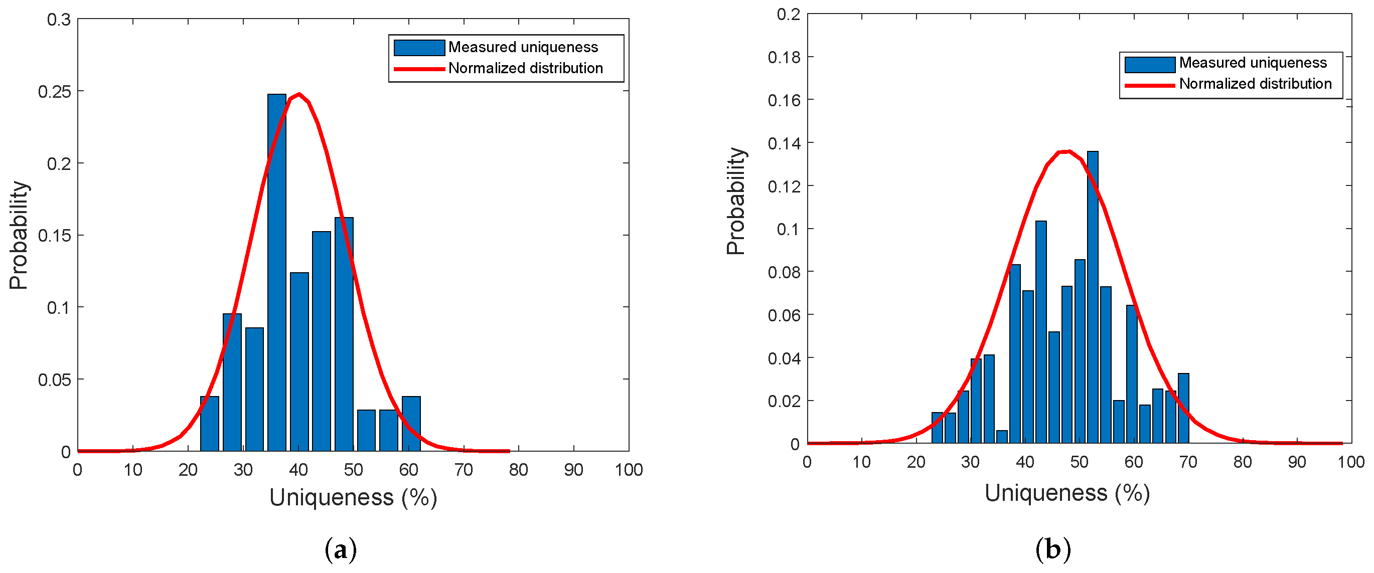
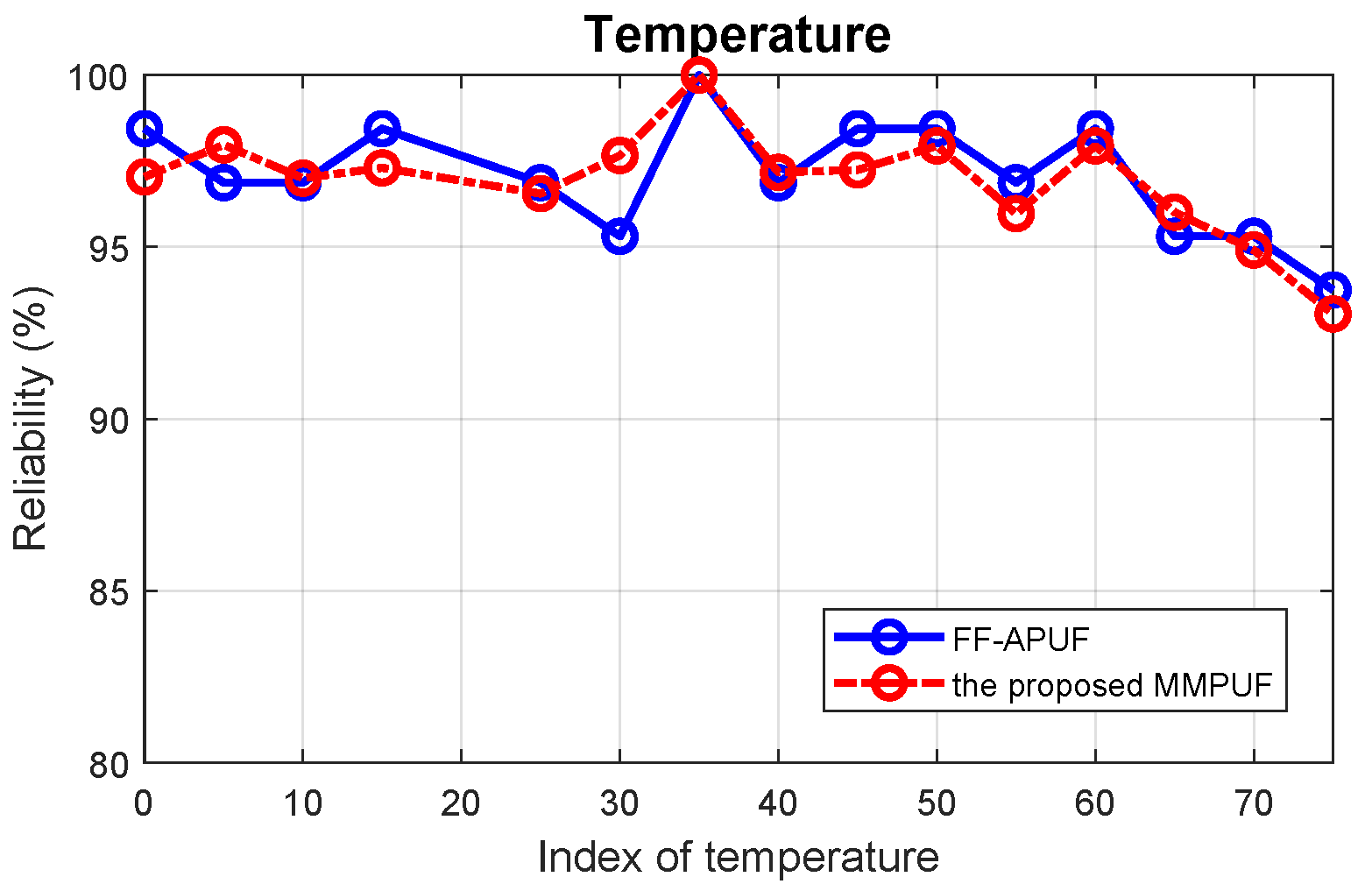
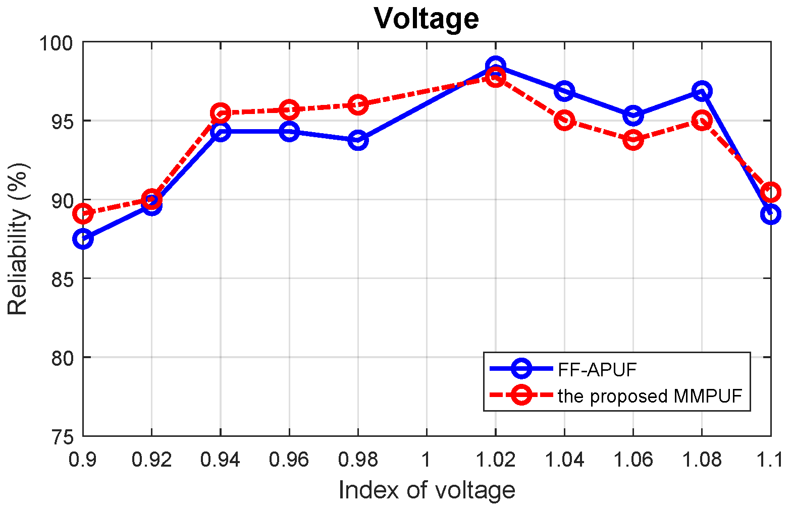
  • An experimental evaluation of this design shows the uniqueness result of 40.60%, which is much better compared with the previous Multi-PUF designs. Moreover, the proposed MMPUF design achieves good reliability results over temperature and voltage of 96% and 94%, respectively.
The rest of this paper is organized as follows. Section 2 reviews the related work of modeling attack-resistant PUF designs. We present the mathematical models of both the Multi-PUF and XMPUF in Section 3. In Section 4 we present the proposed MMPUF design and compare it with the XMPUF design. The modeling attack results of the proposed MMPUF design are discussed in Section 5 and the hardware evaluation is presented in Section 6. We conclude with a summary and discussion of our results and future work in Section 7.

2. Related Work

2.1. Modeling Attack-Resistant PUF Designs

One of the most widely known approaches for the improvement of the resistance of an APUF design to ML attacks is to increase its non-linearity. Typical techniques include XOR gate-based APUF [7] and lightweight APUF [8]. Non-linear APUFs based on Voltage Transfer Characteristics (VTC) [11] and current mirrors [19] have been proposed specifically to thwart such modeling attacks. Software and protocols-based solutions [20,21] have also relatively improved the resistance to ML attack. However, most of these designs have been proven to be vulnerable to advanced and well controlled ML attacks [22].
rMPUF and cMPUF in [23], based on an MPUF design, are among the recent improvements to enhance the reliability. Figure 1a shows the conventional MPUF and Figure 1b illustrates the cMPUF. In Figure 1, A i d represents the i-th Arbiter PUF connected to the MUX data input. A i S represents the i-th arbiter PUF connected to the MUX selection input. R i d and R i s represent the response connected to the data input and the selection input, respectively. Though MPUFs in [23] have significantly improve the resistant to ML attack, the hardware cost overhead also increased a lot. Moreover, the uniqueness and reliability was based on the simulation and no FPGA implementation was provided.

2.2. Weak PUF Based Multi-PUF Design

The concept of combining both Weak and Strong PUFs in a PUF design, named Multi-PUF, to improve the quality of the overall response has already been studied [24,25,26]. In Reference [25], the authors proposed a composite PUF by using smaller PUFs as design building blocks to build a larger challenge-space PUF, as shown in Figure 2. However, it exhibits poor uniqueness results for both RO PUF and APUF-based composite designs implemented on an FPGA, achieving a uniqueness of less than 10% for the APUF (the ideal value for uniqueness is 50%).
Obviously, the reliability of the Weak PUF is critical to the performance of the overall Multi-PUF design. Some types of Weak PUF designs have demonstrated high reliability with/without post-processing techniques, e.g., DRAM PUF [27], FPGA-based PUF ID generator [28], etc. The lightweight and reliable PUF ID generator design [28], which was referred to as PicoPUF, was used to show the feasibility of the Multi-PUF design. In Reference [28], it has been presented that the PicoPUF design can achieve almost 100% reliability through a lightweight post-processing. Generally, any type of Strong PUF can be used to construct the Multi-PUF design, e.g., APUF [5] or FF-APUF [29]. In this scheme, the challenge to a Strong PUF is completely obfuscated by Weak PUFs. As an example, the previously proposed XMPUF design [18], shown in Figure 3, is composed of n PicoPUF designs and an n-stage APUF design. The response of the i t h PicoPUF is XORed with the challenge bit c i to mask the original challenge bit and a new challenge bit c i is generated. c 1 , c 2 , , c n is the challenge input into the Multi-PUF and c 1 , c 2 , , c n is the challenge generated from the PicoPUFs, which are used as the challenges for the APUF.

3. Mathematical Analysis of the Conventional Multi-PUF and XMPUF Designs

The conventional Multi-PUF design is shown in Figure 3, which is composed of two parts, Weak PUFs and a Strong PUF. The output of the Weak PUFs will be combined with original challenge bits to produce new challenges. The Weak PUFs can be considered to be a pre-processing circuit which is used to mask the original challenges. Then, the new challenges are sent to the Strong PUF. In most conventional Multi-PUF designs, the Strong PUF is based on an APUF, whose mathematical model can be separated into two parts, the pre-processing circuit and APUF models.

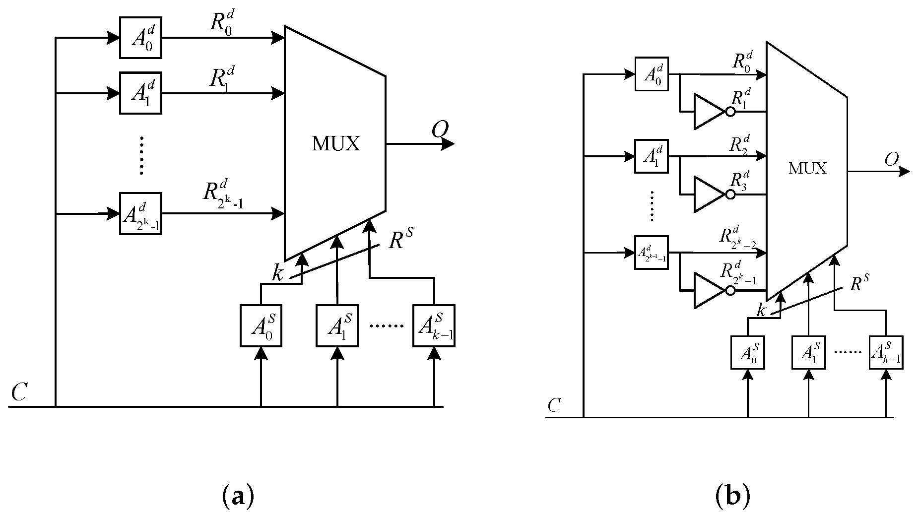
3.1. Mathematical Model of Conventional Multi-PUF Design

The mathematical model of the APUF in the previously proposed XMPUF design can be represented as Equation (1). The challenge vector C = ( c 1 , c 2 , , c n ) is generated from n Weak PUF designs, where c i is the output of the i t h Weak PUF.
Δ = W · Φ ( C ) T
and Φ ( C ) = ( φ 1 ( c ) , φ 2 ( c ) , , φ k ( c ) , 1 ) is a feature vector,
φ i ( c ) = j = i k ( 1 2 c j )
The new challenge bit c i can be represented as:
c i = f ( c i , x i )
Hence, Equation (2) can be transformed into Equation (4).
φ i ( c ) = j = i k ( 1 f ( c j , x j ) )
Equation (4) indicates that φ i ( c ) is a function of both the original challenge bit c i and output of ith Weak PUF x i .
Equation (4) can be considered into two cases depending on φ i ( c ) . The first case is when φ i ( c ) is as follows:
φ i ( c ) = u ( c i , c i + 1 , , c n ) · v ( x i , x i + 1 , , x n )
where u ( · ) is a function of the original challenge C, and v ( · ) is a function of the output of Weak PUF.
In this condition, Equation (1) can be transformed as
Δ = W · Φ ( C ) T = ω 1 , ω 2 , , ω k , ω k + 1 · φ 1 ( c ) , φ 2 ( c ) , , φ k ( c ) , 1 T = ω k + 1 + i = 1 k ω i · v ( x i , x i + 1 , , x n ) · u ( c i , c i + 1 , , c n ) = θ k + 1 + i = 1 k θ i · u ( c i , c i + 1 , , c n ) = ( θ 1 , θ 2 , , θ k , θ k + 1 ) · u 1 ( c ) , u 2 ( c ) , , u k ( c ) , 1 T = Θ · U ( C ) T
where θ i = ω i · v ( x i , x i + 1 , , x n ) , for i = 1 , 2 , , k ; and θ k + 1 = ω k + 1 . Equation (6) presents that the delay difference can be represented by the product of two items, Θ and U ( C ) T . Θ are the parameters of APUF and Weak PUF, which can be revealed by machine learning algorithms. U ( C ) T includes the information from the original challenge, C. Θ · U ( C ) T = 0 determines a separating hyperplane. Hence, the process of attacking this is the same as that of the conventional APUF as shown in [6,9,30].
The second case is that φ i ( c ) is a function of both the original challenge C and outputs of Weak PUF. Due to this, the φ i ( c ) can be written as follows:
φ i ( c ) = g ( c i , c i + 1 , , c n ; x i , x i + 1 , , x n )
In this condition, Equation (6) can be expressed as
Δ = W · Φ ( C ) T = ω 1 , ω 2 , , ω k , ω k + 1 · φ 1 ( c ) , φ 2 ( c ) , , φ k ( c ) , 1 T = ω k + 1 + i = 1 k ω i · g ( c i , c i + 1 , , c n ; x i , x i + 1 , , x n )
Equation (8) shows a non-linear classification, which makes linear classifier invalid, e.g., LR.

3.2. Mathematical Model of the Previous XMPUF Design

The XMPUF design, an example of the Multi-PUF design, is composed of n PicoPUF designs and a n-stage APUF design. The mathematical model for the output of the XMPUF design is the same as the Multi-PUF design as Equations (1) and (3). For the XMPUF design, XOR operation is used as an obfuscation function, f ( · ) , to generate a challenge c 1 , c 2 , , c n from an original challenge c 1 , c 2 , , c n . At the i t h stage, the challenge c i is defined as Equation (9).
c i = c i x i
where c i is the ith bit of the original challenge and x i is the ith output bit of the PicoPUF. c i x i in Equation (9) can be transformed to Equation (10).
c i x i = c i + x i 2 c i · x i
Hence, the output of the XMPUF design in Equation (1) can be represented as
φ i ( c ) = j = i k ( 1 2 c j ) = j = i k 1 2 ( c j + x j 2 c j · x j ) = j = i k ( 1 2 c j ) ( 1 2 x j ) = j = i k ( 1 2 c j ) · j = i k ( 1 2 x j )
Equation (11) can be simplified as the product of two continuous product items. j = i k ( 1 2 x j ) only contains the output of the ith PicoPUF x i , which means it is independent of the original challenge. A new variable a i is defined as
a i = j = i k ( 1 2 x j )
Then Equation (11) can be rewritten as follows:
φ i ( c ) = a i j = i k ( 1 2 c j )
Hence, the delay model of the XMPUF can be derived as follows:
Δ = W · Φ ( C ) T = ω 1 , ω 2 , , ω k , ω k + 1 · φ 1 ( c ) , φ 2 ( c ) , , φ k ( c ) , 1 T = ω k + 1 + i = 1 k ω i · φ i ( c ) = ω k + 1 + i = 1 k ω i · a i ( j = i k ( 1 2 c i ) ) = θ k + 1 + i = 1 k θ i · φ ( c i ) = Θ · Φ ( C ) T
where θ i = ω i a i , for i = 1 , 2 , , k and θ k + 1 = ω k + 1 . Due to a separate hyperplane Θ · Φ ( C ) T = 0 , the parameters vector of the output of the XMPUF design can be calculated by the LR modeling attack, which will be discussed later.

4. The Proposed MMPUF Design
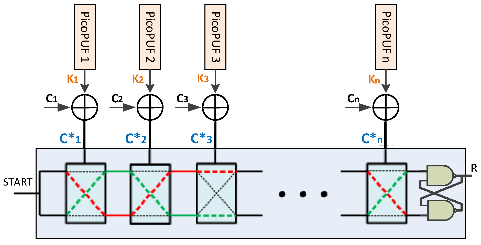
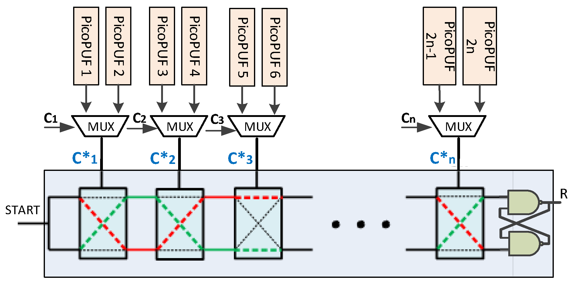
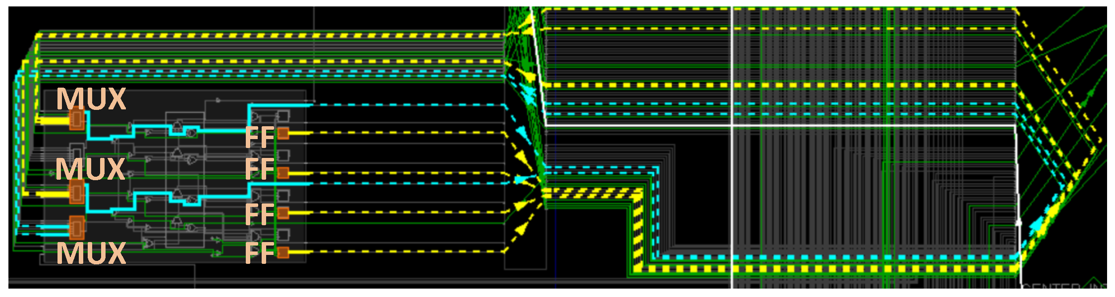
4.1. Circuit Design

The proposed MMPUF design, shown in Figure 4, is proposed to prevent the modeling attacks. Instead of using XOR gates, MUX is used as the function f ( · ) of the previously proposed XMPUF design to obfuscate the challenge. At each stage, a MUX selects one of two responses from two PicoPUFs by 1-bit of the original challenge and outputs the response as a 1-bit new challenge.
The difference between XMPUF and MMPUF designs is the pre-processing circuit, i.e., the function f ( · ) . Note, it has the probability to generate the same response from two different PicoPUFs for some stages, e.g., both are 0 s or 1 s. Hence, the PicoPUFs with different responses are selected to avoid this problem.

4.2. Mathematical Analysis

The new challenge, c 1 , c 2 , , c n generated from the PicoPUF circuits, is composed of the original challenge, a MUX and two PicoPUFs. The output of the delay model for the proposed MMPUF design can be described the same as Equations (1) and (3). Compared to the XMPUF design, the only difference is the operation of the function f ( . ) . For the XMPUF design, an XOR is used. For the proposed MMPUF design, a MUX is used and can be described as follows:
c i = c i · x i + ( 1 c i ) · y i
where x i , y i {0,1} are the outputs of two PicoPUFs and c i {0,1} is the ith bit of the original challenge.
According to Equation (3), the parameter φ i ( c ) of the proposed MMPUF design can be expressed as follows:
φ i ( c ) = j = i k ( 1 2 c j ) = j = i k 1 2 c j · x j + ( 1 c j ) · y j = j = i k 1 2 y j + 2 c j · ( y j x j )
Compared to Equation (11), Equation (15) is different in the form of Equation (5). There is no separate hyperplane to form the decision boundary, as it is difficult to find a function f ( · ) to map k-dimension vector ( c 1 , c 2 , , c k ) into a linear space. Therefore, the machine learning methods, e.g., LR, are difficult to model such non-linear architecture.
When the outputs of two PicoPUFs are the same, i.e., y j = x j , both outputs are 0 s or 1 s. Hence, Equation (15), can be represented as Equation (16):
φ i ( c ) = j = i k 1 2 y j = j = i k 1 2 x j
It shows that φ i ( c ) only depends on the output of PicoPUFs.
While the output is different, the relation between x i and y i can be expressed as y i = 1 x i . As a result, Equation (15) can be simplified as:
φ i ( c ) = j = i k ( 1 2 c j ) · j = i k ( 1 2 x j )
These two different circumstances can lead to different simulation modes. However, only the Secure Data Base (DB) at the register process will know the results of the PicoPUFs and this will partly obfuscate the relationship between challenges and responses for an adversary to collect sufficient valid CRPs.
Therefore, this will not affect the resistance of the proposed MMPUF to ML attacks since both the combinations (the same or different outputs of two PicoPUFs) will contribute to the final results. As can be seen from the results in Section 5, the proposed MMPUF decreases the successful prediction rates of CMA-ES attacks around 20% compared with XMPUF due to the obfuscation effects.

5. Machine Learning Attack Results

Machine learning-based modeling attacks, used to build theoretical models for target circuits, have been commonly employed to model the behavior of delay-based Physical unclonable function (PUF) designs on FPGAs and ASICs [6,8,9,10]. The basic idea is to use the known CRPs to train the proposed model and predict the unknown response of a given challenge. Hence, to fairly compare with other works, we build and analyze the proposed MMPUF design through a theoretical model to comprehensively evaluate the modeling attack resistance of the proposed MMPUF design in different conditions, e.g., noise. The hardware implementation is used to verify PUF metrics (e.g., uniqueness and reliability, etc.) and prove the practicability and feasibility of the proposed MMPUF design on FPGA.

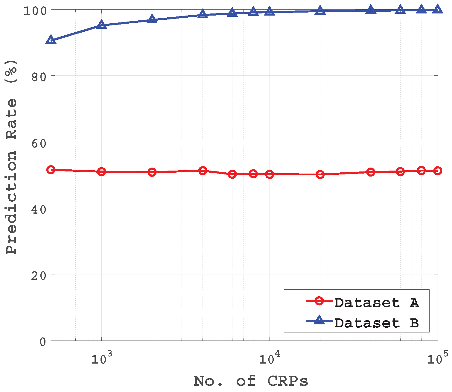
5.1. LR Attack Results

In this work, we use an open source implementation of LR with RProp programmed by Ulrich et al. [6] in Python, which are available from [31].

5.1.1. Results for the XMPUF Design Using Different Feature Vectors

As discussed in Section 3.2, the delay difference Δ of the XMPUF design can be expressed as Θ · Φ ( C ) T . It is necessary to transform the challenge vector C = ( c 1 , c 2 , , c k ) to feature vector Φ ( C ) = ( φ 1 ( c ) , φ 2 ( c ) , , φ k ( c ) , 1 ) to build up an accurate delay model since there is no linear relationship between challenge vector C = ( c 1 , c 2 , , c k ) and delay difference Δ . Figure 5 presents the LR modeling results on the XMPUF design using two feature vectors, C and Φ ( C ) , respectively. Dataset A is the result which uses feature vector Φ ( C ) , while Dataset B is the result which uses feature vector C. It has been shown that the LR achieves almost 100% attacking accuracy by applying the feature vector Φ ( C ) . In a contrast, it is difficult for the LR to train and figure out an accurate model by directly applying the feature vector C.

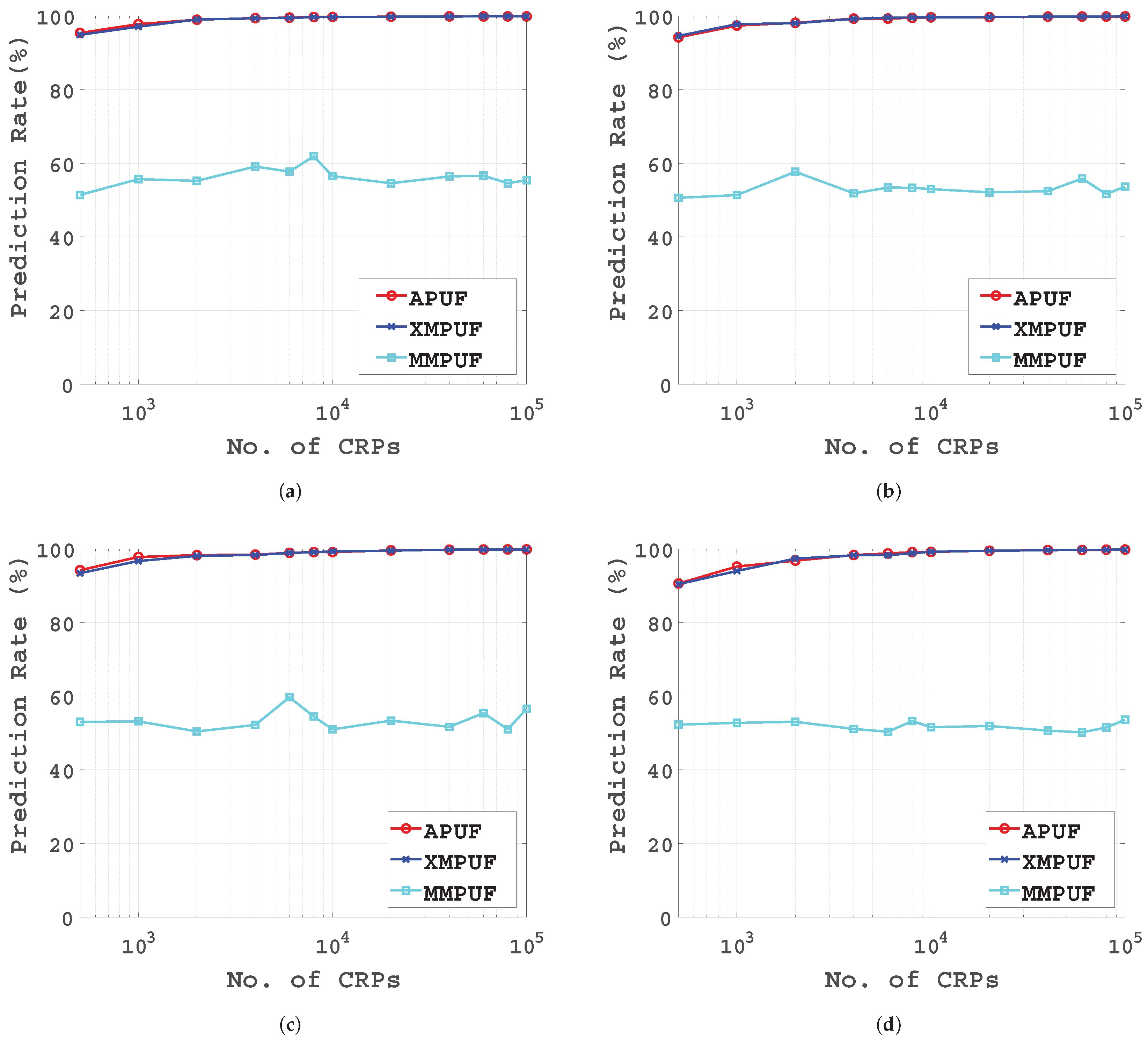
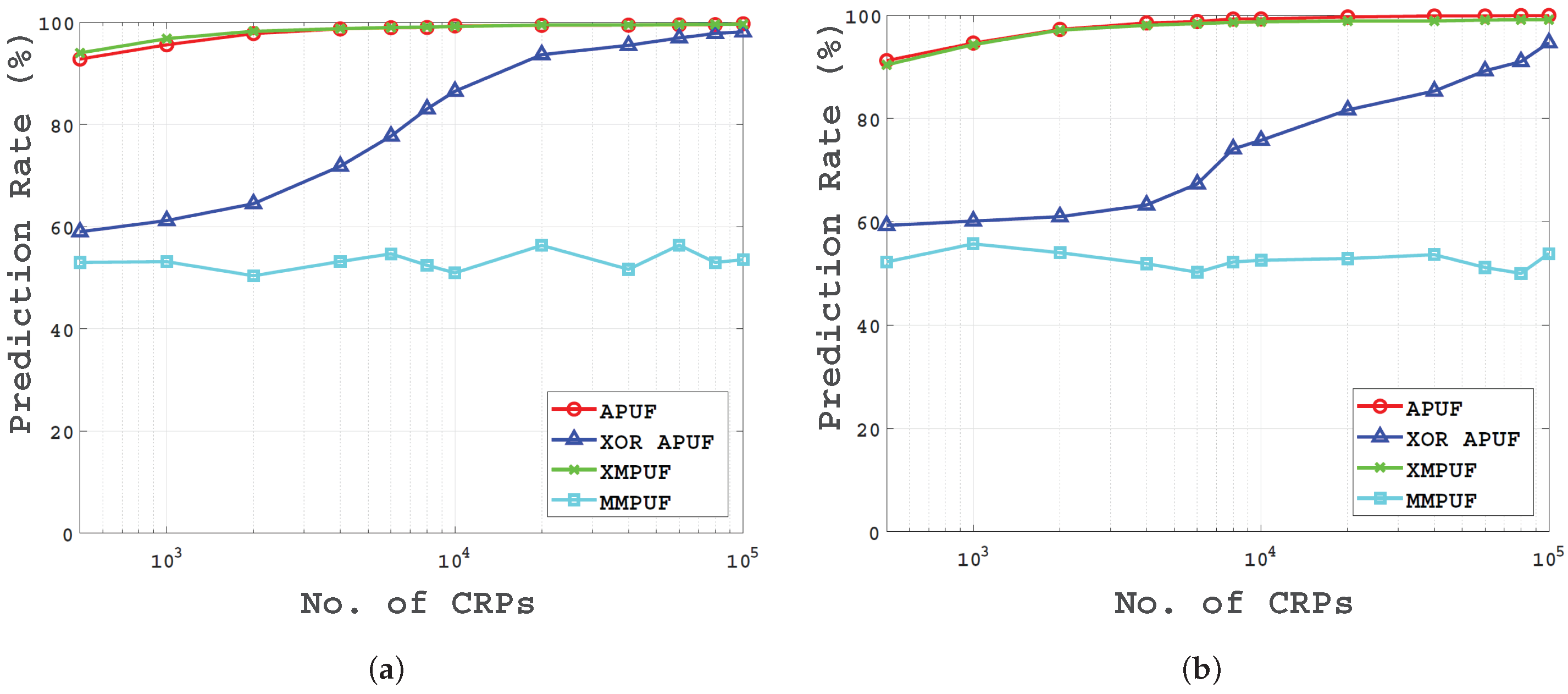
5.1.2. The Prediction Rates of The XMPUF and MMPUF Designs

To predict the Multi-PUF designs using LR, a group of tests with different numbers of training samples is carried out. In Figure 6, the prediction rates for the conventional APUF, the previously proposed XMPUF and the proposed MMPUF designs are presented in different numbers of training samples from 500 to 100,000, as well as different numbers of stages from 16 to 128.
In Figure 6, it can be seen that both the conventional APUF and XMPUF designs are successfully predicted. However, for the MMPUF design, the prediction rate is far less than the former two, which means the proposed MMPUF design demonstrates good resistance to the attacks using LR.
Figure 7 gives the prediction rate of three PUF designs with training sample sets size of 100,000. It can be seen that with a large sample size, the conventional Arbiter PUF and the XMPUF design can be successfully predicted with high reliability with stages from 16 to 256, while the prediction rate of the MMPUF design is less than 59%. The prediction rate of the MMPUF design is significantly decreased with the number of stages increased and is stable in a small range.

5.1.3. Results on Both the MMPUF and XMPUF Designs Affected by Noise

In a practical circuit, there exists various environmental variations, such as temperature or voltage, to affect the output of a PUF. We assume the noise is a variable which obeys the Gaussian distribution of norm (0, σ n ). In Reference [10], Becker et al. presented an equation to describe the delay difference affected by environmental noise:
Δ D = Δ D P U F + D n o i s e = W · Φ ( C ) T + D n o i s e
and
r = 1 , i f Δ D P U F + D n o i s e > 0 0 , i f Δ D P U F + D n o i s e < 0
They pointed out that if the Δ D P U F is greater than the D n o i s e , the noise term is unlikely to change the sign of Δ D , and if the delay difference Δ D P U F is close to zero, the chance that the response bit changes due to D n o i s e is much higher. Based on this fact, in this work, the same noise is added to the model, but different from [10], it is more reasonable that D n o i s e should affect every stage of the PUF, which results in Equation (20):
Δ D = ( W + D n o i s e ) · Φ ( C ) T
Theoretically, there is no difference between Equations (18) and (20); however, Equation (20) is closer to the practical situation.
Table 1 gives the prediction rates of three structures with the number of stages, 128, under the influence of noise. These noises have the same mean value but with different variance. When σ n = 0, this means the circuit is in an ideal environment without noise.
It can be seen that the prediction rates of both the conventional APUF and XMPUF decreased slightly with increasing variance of the σ n . With a larger sample size of CRPs, the prediction rate is still very low as shown in Figure 8.
There are some differences between our experiments and Ulrich’s. In Ulrich’s experiment, errors were inserted to CRPs directly. In our experiment, we add the noise to the delay element at each PUF stage.
For the MMPUF design, the prediction rate is not affected by the noise as the prediction accuracy is around 50%. It is clear that if the prediction of an algorithm is close to 50%, it means that this algorithm cannot estimate the model for the reason that the probability of random guessing is also 50%.

5.1.4. Results on the MMPUF Design with Different Numbers of MUXs

In Section 4.2, we mentioned that at some stages of MMPUF design, if the responses of two PicoPUFs are the same value, half of the original challenge bits are unused. To counter this, we can decrease the number of MUXs in the MMPUF. More specifically, some stages will receive the original challenge bits directly without MUXs and PicoPUFs. In our experiment, these stages without MUXs are chosen randomly.
Figure 9 gives the prediction rate of the MMPUF design with different numbers of MUXs. In particular, the top curve is the prediction rate for the conventional APUF design with a training sample size from 500 to 100,000 and the number of MUX is 0. The curve which uses 128 MUXs is the prediction rate for the MMPUF design.
It can be seen that the prediction rate of the MMPUF design decreases rapidly with an increasing number of the MUXs. Even the PUF design with 8 MUXs, the prediction rate is only around 70%, and with the number of MUXs beyond 32, the prediction rate is around 50%. The number of MUXs can be selected depending on the need for application in practice. For security concerns, the PUF design with small amount of MUXs is not recommended.

5.2. Attack Results Using SVM

To have a comprehensive analysis, support vector machines (SVM) attack is also used to evaluate the proposed MMPUF design. SVM is one of the most popular ML technique which can learn a binary classification pattern from a set of training examples [32,33].
Figure 10 shows the prediction rates for both the conventional APUF, XOR APUF, XMPUF and MMPUF designs with training sample sets size from 1000 to 100,000, and assuming both 64-bit and 128-bit challenges. It can be seen that the conventional APUF, XMPUF design can be successfully predicted for both 64-bit and 128-bit designs. For the XOR APUF, it is resistant to SVM attack while the training CRPs is less than 10 4 . However, it can be accurately predicted when the training sets reach to 10 4 . For the MMPUF design, the prediction rate remains below 53.67% for a 64-bit MMPUF and 52.44% for a 128-bit MMPUF. Therefore, it is clear that the proposed MMPUF design is more difficult to be attacked compared with several conventional APUF, XOR APUF and XMPUF design.
The final prediction rates and training time for the APUF, XOR APUF, XMPUF and MMPUF are illustrated in Table 2. It can be seen from the table that the APUF and XMPUF are vulnerable to SVM attack. Although the XOR APUF can be broken by the SVM attack, it needs more training CRPs and training time, up to 3 h and 30 min. The training time for the 128-bit MMPUF of 10,000 CRPs is about 23.54 s and the prediction rate always remains under 52.44%, which means the proposed MMPUF presents a good resistance to SVM attack.

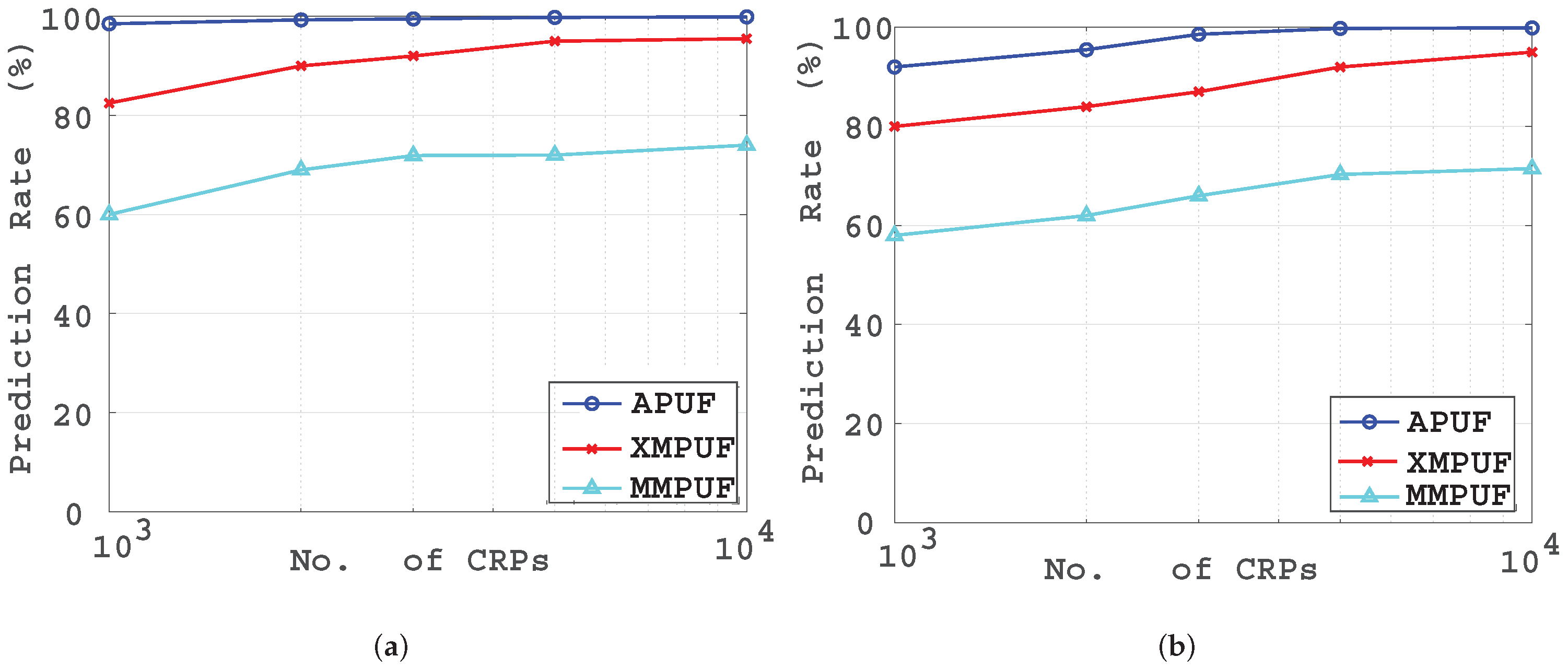
5.3. Attack Results Using CMA-ES

For the reliability-based CMA-ES algorithm, we follow the work by Becker [10] and the source code in MATLAB is adopted from [34]. A Gaussian distribution is employed to generate and simulate a group of random numbers for the delay elements in the PicoPUF and the conventional Arbiter PUF. To model the impact of noise, a variable is added to the delay difference of each APUF model with Gaussian distribution of norm ( 0 , σ n ) .
Figure 11 shows the prediction rates for both the conventional APUF and the two Multi-PUF designs with training sample sets size from 1000 to 10,000, and assuming both 64-bit and 128-bit challenges. It can be seen that the conventional APUF and XMPUF design can be successfully predicted for both 64-bit and 128-bit designs. However, compared with the conventional APUF, the prediction accuracy of XMPUF design is lower for the reason that XMPUF design has higher complexity. For the MMPUF design, even with 10,000 CRPs, the prediction rate is less than 75% for a 64-bit challenge. Therefore, it is clear that the proposed MMPUF design is more difficult to be attacked compared with the conventional APUF and XMPUF design. Similarly, for the MMPUF design, even with 10,000 CRPs, the prediction rate is still less than 71% for a 128-bit challenge. These results indicate that the required number of training samples grows by increasing the number of delay stages, i.e., the bit length of the challenge.
The proposed MMPUF has better resistant to the CMA-ES attack than the conventional APUF and XMPUF. It requires more efforts, an exponential number of CRPs, for modeling attacks. When the number of training sets is increased to 42,000 for 64-bit MMPUF and 48,000 for 128-bit MMPUF, the prediction rates can reach to 90%. As mentioned in the introduction section, the proposed MMPUF can be deployed with the fault-tolerant protocol [17] to restrict the number of accessed CRPs.

5.4. Comparison

To demonstrate the security of the MMPUF design, Table 3 shows the prediction rates of different types of PUF designs. For both 32-bit length and 64-bit length PolyPUF design [35], the prediction rates are around 50%, while the attack model is Artificial Neural Network (ANN). The proposed MMPUF design can achieve a prediction rate of 50% using LR. Hence, both the PolyPUF and MMPUF designs exhibit good resistance to machine learning attacks. For the OB-PUF design [12], the prediction rate can be up to 70% with a large sample size of CRPs by applying LR. The randomization level of RPUF design [13] in Table 3 is 2, and with 200 CRPs, the prediction rate is up to 69%, while the attack method is Compound Heuristic Algorithm [36]. Compound Heuristic Algorithm is an improving algorithm based on ES. To compare with this, we give the results of the MMPUF which is attacked by CMA-ES. In Table 3, the prediction rate of the MMPUF is 60.51% for a 64-bit length PUF design and 58.61% for a 128-bit PUF design. The attack result of the MMPUF is close to that of RPUF, but MMPUF need to consume more CRPs, which means it is more resistant to ML attack. Those results indicate that the proposed MMPUF design demonstrates a significantly higher attack resistance than most of the existing designs.

6. Hardware Implementation and Performance Evaluation

As the proposed MMPUF design exhibits good resistance to LR machine learning attacks, it is also expected to achieve good PUF metrics. In this work, the key metrics of uniqueness and reliability are evaluated. The proposed MMPUF design is implemented on Digilent Nexys 4 boards that comprise Xilinx Artix-7 FPGA. The proposed MMPUF design has been implemented on each of 11 Artix-7 FPGAs producing a total of 22 individual implementations for testing.
To present a comprehensive evaluation result and prove the practicability of the proposed MMPUF design, we have also implemented and evaluated the design on five Xilinx Kintex-7 boards. Each board implements two identical PUF instances. Hence, ten MMPUF instances in total are implemented on Kintex-7 KC705 boards. Both Artix-7 and Kintex-7 are built using the same foundry process—TSMC 28 nm. The design of the fabric for the Artix-7 is tailored for lower cost, whereas the Kintex-7 are tuned for higher performance. Typically, there is about a 15% speed penalty in using Artix-7 over Kintex-7.

6.1. Hardware Implementation

Strong PUFs, such as APUF, suffer from several quality issues in FPGA implementation. It is difficult to achieve a high uniqueness and reliability which can limit their authentication performance in practice. To demonstrate the proposed MMPUF design, it is important to choose an FPGA-based APUF design that has a high uniqueness and reliability. The lightweight FF-APUF design [29] is adopted. It has a higher uniqueness (∼40%) compared to the conventional APUF (∼9%) on Xilinx 7 series FPGA implementation. Moreover, a 64-stage FF-APUF achieves good reliabilities of 97.10 % and 93.90 % over a temperature range of 0 °C∼70 °C and ± 10 % voltage variations, respectively. Hence, the FF-APUF is used in the proposed XMPUF design.
To achieve a higher uniqueness result, a balanced placement and routing of the PUF design is essential. Figure 12 shows the place and route for one stage of the FF-APUF design used in the proposed MMPUF design. The routing of each delay path is balanced by a fixed routing setting in Vivado to contribute equivalent delay time as other routing. The “FF” and “MUX” in Figure 12 represent the hardware components of FF and MUX on Xilinx 7 Series FPGA used in the FF-APUF design.
Figure 13 shows the place and route of 1-bit PicoPUF design on Xilinx 7 Series FPGA. Note, two additional buffers are employed to extend the delay paths. The “FF”, “BUF” and “MUX” represent the hardware components of FF, buffer and MUX on Xilinx 7 Series FPGA used in the PicoPUF design. The routing of delay paths are balanced by a fixed routing setting in Vivado to achieve two “identical” delay paths.
Table 4 shows the hardware implementation consumption of the proposed MMPUF compared with other lightweight PUF designs. For a fair comparison, only the security related components are considered. All the PUF designs shown in Table 4 present a lightweight implementation without requiring error-correction or cryptographic hash function. Moreover, the proposed MMPUF and the PolyPUF designs are more lightweight than the others.

6.2. Uniqueness Results

Uniqueness measures inter-chip variation by evaluating how well a particular PUF circuit design can be differentiated between k different devices. Ideally, a PUF circuit is expected to produce an average inter-chip HD of 50% by comparing the response from two devices supplied with the same challenge. The uniqueness, representing the average inter-chip HD, is defined as:
Uniqueness = 2 k ( k 1 ) i = 1 k 1 j = i + 1 k HD ( R i , R j ) n · 100
where R i and R j represent N-bit responses from two PUF circuits Φ i and Φ j supplied with the same challenge C.
Figure 14 shows a histogram of the uniqueness results for the proposed MMPUF design. The uniqueness of the proposed MMPUF design achieves an empirical mean of 40.10 % on Artix-7 FPGAs and 47.30 % on Kintex-7 FPGAs. The uniqueness on Artix-7 FPGA is equivalent to the uniqueness value of the FF-APUF design [29] while the result on Kintex-7 FPGA is better. The reason may be that the Kintex-7 FPGA has higher performance and speed compared with Artxi-7 and this could increase the uniqueness of the proposed MMPUF. Moreover, compared to the uniqueness results from 5.44% to 10.82% achieved by the work [25] on Multi-PUF, the proposed MMPUF design demonstrates a higher capability to differentiate between different devices.

6.3. Reliability Results

Ideally, a given PUF circuitry, implemented on any device should be able to perfectly reproduce its output whenever it is queried with a challenge. However, environmental changes, such as temperature and power supply voltage variations, as well as the natural properties of metastability in PUF circuits induce noise in the responses. Therefore, reliability is used to quantify a PUF’s ability to reproduce a response. For a device i, reliability is established as a single value by finding the average intra-chip HD of s response samples, R i , taken at different operating conditions compared to a baseline N-bit reference response, R i , taken at nominal operating conditions. The average intra-chip HD is estimated as follows:
H D I N T R A = 1 s t = 1 s H D ( R i , R i , t ) N · 100
where R ( i , t ) is the t-th sample of R i . The percentage figure of merit for reliability can be defined as:
R e l i a b i l i t y = 100 H D I N T R A
Obviously, the ideal value for reliability is 100%.
The temperature is in a range of 0 °C∼70 °C using a convection heat chamber while the core supply voltage was varied by ± 10 % volts using a DC regulated power supply. A previously proposed post-characterization methodology [28] is adopted to improve the reliability of the PicoPUF, which has been presented to achieve almost 100 % reliability. Figure 15 and Figure 16 show the reliability results of both the FF-APUF and proposed MMPUF designs. The average reliability results of the proposed MMPUF design on Xilinx Artix-7 FPGA over temperature and voltage experiments are 96% and 94%, respectively. Due to the limitation of the evaluation board, the reliability of the proposed MMPUF design over temperature variations on Kintex-7 FPGAs are carried out and is 96.65%. By using the post-characterization for the PicoPUF design, the proposed MMPUF design achieves a similar reliability result as the FF-APUF design. Hence, the proposed MMPUF design can achieve modeling attack resistance without sacrificing reliability or uniqueness performance in practice.

7. Conclusions

In this paper, we propose a new MMPUF design which is resistant to modeling attacks by using a Weak PUF to obfuscate the challenge of a Strong PUF design. A detailed analysis of the mathematical model for the MMPUF design is presented. Three of the most widely employed machine learning-based attack techniques, LR, SVM and CMA-ES, are used to analyze the resistance of the proposed MMPUF design. Mathematical analysis and experimental results demonstrate that the proposed MMPUF is resistant to these ML attacks. To evaluate the performance and feasibility of the proposed PUF design, the MMPUF design is implemented on 22 Xilinx 7 Series FPGAs. The uniqueness metric for both the proposed MMPUF design and XMPUF design exhibit good results of 40.10% and 40.60%, respectively. The proposed MMPUF design achieves a similar reliability result as the FF-APUF design. This significantly improves upon previous work on XMPUFs and illustrates the design’s feasibility for implementation on an FPGA.

Author Contributions

Conceptualization, Y.C. and Q.M.; software, Y.F. and C.G.; validation, Y.C.; formal analysis, Y.C. and C.G.; writing—original draft preparation, Y.C., Q.M. and C.G.; writing—review and editing, W.L., C.W. and M.O.; supervision, W.L. and C.W.; project administration, W.L.; funding acquisition, W.L. and C.W. All authors have read and agreed to the published version of the manuscript.

Funding

This work is supported by the National Natural Science Foundation of China (61771239), the State Grid Corporation Science and Technology Project Funded “Key Technology Research on Trustworthy Identity Authentication of Grid Core Business” (52110418001L) and partly supported by the Engineering and Physical Sciences Research Council (EPSRC) (EP/N508664/-CSIT2).

Conflicts of Interest

The authors declare no conflict of interest.

References

  1. Pappu, R.; Recht, B.; Taylor, J.; Gershenfeld, N. Physical one-way functions. Science 2002, 297, 2026–2030. [Google Scholar] [CrossRef] [PubMed] [Green Version]
  2. Guajardo, J.; Kumar, S.S.; Schrijen, G.J.; Tuyls, P. FPGA intrinsic PUFs and their use for IP protection. In Proceedings of the International Workshop on Cryptographic Hardware and Embedded Systems, Vienna, Austria, 10–13 September 2007; pp. 63–80. [Google Scholar]
  3. Bhargava, M.; Mai, K. An efficient reliable PUF-based cryptographic key generator in 65 nm CMOS. In Proceedings of the Design, Automation & Test in Europe Conference & Exhibition (DATE), Dresden, Germany, 24–28 March 2014; pp. 1–6. [Google Scholar]
  4. Tebelmann, L.; Pehl, M.; Sigl, G. EM side-channel analysis of BCH-based error correction for PUF-based key generation. In Proceedings of the Workshop on Attacks and Solutions in Hardware Security, Dallas, TX, USA, 3 November 2017; pp. 43–52. [Google Scholar]
  5. Gassend, B.; Clarke, D.; Van Dijk, M.; Devadas, S. Silicon physical random functions. In Proceedings of the 9th ACM Conference on Computer and Communications Security, Washington, DC, USA, 18–22 November 2002; pp. 148–160. [Google Scholar]
  6. Rührmair, U.; Sehnke, F.; Sölter, J.; Dror, G.; Devadas, S.; Schmidhuber, J. Modeling attacks on physical unclonable functions. In Proceedings of the 17th ACM conference on Computer and Communications Security, Chicago, IL, USA, 4–8 October 2010; pp. 237–249. [Google Scholar]
  7. Suh, G.E.; Devadas, S. Physical unclonable functions for device authentication and secret key generation. In Proceedings of the 2007 44th ACM/IEEE Design Automation Conference, San Diego, CA, USA, 4–8 June 2007; pp. 9–14. [Google Scholar]
  8. Majzoobi, M.; Koushanfar, F.; Potkonjak, M. Lightweight secure PUFs. In Proceedings of the IEEE/ACM International Conference on Computer-Aided Design, San Jose, CA, USA, 10–13 November 2008; pp. 670–673. [Google Scholar]
  9. Rührmair, U.; Sölter, J.; Sehnke, F.; Xu, X.; Mahmoud, A.; Stoyanova, V.; Dror, G.; Schmidhuber, J.; Burleson, W.; Devadas, S. PUF modeling attacks on simulated and silicon data. IEEE Trans. Inf. Forensics Secur. 2013, 8, 1876–1891. [Google Scholar] [CrossRef] [Green Version]
  10. Becker, G.T. The gap between promise and reality: On the insecurity of XOR arbiter PUFs. In Proceedings of the International Workshop on Cryptographic Hardware and Embedded Systems, Santa Barbara, CA, USA, 19–22 August 2015; pp. 535–555. [Google Scholar]
  11. Vijayakumar, A.; Kundu, S. A novel modeling attack resistant PUF design based on non-linear voltage transfer characteristics. In Proceedings of the Design, Automation & Test in Europe Conference & Exhibition (DATE), Grenoble, France, 9–13 March 2015; pp. 653–658. [Google Scholar]
  12. Gao, Y.; Li, G.; Ma, H.; Al-Sarawi, S.F.; Kavehei, O.; Abbott, D.; Ranasinghe, D.C. Obfuscated challenge-response: A secure lightweight authentication mechanism for PUF-based pervasive devices. In Proceedings of the IEEE International Conference on Pervasive Computing and Communication Workshops (PerCom Workshops), Kollam, India, 21–22 October 2016; pp. 1–6. [Google Scholar]
  13. Ye, J.; Hu, Y.; Li, X. RPUF: Physical unclonable function with randomized challenge to resist modeling attack. In Proceedings of the IEEE Asian Hardware-Oriented Security and Trust (AsianHOST), Austin, TX, USA, 19–20 December 2016; pp. 1–6. [Google Scholar]
  14. Nguyen, P.H.; Sahoo, D.P.; Jin, C.; Mahmood, K.; Rührmair, U.; van Dijk, M. The interpose PUF: Secure PUF design against state-of-the-art machine learning attacks. IACR Trans. Cryptogr. Hardw. Embed. Syst. 2019, 243–290. [Google Scholar] [CrossRef]
  15. Yu, M.D.; M’Raïhi, D.; Verbauwhede, I.; Devadas, S. A noise bifurcation architecture for linear additive physical functions. In Proceedings of the IEEE International Symposium on Hardware-Oriented Security and Trust (HOST), Washington, DC, USA, 31 October 2014; pp. 124–129. [Google Scholar]
  16. Shi, J.; Lu, Y.; Zhang, J. Approximation Attacks on Strong PUFs. IEEE Trans. Comput. Aided Des. Integr. Circuits Syst. 2019. [Google Scholar] [CrossRef]
  17. Gu, C.; Chang, C.H.; Liu, W.; Yu, S.; Ma, Q.; O’neill, M. A Modeling Attack Resistant Deception Technique for Securing PUF based Authentication. In Proceedings of the Asian Hardware Oriented Security and Trust Symposium (AsianHOST), Xi’an, China, 16–17 December 2019; pp. 1–6. [Google Scholar] [CrossRef] [Green Version]
  18. Ma, Q.; Gu, C.; Hanley, N.; Wang, C.; Liu, W.; O’Neill, M. A machine learning attack resistant multi-PUF design on FPGA. In Proceedings of the 23rd Asia and South Pacific Design Automation Conference (ASP-DAC), Jeju, Korea, 22–25 January 2018; pp. 97–104. [Google Scholar]
  19. Kumar, R.; Burleson, W. On design of a highly secure PUF based on non-linear current mirrors. In Proceedings of the IEEE International Symposium on Hardware-Oriented Security and Trust (HOST), Washington, DC, USA, 31 October 2014; pp. 38–43. [Google Scholar]
  20. Arafin, M.T.; Gao, M.; Qu, G. VOLtA: Voltage over-scaling based lightweight authentication for IoT applications. In Proceedings of the 22nd Asia and South Pacific Design Automation Conference (ASP-DAC), Chiba, Japan, 16–19 January 2017; pp. 336–341. [Google Scholar]
  21. Zalivaka, S.S.; Ivaniuk, A.A.; Chang, C.H. FPGA implementation of modeling attack resistant arbiter PUF with enhanced reliability. In Proceedings of the 18th International Symposium on Quality Electronic Design (ISQED), Dubrovnik, Croatia, 28–30 June 2017; pp. 313–318. [Google Scholar]
  22. Su, H.; Zhang, J. Machine learning attacks on voltage over-scaling-based lightweight authentication. In Proceedings of the Asian Hardware Oriented Security and Trust Symposium (AsianHOST), Hong Kong, China, 17–18 December 2018; pp. 50–55. [Google Scholar]
  23. Sahoo, D.P.; Mukhopadhyay, D.; Chakraborty, R.S.; Nguyen, P.H. A multiplexer-based arbiter PUF composition with enhanced reliability and security. IEEE Trans. Comput. 2017, 67, 403–417. [Google Scholar] [CrossRef]
  24. Konigsmark, S.C.; Hwang, L.K.; Chen, D.; Wong, M.D. System-of-PUFs: Multilevel security for embedded systems. In Proceedings of the International Conference on Hardware/Software Codesign and System Synthesis, New Delhi, India, 12–14 October 2014; pp. 1–10. [Google Scholar]
  25. Sahoo, D.P.; Saha, S.; Mukhopadhyay, D.; Chakraborty, R.S.; Kapoor, H. Composite PUF: A new design paradigm for physically unclonable functions on FPGA. In Proceedings of the IEEE International Symposium on Hardware-Oriented Security and Trust (HOST), Washington, DC, USA, 31 October 2014; pp. 50–55. [Google Scholar]
  26. Zalivaka, S.S.; Ivaniuk, A.A.; Chang, C.H. Low-cost fortification of arbiter PUF against modeling attack. In Proceedings of the IEEE International Symposium on Circuits and Systems (ISCAS), Baltimore, MD, USA, 28–31 May 2017; pp. 1–4. [Google Scholar]
  27. Tehranipoor, F.; Karimian, N.; Yan, W.; Chandy, J.A. DRAM-based intrinsic physically unclonable functions for system-level security and authentication. IEEE Trans. Very Large Scale Integr. (VLSI) Syst. 2016, 25, 1085–1097. [Google Scholar] [CrossRef]
  28. Gu, C.; Hanley, N.; O’neill, M. Improved reliability of FPGA-based PUF identification generator design. ACM Trans. Reconfigurable Technol. Syst. (TRETS) 2017, 10, 1–23. [Google Scholar] [CrossRef] [Green Version]
  29. Gu, C.; Cui, Y.; Hanley, N.; O’Neill, M. Novel lightweight FF-APUF design for FPGA. In Proceedings of the 29th IEEE International System-on-Chip Conference (SOCC), Seattle, WA, USA, 6–9 September 2016; pp. 75–80. [Google Scholar]
  30. Lim, D.; Lee, J.W.; Gassend, B.; Suh, G.E.; Van Dijk, M.; Devadas, S. Extracting secret keys from integrated circuits. IEEE Trans. Very Large Scale Integr. (VLSI) Syst. 2005, 13, 1200–1205. [Google Scholar]
  31. Tum. Physical Cryptography Project. Technical Report. Available online: http://www.pcp.in.tum.de/code/lr.zip (accessed on 7 June 2018).
  32. Hospodar, G.; Maes, R.; Verbauwhede, I. Machine learning attacks on 65nm Arbiter PUFs: Accurate modeling poses strict bounds on usability. In Proceedings of the 2012 IEEE International Workshop on Information Forensics and Security (WIFS), Tenerife, Spain, 2–5 December 2012; pp. 37–42. [Google Scholar]
  33. Alamro, M.A.; Zhuang, Y.; Aseeri, A.O.; Alkatheiri, M.S. Examination of Double Arbiter PUFs on Security against Machine Learning Attacks. In Proceedings of the 2019 IEEE International Conference on Big Data (Big Data), Los Angeles, CA, USA, 9–12 December 2019; pp. 3165–3171. [Google Scholar]
  34. Hansen, N. The CMA evolution strategy: A comparing review. In Towards a New Evolutionary Computation; Springer: Berlin/Heidelberg, Germany, 2006; pp. 75–102. [Google Scholar]
  35. Konigsmark, S.T.C.; Chen, D.; Wong, M.D. PolyPUF: Physically secure self-divergence. IEEE Trans. Comput. Aided Des. Integr. Circuits Syst. 2015, 35, 1053–1066. [Google Scholar] [CrossRef]
  36. Ye, J.; Hu, Y.; Li, X. POSTER: Attack on non-linear physical unclonable function. In Proceedings of the ACM SIGSAC Conference on Computer and Communications Security, Vienna, Austria, 24 October 2016; pp. 1751–1753. [Google Scholar]
  37. Gu, C.; Murphy, J.; O’Neill, M. A unique and robust single slice FPGA identification generator. In Proceedings of the IEEE International Symposium on Circuits and Systems (ISCAS), Melbourne, Australia, 1–5 June 2014; pp. 1223–1226. [Google Scholar]
  38. Majzoobi, M.; Rostami, M.; Koushanfar, F.; Wallach, D.S.; Devadas, S. Slender PUF protocol: A lightweight, robust, and secure authentication by substring matching. In Proceedings of the IEEE Symposium on Security and Privacy Workshops, San Francisco, CA, USA, 24–25 May 2012; pp. 33–44. [Google Scholar]
Figure 1. The structure of (a) n , k -MPUF, (b) ( n , k ) -cMPUF.
Electronics 09 00815 g001
Figure 2. The architecture of the previously proposed XMPUF design.
Electronics 09 00815 g002
Figure 3. The XMPUF design with challenges XORed.
Electronics 09 00815 g003
Figure 4. The proposed MMPUF design with MUXs.
Electronics 09 00815 g004
Figure 5. The prediction rates of LR attack on a 64-bit XMPUF designs using different feature vectors.
Electronics 09 00815 g005
Figure 6. The prediction rates of the LR attacks for different PUF designs in various bit lengths: (a) 16 bit length, (b) 32 bit length, (c) 64 bit length, (d) 128 bit length.
Electronics 09 00815 g006
Figure 7. The prediction rates of LR attacks on 64-bit PUF designs ( σ n = 0) by using 100,000 CRPs and applying different challenge bit lengths.
Electronics 09 00815 g007
Figure 8. The prediction rates of LR attacks on 64-bit XMPUF and MMPUF designs affected by noise.
Electronics 09 00815 g008
Figure 9. LR attack results on the MMPUF design with different numbers of MUXs.
Electronics 09 00815 g009
Figure 10. The prediction rates of SVM attack on: (a) 64 bit and, (b) 128-bit MMPUF designs.
Electronics 09 00815 g010
Figure 11. The prediction rates of CMA-ES attack on: (a) 64 bit and, (b) 128-bit MMPUF designs.
Electronics 09 00815 g011
Figure 12. Place and route for one stage of 1-bit FF-APUF design [29] in the proposed MMPUF design.
Electronics 09 00815 g012
Figure 13. Place and route for 1-bit PicoPUF [37] in the proposed MMPUF design.
Electronics 09 00815 g013
Figure 14. The uniqueness results for the proposed MMPUF design (a) Artix-7 FPGAs, (b) Kintex-7 FPGAs.
Electronics 09 00815 g014
Figure 15. Reliability results considering temperature.
Electronics 09 00815 g015
Figure 16. Reliability results considering voltage.
Electronics 09 00815 g016
Table 1. Prediction Rates Affected by Noise.
TypeNo. CRPs ( × 10 3 )Gaussian Distribution of n   o r   m (0, σ n )
σ n = 0 σ n = 0.1 σ n = 0.25 σ n = 0.5
APUF190.6%88%86.2%81%
598.77%97%94.63%88.9%
2099.49%97.63%94.61%89.64%
4099.67%97.8%94.84%89.87%
8099.79%97.95%94.7%89.69%
10099.82%97.88%94.77%89.85%
XOR APUF188%87.4%86.4%84.8%
587.2%86.6%83.8%84.6%
2050.8%50.35%50.2%50.4%
4087.2%86.6%83.8%84.6%
8050.8%50.35%50.2%50.4%
10050.8%50.35%50.2%50.4%
XMPUF190.4%86.9%86.2%83.8%
598.25%95.55%94.08%88.03%
2099.51%97.46%94.61%88.58%
4099.63%97.71%94.84%88.8%
8099.77%97.89%94.9%88.59%
10099.82%97.96%94.96%88.6%
MMPUF152.24%51.57%53.9%50.36%
551.07%54.21%51.64%53.44%
2051.88%53.12%50.31%52.61%
4050.63%53.65%53.77%50.31%
8051.48%52.34%50.26%52.98%
10053.57%55.23%53.02%51.47%
Table 2. Prediction Rates and Training Time for SVM Attack.
TypePrediction Rate (Average)Prediction Rate (Maximum)No. CRPs ( × 10 3 )Training Time
APUF (64 bit)99.21%99.41%67.55 s
XOR APUF (64 bit)98.13%98.25%803:13 h
XMPUF (64 bit)99.18%99.22%67.8 s
MMPUF (64 bit)51.74%53.67%610.36 s
APUF (128 bit)99.1%99.17%1020.05 s
XOR APUF (128 bit)96.56%96.89%1003:30 h
XMPUF (128 bit)99.07%99.23%1021.65 s
MMPUF (128 bit)50.32%52.44%1023.54 s
Table 3. Comparison of Attacks between Different Types of PUF Designs.
TypeBit
Length
No. CRPs
( × 10 3 )
Prediction
Rate
Attack
Model
PolyPUF [35]325
50
500
50.1%
50.03%
50%
ANN
645
50
500
50.02%
50%
50.01%
OB-PUF [12]6410
20
100
52.28%
63.27%
71.92%
LR
RPUF [13]32
64
128
0.1
0.2
0.2
75%
59.1%
64.2%
Compound
Heuristic
Algorithm [36]
MMPUF325
50
100
52.85%
53.41%
53.66%
LR
645
50
100
53.77%
55.39%
56.55%
MMPUF32174.1%CMA-ES
641
5
10
60.51%
71.96%
74.18%
1281
5
10
58.61%
70.33%
71.55%
Table 4. Hardware Resource Comparison of the Primary Security Components.
ComponentSlender [38]NBPUF [15]PolyPUF [35]RPUF [13]Proposed MMPUF
physical unclonable function (PUF) 4 × 128 4 × 128 128128 2 × 128
LFSR1010101010
TRNG128128N/A128N/A
OthersN/A2575128N/A
Total650650213394266

