Few-Cycle Infrared Pulse Evolving in FEL Oscillators and Its Application to High-Harmonic Generation for Attosecond Ultraviolet and X-ray Pulses


National Institutes for Quantum and Radiological Science and Technology, Tokai, Ibaraki 3191106, Japan
Atoms 2021, 9(1), 15; https://0-doi-org.brum.beds.ac.uk/10.3390/atoms9010015
Submission received: 11 January 2021
/
Revised: 19 February 2021
/
Accepted: 19 February 2021
/
Published: 24 February 2021
(This article belongs to the Special Issue Collective Atomic and Free-Electron Lasing)
Abstract
:Generation of few-cycle optical pulses in free-electron laser (FEL) oscillators has been experimentally demonstrated in FEL facilities based on normal-conducting and superconducting linear accelerators. Analytical and numerical studies have revealed that the few-cycle FEL lasing can be explained in the frame of superradiance, cooperative emission from self-bunched systems. In the present paper, we review historical remarks of superradiance FEL experiments in short-pulse FEL oscillators with emphasis on the few-cycle pulse generation and discuss the application of the few-cycle FEL pulses to the scheme of FEL-HHG, utilization of infrared FEL pulses to drive high-harmonic generation (HHG) from gas and solid targets. The FEL-HHG enables one to explore ultrafast science with attosecond ultraviolet and X-ray pulses with a MHz repetition rate, which is difficult with HHG driven by solid-state lasers. A research program has been launched to develop technologies for the FEL-HHG and to conduct a proof-of-concept experiment of FEL-HHG.
1. Introduction
Bonifacio and his colleagues first suggested that free-electron laser (FEL) may be operated in the superradiant regime, in which the radiated peak power is proportional to the squared electron number, , from self-bunched systems [1]. The radiation intensities scaling as the squared emitters number is similar to superradiance at two-level systems as defined by Dicke [2]. Superradiance of a single electron bunch or a periodically bunched beam may occur in any kind of free-electron radiation emission scheme including synchrotron radiation, undulator radiation, and FEL [3]. In the superradiance FEL, a periodical bunching structure is self-organized in the electron beam traversing an undulator and the bunched beam emits cooperative radiation. Superradiance appears in both single-pass FEL amplifiers and multi-pass FEL oscillators when the FEL is operated at an appropriate condition.
The lasing behavior of FEL can be classified in terms of the characteristic lengths: , , and . The first parameter, , is the bunch length. In FELs driven by RF linear accelerators, the bunch length is typically 0.1–1 mm (0.3–3 ps). The slippage length, , is the product of the radiation wavelength, , and the number of undulator periods, . The last parameter, , the cooperation length, is a function of the radiation wavelength, , and the fundamental FEL parameter, , as , which is equal to the slippage length in an exponential gain length.
Superradiance in FEL amplifiers is classified into weak and strong superradiance according to the relationship between the characteristic lengths [4]. The weak superradiance occurs when an FEL is operated in the high-gain and strong-slippage regime, . The electron bunch is self-bunched due to the FEL interaction and the self-bunched electrons emit cooperative radiation in the slippage region. The intensity of the radiation at the slippage region scales as . Bonifacio called the radiation weak superradiance because the intensity at the slippage region is smaller than that of the steady-state high-gain FEL lasing, where the slippage is negligible. Strong superradiance appears in a long-pulse high-gain FEL amplifier, and . In this case, the trailing region of the FEL pulse exhibits a spiking behavior as a result of the emission of self-bunched electrons in the slippage region. The intensities at the slippage region are much larger than that of the steady-state FEL lasing.
Superradiance is also observed in short-pulse FEL oscillators, where a periodical bunching structure is self-organized after the recursive interaction of the electron bunches and the optical pulse to emit cooperative radiation in the slippage region. In the present paper, we review historical remarks of superradiance FEL experiments in short-pulse FEL oscillators with emphasis on few-cycle pulse generation and discuss the application of few-cycle FEL pulses to attosecond ultraviolet and X-ray pulses via high-harmonic generation from gas and solid targets.
Superradiance in short-pulse FEL oscillators exhibits unique features: (i) high extraction efficiency; (ii) isolated (or solitary) few-cycle pulse; (iii) the lasing maintained by shot noise; and (iv) possible carrier-envelope phase stabilization by an external seed laser. In the following sections, we see experimental results of superradiance in FEL oscillators and outline the above unique features. Then, we discuss possible applications of such few-cycle pulses to high-harmonic generation for attosecond ultraviolet and X-ray pulses, that is FEL-HHG. Finally, the research program established for developing basic technologies and conducting a proof-of-principle experiment for the FEL-HHG is presented.
2. Superradiance in Short-Pulse FEL Oscillators
Superradiance in short-pulse FEL oscillators has been studied experimentally and theoretically. In this section, we review experimental results of superradiance in short-pulse FEL oscillators at FELIX, JAERI, and Kyoto University.
2.1. Experiments at FELIX
FELIX is an FEL facility based on a 45-MeV S-band normal conducting linac [5]. In the FEL oscillator at FELIX, intense pulses of six optical cycles were observed [6]. The ultra-short pulses were generated when the FEL oscillator was operated at a small negative detuning of the cavity length. This lasing behavior was analytically studied in the context of supermode theory and recognized as a multi-supermode regime that occurs in the limit where all the supermodes converge toward a unique degenerate supermode [7,8].
The lasing at FELIX was further examined by measuring the pulse energy and bandwidth of the FEL radiation with varying the bunch charge. It was found that the FEL extraction efficiency, , and the FEL pulse energy, , scaled with the bunch charge, q, as and . The spectral width was also broadened as increasing the bunch charge, , which implied the duration of the optical pulse, , scales as [9]. From these observations, they concluded that the lasing was similar to superradiance in high-gain FEL amplifiers.
The superradiance scaling law, , conduced to the few-cycle optical pulse generation at FELIX with a high-gain operation regime. The few-cycle pulse is, however, only available at the transient regime before the saturation in the macropulse. After the onset of saturation, the lasing shifts to a chaotic regime and an isolated few-cycle pulse is no longer available [7].
2.2. Experiments at JAERI-FEL
An infrared FEL oscillator driven by a superconducting linac was developed at Japan Atomic Energy Research Institute (JAERI). Superradiance FEL was also demonstrated in the FEL oscillator at JAERI. The difference from the FELIX experiment was a long macropulse, up to 1 ms, generated by the superconducting linac. A new finding from the experiment at the JAERI-FEL was the lasing at the cavity-length detuning equal to zero (or the perfectly synchronized optical cavity length) appearing in the high-gain regime.
Figure 1 shows FEL efficiency as a function of the cavity length detuning measured at the JAERI-FEL. In the experiment, the FEL efficiency was evaluated from the energy spectrum of the spent electron beam. The absolute detuning length was measured by the laser pulse stacking in the FEL cavity with a mode-locked Ti:sapphire laser synchronized to the eighth harmonic of the electron bunch repetition rate. Since the intensity of the stacked pulse becomes maximum when the cavity length detuning is zero, the absolute cavity length can be determined from the stacked signal. From the detuning curve, we can confirm that the high-efficiency FEL lasing occurred at , the perfectly synchronized optical cavity length.
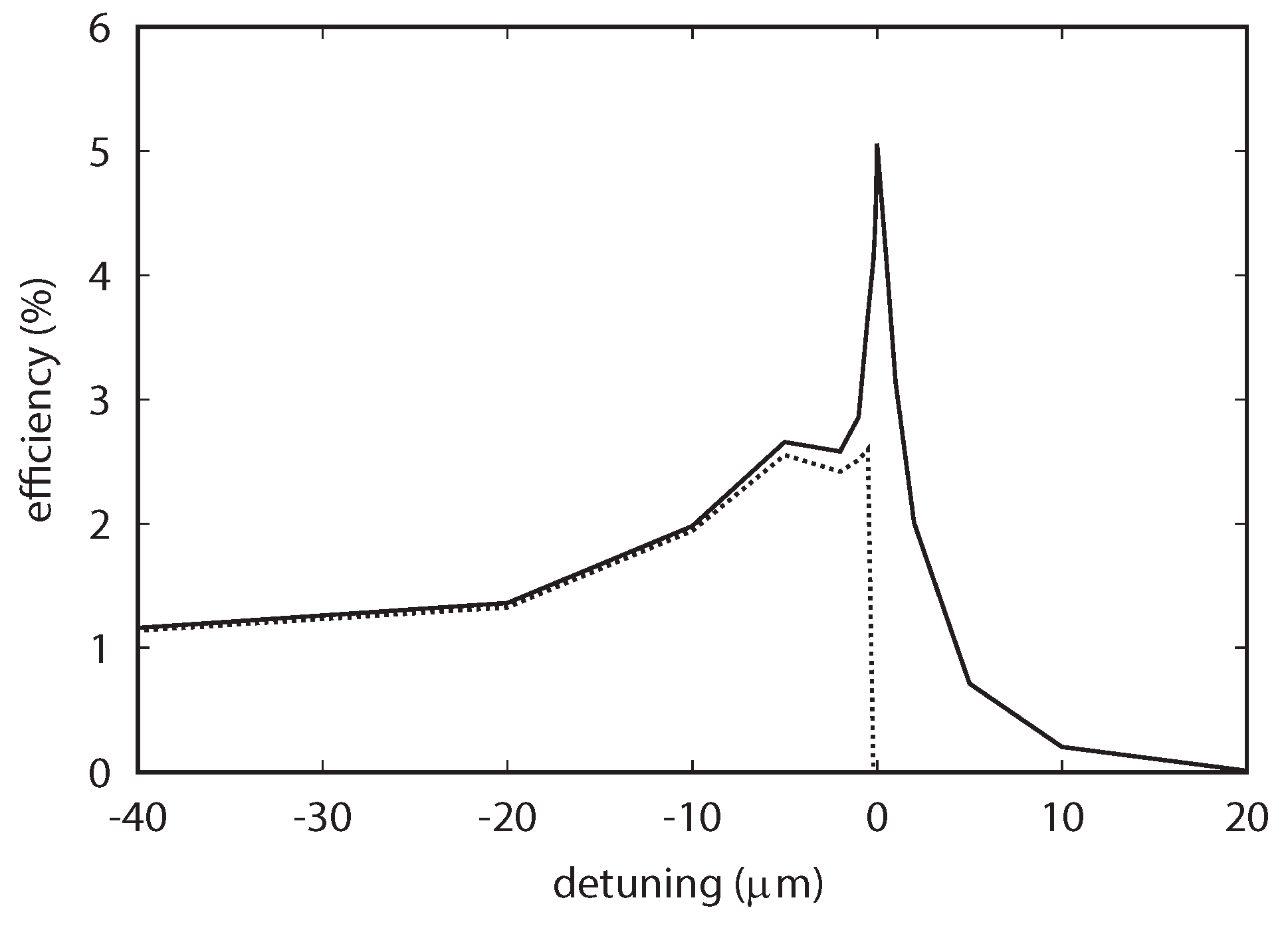
In the experiment, the undulator parameter, , was varied to change the FEL gain. Detuning curves for three different undulator parameters are plotted in Figure 2, which shows that the high-efficiency lasing at only occurs at and . This result suggests the existence of the FEL gain threshold for the lasing at . The FEL gain threshold is discussed with numerical simulations in Section 3.
The lasing at negative cavity-length detuning () has been studied analytically by supermode theory [7,8,11]. The analytical studies revealed that the lasing behavior of short-pulse FELs, in which the bunch length is shorter than the slippage distance, shows various aspects according to the gain, loss, and cavity length detuning: single supermode lasing with a smooth temporal profile, limit cycle lasing with a multi-peak pulse, and chaotic lasing with many spikes in a pulse.
The lasing at the zero detuning length observed at the JAERI-FEL is distinguished from the normal FEL lasing at by two unique features: high extraction efficiency and generation of an isolated few-cycle optical pulse that survives even after the onset of saturation. The high extraction efficiency is corresponding to the sharp peak in the detuning curve in Figure 1. The other feature, the generation of an isolated few-cycle pulse, was first suggested by numerical simulation [12,13] and later confirmed experimentally [14].
Figure 3 and Figure 4 show results of the simulation to reproduce the JAERI-FEL lasing at the zero detuning length [13]. The FEL pulse shows linear evolution rather than exponential growth. The temporal shape of micropulses in Figure 4, an exponential lobe of the leading edge and the main peak followed by ringing, is identical to Burnham–Chiao ringing of superradiance from atomic systems [15] and consistent with the pulse shape at the weak superradiance in the high-gain FEL amplifier [4,16] and the numerical result for superradiance in a short-pulse FEL oscillator [17].
The simulation result shows that an isolated (or solitary) few-cycle optical pulse evolves in an FEL oscillator at and the pulse survives after the onset of saturation in marked contrast to the lasing at , where a few-cycle pulse generated at the transient regime turns into a chaotic lasing after the saturation.
It should be noted that Figure 4 suggests an evolution of a superluminal pulse, which moves with a group velocity larger than the velocity of light in vacuum during the linear growth at the early stage of the macropulse. Such superluminal FEL pulse also appears in FEL amplifiers of superradiant regime [18,19].
It is known that the superluminal propagation may occur in short-distance tunneling phenomena [20] and long-scale unstable systems of atoms under an inverted population condition [21]. The superluminal propagation of neutrinos from supernovae is also studied [22]. The superluminal propagation of an optical pulse observed in the FEL oscillator has an obvious similarity to the case of the atomic systems under an inverted population condition. The peak of the FEL pulse, which has an interaction with a gain media, propagates a long distance faster than the speed of light.
The superluminal pulse evolution shown in Figure 4 can be thought of as a pulse-reshaping phenomenon in atomic systems with inverted populations [21] and the group velocity larger than the vacuum speed of light does not imply any violation of causality. The leading edge of the pulse grows dominantly at the early stage of the macropulse (the left figure), while the trailing part behind the main peak attenuates due to the energy transfer from the optical pulse to the electrons.
In the quantum limit, the superluminal effects in the unstable atomic systems are strongly suppressed due to the smallness of the wave packet’s tail containing only a few photons [23]. In the FEL oscillators, the superluminal pulse contains a number of photons and can be considered as a classical system rather than a quantum system.
Few-cycle pulse generation at the lasing was experimentally confirmed at the JAERI-FEL [14]. Figure 5 shows the result of autocorrelation measurement with fringe-resolved second-harmonic-generation (SHG) signals from a tellurium crystal at the JAERI-FEL. The FEL pulse duration was evaluated as 3.4 optical cycles (FWHM) without taking frequency chirp into account. Numerical simulations with the JAERI-FEL parameters reproduced the experimental result of the pulse duration and suggested that the pulse could be as short as 1.5 cycles after chirp compensation.
Another important subject revealed in the JAERI-FEL analysis is the role of shot noise at the lasing. We discuss this subject later in Section 4.
2.3. Experiments at KU-FEL
KU-FEL is an FEL oscillator driven by a 40-MeV S-band normal conducting linac at Kyoto University. The FEL is operated to provide FEL pulses from 3.4 to 26 m for user experiments [24]. Lasing with high-extraction efficiency at KU-FEL was recently achieved by dynamic cavity desynchronization (DCD) [25], modulation of RF phase for the klystron input signal to alter the electron bunch interval during a macropulse of a limited length, 6.5 s. The parameters for the DCD, timing and depth of the modulation, were optimized to maximize the extraction efficiency.
Extraction efficiencies of 5% and 9.4% were obtained with the thermionic emission mode and the photoemission mode of the RF gun, respectively [26,27]. The experimental parameters were as follows: electron beam energy 27.0 MeV, expected FWHM bunch length 90–180 m, FEL wavelength 11.6 m, the number of undulator periods 52, cavity round trip loss 3%, and macropulse duration 6.5 s. The bunch charge in the thermionic emission mode altered from 25 to 55 pC in a macropulse due to the back-bombardment effect. The bunch charge in the photoemission mode was 190 pC. These parameters satisfy the condition for superradiance in a short-pulse FEL oscillator.
In the experiment, FEL extraction efficiency was evaluated from the energy spectrum of the spent electron beam after the undulator. Figure 6a shows the evolutions of the energy distribution of the electron beam obtained from the experiment in the thermionic emission mode, in which we can see that a large part of electrons lose their energy with the FEL interaction. The maximum average energy loss at the end of the macropulse is approximately 1.5 MeV, which corresponds to a relative average energy loss of 5.5%.
The energy spectrum at the high-efficiency FEL lasing was well reproduced by a one-dimensional simulation as shown in Figure 6b. In the simulation, the electron bunch was assumed to have a rectangular temporal shape of 1 ps and 40 pC with no energy spread. The FEL parameter, , was 0.0034 and the cavity loss was 3%. To simulate the best DCD condition in the experiment, the cavity detuning for the simulation was altered from to 0 m at the 60th round trip, which is 2 s in the macropulse.
We can see that the energy evolution maps obtained from the experiment and the simulation have a common structure of three branches. The first branch is the component for continuously decreasing energy (A in Figure 6b), which corresponds to electrons trapped in the bucket to be efficiently decelerated. Figure 6 shows that a large part of electrons belong to the first branch. This is the reason a high extraction efficiency was realized in the experiment. The second branch is the component with constant energy (B in Figure 6b), which shows the existence of electrons untrapped in the bucket, but the amount is not very large. The third branch is the component whose energy is slightly increased and soon disappears (C in Figure 6b). The third branch indicates that a small fraction of the electron beam is slightly accelerated in the early stage of the energy extraction.
For the further examination of the three branches, Figure 7 plots the longitudinal phase space distribution of the two-wavelength slices at the center of the electron bunch and at different longitudinal positions in the undulator corresponding to the end of the macropulse in Figure 6b. From the plot, we can confirm that the electrons are split into three branches according to the initial phase.
3. Scaling Law of the Superradiance in FEL Oscillators
In the superradiance at two-level systems, the number of emitted photons () and the pulse duration () scale as the number of two-level emitters (N): and . Analytical studies revealed that the same superradiance scaling appears in FEL oscillators operated at small negative detuning length [7,8] and perfectly synchronized cavity length [17].
In short-pulse FEL oscillators operated at small negative detuning length, it was analytically derived that the peak power, , efficiency, , and the number of optical cycles, , follow the scaling law given by a function of the fundamental FEL parameter, , bunch length, , cooperation length, , and round-trip loss of the optical cavity, : [7]
and the maximum efficiency occurs approximately for the cavity length shortening . The above scaling law is valid for an FEL oscillator driven by an electron bunch shorter than the slippage length, where the lasing behavior can be described by eigenmode (supermode) analysis. The scaling law was experimentally confirmed at the FEL oscillator, FELIX, in which the peak power, extraction efficiency, pulse energy were measured with changing the bunch charge [9].
For the further discussion in the present paper, we convert the fundamental FEL parameter into the Colson’s dimensionless current , which is commonly used for analyzing small-gain FEL oscillators [28]. Following the relation , we can rewrite Equation (2) as
The left-hand side, , is the extraction efficiency normalized by the number of undulator periods. The dimensionless current, , is proportional to the peak current and the above equation is valid for a square-shaped bunch with a constant peak current. For an electron bunch with an arbitrary temporal profile, the above equation should read
Since the dimensionless current is proportional to the beam current , we can again confirm the efficiency scales to the number of electrons as .
In the JAERI-FEL experiment, we observed an FEL efficiency exceeding the above scaling law of superradiant FEL oscillator [29]. This is because high efficiency lasing obtained at the perfect synchronization of the optical cavity cannot be covered by the supermode analysis.
As we can see from the simulation result in Figure 4, an isolated pulse evolves in an FEL oscillator operated at the perfect synchronization. Generation of such isolated pulse in superradiant FEL oscillators was discussed in a previous paper to derive a set of equations, which have the approximate solution of a hyperbolic secant pulse [30]. In the study, however, a handy scaling formula of the FEL efficiency for arbitrary experimental parameters was not explicitly given. Thus, we conducted a series of numerical simulations to obtain the scaling of the FEL efficiency for arbitrary FEL operation parameters.
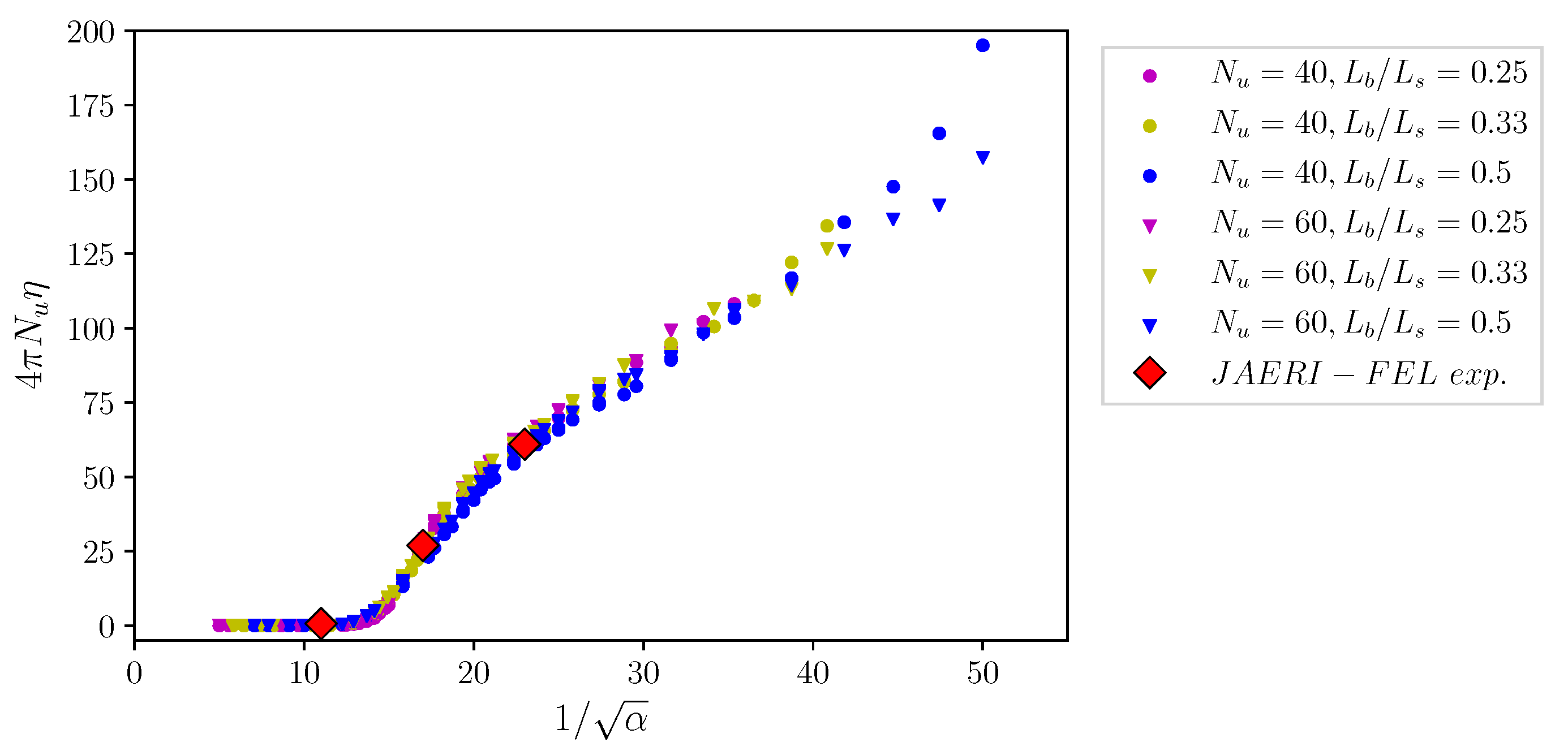
The simulations were carried out by a one-dimensional time-dependent FEL code same as our previous study [14]. We chose the number of undulator periods at , and the bunch length normalized to the slippage length at , and varied the normalized cavity loss, , in the range of . Figure 8 plots the simulation results of the normalized FEL efficiency at the perfectly synchronized cavity length, , as a function of , the inverse square root of the normalized cavity loss. In the simulations, a rectangular-shaped bunch was assumed and the shot noise was introduced according to the standard algorithm [31]. The results of the JAERI experiment are also plotted.
We can confirm from the simulation results that the FEL efficiency at the perfectly synchronized cavity length is given by a function of a single variable , the normalized cavity loss. The simulation results also suggest that there is a threshold, , for the lasing at . The threshold for the evolution of a hyperbolic secant pulse and the extraction efficiency in superradiance FEL are analytically discussed in previous papers [17,30]. Derivation of a mathematical expression to fit the simulation results and comparison with the analytical studies remain future works.
4. Role of Shot Noise
In FEL oscillators, as in single-pass SASE-FELs, the evolution of optical pulse starts from shot noise resulting from the random distribution of electrons in the bunch. In general, the shot noise has little effect on the FEL lasing after the onset of saturation because the intensity of the shot noise within the FEL bandwidth is negligibly small. In Section 2.2, we note that the role of shot noise in FEL oscillators with the perfectly synchronized cavity is different from the normal FEL lasing. The shot noise plays an intrinsic role in maintaining the FEL lasing at even after the onset of saturation.
In a short pulse FEL oscillator, the trailing part of the optical pulse is amplified as a result of coherent emission from the electron bunch at the slippage region. With a negative cavity-detuning length, the amplified part is pushed forward to the leading edge of the pulse. This intra-pulse feedback of the optical field is the source of the exponential growth of an optical pulse in FEL oscillators.
In FEL oscillators with the perfectly synchronized cavity, there is no intra-pulse feedback and the pulse evolution obeys linear growth instead of exponential growth [17]. The leading part of the optical pulse at the lasing contains incoherent shot noise with random amplitude and phase even after the onset of saturation. The amplitude and phase in the entire FEL pulse are governed by the interaction between the electrons and the radiation initiated by the shot noise in the leading part. As a result of random shot noise, the FEL pulse intensity exhibits slowly evolving fluctuation during a macropulse, as shown in Figure 3. We see, in the next section, that the shot noise introduces fluctuation in the carrier frequency and phase of an optical pulse evolving in an FEL oscillator operated at .
The role of shot noise at the lasing can be confirmed by a numerical simulation. We conducted two simulations with parameters for the JAERI-FEL experiment: one with shot noise determined by the standard formula [31] and the other with shot noise of that. Detuning curves for two cases are plotted in Figure 9, in which we can see that the simulation with the standard shot noise gives FEL lasing with large extraction efficiency around zero-detuning length, but FEL lasing does not occur with a detuning range of for the smaller shot noise.
5. Stabilization of Carrier-Envelope Phase
Generation of a few-cycle laser pulse and its application for studying ultrafast physics in laser–matter interaction is one of the topical research subjects in advanced laser science [32,33,34,35]. In laser-matter interaction at the strong field regime, the laser oscillating electric field sways electrons of a target atom and causes tunneling ionization when the laser intensity is comparable with the atomic nucleus potential. The laser–matter interaction in the strong field regime must be studied in terms of the oscillating electric field rather than the instantaneous intensity. Carrier-envelope phase (CEP) is, therefore, important for characterizing a few-cycle laser pulse for the strong-field regime. Carrier-envelope phase of a laser pulse is also indispensable for the application of a mode-locked laser to optical frequency combs, in which the pulse-to-pulse carrier-envelope offset is stabilized for a broadband optical frequency comb to determine all line frequencies [36]. In solid-state lasers, stabilization and control of the CEP of few-cycle laser pulses can be realized with either passive or active manner [33,37]. As discussed in the previous sections, a short-pulse FEL oscillator operated at the perfectly synchronized cavity length can generate an isolated few-cycle FEL pulse, which can be utilized for exploring ultrafast science. Since FEL oscillators have unique features of wavelength tunability and high-repetition-rate availability, FEL will be an attractive photon source complimentary to solid-state femtosecond lasers.
Such few-cycle pulses from FEL oscillators would be more attractive, if the carrier-envelope phase of the pulse were stabilized. However, CEP stabilization in FEL oscillators has never been demonstrated because the evolution of FEL pulses is initiated by the uncontrollable shot noise. In the few-cycle lasing at the perfectly synchronized cavity, the leading part of the optical pulse contains incoherent shot noise with random amplitude and phase. The amplitude and phase in the entire FEL pulse are governed by the interaction between the electrons and the radiation initiated by the shot noise in the leading part. Consequently, the carrier frequency and phase of the FEL pulses are not stabilized.
A numerical simulation suggested possible stabilization of a few-cycle superradiant FEL pulse by utilizing Michelson resonator, but the stabilization of CEP was not discussed [38]. Another method was proposed for full stabilization of carrier-envelope phase of the few-cycle FEL pulse generated in an FEL oscillator [39]. The method is based on a CEP-stable external seed laser to fix the phase and amplitude of the leading part of the FEL pulse.
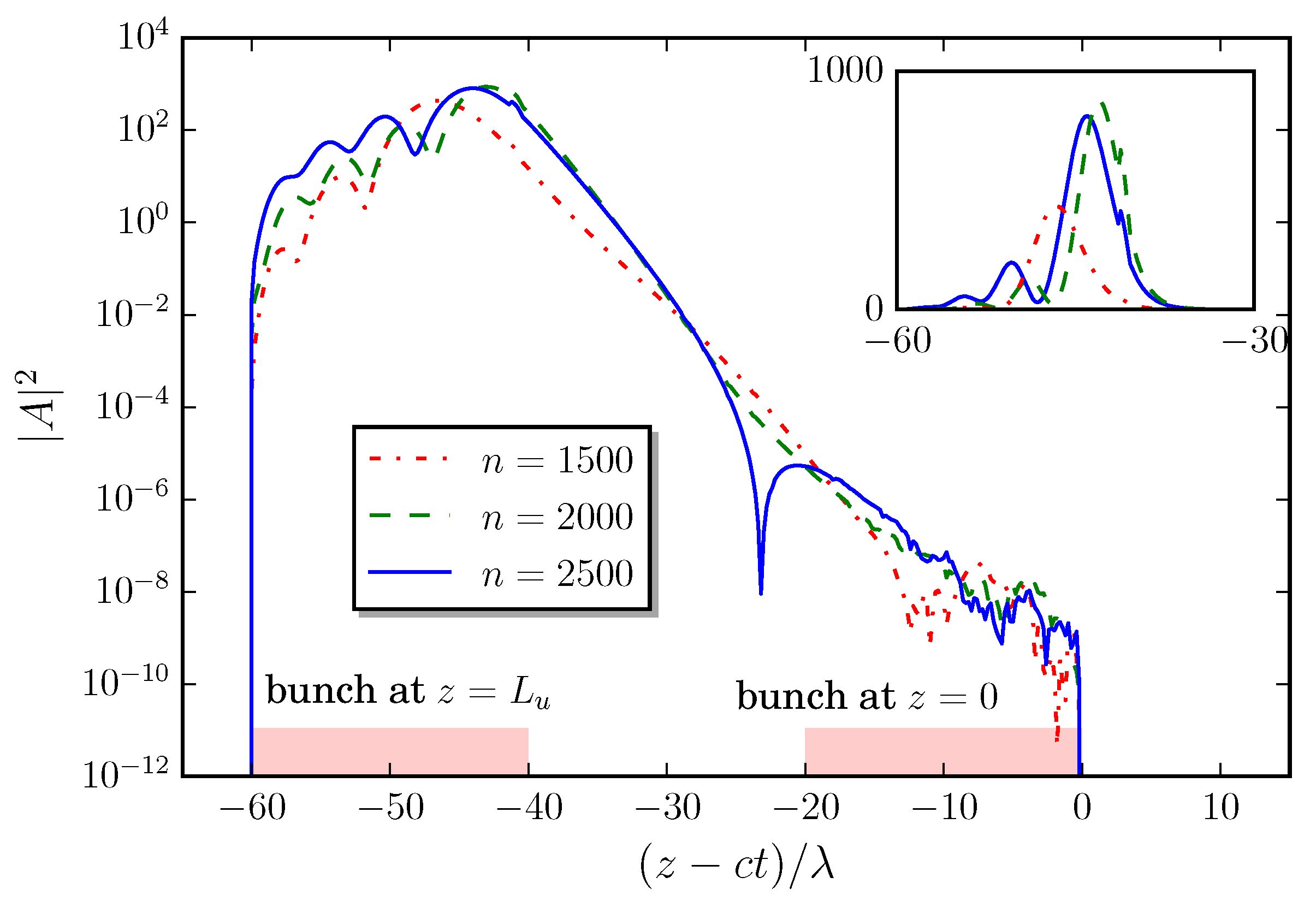
Simulation results to demonstrate the CEP stabilization are presented in Figure 10 and Figure 11. The simulation parameters are listed in Table 1, in which the parameters for the JAERI experiments are shown for comparison. Figure 10 shows the temporal profiles of FEL pulses after 1500, 2000, and 2500 round trips in a perfectly synchronized FEL oscillator. In this plot, the longitudinal coordinate is defined such that the leading edge of the electron bunch is located at the undulator entrance, , at the reference time, . The pulse intensity is expressed as a dimensionless value normalized by the high-gain FEL parameter such that determines the ratio between the energy densities of the FEL radiation and the resonant electron beam [4]. The position and profile of the electron bunch at the entrance and exit of the undulator are also depicted to demonstrate that the FEL lasing is in the strong-slippage regime.
Figure 10 illustrates the characteristics of FEL pulses evolving in a high-gain and strong-slippage FEL oscillator with a perfectly synchronized optical cavity. The optical pulse consists of an exponential lobe of the leading edge and the main peak followed by ringing. The duration of the main peak, 4.4 cycles (FWHM) after 2500 round trips, is much shorter than that of the electron bunch. The pulse height and peak position are not fixed and exhibit continuous variation along with the pulse energy changes. The main peak followed by ringing is common to superradiance observed in two-level systems [15] and identical to previous results for the analysis of a high-gain FEL amplifier [4] and a perfectly synchronized FEL oscillator in the transient regime [17], both of which indicated the FEL lasing to be superradiance. The electron bunch slips backward inside the optical pulse during the motion in the undulator. In this motion, the electron bunch forms microbunch through interaction with the optical field and then emits strong radiation in the slippage region. The emission in the slippage region is accompanied by frequency down chirp to keep emission along electron energy decreasing [14]. This down chirp contributes to a large FEL conversion efficiency, but introduces a large energy spread in the spent electron beam as well. In a conventional FEL oscillator, the optical cavity length is shortened so that the optical pulse is pushed forward every round trip to enlarge a single-pass gain by introducing strong electron bunching with a high-intensity optical field at an early section of the undulator. The cavity-length shortening achieves feedback of radiation power from the tail to the head of optical pulse, which also communicate optical phase and frequency from the tail to the head. As a result, the cavity length shortening constrains phase correlation inside the optical pulse, which prohibits the strong down chirp observed in the lasing at the perfectly synchronized cavity.
The logarithmic plot of the FEL pulse in Figure 10 shows that the dynamic range of laser pulse intensity from the leading edge to the peak is greater than . The leading part of the optical pulse contains incoherent shot noise with random amplitude and phase. The amplitude and phase of the field in the exponential envelope, the main peak and the ringing are all governed by the interaction between the electrons and the radiation initiated by the shot noise in the leading part. Consequently, the carrier frequency and phase of the FEL pulses are not stabilized and vary over round trips.
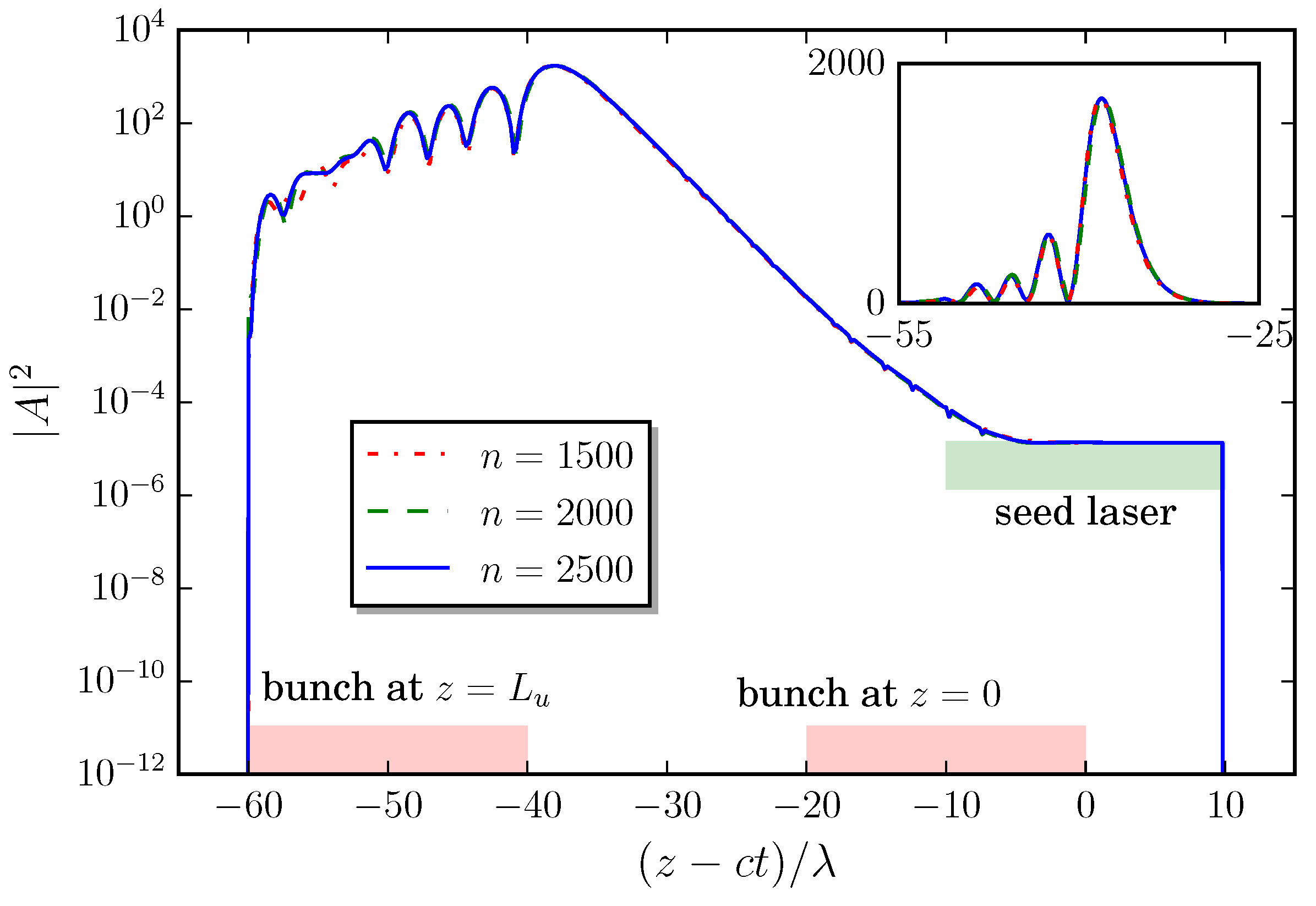
Figure 11 shows FEL pulses obtained in a simulated FEL oscillator with injection seeding, where all the parameters are the same as in Figure 10. The seed laser pulse is assumed to have the resonant wavelength, an intra-cavity intensity of , and temporal duration of with stable CEP. The seed pulse timing is chosen such that a half of the seed pulse overlaps with the FEL pulse and the rest is out of the FEL pulse to indicate the seed laser intensity not affected by the FEL interaction. In Figure 11, we can see that the seed laser efficiently stabilizes the FEL oscillator with a perfectly synchronized cavity. The FEL pulse after the saturation retains an almost identical temporal shape: the main pulse of 3.8 cycles (FWHM) followed by periodic ringing. The small fluctuations observed in the ringing are attributed to the effect of shot noise, whose intensity is three orders of magnitude smaller than that of the seed pulse.
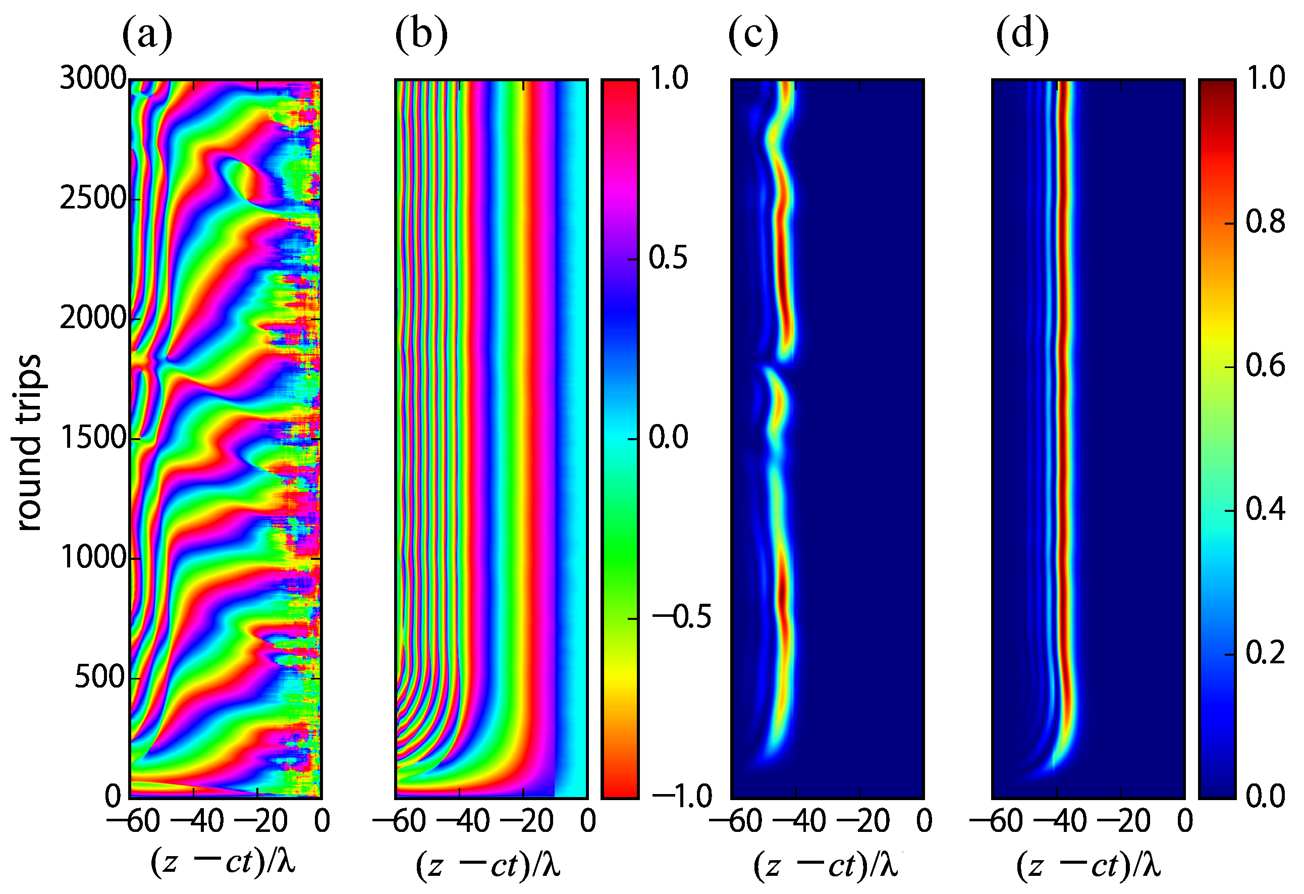
The effects of the CEP stabilization can be clearly confirmed in Figure 12, which shows instantaneous intensity and phase of FEL pulses evolving in the perfectly synchronized cavity for the two cases without and with a seed laser. The instantaneous phase, , is defined such that the complex field is expressed as , where is the FEL resonance frequency. The simulation parameters are the same as Figure 10 and Figure 11, respectively. A few-cycle FEL pulse is established after a start-up period, ∼500 round trips. In the few-cycle FEL pulse, the carrier phase is continuous whole through the pulse except for the leading edge. Since the pulse leading edge is a free boundary governed by shot noise, the pulse always suffers from fluctuation introduced by the shot noise. As a result, the pulse has a chance to lose the memory of the original carrier phase or to be replaced by another pulse. These variations of FEL pulse occur in the time scale of the FEL pulse evolution from the shot noise to the saturation, ∼500 round trips in the case. In the lasing without a seed laser, the phase of the leading part has fluctuation due to the shot noise, which makes pulse shape and CEP unstable over many round trips. The FEL pulse evolution with an external seed laser exhibits a quite different aspect, in which the pulse shape and CEP after the onset of saturation are stabilized. The nonlinear phase advance from the head to the tail of pulses in Figure 12a,b corresponds to the frequency down chirp [14].
6. Proposal of FEL-HHG
High-harmonic generation (HHG) is a nonlinear process to realize the emission of the high harmonics of the incident beam from a target illuminated by an intense laser pulse. Recent development of solid-state laser technologies has realized a generation of isolated attosecond pulses in ultraviolet and X-ray wavelengths via HHG in gas and solid-state targets [32,34,40]. As such attosecond photon sources are routinely available in laboratories, attosecond science is becoming an active research field, in which ultrafast dynamics in atoms and molecules is investigated in detail. In addition, the HHG is an interesting research subject as an interaction of strong laser field with atoms and molecules.
Combination of HHG and an FEL was first examined at a SASE FEL, where an ultraviolet pulse from HHG was used as a seed laser to stabilize the shot-to-shot variation in spectrum and energy of the SASE-FEL pulses [41]. The experiment can be called HHG-seeded FEL or HHG-FEL. To the contrary, an optical pulse generated from an infrared FEL can be used, in principle, to drive HHG, that is FEL-HHG [42].
There are several trends in the development of HHG photon sources. One of the major trends is increasing the photon energy (or decreasing the photon wavelength) available in HHG photon sources. The highest photon energy so far demonstrated is a generation of a bright supercontinuum that spans from the ultraviolet to more than 1.6 keV [43]. The experiment adopted a mid-infrared laser pulse at a wavelength of λ = 3.9 μm as a driver of HHG. Theoretical and experimental studies revealed that the HHG cut-off energy scales as in the phase-matched condition [43,44]. The scaling law implies possible extension of the HHG photon energy beyond 1.6 keV by utilizing a mid-infrared laser pulse, m. However, pushing the cut-off energy above 1.6 keV has not been realized mainly due to the lack of mid-infrared laser pulses satisfying conditions for HHG, wavelength, pulse energy, pulse duration, and repetition. Thanks to the wavelength tunability and the high-repetition-rate availability, an FEL oscillator is a potential driver of HHG photon sources complementary to conventional solid-state femtosecond lasers.
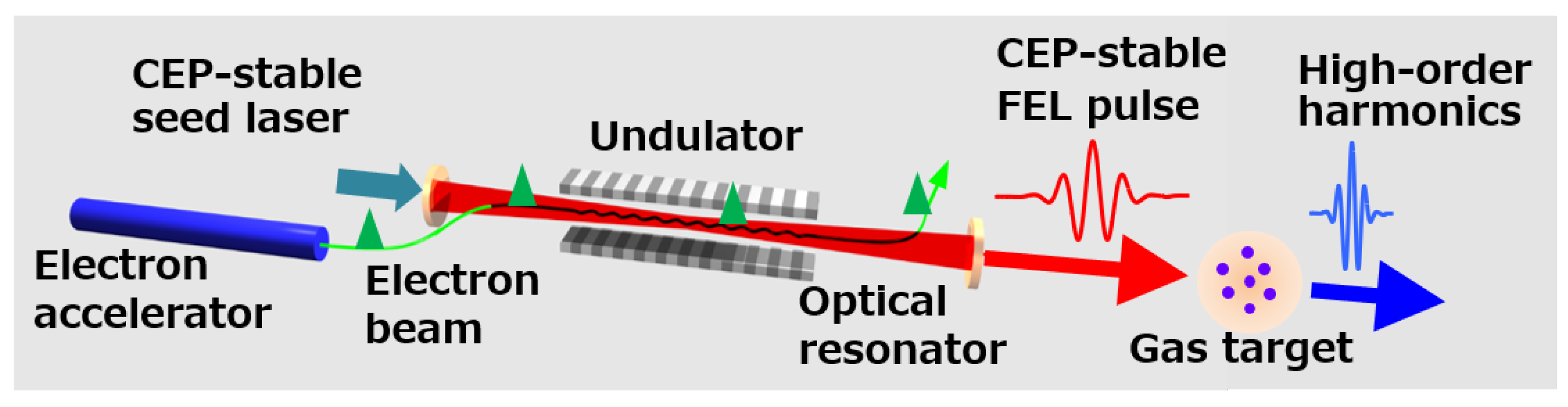
We proposed a concept of FEL-HHG based on superradiant FEL at a perfectly synchronized FEL oscillator. Figure 13 shows a schematic view of the proposed FEL-HHG. The FEL wavelength should be determined from the requirements of attosecond pulse generation in HHG. For a generation of attosecond pulses whose wavelength covers from ultraviolet to X-ray above 1 keV, we assume the FEL wavelength of 2–6 m from the scaling law of HHG cut-off energy. A superconducting linac is adopted to deliver a CW pulse train to the FEL-HHG.
Example sets of FEL-HHG parameters are listed in Table 2, where the FEL wavelength is 2–6 m and the parameters are chosen so that FEL pulse energy is 0.5 mJ. We consider such FEL oscillators can be constructed with existing technologies: a photo-cathode electron gun [45] and superconducting RF cavities [46].
7. Research Program for FEL-HHG
A 10-year research program (2018–2027) has been funded to develop basic technologies for the FEL-HHG [47]. In the program, we are conducting research and development towards the FEL-HHG at two FEL facilities, KU-FEL at Kyoto University and LEBRA-FEL at Nihon University, both of which are infrared FEL oscillators driven by normal conducting linear accelerators. These facilities of infrared FELs can be exploited for basic technologies development and a following proof-of-concept experiment of FEL-HHG, whereas FEL-HHG for a full-scale application of attosecond ultraviolet and X-ray pulses should be realized by a superconducting linac FEL oscillator.
The research subjects to be conducted are: (1) generation and characterization of few-cycle mid-infrared pulses from the FEL oscillators; (2) enhancement of FEL pulse energy by an external optical cavity; and (3) scheme for CEP stabilization of FEL pulses including the development of a mid-infrared seed laser. We plan to explore these subjects in the first six years, 2018–2023, and proceed to a proof-of-concept experiment of the FEL-HHG at two facilities.
In the following sections, we describe the plan and the current status of our research program.
7.1. Pursuing the Ultimate Extraction Efficiency
As described in Section 2.3, the FEL lasing of 5.5% extraction efficiency was realized in KU-FEL with 25–55-pC electron bunches from the 4.5-cell RF gun operated at the thermionic emission mode [26]. After the upgrade of the gun drive laser system, we demonstrated the FEL extraction efficiency of 9.4% with 190-pC electron bunches generated by the same RF gun operated at the photoemission mode [27]. For the further increase of FEL pulse energy, a new 1.6-cell RF gun is under fabrication to provide a train of 1-nC bunches.
The FEL cavity of KU-FEL is equipped with two gold-coated copper mirrors, one of which has an on-axis small hole for outcoupling. The hole-coupled gold-coated copper mirror can be utilized in a wide range of FEL wavelength, but introduces a large diffraction loss. The total round-trip loss of the FEL cavity is expressed as
where is a fraction of outcoupling from the cavity and and are cavity loss due to the imperfect reflectivity of the mirror and the diffraction, respectively. In a cavity with a hole-coupled mirror, the diffraction loss is always larger than the outcoupling, , due to the Babinet principle [48]. Therefore, a dielectric mirror with partial transmittance is preferable for the efficient outcoupling with keeping a small total loss. After the replacement of the mirror, we expect the total loss can be reduced from 3% with the hole-coupled mirror to 1% with a dielectric mirror without changing the outcoupling fraction.
We reviewed in Section 3 that the extraction efficiency and the pulse duration for the FEL lasing at scale as a single parameter, , the normalized cavity loss. In the research program, we plan to conduct FEL experiments at KU-FEL with changing the bunch charge and the optical cavity configuration to confirm the scaling law beyond the JAERI-FEL parameter, the extraction efficiency of 9% at the experimental parameter corresponding to [29]. Experiments for FEL pulse measurements are also planned for characterizing few-cycle lasing at the high-efficiency parameters.
7.2. Stacking FEL Pulses in an External Cavity
The FEL oscillator at LEBRA covers 0.827–6.1 m with a macro-pulse of 20 s [49]. We plan to explore FEL pulse stacking in an external optical cavity utilizing the advantage of the relatively long macropulse. Stacking laser pulses in an external cavity is a common technology to enhance the energy of pulses from a mode-locked laser for HHG [50] and other applications [51]. Generation of high-harmonics from a gas target is possible either using stored pulses in an external cavity or using a laser pulse dumped from a cavity. Such cavity dump can be performed with semiconductor photo-switches [52].
An experiment of FEL pulse stacking was conducted at the superconducting linac FEL at Stanford University. They demonstrated the accumulation of micropulses with more than 75 times the energy of the incident FEL pulses [53]. The Stanford FEL was operated at a quasi-CW mode and the external cavity worked in the steady-state mode, in which the injected pulse energy was balanced with the cavity loss. In normal-conducting-linac FELs, pulse stacking in the transient mode is suitable for maximizing the stored pulse energy [54]. In LEBRA-FEL, we will optimize the external cavity to realize FEL pulses for HHG experiments.
For the pulse stacking experiment, we installed an external cavity at an experimental room of LEBRA-FEL. The cavity is a bow-tie shape and the frequency of the cavity is chosen at 44 MHz, double of the FEL cavity frequency. The cavity length must be controlled precisely to stack successive pulses coherently. The FEL pulse train of 20 s is, however, not long enough to tune the cavity length. Thus, we use a fiber laser oscillator for the cavity tuning. As a preliminary tuning of the cavity, we injected laser pulses from the fiber oscillator and confirmed multiple recirculation of injected laser pulses in the cavity. Further tuning of the external cavity is in progress.
In parallel with the experimental work, we are conducting simulation studies to predict the performance of the pulse stacking with optimized cavity parameters, transmittance of the input coupler, and recirculation path length. In the simulations, we use a three-dimensional FEL code, GENESIS [55], coupled with a wave propagation code to calculate the iterative interaction of an FEL pulse and electron bunches [56].
7.3. CEP-Stable Laser for Seeding FEL Oscillators
A seed laser for the CEP-stabilization in an FEL oscillator must provide CEP-stable laser pulses with moderate pulse energy, ∼1 nJ. In addition, the laser pulse should be synchronized to the electron bunch repetition. Since the generation of such laser pulses below 3 m is well-established, we focus our efforts on the development of seed lasers at wavelengths longer than 3 m. We designed a laser system comprising a mode-locked fiber oscillator and a fiber amplifier followed by a difference frequency generation between the light pulse of the fiber laser and its wavelength shifting. The laser system is under development [57].
Apparatuses for the HHG experiment such as a gas cell, a vacuum chamber with a differential pumping system, and a spectrometer for ultraviolet and X-ray are to be designed and fabricated at QST and shipped to Kyoto University and Nihon University for the proof-of-concept experiments of FEL-HHG.
8. Summary
Evolution of few-cycle FEL pulses was experimentally confirmed in FELIX, JAERI-FEL, and other short-pulse FEL oscillators. From analytical and numerical studies, it was found that the few-cycle FEL lasing in the short-pulse FEL oscillators is explained in the frame of superradiance, cooperative emission from self-bunched systems, and superradiance in high-gain FEL amplifiers.
The few-cycle lasing appears in a high-gain short-pulse FEL oscillator, whose cavity length has a small negative or zero detuning length from the perfectly synchronized condition to the electron bunch repetition. In the small negative detuning, a few-cycle pulse evolving in the transient regime turns into chaotic lasing after the onset of saturation. In the lasing at zero detuning length, an isolated (or solitary) few-cycle pulse survives even after the onset of saturation, but has slow fluctuation in the peak position and the intensity due to the shot noise of the electron beam. The fluctuation also results in a random drift of the carrier-envelope phase of the few-cycle FEL pulse. A numerical simulation suggested that the carrier-envelope phase of the few-cycle FEL can be stabilized by utilizing a CEP-stable external seed laser.
Thanks to the wavelength tunability and the high-repetition-rate availability, the few-cycle optical pulses from FEL oscillators have unique applications. High-harmonic generation (HHG) from gas and solid targets is a promising application of the few-cycle FEL pulse. High-harmonic generation driven by FEL, FEL-HHG, enables one to explore ultrafast science with attosecond ultraviolet and X-ray pulses with a MHz repetition rate, which is difficult with HHG driven by solid-state lasers. A research program has been launched to develop technologies for the FEL-HHG and to conduct a proof-of-concept experiment of FEL-HHG. The research program encompasses generation and characterization of few-cycle mid-infrared pulses in FEL oscillators, stacking of FEL pulses in an external cavity, and a seed laser for stabilization of carrier-envelope phase of the FEL pulses.
Funding
This research was supported in part by MEXT Quantum Leap Flagship Program (MEXT Q-LEAP) Grant Number JPMXS0118070271.
Acknowledgments
The author is grateful to his colleagues from the JAERI FEL, E.J. Minehara, M. Sawamura, R. Nagai, N. Nishimori and N. Kikuzawa, who provided insight and expertise that greatly contributed to the JAERI-FEL experiment. The author thanks the members of the Q-LEAP program, K. Kawase, H. Ohgaki, H. Zen, Y. Hayakawa, T. Sakai, Y. Sumitomo, M. Shimada and T. Miyajima, for helpful discussion.
Conflicts of Interest
The authors declare no conflict of interest.
References
- Bonifacio, R.; Casagrande, F. The superradiant regime of a free electron laser. Nucl. Instrum. Methods Phys. Res. Sect. A Accel. Spectrometers Detect. Assoc. Equip. 1985, 239, 36–42. [Google Scholar] [CrossRef]
- Dicke, R.H. Coherence in Spontaneous Radiation Processes. Phys. Rev. 1954, 93, 99–110. [Google Scholar] [CrossRef] [Green Version]
- Gover, A.; Ianconescu, R.; Friedman, A.; Emma, C.; Sudar, N.; Musumeci, P.; Pellegrini, C. Superradiant and stimulated-superradiant emission of bunched electron beams. Rev. Mod. Phys. 2019, 91, 035003. [Google Scholar] [CrossRef] [Green Version]
- Bonifacio, R.; Casagrande, F.; Cerchioni, G.; Salvo Souza, L.; Pierini, P.; Piovella, N. Physics of the high-gain FEL and superradiance. La Riv. Del Nuovo Cimento 1990, 13, 1–69. [Google Scholar] [CrossRef]
- Bakker, R.J.; van der Geer, C.A.J.; Jaroszynski, D.A.; van der Meer, A.F.G.; Oepts, D.; van Amersfoort, P.W. Broadband tunability of a far-infrared free-electron laser. J. Appl. Phys. 1993, 74, 1501–1509. [Google Scholar] [CrossRef]
- Knippels, G.M.H.; Mols, R.F.X.A.M.; van der Meer, A.F.G.; Oepts, D.; van Amersfoort, P.W. Intense Far-Infrared Free-Electron Laser Pulses with a Length of Six Optical Cycles. Phys. Rev. Lett. 1995, 75, 1755–1758. [Google Scholar] [CrossRef] [PubMed]
- Piovella, N.; Chaix, P.; Shvets, G.; Jaroszynski, D.A. Analytical theory of short-pulse free-electron laser oscillators. Phys. Rev. E 1995, 52, 5470–5486. [Google Scholar] [CrossRef]
- Chaix, P.; Piovella, N.; Grégoire, G. Superradiant, single-supermode and nonlinear regimes of short pulse free electron laser oscillators. Phys. Rev. E 1999, 59, 1136–1151. [Google Scholar] [CrossRef]
- Jaroszynski, D.A.; Chaix, P.; Piovella, N.; Oepts, D.; Knippels, G.M.H.; van der Meer, A.F.G.; Weits, H.H. Superradiance in a Short-Pulse Free-Electron-Laser Oscillator. Phys. Rev. Lett. 1997, 78, 1699–1702. [Google Scholar] [CrossRef]
- Nishimori, N.; Hajima, R.; Nagai, R.; Minehara, E.J. Sustained Saturation in a Free-Electron Laser Oscillator at Perfect Synchronism of an Optical Cavity. Phys. Rev. Lett. 2001, 86, 5707–5710. [Google Scholar] [CrossRef]
- Dattoli, G.; Marino, A.; Renieri, A. A multimode small signal analysis of the single pass free electron laser. Opt. Commun. 1980, 35, 407–412. [Google Scholar] [CrossRef]
- Hajima, R.; Nishimori, N.; Nagai, R.; Minehara, E.J. Analyses of superradiance and spiking-mode lasing observed at JAERI-FEL. Nucl. Instrum. Methods Phys. Res. Sect. A Accel. Spectrometers Detect. Assoc. Equip. 2001, 475, 270–275. [Google Scholar] [CrossRef]
- Hajima, R.; Nishimori, N.; Nagai, R.; Minehara, E.J. High-efficiency ultrashort pulse generation in a high-gain FEL oscillator near the perfect synchronism. Nucl. Instrum. Methods Phys. Res. Sect. A Accel. Spectrometers Detect. Assoc. Equip. 2002, 483, 113–118. [Google Scholar] [CrossRef]
- Hajima, R.; Nagai, R. Generation of a Self-Chirped Few-Cycle Optical Pulse in a FEL Oscillator. Phys. Rev. Lett. 2003, 91. [Google Scholar] [CrossRef]
- Burnham, D.C.; Chiao, R.Y. Coherent Resonance Fluorescence Excited by Short Light Pulses. Phys. Rev. 1969, 188, 667–675. [Google Scholar] [CrossRef]
- Bonifacio, R.; Piovella, N.; McNeil, B.W.J. Superradiant evolution of radiation pulses in a free-electron laser. Phys. Rev. A 1991, 44, R3441–R3444. [Google Scholar] [CrossRef]
- Piovella, N. Transient regime and superradiance in a short-pulse free-electron-laser oscillator. Phys. Rev. E 1995, 51, 5147–5150. [Google Scholar] [CrossRef]
- Watanabe, T.; Wang, X.J.; Murphy, J.B.; Rose, J.; Shen, Y.; Tsang, T.; Giannessi, L.; Musumeci, P.; Reiche, S. Experimental Characterization of Superradiance in a Single-Pass High-Gain Laser-Seeded Free-Electron Laser Amplifier. Phys. Rev. Lett. 2007, 98, 034802. [Google Scholar] [CrossRef] [PubMed]
- Yang, X.; Mirian, N.; Giannessi, L. Postsaturation dynamics and superluminal propagation of a superradiant spike in a free-electron laser amplifier. Phys. Rev. Accel. Beams 2020, 23, 010703. [Google Scholar] [CrossRef] [Green Version]
- Nimtz, G. On superluminal tunneling. Prog. Quantum Electron. 2003, 27, 417–450. [Google Scholar] [CrossRef]
- Chiao, R.Y. Superluminal (but causal) propagation of wave packets in transparent media with inverted atomic populations. Phys. Rev. A 1993, 48, R34–R37. [Google Scholar] [CrossRef] [PubMed]
- Jentschura, U.D.; Horváth, D.; Nagy, S.; Nándori, I.; Trócsányi, Z.; Ujvári, B. Weighing the neutrino. Int. J. Mod. Phys. E 2014, 23, 1450004. [Google Scholar] [CrossRef]
- Aharonov, Y.; Reznik, B.; Stern, A. Quantum Limitations on Superluminal Propagation. Phys. Rev. Lett. 1998, 81, 2190–2193. [Google Scholar] [CrossRef] [Green Version]
- Zen, H.; Suphakul, S.; Kii, T.; Masuda, K.; Ohgaki, H. Present Status and Perspectives of Long Wavelength Free Electron Lasers at Kyoto University. Phys. Procedia 2016, 84, 47–53. [Google Scholar] [CrossRef]
- Bakker, R.J.; Knippels, G.M.H.; van der Meer, A.F.G.; Oepts, D.; Jaroszynski, D.A.; van Amersfoort, P.W. Dynamic desynchronization of a free-electron laser resonator. Phys. Rev. E 1993, 48, R3256–R3258. [Google Scholar] [CrossRef]
- Zen, H.; Ohgaki, H.; Hajima, R. High-extraction-efficiency operation of a midinfrared free electron laser enabled by dynamic cavity desynchronization. Phys. Rev. Accel. Beams 2020, 23, 070701. [Google Scholar] [CrossRef]
- Zen, H.; Ohgaki, H.; Hajima, R. Record high extraction efficiency of free electron laser oscillator. Appl. Phys. Express 2020, 13, 102007. [Google Scholar] [CrossRef]
- Brau, C.A. Free-Electron Lasers; Academic Press, Inc.: San Diego, CA, USA, 1990. [Google Scholar]
- Nishimori, N.; Hajima, R.; Nagai, R.; Minehara, E.J. Systematic measurement of maximum efficiencies and detuning lengths at the JAERI free-electron laser. Nucl. Instrum. Methods Phys. Res. Sect. A Accel. Spectrometers Detect. Assoc. Equip. 2002, 483, 134–137. [Google Scholar] [CrossRef]
- Piovella, N. A hyperbolic secant solution for the superradiance in free electron lasers. Opt. Commun. 1991, 83, 92–96. [Google Scholar] [CrossRef]
- Penman, C.; McNeil, B.W.J. Simulation of input electron noise in the free-electron laser. Opt. Commun. 1992, 90, 82–84. [Google Scholar] [CrossRef] [Green Version]
- Brabec, T.; Krausz, F. Intense few-cycle laser fields: Frontiers of nonlinear optics. Rev. Mod. Phys. 2000, 72, 545–591. [Google Scholar] [CrossRef]
- Kärtner, F.X.E. Few-Cycle Laser Pulse Generation and Its Applications; Springer: Berlin/Heidelberg, Germany, 2004. [Google Scholar]
- Krausz, F.; Ivanov, M. Attosecond physics. Rev. Mod. Phys. 2009, 81, 163–234. [Google Scholar] [CrossRef] [Green Version]
- Chini, M.; Zhao, K.; Chang, Z. The generation, characterization and applications of broadband isolated attosecond pulses. Nat. Photonics 2014, 8, 178–186. [Google Scholar] [CrossRef]
- Udem, T.; Holzwarth, R.; Hansch, T.W. Optical frequency metrology. Nature 2002, 416, 233–237. [Google Scholar] [CrossRef] [PubMed]
- Cerullo, G.; Baltuška, A.; Mücke, O.D.; Vozzi, C. Few-optical-cycle light pulses with passive carrier-envelope phase stabilization. Laser Photonics Rev. 2011, 5, 323–351. [Google Scholar] [CrossRef]
- Hajima, R.; Kagiyama, S.; Kondo, S. Numerical analysis of high-gain free-electron laser oscillators. Nucl. Instrum. Methods Phys. Res. Sect. A Accel. Spectrometers Detect. Assoc. Equip. 1997, 393, 142–146. [Google Scholar] [CrossRef]
- Hajima, R.; Nagai, R. Generating Carrier-Envelope-Phase Stabilized Few-Cycle Pulses from a Free-Electron Laser Oscillator. Phys. Rev. Lett. 2017, 119, 204802. [Google Scholar] [CrossRef] [PubMed] [Green Version]
- Corkum, P.B.; Krausz, F. Attosecond science. Nat. Phys. 2007, 3, 381–387. [Google Scholar] [CrossRef]
- Togashi, T.; Takahashi, E.J.; Midorikawa, K.; Aoyama, M.; Yamakawa, K.; Sato, T.; Iwasaki, A.; Owada, S.; Okino, T.; Yamanouchi, K.; et al. Extreme ultraviolet free electron laser seeded with high-order harmonic of Ti:sapphire laser. Opt. Express 2011, 19, 317–324. [Google Scholar] [CrossRef]
- Tecimer, M. High power coupled midinfrared free-electron-laser oscillator scheme as a driver for up-frequency conversion processes in the x-ray region. Phys. Rev. Spec. Top. Accel. Beams 2012, 15. [Google Scholar] [CrossRef]
- Popmintchev, T.; Chen, M.C.; Popmintchev, D.; Arpin, P.; Brown, S.; Ališauskas, S.; Andriukaitis, G.; Balčiunas, T.; Mücke, O.D.; Pugzlys, A.; et al. Bright Coherent Ultrahigh Harmonics in the keV X-ray Regime from Mid-Infrared Femtosecond Lasers. Science 2012, 336, 1287–1291. [Google Scholar] [CrossRef] [PubMed]
- Popmintchev, T.; Chen, M.C.; Bahabad, A.; Gerrity, M.; Sidorenko, P.; Cohen, O.; Christov, I.P.; Murnane, M.M.; Kapteyn, H.C. Phase matching of high harmonic generation in the soft and hard X-ray regions of the spectrum. Proc. Natl. Acad. Sci. USA 2009, 106, 10516–10521. [Google Scholar] [CrossRef] [PubMed] [Green Version]
- Nishimori, N.; Nagai, R.; Hajima, R.; Yamamoto, M.; Honda, Y.; Miyajima, T.; Uchiyama, T. Operational experience of a 500 kV photoemission gun. Phys. Rev. Accel. Beams 2019, 22, 053402. [Google Scholar] [CrossRef] [Green Version]
- Furuya, T. Development of Superconducting RF Technology. Rev. Accel. Sci. Technol. 2008, 1, 211–235. [Google Scholar] [CrossRef]
- Hajima, R.; Nagai, R.; Kawase, K.; Ohgaki, H.; Zen, H.; Hayakawa, Y.; Sakai, T.; Sumitomo, Y.; Shimada, M.; Miyajima, T. Application of Infrared FEL Oscillators for Producing Isolated Attosecond X-Ray Pulses via High-Harmonic Generation in Rare Gases. In Proceedings of the 39th International Free-Electron Laser Conference (FEL-19), Hamburg, Germany, 26–30 August 2019; pp. 272–275. [Google Scholar]
- Babinet, M. Memoires d’optique meteorologique. CR Acad. Sci. 1837, 4, 638. [Google Scholar]
- Hayakawa, K.; Hayakawa, Y.; Nakao, K.; Nogami, K.; Tanaka, T.; Enomoto, A.; Fukuda, S.; Furukawa, K.; Michizono, S.; Ohsawa, S.; et al. Operation of near-infrared FEL at Nihon University. In Proceedings of the 29th International Free Electron Laser Conference, Novosibirsk, Russia, 26–31 August 2007; pp. 114–117. [Google Scholar]
- Carstens, H.; Högner, M.; Saule, T.; Holzberger, S.; Lilienfein, N.; Guggenmos, A.; Jocher, C.; Eidam, T.; Esser, D.; Tosa, V.; et al. High-harmonic generation at 250 MHz with photon energies exceeding 100 eV. Optica 2016, 3, 366–369. [Google Scholar] [CrossRef]
- Akagi, T.; Kosuge, A.; Araki, S.; Hajima, R.; Honda, Y.; Miyajima, T.; Mori, M.; Nagai, R.; Nakamura, N.; Shimada, M.; et al. Narrow-band photon beam via laser Compton scattering in an energy recovery linac. Phys. Rev. Accel. Beams 2016, 19, 114701. [Google Scholar] [CrossRef] [Green Version]
- Takahashi, S.; Ramian, G.; Sherwin, M.S. Cavity dumping of an injection-locked free-electron laser. Appl. Phys. Lett. 2009, 95, 234102. [Google Scholar] [CrossRef] [Green Version]
- Smith, T.I.; Haar, P.; Schwettman, H.A. Pulse stacking in the SCA/FEL external cavity. Nucl. Instrum. Methods Phys. Res. Sect. A Accel. Spectrometers Detect. Assoc. Equip. 1997, 393, 245–251. [Google Scholar] [CrossRef]
- Niknejadi, P.; Kowalczyk, J.M.; Hadmack, M.R.; Jacobson, B.T.; Howe, I.; Kan, S.; Smith, S.; Szarmes, E.B.; Varner, G.; Madey, J.M.J. Free-electron laser inverse-Compton interaction x-ray source. Phys. Rev. Accel. Beams 2019, 22, 040704. [Google Scholar] [CrossRef] [Green Version]
- Reiche, S. GENESIS 1.3: A fully 3D time-dependent FEL simulation code. Nucl. Instrum. Methods Phys. Res. Sect. A Accel. Spectrometers Detect. Assoc. Equip. 1999, 429, 243–248. [Google Scholar] [CrossRef]
- Sumitomo, Y.; Hajima, R.; Hayakawa, Y.; Sakai, T. Simulation of Short-Pulse Generation from A Dynamically Detuned IR-FEL Oscillator and Pulse Stacking at An External Cavity. J. Phys. Conf. Ser. 2019, 1350, 012040. [Google Scholar] [CrossRef]
- Kawase, K.; Hajima, R.; Nagai, R. Development of fiber laser system for a mid infrared light source with the difference frequency generation. In Proceedings of the 17th Annual Meeting of Particle Accelerator Society of Japan, Online Meeting, 2–4 September 2020; pp. 268–271. [Google Scholar]
Figure 1.
FEL efficiencies (open circles) and Ti:sapphire signals (solid circles) as a function of detuning length at the JAERI-FEL experiment. The enlargement around is also shown. The symbols without error bars have an error less than their size. The absolute vertical scale was calibrated by an average energy loss of the electron beam over an entire macropulse (solid squares) at several detuning lengths [10].

Figure 2.
FEL power measured as a function of detuning length with different undulator parameters at the JAERI-FEL experiment: (open circles), (open squares), and (crosses). The macropulse duration is 0.4 ms at a 10 Hz repetition rate. The enlargement around for is also shown in the inset [10].
Figure 2.
FEL power measured as a function of detuning length with different undulator parameters at the JAERI-FEL experiment: (open circles), (open squares), and (crosses). The macropulse duration is 0.4 ms at a 10 Hz repetition rate. The enlargement around for is also shown in the inset [10].
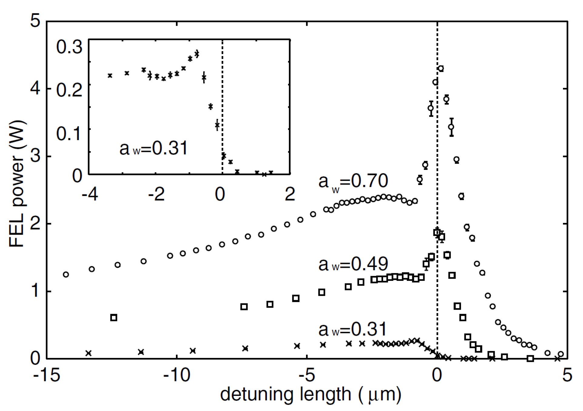
Figure 3.
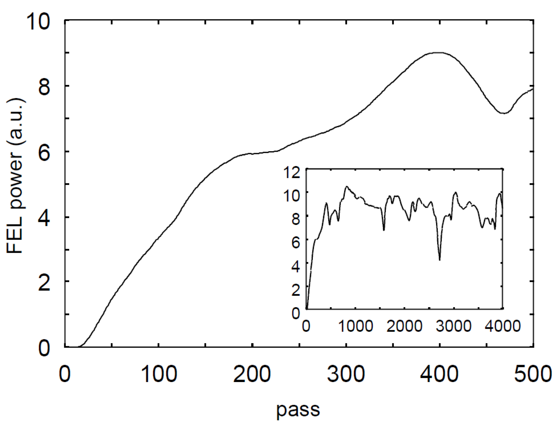
Numerical result for the JAERI-FEL start up simulation. Evolution of an FEL macropulse calculated with the JAERI-FEL parameters at lasing is plotted. Whole structure of macropulse is also shown in the inset [13].
Figure 3.
Numerical result for the JAERI-FEL start up simulation. Evolution of an FEL macropulse calculated with the JAERI-FEL parameters at lasing is plotted. Whole structure of macropulse is also shown in the inset [13].

Figure 4.
Evolution of an FEL pulse calculated with the JAERI-FEL parameters at lasing: (Left) 100th to 200th round trips; and (Right) 4000th round trip [13].
Figure 4.
Evolution of an FEL pulse calculated with the JAERI-FEL parameters at lasing: (Left) 100th to 200th round trips; and (Right) 4000th round trip [13].
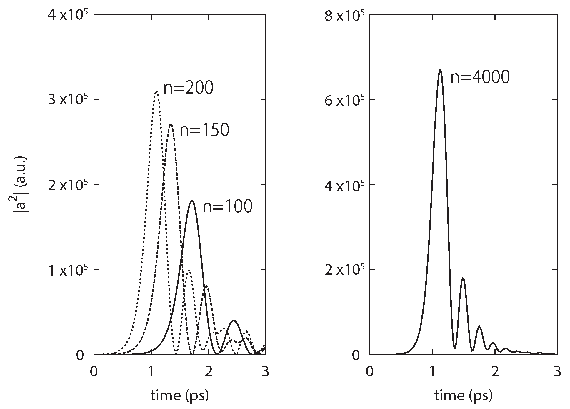
Figure 5.
Result of autocorrelation measurement with fringe-resolved SHG signal at the JAERI-FEL (dots). The solid line is a fitted curve by the chirped-sech pulse [14].
Figure 5.
Result of autocorrelation measurement with fringe-resolved SHG signal at the JAERI-FEL (dots). The solid line is a fitted curve by the chirped-sech pulse [14].
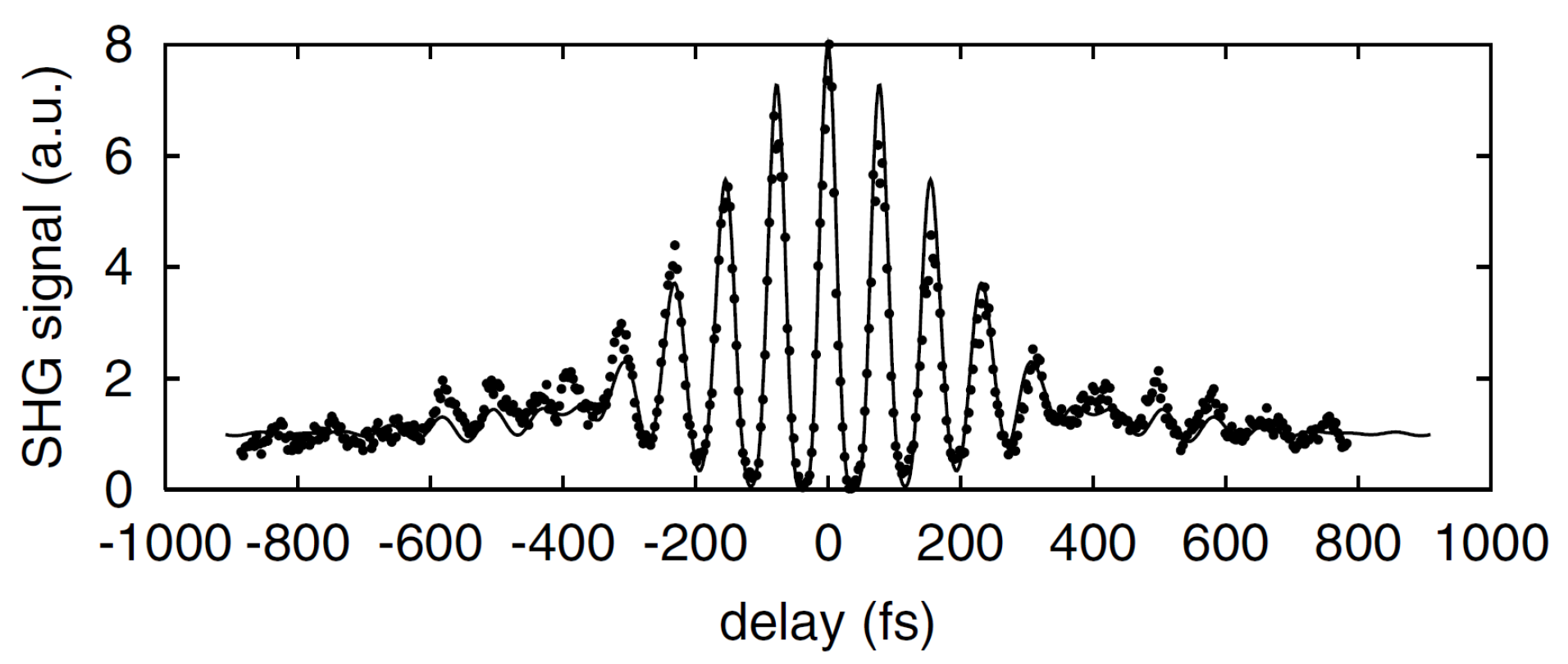
Figure 6.
Evolution of the energy distribution of the spent electron beam at KU-FEL. (a) Experimental result with FEL lasing for the best DCD parameter. (b) Numerical result with the DCD parameter of 9.4 m. The arrow indicates the timing of the cavity detuning condition altering from to 0 m [26].
Figure 6.
Evolution of the energy distribution of the spent electron beam at KU-FEL. (a) Experimental result with FEL lasing for the best DCD parameter. (b) Numerical result with the DCD parameter of 9.4 m. The arrow indicates the timing of the cavity detuning condition altering from to 0 m [26].
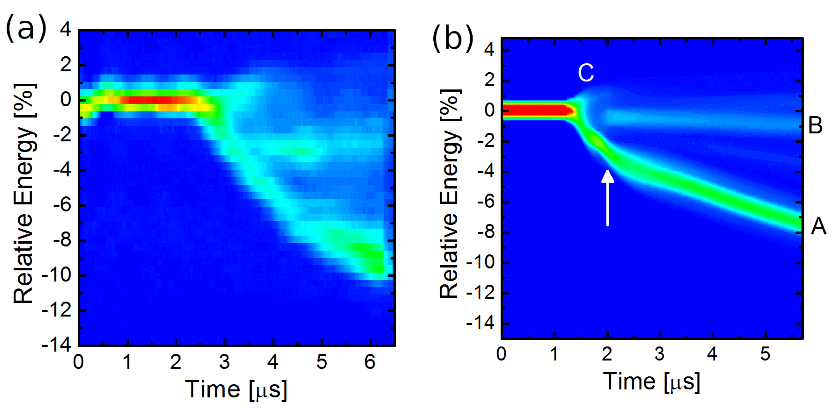
Figure 7.
Simulation results for KU-FEL. Evolution of the energy of electrons with different initial phases in the undulator at the end of the macropulse is plotted: (a–d) phase space plots of the two-wavelength slices of the electron beam at the center of the electron bunch and at the different longitudinal positions in undulator. The longitudinal position in the undulator for (a–d) are 0, 0.6, 1.2, and 1.7 m, respectively. The horizontal axis is relative position in the electron bunch normalized by the lasing wavelength m [26].
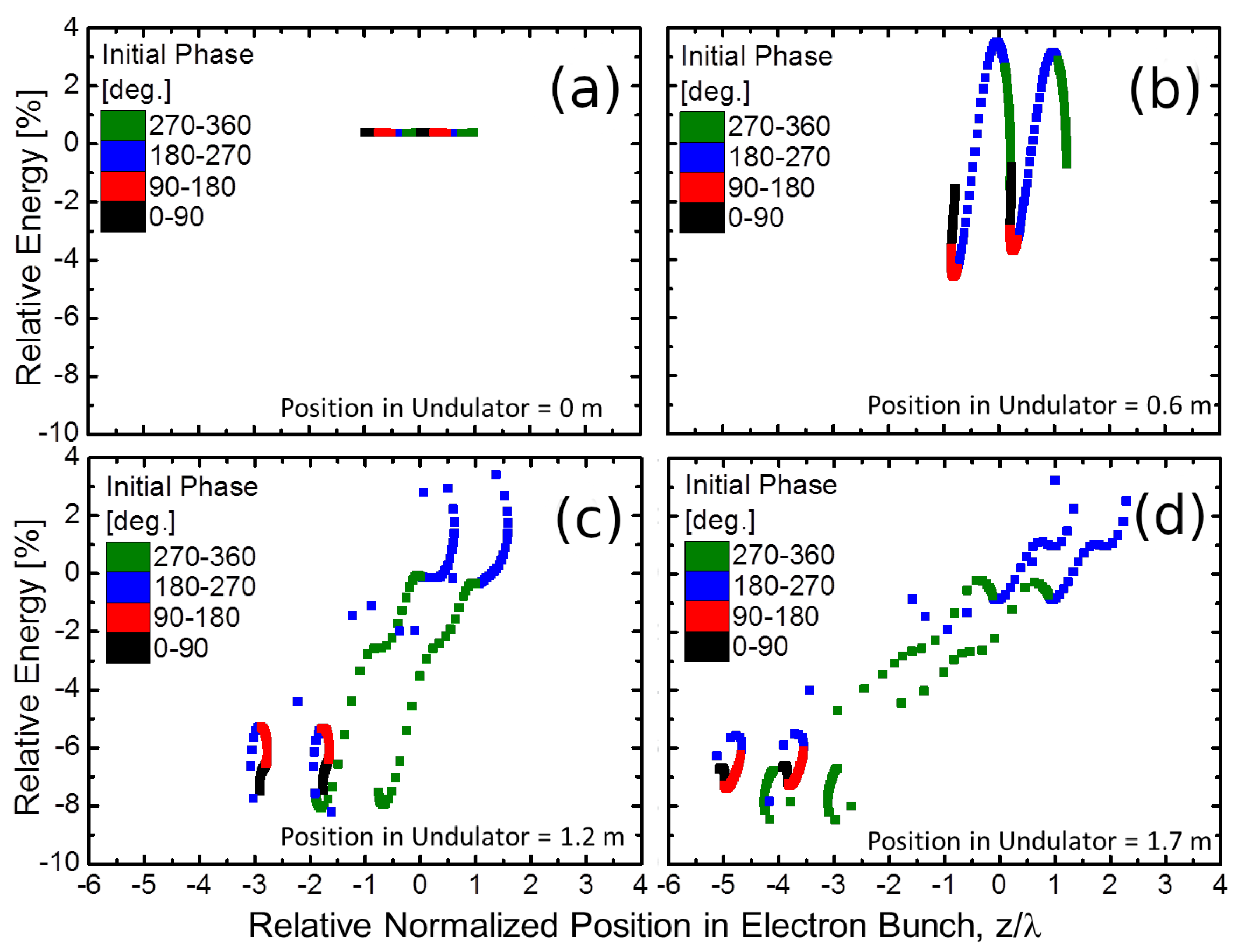
Figure 8.
Simulation results of FEL efficiency for the lasing at varying the number of undulator periods, , the bunch length and slippage distance, , and the normalized cavity loss . The normalized extraction efficiency, , is plotted as a function of the normalized cavity loss . Experimental results at the JAERI-FEL are also plotted.

Figure 9.
Cavity-length detuning curve calculated for the JAERI-FEL experiment with two different noise-factor: shot noise determined by the standard formula (solid line) and of that (dashed line) [12].
Figure 9.
Cavity-length detuning curve calculated for the JAERI-FEL experiment with two different noise-factor: shot noise determined by the standard formula (solid line) and of that (dashed line) [12].

Figure 10.
Temporal shapes of FEL pulses in a perfectly synchronized optical cavity simulated by one-dimensional code. Profile of the electron bunch at the entrance, , and the exit, , of the undulator is also plotted. The inset is the same FEL pulses plotted with a linear scale [39].
Figure 10.
Temporal shapes of FEL pulses in a perfectly synchronized optical cavity simulated by one-dimensional code. Profile of the electron bunch at the entrance, , and the exit, , of the undulator is also plotted. The inset is the same FEL pulses plotted with a linear scale [39].

Figure 11.
Temporal shapes of FEL pulses in a perfectly synchronized optical cavity with an external seed laser after 1500, 2000, and 2500 round trips simulated by one-dimensional code [39].
Figure 11.
Temporal shapes of FEL pulses in a perfectly synchronized optical cavity with an external seed laser after 1500, 2000, and 2500 round trips simulated by one-dimensional code [39].

Figure 12.
Contour plots of instantaneous phase of simulated FEL pulses in units of rad for: (a) without injection seeding; and (b) with injection seeding. Contour plots of instantaneous intensity of FEL pulses normalized to the maximum intensity for: (c) without injection seeding; and (d) with injection seeding [39].

Figure 13.
Schematic view of high-harmonics generation driven by an infrared FEL oscillator (FEL-HHG).
Figure 13.
Schematic view of high-harmonics generation driven by an infrared FEL oscillator (FEL-HHG).

Table 1.
Parameters for the JAERI-FEL experiment and simulation presented in Figure 10 and Figure 11.
| JAERI-FEL | This Study | |
|---|---|---|
| Electron beam | ||
| energy (MeV) | 16.5 | 50 |
| bunch charge (pC) | 510 | 100 |
| norm. emittance () | 40/22 | 12/12 |
| (mm-mrad) | ||
| bunch length (*) (ps) | 5 | 0.4 |
| peak current (A) | 200 | 250 |
| bunch repetition (MHz) | 10 | 10 |
| undulator | ||
| undulator parameter (rms) | 0.7 | 1.25 |
| pitch (cm) | 3.3 | 4.5 |
| number of periods | 52 | 40 |
| FEL | ||
| wavelength (m) | 22.3 | 6 |
| Rayleigh length (m) | 1.0 | 0.52 |
| FEL parameter, | 0.0044 | 0.0052 |
| cavity loss | 6% | 4% |
(*) The bunch length is FWHM of a triangular bunch for the JAERI-FEL and full width of a rectangular bunch for the simulations in the present study.
Table 2.
Example parameters of FEL oscillators for FEL-HHG.
| (A) | (B) | |
|---|---|---|
| Electron beam | ||
| energy (MeV) | 85 | 50 |
| bunch charge (pC) | 60 | 100 |
| norm. emittance () | 12/12 | 12/12 |
| (mm-mrad) | ||
| bunch length (ps) | 0.27 | 0.4 |
| peak current (A) | 220 | 250 |
| bunch repetition (MHz) | 10 | 10 |
| undulator | ||
| undulator parameter (rms) | 1.34 | 1.25 |
| pitch (cm) | 4.0 | 4.5 |
| number of periods | 80 | 40 |
| FEL | ||
| wavelength (m) | 2 | 6 |
| Rayleigh length (m) | 0.92 | 0.52 |
| FEL parameter, | 0.0030 | 0.0052 |
| cavity loss | 6% | 4% |
Publisher’s Note: MDPI stays neutral with regard to jurisdictional claims in published maps and institutional affiliations. |
© 2021 by the author. Licensee MDPI, Basel, Switzerland. This article is an open access article distributed under the terms and conditions of the Creative Commons Attribution (CC BY) license (http://creativecommons.org/licenses/by/4.0/).
Share and Cite
MDPI and ACS Style
Hajima, R. Few-Cycle Infrared Pulse Evolving in FEL Oscillators and Its Application to High-Harmonic Generation for Attosecond Ultraviolet and X-ray Pulses. Atoms 2021, 9, 15. https://0-doi-org.brum.beds.ac.uk/10.3390/atoms9010015
AMA Style
Hajima R. Few-Cycle Infrared Pulse Evolving in FEL Oscillators and Its Application to High-Harmonic Generation for Attosecond Ultraviolet and X-ray Pulses. Atoms. 2021; 9(1):15. https://0-doi-org.brum.beds.ac.uk/10.3390/atoms9010015
Chicago/Turabian StyleHajima, Ryoichi. 2021. "Few-Cycle Infrared Pulse Evolving in FEL Oscillators and Its Application to High-Harmonic Generation for Attosecond Ultraviolet and X-ray Pulses" Atoms 9, no. 1: 15. https://0-doi-org.brum.beds.ac.uk/10.3390/atoms9010015
Note that from the first issue of 2016, this journal uses article numbers instead of page numbers. See further details here.