
Circular Dichroism in the Photoionization of Unpolarized Atoms by Two Crossing Photon Beams


Physics Faculty, Voronezh State University, 394018 Voronezh, Russia
*
Author to whom correspondence should be addressed.
Atoms 2021, 9(4), 108; https://0-doi-org.brum.beds.ac.uk/10.3390/atoms9040108
Submission received: 11 November 2021
/
Revised: 29 November 2021
/
Accepted: 1 December 2021
/
Published: 3 December 2021
(This article belongs to the Special Issue A Tribute to Oleg Zatsarinny (1953–2021) and His Science–Fees Are Waived)
Abstract
:The polarization dependence of the photoionization probability was analyzed in the case when a randomly oriented atom is irradiated by two crossing polarized monochromatic photon beams with the same frequency. It was found that the angular distributions of photoelectrons exhibit the effect of circular dichroism (CD), which consists of the dependence of the photoionization probability on the sign of the circular polarization degree of each beam. We demonstrate that the CD effect exists only for coherent crossing photon beams. It was shown that CD effects are strongly dependent on the phase difference between the electric field vectors of the photon beams and have a quite large magnitude. The possibilities of the experimental observation of CD effects are discussed.
1. Introduction
CD effects manifest themselves as the dependence of the optical properties of media on the helicity of the photon beam (i.e., the sign of its circular polarization degree). It is a common knowledge that CD is absent in the single electron photoionization of randomly oriented atoms or molecules, which is due to the isotropy of such systems. So far, CD in a single photon ionization process has been observed in the two-electron ionization of unpolarized atoms [1,2,3,4,5,6,7,8]. In this case, CD is seen as the difference of angular distributions of electrons emitted in different directions, recorded for two opposite rotation directions of the electric field vectors. Note that the CD effect in the double photoionization vanishes when both electrons are emitted in opposite directions, since this situation is kinematically equivalent to the conventional single photoionization process. However, there is an exception [9] which takes place when the ionizing pulse is extremely short (i.e., broadband). In this case, the CD in the back-to-back emission of electrons is caused by the presence in the problem of a pseudoscalar carrier-envelope phase parameter.
Nevertheless, for a polarized initial bound state, CD effects do exist in a single electron atomic photoionization process [10,11,12,13,14,15,16] due to the anisotropy of polarized atomic targets. In molecular photoionization, CD effects can be observed in the angular distributions of electrons registered in the molecular coordinate frame [17,18,19]. From the general symmetry arguments, both the above situations are kinematically equivalent.
It is noteworthy that there are possibilities to observe CD in the atomic photoionization of unpolarized atoms. The first possibility is to use an axially asymmetric photon beam, e.g., the one with nonzero optical angular momentum [20]. Another possibility was pointed out in [21], where it was shown that the CD effect in the photoionization of randomly oriented atoms by a plane wave photon beam does occur when photoelectrons pass two slits before reaching the detector.
CD effects also emerge when an unpolarized atom is irradiated by a two-color () photon beam [22]. Similar CD effects in the ionization of helium atoms by biharmonic few-cycle pulses have been analyzed in a recent work [23]. In this case, the CD is caused by an interference of the ionization amplitudes corresponding to the single- and two-photon absorption channels. Apart from that, CD effects take place in the ionization of unpolarized atoms by an XUV pulse in the presence of an IR field [24,25]. From the general symmetry arguments, the reason for such CD effects to occur is that the axial symmetry of the system is disturbed by the presence of a pseudoscalar phase difference between the and components of the electromagnetic field.
Based on the first-order perturbation theory, in the present article, we demonstrate that CD effects can be observed in the angular distributions of electrons emitted by unpolarized atoms irradiated by two monochromatic photon beams of the same frequency crossing at the atomic target. Unlike the effect described in [22], this new CD effect is linear in the electric field amplitude of each beam, which means that the beam intensities need not be very large.
Since we have two photon beams, there are two kinds of CD effects to be distinguished. Namely, the first kind CD (CD1) is the difference of the ionization probability with respect to the simultaneous change of sign of the circular polarization degrees, , of both beams, . The CD of the second kind (CD2) is the difference of the probability with respect to the change of sign of the circular polarization (CP) degree of one of the beams (let it be the second pulse), . Clearly, when one of the pulses is linearly polarized (e.g., ), both effects, CD1 and CD2, coincide. We have found that the magnitude of CD effects strongly depends on the polarization of crossing beams and the relative phase of their electric field vectors. Those properties of CD in the photoionization by crossing beams make the above CD effects to be promising candidates for X-ray polarimetry.
The paper is organized as follows: In Section 2, we present the parametrization of the photoionization amplitude and probability in terms of scalar products of photon polarization vectors and the unit vector of photoelectron momentum . It is demonstrated in Section 2 that the photoionization probability can be factorized into a product of a dynamical part, independent of the polarization properties of the photon beams, and the geometrical (or kinematical) part, which determines the polarization and angular dependence of the probability. Remarkably, the geometrical part of the probability is the same for any atomic target as long as the initial bound state has zero angular momentum (i.e., an S-state). The parametrizations derived in Section 2 are valid for an arbitrary angle between the ionizing beams. Next, in Section 3, we consider in detail the CD effects in the ionization by two purely CP beams for the case of orthogonal beams; see Figure 1a. In Section 4, the angular distributions of photoelectrons in the ionization by orthogonal circularly and linearly polarized (LP) beams are analyzed. The conclusions (Section 5) contain a brief summary of the derived results and an outline for the future research. Atomic units are used throughout the text.
2. Parametrizations of the Photoionization Amplitude and Probability
For an atom located at the origin of the coordinate frame, the electric field strength acting on atomic electrons within the dipole approximation can be written as
where and are the amplitude and the complex polarization vector of the j-th photon beam, , and is the relative phase of the two beams.
It is convenient to use the following parametrization of the polarization vectors (below we omit subscript indices “1,2”):
where is the ellipticity parameter and is the unit vector along the major axis of the polarization ellipse of the photon beam propagating along the unit vector . For right (left) rotation of the electric field, we have (). Note that for a right-hand CP field, while for a left-hand circularly polarized field, and for a linearly polarized (LP) field polarized along the axis. The circular and linear polarization degrees are denoted as and ℓ, respectively, and are defined by
Within the first-order perturbation theory, the photoionization amplitude is defined by the matrix element
where is the final state of the emitted electron + residual ion, is the initial bound state, is the electric field strength, and is the dipole momentum operator.
For an initial S-state, the photoionization amplitude (4) can be written as
where is the dynamical parameter that depends on the photon energy and photoelectron momentum p but not on the polarization properties of light as well as the ionization geometry.
The conventional (i.e., single beam) photoionization process is characterized by the differential cross section, which is the probability per time unit related to the incoming photon flux. In our case, however, there are two photon beams coming from different directions. Therefore, below we describe the ionization process by the (doubly differential) probability (DP) per unit of time and element of the solid angle of an escaping electron [26]:
As can be seen, the angular dependence of the DP is not affected by the magnitude of the dynamical parameter , and it remains the same for any atomic or molecular target. Consequently, below we only analyze the polarization-angular part of the DP defined by
The first two terms on the right-hand side of this equation are, in fact, the sum of probabilities corresponding to the absorption of a single photon either from the first or the second photon beam. Each of those terms depends only on the LP degree of the corresponding photon beam. Indeed, taking into account (2) and (3), we obtain
The third term on the right-hand side of (7) is caused by the interference of the two channels of the ionization process, which leads to the occurrence of CD effects. For noncoherent beams, their relative phase varies in time randomly, and the Equation (7) should be averaged over . Since an average of the function is zero, we conclude that CD effects vanish in the photoionization by noncoherent photon beams. For coherent beams, the phase is stable in time and two kinds of CD effects take place. These effects are similar to CD effects in the scattering of X-ray photons by randomly oriented atoms [27]. As was mentioned above, CD of the first kind (CD1) is the difference of the DP with respect to the simultaneous change of the helicity of both photon beams (i.e., right-hand CP becomes left-hand CP, and vice versa). The absolute magnitude of the CD1 effect is defined by the angular parameter
where is the angular part of the DP for the photon beams with the CP degrees and . Noting that, according to (3), the replacement is equivalent to the replacement , we obtain from (9), (7),
Thus, the CD1 occurs when both beams are circularly (or elliptically) polarized and their relative phase is not equal to , .
The CD of the second kind (CD2) consists of the difference of the DP with respect to the change of the helicity of one of the photon beams (let it be the first one). Accordingly, the CD2 is determined by the angular parameter
which, noting Equation (7), writes
From (11) and this equation, it is seen that CD2 is absent for the LP first beam (). When the second beam is polarized linearly, , the CD2 parameter (12) becomes
where is the unit polarization vector of the LP beam. Remarkably, in this case, the CD2 parameter is proportional to the same phase factor as in the CD1. Thus, both CD1 and CD2 (the latter only for EP + LP beams) effects are maximal when the phase shift, , between the electric fields of the two beams is equal to . If the photon beams are obtained by means of the beam splitting technique, the condition demands the optical path difference to comprise an odd number of half-waves (i.e., ). By contrast, if the optical path difference is equal to an integer number of wavelengths (), then and CD effects vanish (except the CD2 effect for an elliptically polarized second beam, ).
Note that the above Equations (5)–(13) are valid for beams crossing at an arbitrary angle. For the sake of simplicity, below we analyze only the situation when two photon beams propagate in perpendicular directions and have the same intensity, so that (). We do not consider the general case of elliptically polarized photon beams since it leads to rather cumbersome expressions, especially when major axes of polarization ellipses are tilted with respect to the propagation plane of the photons (i.e., to the z-axis in Figure 1).
Another problem is that the relative phase between two electric fields depends on the position of atoms in space. Since atoms are placed in space randomly, one has to average the DP (6) over the phase . Clearly, this cancels out the interference term in (7) and, hence, the CD effects. To overcome this difficulty, we propose to follow the procedure described in [28]. Namely, for crossing photon beams with planar wavefronts, one can choose the plane at their intersection in such a way that the relative phase of the crossing waves would be the same in each point in this plane. For example, for two plane waves propagating along the orthogonal x and y axes (see Figure 1), the relative phase is zero for points located in a plane tilted at an angle 45 with respect to the x or y axis (it is the plane in Figure 1). Thus, the relative phase of the ionizing photon beams is the same for atoms located in that plane. Indeed, in the plane, one has , and the spatial part of the relative phase is zero, , where k is the wavenumber. Therefore, below we analyze only the angular distributions of electrons emitted in the plane. For electrons emitted in the plane, the projections of the unit vector of the photoelectron momentum on the axes of the coordinate frame have the form
Note that hereafter is the polar angle of the vector in the detection -plane, which varies from 0 to ; see Figure 1a.
3. CD Effects for CP Beams
For purely circularly polarized beams, we have , and according to the Figure 1, the polarization vectors can be written as combinations of unit Cartesian basis vectors:
This expression and Equation (8) allow us to rewrite the DP in terms of the polar angle ,
Inserting Equation (16) into the general Equation (10) defining the absolute magnitude of the CD1 effect, we obtain:
It is seen that the CD1 vanishes for the phase shift equal to an integer number of (i.e., the optical path difference of the beams is an integer number of waves) or for oppositely polarized CP beams, i.e., for .
Now, let us turn to the analysis of the CD2 effect defined by (12). For the detection geometry shown in Figure 1, the photon polarization vectors have the form (15), and the components of the unit electron momentum vector are given by (14). As a result, the general expression (12) for the CD parameter reduces to
From this parametrization, it follows that CD2 cannot be completely suppressed neither by varying the phase shift nor by changing the rotation direction of the electric field of the CP beam (i.e., by changing the sign of ). This is in contrast with the CD1 effect, which vanishes for .
Interestingly, for corresponding to the minima or maxima of the field intensity, , the CD1 parameter is zero, and only the CD2 effect is present. Indeed, for CP + CP beams with equal intensities (), according to Equations (1) and (15), we have
The interference minima/maxima of I correspond to , when and the CD1 parameter (18) are zero, while . It is also noteworthy that for CP + CP beams the field intensity I does not depend on the pulse helicities.
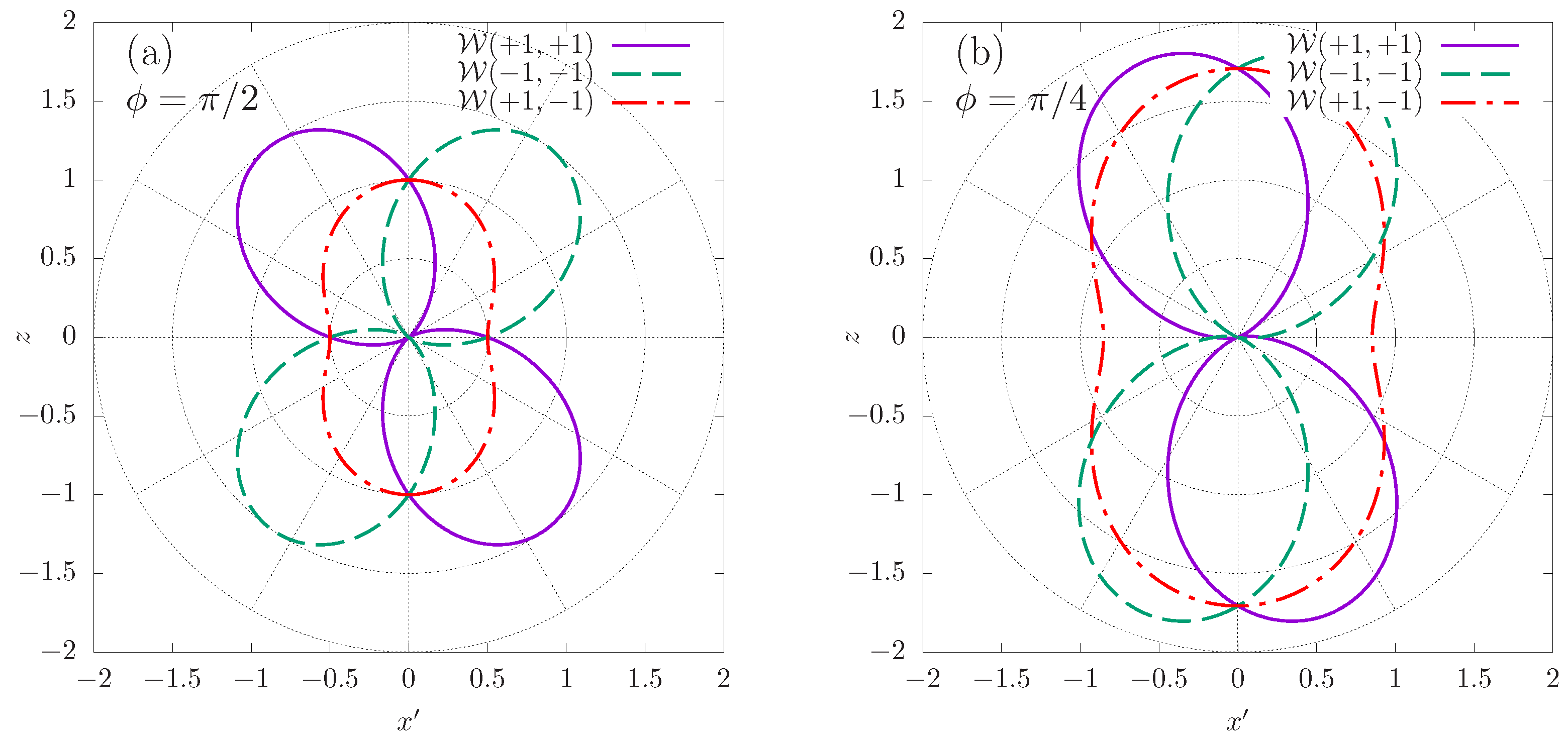
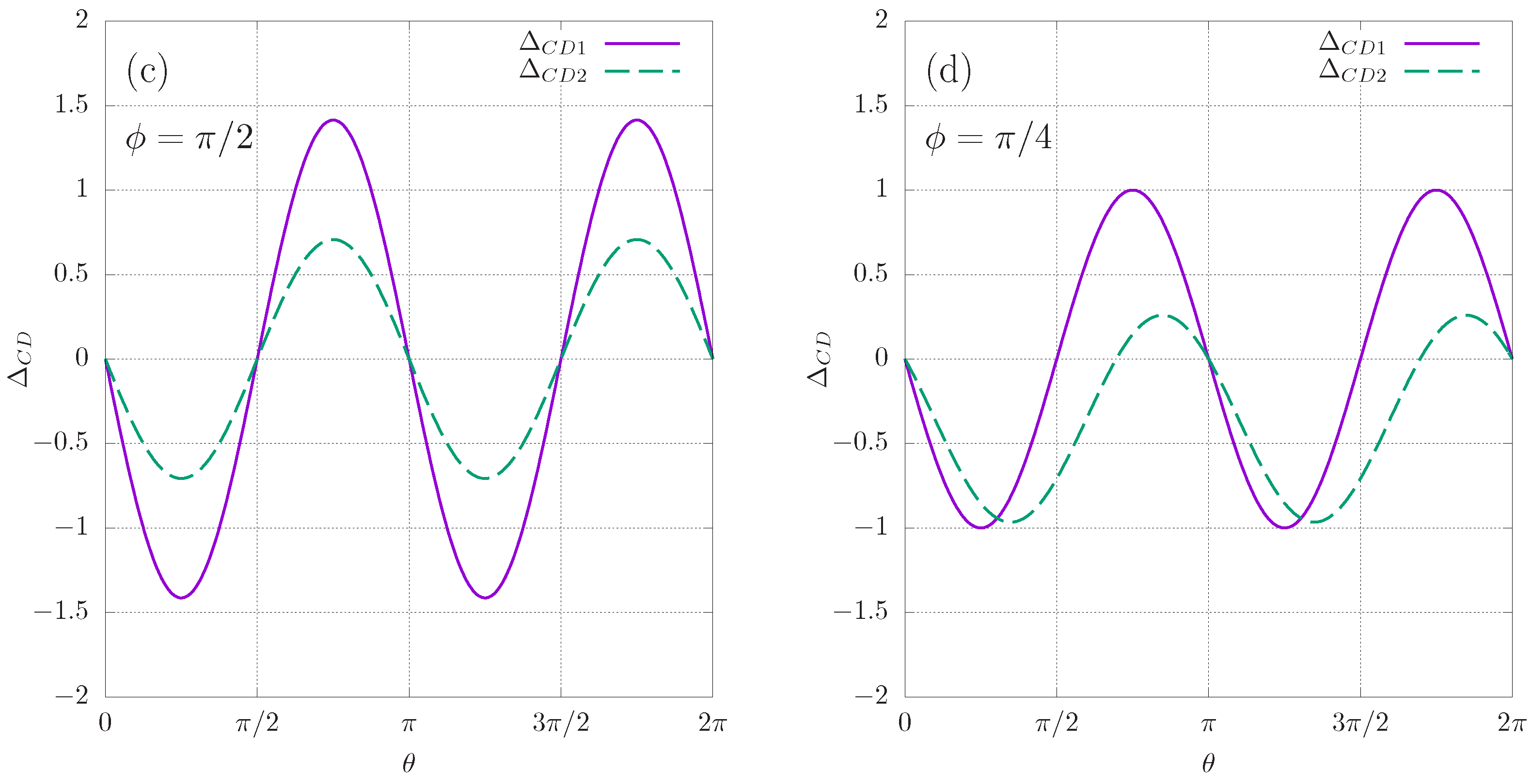
In Figure 2, we show the magnitudes of the geometric DP and CD parameters and for two values of the relative phase, and . As can be seen in Figure 2a,b, the shape of the DP polar diagrams for remains essentially the same for different values of the relative phase , while their tilt angle with respect to the z-axis varies noticeably. Another observation is that the CD1 parameter has the same angular dependence for and with only its amplitude changing; see Figure 2c,d. It is also seen in Figure 2c that for , CD1 and CD2 parameters have the same angular dependence. This is the consequence of expressions (19) and (18) for CD parameters. Indeed, for we have ; therefore, the second term on the right-hand side of (19) vanishes, and both and become proportional to .
4. CD Effects for CP + LP Beams
For CP and LP beams, we have and . According to the definitions (9), (11), in this case, both CD2 and CD1 parameters are the same, and the magnitude of this CD effect is defined by (13).
The beam propagation directions are shown in Figure 1a, but the second beam is now LP, and its real unit polarization vector lies in the plane. As above, the photon polarization vector of the first CP beam is defined by (15), and we consider only the situation when electrons are emitted in the plane (see Figure 1), so that the components of are given by (14). Consequently, the general Equation (13) defining the CD parameter becomes
Similarly to the CD1 effect for CP + CP beams, the magnitude of is determined by the phase factor .
For the ionization by CP + LP beams, an expression for the geometric part of the DP can be derived from the general Equation (7) noting Equations (14) and (15) for and ,
It is instructive to write the field intensity I for CP + LP beams ( below):
We note that, when the angle between polarization planes of CP and LP beams is equal to 0 or , the field intensity is independent of . Namely, for perpendicular polarization planes, we have and , which yields , i.e., the intensity is independent of the phase . For parallel polarization planes, (see Figure 1a), and Equation (23) becomes
which is similar to the Equation (20) for CP + CP fields. When the angle between polarization planes of CP and LP beams is neither 0, nor , the field intensity does depend on the helicity of the CP beam. This is in contrast to the case of CP + CP beams when I is independent of , .
In Figure 3a,b, we present results for the DP parameter for two values of the phase difference: (Figure 3a) and (Figure 3b). In both figures, parameters are shown for two polarizations of the LP beam as indicated by the index z or x in the figure legend: (i) “z” means that the polarization vector of the LP beam lies in the polarization plane of the CP beam, (see Figure 1), and (ii) “x” means , i.e., the LP beam is polarized along the propagation direction of the CP beam. One observes that, when the polarization planes of the LP and CP beams are perpendicular (case (i)), the angular distributions are substantially different for different helicities of the CP beam. By contrast, in case (ii), when the polarization planes of the CP and LP beams are parallel, the angular distributions for have the same shape and are only slightly rotated with respect to each other.
The geometric CD factors are shown in Figure 3c,d as functions of the polar angle for the same parameters of the photon beams as in Figure 3a,b. It is seen that maxima and minima of coincide for both cases (i) and (ii). In Figure 3c, the dash-dotted curve “, zx” shows the parameter corresponding to the LP beam whose polarization plane is tilted at an angle of with respect to the polarization plane of the CP beam, which is the plane in Figure 1. (In this case, the polarization vector of the LP beam is .) Figure 3 demonstrates high sensitivity of the magnitude and angular dependence of the CD effect to the orientation of the polarization plane of the LP beam as well as to the phase between the two beams.
5. Conclusions
We analyzed the polarization dependence of the photoionization probabilities for the ionization of randomly oriented atoms by a pair of orthogonally propagating, monochromatic polarized photon beams. Our consideration was based on the first-order perturbation theory in the photon–atom interaction and is valid for any atom or ion ionized from a bound S-state. It was demonstrated that, if at least one of the beams is circularly polarized, the ionization probability exhibits a significant CD effect, i.e., a pronounced asymmetry with respect to the change of the CP degree of that beam (see Figure 2 and Figure 3). For two CP beams, the DP has an asymmetry with respect to the change of helicities of both beams (the CD1 effect, see Section 3) or one of the beams (the CD2 effect, see Section 4). These effects are caused by the interference of the two channels of the ionization process, which correspond to the absorption of a photon from either the first or the second beam. Of course, this interference exists only for coherent beams, i.e., beams having their relative phase stable in time. In optics, the interference of two coherent light beams is determined by . Similarly, in the case of the ionization by two coherent beams, the interference effects (such as CD) depend on . Namely, for CP + CP beams, the CD1 effect is proportional to ; see Equation (18). The same holds true for the CD effect in the ionization by CP + LP beams; see Equation (21). It is interesting that, unlike the CD1 effect, the CD2 effect in the ionization by CP + CP beams cannot be completely eliminated by varying .
In Section 3 and Section 4, we limited our consideration to beams with equal intensities. The key result of Section 2, which is the general parametrization (7) of the DP, is valid in the general case of arbitrary relative intensities and polarizations of photon beams. Therefore, the results of our analysis of CD effects, presented in Section 3 and Section 4, remain qualitatively valid in the case of beams with unequal intensities. In the presented paper, we have also assumed that the initial bound state of an atomic target has zero total angular momentum. However, our treatment can be easily generalized to the case of bound states with nonzero angular momentum. This can be performed by using the technique described in [15], where it was shown that for bound states with nonzero angular momentum no new polarization effects occur in angular distributions as long as an atom is unpolarized. The only difference is in the occurrence of an additional term in the DP (7), which is independent of the emission directions of the photoelectron. Thus, the magnitude of the DP is determined by two dynamical parameters, as in the case of the conventional single-beam photoionization [15]. However, the angular structure of the interference term of the DP remains the same, and only the relative magnitude of the CD effects is affected. Note that the values of the two dynamical parameters of the DP can be extracted from the calculations of the conventional photoeffect cross sections [29]. The above-described high sensitivity of angular distributions of photoelectrons to the parameters of ionizing beams can be utilized for the analysis of polarization properties of crossing monochromatic beams. We remark that detectors of angular distributions of electrons in atomic photoionization are employed in polarimeters for XUV and X-ray radiation at FEL [30,31,32,33].
In Section 3 and Section 4, we analyzed only CD effects in the angular distributions of electrons emitted in the plane shown in Figure 1. The reason was that for atoms, located in that plane, the relative phase between plane wave photon beams is constant, independently of atom’s positions. Otherwise, for atoms in a gas, the relative phase would depend on the (random) positions of atoms and after the averaging of the DP over the interference effects (such as CD) cancel out. However, for atoms in an optical lattice [34,35,36], the relative phase would vary in a regular way, and interference effects in the ionization by crossing beams, in principle, should be present for any detection geometry. This fact could be used for both to achieve and control a selective ionization (or excitation) of atoms trapped in an optical lattice. This, however, would require a thorough analysis because of the large amount of possibilities of the experimental setup. The DP of the process depends not only on the orientation of the beam’s propagation plane with respect to the lattice plane but also on the spacing of atoms. Apart from that, the single photon ionization requires coherent UV sources, which would be problematic in the experiments with the optical lattices. In this case, it would be more practical to consider multiphoton + ionization by crossing photon beams, provided that m and n are integer numbers and the beam’s phases are synchronized. This topic is the subject of a forthcoming research.
Author Contributions
A.V.M. and N.L.M. contributed to the calculation of results presented and to the writing of the text. All authors have read and agreed to the published version of the manuscript.
Funding
This research was funded by the Ministry of Science and Higher Education of Russia through Project No. FZGU-2020-0035 and under Agreement No. 075-15-2021-1351 in part of CD effects for CP + LP photon beams (N.L.M.)
Institutional Review Board Statement
Not applicable.
Informed Consent Statement
Not applicable.
Data Availability Statement
Not applicable.
Conflicts of Interest
The authors declare no conflict of interest.
Abbreviations
The following abbreviations are used in this manuscript:
| CD | Circular dichroism |
| CD1 | Circular dichroism of the first kind |
| CD2 | Circular dichroism of the second kind |
| CP | Circular polarization |
| DP | Differential probability |
| LP | Linear polarization |
References
- Berakdar, J.; Klar, H. Circular dichroism in double photoionization. Phys. Rev. Lett. 1992, 69, 1175–1177. [Google Scholar] [CrossRef] [PubMed]
- Viefhaus, J.; Avaldi, L.; Snell, G.; Wiedenhöft, M.; Hentges, R.; Rüdel, A.; Schäfers, F.; Menke, D.; Heinzmann, U.; Engelns, A.; et al. Experimental Evidence for Circular Dichroism in the Double Photoionization of Helium. Phys. Rev. Lett. 1996, 77, 3975–3978. [Google Scholar] [CrossRef] [PubMed]
- Kheifets, A.S.; Bray, I. Calculation of Circular Dichroism in Helium Double Photoionization. Phys. Rev. Lett. 1998, 81, 4588–4591. [Google Scholar] [CrossRef]
- Maulbetsch, F.; Briggs, J.S. Angular distribution of electrons following double photoionization. J. Phys. B 1993, 26, 1679–1696. [Google Scholar] [CrossRef]
- Mergel, V.; Achler, M.; Dörner, R.; Khayyat, K.; Kambara, T.; Awaya, Y.; Zoran, V.; Nyström, B.; Spielberger, L.; McGuire, J.H.; et al. Helicity Dependence of the Photon-Induced Three-Body Coulomb Fragmentation of Helium Investigated by Cold Target Recoil Ion Momentum Spectroscopy. Phys. Rev. Lett. 1998, 80, 5301–5304. [Google Scholar] [CrossRef] [Green Version]
- Kheifets, A.; Bray, I.; Soejima, K.; Danjo, A.; Okuno, K.; Yagishita, A. Experimental and theoretical study of linear and circular dichroism in helium double photoionization. J. Phys. B 1999, 32, L501–L509. [Google Scholar] [CrossRef]
- Soejima, K.; Danjo, A.; Okuno, K.; Yagishita, A. Linear and Circular Dichroism in the Double Photoionization of Helium. Phys. Rev. Lett. 1999, 83, 1546–1549. [Google Scholar] [CrossRef]
- Briggs, J.S.; Schmidt, V. Differential cross sections for photo-double-ionization of the helium atom. J. Phys. B 2000, 33, R1–R48. [Google Scholar] [CrossRef]
- Ngoko Djiokap, J.M.; Manakov, N.L.; Meremianin, A.V.; Starace, A.F. Carrier-envelope-phase-induced asymmetries in double ionization of helium by an intense few-cycle XUV pulse. Phys. Rev. A 2013, 88, 053411. [Google Scholar] [CrossRef] [Green Version]
- Cherepkov, N.A.; Kuznetsov, V.V. Optical activity of polarised atoms. J. Phys. B 1989, 22, L405–L409. [Google Scholar] [CrossRef]
- Cherepkov, N.; Chernysheva, L.; Kuznetsov, V.; Semenov, S. Photoionization of polarized excited Li atoms. J. Electron Spectrosc. Relat. Phenom. 1996, 79, 275–278. [Google Scholar] [CrossRef]
- Grum-Grzhimailo, A.N.; Gryzlova, E.V.; Cubaynes, D.; Heinecke, E.; Yalçinkaya, M.; Zimmermann, P.; Meyer, M. The generalized geometrical model for the photoionization of polarized atoms: Application to linear dichroism in the 2p photoemission from Na 32S and Na* 32P initial states. J. Phys. B 2009, 42, 171002. [Google Scholar] [CrossRef]
- Baier, S.; Grum-Grzhimailo, A.N.; Kabachnik, N.M. Angular distribution of photoelectrons in resonant photoionization of polarized atoms. J. Phys. B 1994, 27, 3363–3388. [Google Scholar] [CrossRef]
- Grum-Grzhimailo, A.N. Non-dipole effects in magnetic dichroism in atomic photoionization. J. Phys. B 2001, 34, L359–L365. [Google Scholar] [CrossRef]
- Manakov, N.L.; Marmo, S.I.; Meremianin, A.V. A new technique in the theory of angular distributions in atomic processes: The angular distribution of photoelectrons in single and double photoionization. J. Phys. B 1996, 29, 2711–2737. [Google Scholar] [CrossRef]
- Klimova, Y.; Marmo, S.; Meremianin, A. Angular distribution of electrons in multiphoton ionisation of polarised Lithium atoms. Phys. Lett. A 2013, 377, 1439–1443. [Google Scholar] [CrossRef]
- Cherepkov, N.A.; Kuznetsov, V.V. Photoionization of oriented molecules. Z. Phys. D 1987, 7, 271–280. [Google Scholar] [CrossRef]
- Suzuki, Y.I. Circular dichroism in photoionization of degenerate orbitals: Spin-polarized photoelectrons and spontaneous separation of oriented photoions. J. Chem. Phys. 2018, 149, 204312. [Google Scholar] [CrossRef]
- Fehre, K.; Novikovskiy, N.M.; Grundmann, S.; Kastirke, G.; Eckart, S.; Trinter, F.; Rist, J.; Hartung, A.; Trabert, D.; Janke, C.; et al. Fourfold Differential Photoelectron Circular Dichroism. Phys. Rev. Lett. 2021, 127, 103201. [Google Scholar] [CrossRef]
- De Ninno, G.; Wätzel, J.; Ribič, P.R.; Allaria, E.; Coreno, M.; Danailov, M.B.; David, C.; Demidovich, A.; Di Fraia, M.; Giannessi, L.; et al. Photoelectric effect with a twist. Nat. Photon. 2020, 14, 554–558. [Google Scholar] [CrossRef]
- Feagin, J.M. Circular Dichroism in Photo-Single-Ionization of Unoriented Atoms. Phys. Rev. Lett. 2002, 88, 043001. [Google Scholar] [CrossRef] [PubMed]
- Taïeb, R.; Véniard, V.; Maquet, A.; Manakov, N.L.; Marmo, S.I. Circular dichroism from unpolarized atoms in multiphoton multicolor ionization. Phys. Rev. A 2000, 62, 013402. [Google Scholar] [CrossRef]
- Volotka, A.V.; Hofbrucker, J.; Fritzsche, S. Steering of circular dichroism in biharmonic ionization of atoms. Phys. Rev. A 2021, 104, L031103. [Google Scholar] [CrossRef]
- Mazza, T.; Ilchen, M.; Rafipoor, A.; Callegari, C.; Finetti, P.; Plekan, O.; Prince, K.; Richter, R.; Demidovich, A.; Grazioli, C.; et al. Angular distribution and circular dichroism in the two-colour XUV+NIR above-threshold ionization of helium. J. Mod. Opt. 2016, 63, 367–382. [Google Scholar] [CrossRef]
- Kazansky, A.K.; Grigorieva, A.V.; Kabachnik, N.M. Circular Dichroism in Laser-Assisted Short-Pulse Photoionization. Phys. Rev. Lett. 2011, 107, 253002. [Google Scholar] [CrossRef]
- Berestetskii, V.B.; Lifshitz, E.M.; Pitaevskii, L.P. Quantum Electrodynamics; Pergamon Press: Oxford, UK, 1982. [Google Scholar]
- Manakov, N.L.; Meremianin, A.V.; Maquet, A.; Carney, J.P.J. Photon-polarization effects and their angular dependence in relativistic two-photon bound-bound transitions. J. Phys. B 2000, 33, 4425–4446. [Google Scholar] [CrossRef]
- Ngoko Djiokap, J.M.; Meremianin, A.V.; Manakov, N.L. Electron interference in atomic ionization by two crossing polarized ultrashort pulses. Phys. Rev. A 2021, 103, 023103. [Google Scholar] [CrossRef]
- Zatsarinny, O. BSR: B-spline atomic R-matrix codes. Comp. Phys. Commun. 2006, 174, 273–356. [Google Scholar] [CrossRef]
- Richter, M.; Gottwald, A.; Kroth, U.; Sorokin, A.A.; Bobashev, S.V.; Shmaenok, L.A.; Feldhaus, J.; Gerth, C.; Steeg, B.; Tiedtke, K.; et al. Measurement of gigawatt radiation pulses from a vacuum and extreme ultraviolet free-electron laser. Appl. Phys. Lett. 2003, 83, 2970–2972. [Google Scholar] [CrossRef]
- Kato, M.; Tanaka, T.; Kurosawa, T.; Saito, N.; Richter, M.; Sorokin, A.A.; Tiedtke, K.; Kudo, T.; Tono, K.; Yabashi, M.; et al. Pulse energy measurement at the hard x-ray laser in Japan. Appl. Phys. Lett. 2012, 101, 023503. [Google Scholar] [CrossRef]
- Chernov, V.E.; Dorofeev, D.L.; Elfimov, S.V.; Zon, B.A.; Gavrilov, G.E.; Naryshkin, Y.G. Pseudopotential calculations of photoionization of atoms in the x-ray photon energy range and FEL beam monitor development. Laser Phys. Lett. 2015, 12, 036002. [Google Scholar] [CrossRef]
- Merem’yanin, A.V.; Chernov, V.E.; Gavrilov, G.E.; Naryshkin, Y.G.; Zon, B.A. Quadrupole effects in angular distributions of photoelectrons upon ionization of Kr by X-ray photons. Opt. Spectrosc. 2017, 122, 692–698. [Google Scholar] [CrossRef]
- Hachisu, H.; Miyagishi, K.; Porsev, S.G.; Derevianko, A.; Ovsiannikov, V.D.; Pal’chikov, V.G.; Takamoto, M.; Katori, H. Trapping of Neutral Mercury Atoms and Prospects for Optical Lattice Clocks. Phys. Rev. Lett. 2008, 100, 053001. [Google Scholar] [CrossRef] [Green Version]
- Takamoto, M.; Hong, F.L.; Higashi, R.; Katori, H. An optical lattice clock. Nature 2005, 435, 321–324. [Google Scholar] [CrossRef]
- Katori, H. Optical lattice clocks and quantum metrology. Nat. Photonics 2011, 5, 203–210. [Google Scholar] [CrossRef]
Figure 1.
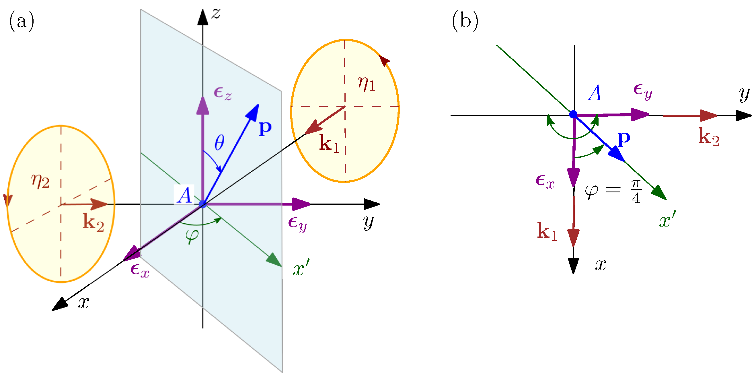
Ionization geometry. A is the atomic target, first and second photon beams propagate along the x- and y-axis, respectively. The z-axis is perpendicular to the beam propagation plane . Panel (b) is the top view of the geometry on panel (a). For atoms located in the plane, the phase shift between two beams is constant. is the polar angle of the photoelectron momentum vector in the detection -plane, .
Figure 1.
Ionization geometry. A is the atomic target, first and second photon beams propagate along the x- and y-axis, respectively. The z-axis is perpendicular to the beam propagation plane . Panel (b) is the top view of the geometry on panel (a). For atoms located in the plane, the phase shift between two beams is constant. is the polar angle of the photoelectron momentum vector in the detection -plane, .

Figure 2.
Magnitudes of angular parts of DP’s (7) and CD’s (9), (13) for the ionization by CP + CP beams and two values of their relative phase, and . Upper row: polar diagrams of the DP parameters for (panel (a)) and for (panel (b)). Lower row: CD parameters as functions of the polar angle (see Figure 1) for two values of the relative phase: in panel (c) and in panel (d).


Figure 3.
Magnitudes of geometric DP and CD parameters for the ionization by CP + LP beams and two values of their relative phase, and . (a,b): polar diagrams of the DP parameter . “z” indices to the right of and correspond to the parallel polarization planes of CP and LP beams, i.e., in Figure 1. “x” indices correspond to the perpendicular polarization planes of CP and LP beams, i.e., in Figure 1. (c,d): the CD parameters as functions of the polar angle (see Figure 1). In panel (c), the dash-dotted line (, zx) shows the parameter for the case of an LP beam whose polarization plane is tilted at an angle with respect to the polarization plane of the CP beam, .

Publisher’s Note: MDPI stays neutral with regard to jurisdictional claims in published maps and institutional affiliations. |
© 2021 by the authors. Licensee MDPI, Basel, Switzerland. This article is an open access article distributed under the terms and conditions of the Creative Commons Attribution (CC BY) license (https://creativecommons.org/licenses/by/4.0/).
Share and Cite
MDPI and ACS Style
Meremianin, A.V.; Manakov, N.L. Circular Dichroism in the Photoionization of Unpolarized Atoms by Two Crossing Photon Beams. Atoms 2021, 9, 108. https://0-doi-org.brum.beds.ac.uk/10.3390/atoms9040108
AMA Style
Meremianin AV, Manakov NL. Circular Dichroism in the Photoionization of Unpolarized Atoms by Two Crossing Photon Beams. Atoms. 2021; 9(4):108. https://0-doi-org.brum.beds.ac.uk/10.3390/atoms9040108
Chicago/Turabian StyleMeremianin, Alexei V., and Nikolai L. Manakov. 2021. "Circular Dichroism in the Photoionization of Unpolarized Atoms by Two Crossing Photon Beams" Atoms 9, no. 4: 108. https://0-doi-org.brum.beds.ac.uk/10.3390/atoms9040108
Note that from the first issue of 2016, this journal uses article numbers instead of page numbers. See further details here.