Balancing of the Orthoglide Taking into Account Its Varying Payload †


1
LS2N-Ecole Centrale de Nantes-UMR 6004, 1 rue de la Noë, BP 92101, F-44321 Nantes, France
2
INSA Rennes/Mecaproce, 20 Av. des Buttes de Coësmes, CS 70839, F-35708 Rennes, France
*
Author to whom correspondence should be addressed.
†
This paper is an extended version of our conference paper: Geng J., Arakelian V., Chablat D., Lemoine P. Shaking Force Balancing of the Orthoglide. In Proceedings of the 29th International Conference on Robotics in Alpe-Adria-Danube Region (RAAD 2020), Futuroscope-Poitiers, France, 17−19 June 2020.
‡
The authors contributed equally to this work.
Robotics 2021, 10(1), 30; https://0-doi-org.brum.beds.ac.uk/10.3390/robotics10010030
Submission received: 9 December 2020
/
Revised: 29 January 2021
/
Accepted: 3 February 2021
/
Published: 6 February 2021
(This article belongs to the Special Issue Advances in European Robotics)
Abstract
:For fast-moving robot systems, the fluctuating dynamic loads transmitted to the supporting frame can excite the base and cause noise, wear, and fatigue of mechanical components. By reducing the shaking force completely, the dynamic characteristics of the robot system can be improved. However, the complete inertial force and inertial moment balancing can only be achieved by adding extra counterweight and counter-rotation systems, which largely increase the total mass, overall size, and complexity of robots. In order to avoid these inconveniences, an approach based on the optimal motion control of the center of mass is applied for the shaking force balancing of the robot Orthoglide. The application of the “bang–bang” motion profile on the common center of mass allows a considerable reduction of the acceleration of the total mass center, which results in the reduction of the shaking force. With the proposed method, the shaking force balancing of the Orthoglide is carried out, taking into account the varying payload. Note that such a solution by purely mechanical methods is complex and practically inapplicable for industrial robots. The simulations in ADAMS software validate the efficiency of the suggested approach.
1. Introduction
It is known that a mechanical system with an unbalanced shaking force/moment transmits substantial vibration to the frame. Thus, a primary objective of the balancing is to cancel or reduce the variable dynamic loads transmitted to the frame and surrounding structures.
The methods of shaking force balancing can be arranged as follows:
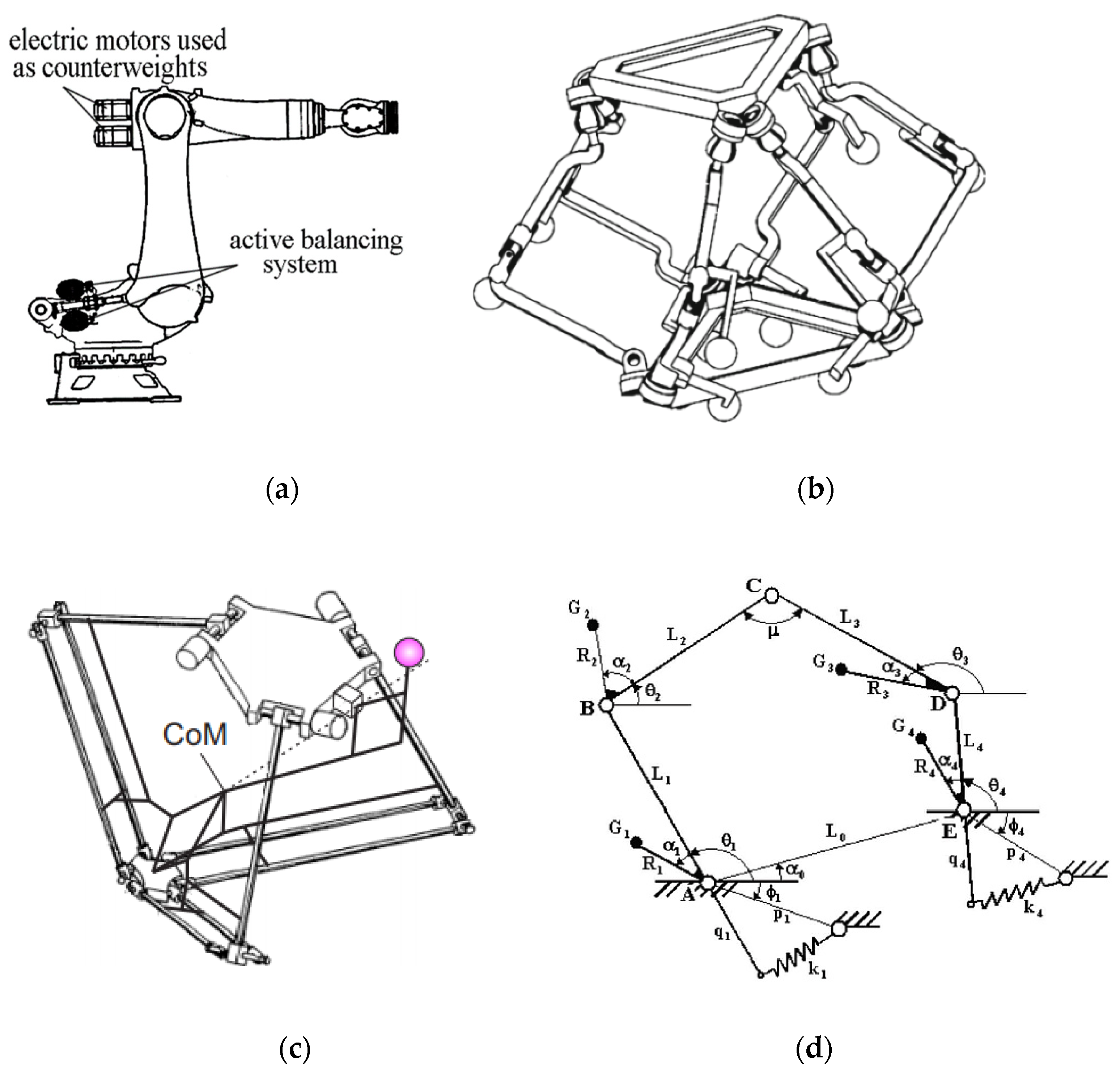
- By adding counterweight in order to keep the total mass center of moving links stationary [1]. It is obvious that the adding of the counterweights is not desirable because it leads to the increase of the total mass, of the overall size and of the efforts in joints. To avoid these drawbacks, the masses of the motors can be used as counterweights [2] (Figure 1a). Taking into account the complexity of the parallel manipulators, adding counterweights became not interesting, especially in spatial ones [3] (Figure 1b);
- By adding auxiliary structures. In [4,5,6], the parallelograms were used as auxiliary structures in order to create the balanced manipulators. In [7], the pantograph (Figure 1c) has been added in order to balance the shaking force of the Delta robot. Such a solution leads to a decrease in the added masses of counterweights, but the practical application remains a challenge;
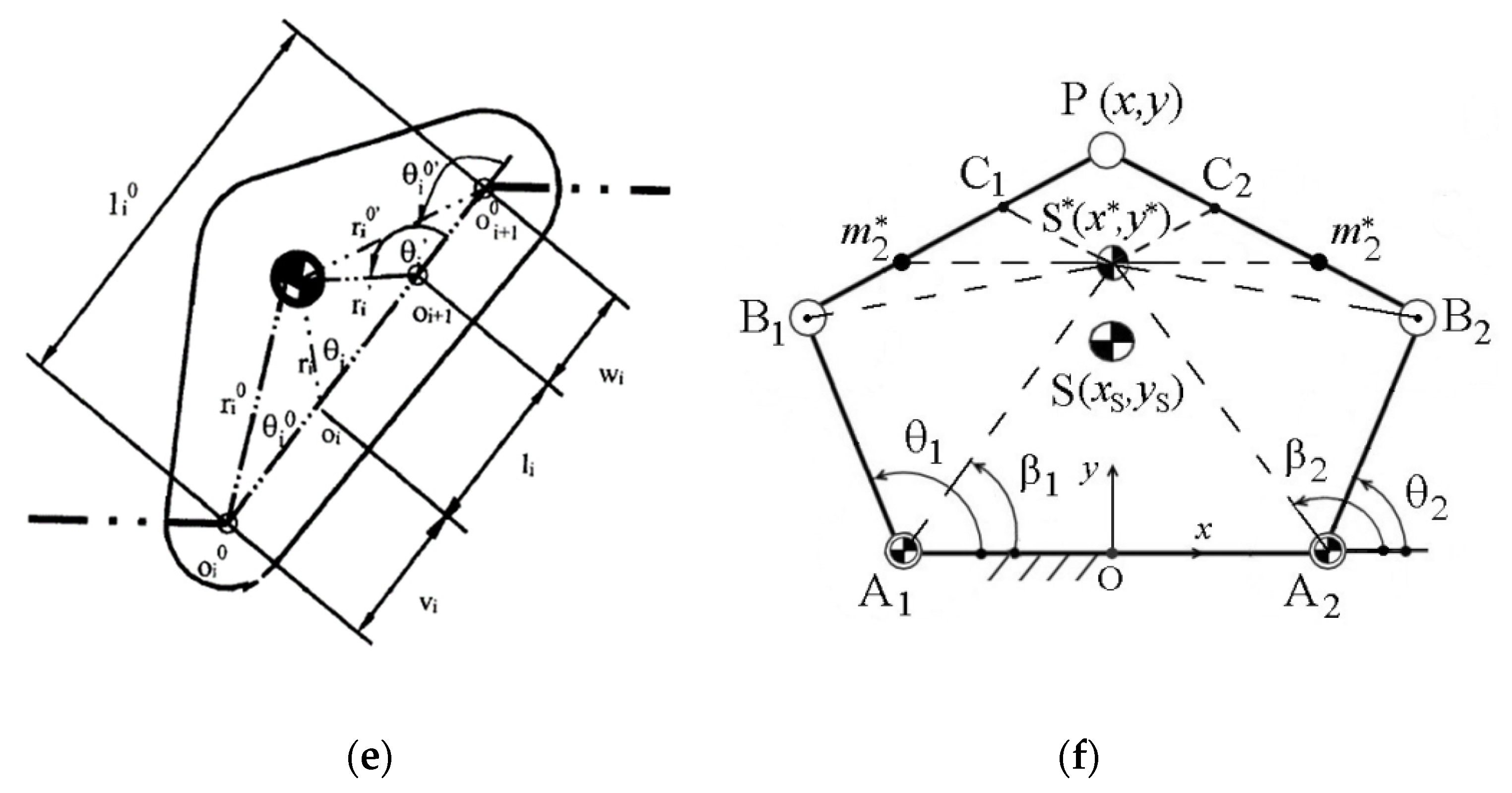
- Via center of mass acceleration control [11,12,13,14,15,16,17]. This approach is based on the optimal control of the acceleration of the manipulator center of masses. For this purpose, the “bang–bang” profile was used. The aim of the suggested method consists in the fact that the manipulator is controlled not by applying end-effector trajectories but by planning the displacements of the total mass center of moving links. Such a solution does not allow for complete balancing, but it leads to a significant decrease in shaking forces. In [17], a substituted point mass (Figure 1f) was found to replace the common center of mass of the 5R parallel manipulators as a virtual point. In this case, the motion planning of the substituted point mass can ensure a reduction of the shaking force.
This paper deals with the shaking force balancing problem of the Orthoglide [18,19] via the last-mentioned approach, taking into consideration the robot structure. The robot Orthoglide is a three-degrees-of-freedom parallel manipulator with a regular workspace and good compactness. Its three actuators are arranged according to the Cartesian coordinate space. The prototype and architecture of the robot are shown in Figure 2 and Figure 3.
Here we point out that this paper is an extended version of a work first published at the 29th International Conference on Robotics in Alpe-Adria-Danube Region (RAAD 2020) [20]. With regard to [20], additional simulation results are presented here, i.e., the balancing of shaking force, taking into account the varying payload and its sensitivity analysis. The rest of the paper is organized as follows: Section 2 describes the balancing approach based on optimal motion planning of the common center of mass; In Section 3, the numerical simulations in ADAMS software are conducted to validate the efficiency of the proposed balancing approach and the sensitivity to the design variables. In addition, the sensitivities of the shaking force and output position accuracy to the design variables of the Orthoglide are analyzed.
Now, let us consider the shaking force balancing of the Orthoglide.
2. Shaking Force Balancing of the Orthoglide
2.1. Problem Formulation
Let us first consider the kinematic architecture of the Orthoglide (Figure 3a). It consists of three identical kinematic chains that are formally described as , where , and denote the actuated prismatic, revolute, and parallelogram joints, respectively. The mechanism input is made up of three actuated orthogonal prismatic joints. The output body is connected to the prismatic joint through a set of three kinematic chains. Inside each chain, one parallelogram is used and oriented in a manner that the output body is restricted to translational movements only. The three parallelograms have the same lengths . The arrangement of the joints in the chains was defined to eliminate any constraint singularity in the Cartesian workspace. Each frame pointis fixed on the linear axis so that . The points and are located on the parallelogram, as is shown in Figure 1. The reference frame is located at the intersection of the prismatic joint axes and aligns the coordinate axis with them. The details of the design of the Orthoglide and its optimization can be found in [18,19].
For the Orthoglide geometrical model (see Figure 3b), the inverse kinematic equations [21] can be drives in a straightforward way as:
where , , are the configuration indices that are equal to ; The input vector of the three prismatic joints variables as and the output position vector of the tool center point as . Note that for the Orthoglide robot, a single inverse kinematic solution is reachable.
The shaking forces of mechanisms can be written in the form:
where is the total mass of the moving links of the manipulator, is the mass of the payload and is the acceleration of the total mass center. In the proceeding of 29th International Conference on Robotics in Alpe-Adria-Danube Region, the balancing problem of the Orthoglide was addressed without counting the varying payload . As mentioned above, see Section 1, the shaking force balancing via mass redistribution consists of adding counterweights in order to keep the total mass center of moving links stationary [22]. In this case, for any configuration of the manipulator and, as a result, the shaking force is canceled. It is obvious that the adding of supplementary masses as counterweights is not desirable because it leads to the increase of the total mass, of the overall size of the manipulator, the efforts in joints, the shaking moment and the input torques. Therefore, in the present study, it is proposed to minimize the shaking force via reduction of the total mass center acceleration:
i.e., to apply an optimal control of the total mass center of moving links that allows one to reduce the maximal value of its acceleration.
For this purpose, let us consider the control of the spatial parallel manipulator Orthoglide through the motion planning of its center of mass. To ensure it, let us assume that the center of mass moves along a straight line between its initial and final positions. Thus, the motion profile used on this path will define the values of shaking forces. For the same displacement of the total center of mass and the displacement time , the maximal value of the acceleration changes following the motion profile [23]: For quantic polynomial profile, the ; For the “bang–bang” profile, . It means the application of the “bang–bang” law theoretically brings about a reduction of 30.7% of the maximal value of the acceleration. Hence, to minimize the maximum value of the acceleration of the total mass center and, as a result, shaking forces, the “bang–bang” profile should be used. Thus, by reducing the acceleration of the center of mass of the Orthoglide, a decrease in its shaking forces is achieved. Therefore, to achieve the shaking force balancing through the approach described above, it is necessary to consider the relationship between the input parameters and the center of mass positions of the Orthoglide.
2.2. The Relationship between the Total Center of Mass and the Input Parameters of the Robot
In order to control the manipulator according to the method described above, it is necessary to establish the relationship between the displacement of the total center of mass and the input parameters , i.e., for the given position and the law of motion of the common center of mass (CoM) of the manipulator determine its input displacements. Then, by means of the obtained input parameters via forward kinematics, determine the position of the output axis . For this purpose, it is necessary to establish the relationship between the common center of mass of the manipulator and its input parameters.
Let us start this issue with the initial and final positions of the platform and . So, by inverse kinematics [21], the input angles corresponding to these positions will be determined: and . The corresponding values of the common CoM of the manipulator can also be found: and . The displacement of the total center of mass is . Subsequently, a straight line connecting the initial and final positions of the comment center mass of the manipulator can be established, and its motion planning by “bang–bang” profile with the time interval can be ensured: , i.e.,
Let us now consider the relationship between and the input displacement .
The common CoM of the manipulator can be expressed as:
where is the number of the moving link , is the coordinate vector of the total mass center of the manipulator, is the coordinate vector of the linkage , is the mass of the linkage ; is the coordinate vector of the payload, is the mass of the payload; is the total mass of the Orthoglide including the payload.
In the developed prototype, the slider of the prismatic joint is designed as the body , where is not on the three axes but has an offset named . At the same time, . Thus, the coordinates of the joints along the X, Y and Z axes are the followings:
X-axis: ; ; .
Y-axis: ; ; .
Z-axis: ; ; .
The mass centers of the parallelograms can be written as: , and their masses are . The masses center of the three actuated links is: , the masses of input links are denoted as . The coordinates of the mass center of the joint of the end-effector are , and its mass is .
With the masses of the corresponding links, the expressions of the total center of mass of the moving links of the Orthoglide can be expressed as:
where is the total mass of the moving components; is the length of the longer side of the three parallelograms; represents the distance between the joint and the mass center of parallelograms.
According to the proposed method, the displacement of the total center of mass should follow “bang–bang” motion profile , i.e.,
Note that the output parameters of the manipulator Orthoglide can be expressed with the functions, including the input parameters via direct kinematics [21]. Thus, Equation (6) becomes a group of three equations expressed with three unknowns , and it has a unique solution. Finally, the time-varying input displacements of the actuated prismatic joints can be obtained in order to ensure the displacement of the CoM.
3. Illustrative Example via CAD Model
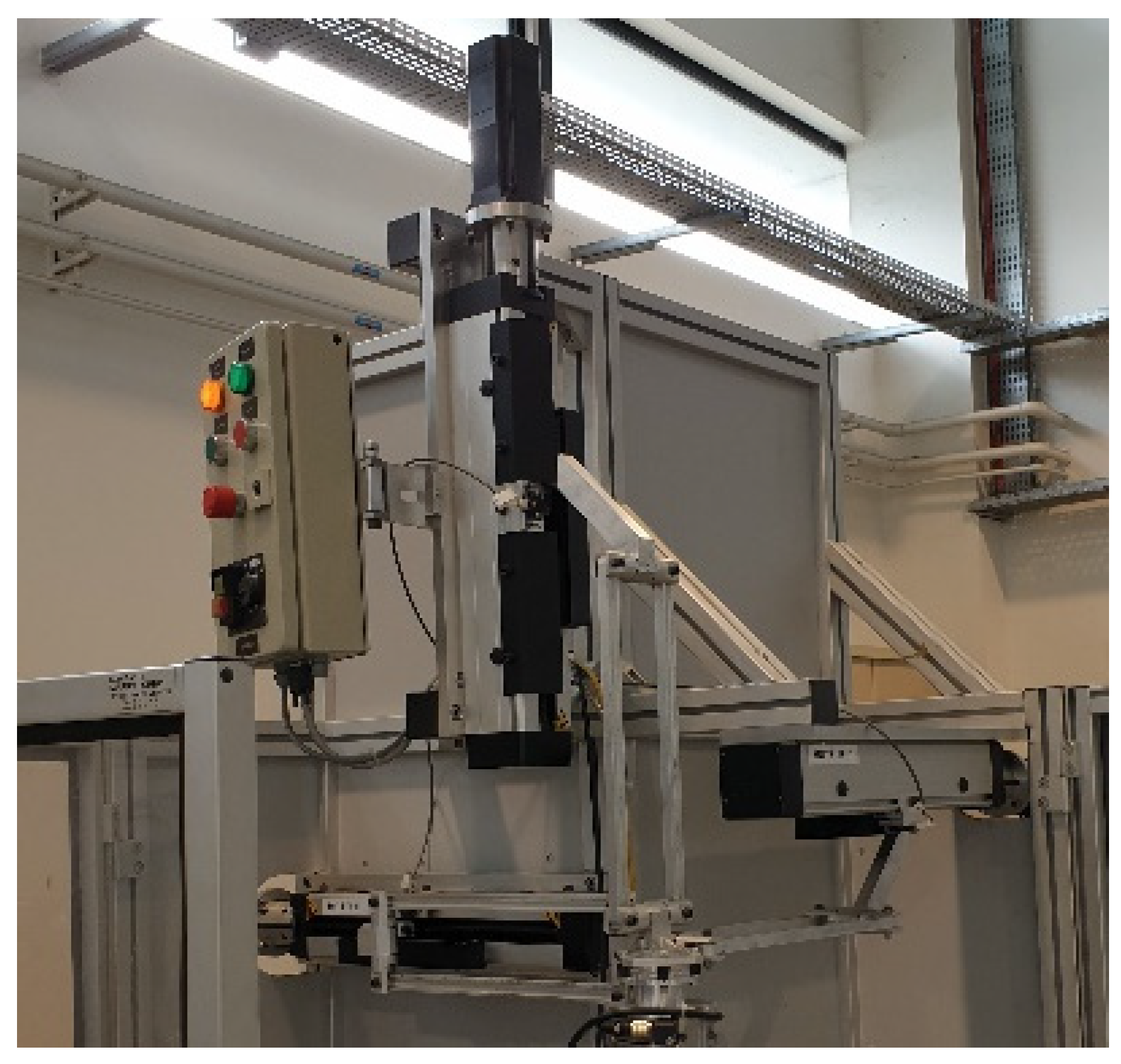
To validate the proposed method, numerical simulations are conducted in ADAMS software. We created a CAD model and carried out the simulations by applying the following parameters of the Orthoglide [24], which correspond to the geometrical parameters of the prototype developed in LS2N (Figure 2). The detailed geometric parameters follow. The lengths of the longer side of the three parallelograms are , the distances between the joint and the mass center of the parallelograms are , the configuration indices of the current mechanism are . The masses of sliders are , the masses of the parallelograms are , and the mass of the revolute joint is . The trajectory of the output axis P of the platform is given by its initial position with the coordinates: , , and the final position with the coordinates: , , . The corresponding input displacements are determined via inverse kinematics:, , , , . The coordinates of the common CoM of the manipulator for two positions were found: , , , , , . The traveling time of this trajectory is , the designed acceleration of the center of mass is .
3.1. Balancing of the Orthoglide without Taking into Account the Payload
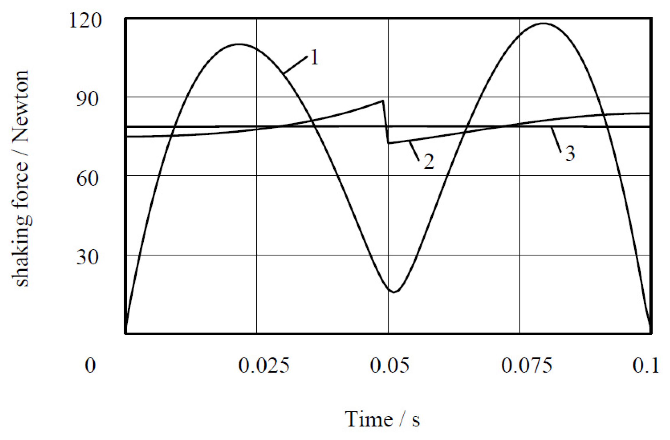
The traditional control strategy is based on the trajectory and motion planning of the end-effector. In the application of the pick-and-place robot, the displacement of the end-effector is defined as a straight line and parameterized with a motion profile such as a quantic polynomial profile. With the proposed approach in this paper, the trajectory of the end-effector is not defined, but the trajectory of the CoM. Then, the “bang–bang” motion profile is applied to the trajectory of the CoM. Thus, in this section, three studied cases are designed in order to see the efficiency of the proposed method:
- Case 1: defining the displacement of the end-effector of the unbalanced manipulator as a straight line and parameterized with “fifth-order polynomial” profile;
- Case 2: defining the displacement of the end-effector of the unbalanced manipulator as a straight line and parameterized with “bang–bang” profile;
- Case 3: the generation of the displacement of the manipulator center of mass as a straight line and parameterized with the “bang–bang” profile.
By comparing cases 1 and 2, we can see the necessity of using “bang–bang” law; by comparing cases 2 and 3, the advantage of CoM motion planning become obvious; in comparison of cases 1 and 3, the difference between the traditional control method and proposed one becomes evident.
The simulation results (Figure 4) show that, compared to the traditional control technique (case 1), the shaking force was reduced up to 33.2% by applying the “bang–bang” law to the CoM (case 3) without carrying a payload. Employing the “bang–bang” motion on the end-effector (case 2) reduces the shaking force by 24.9%.
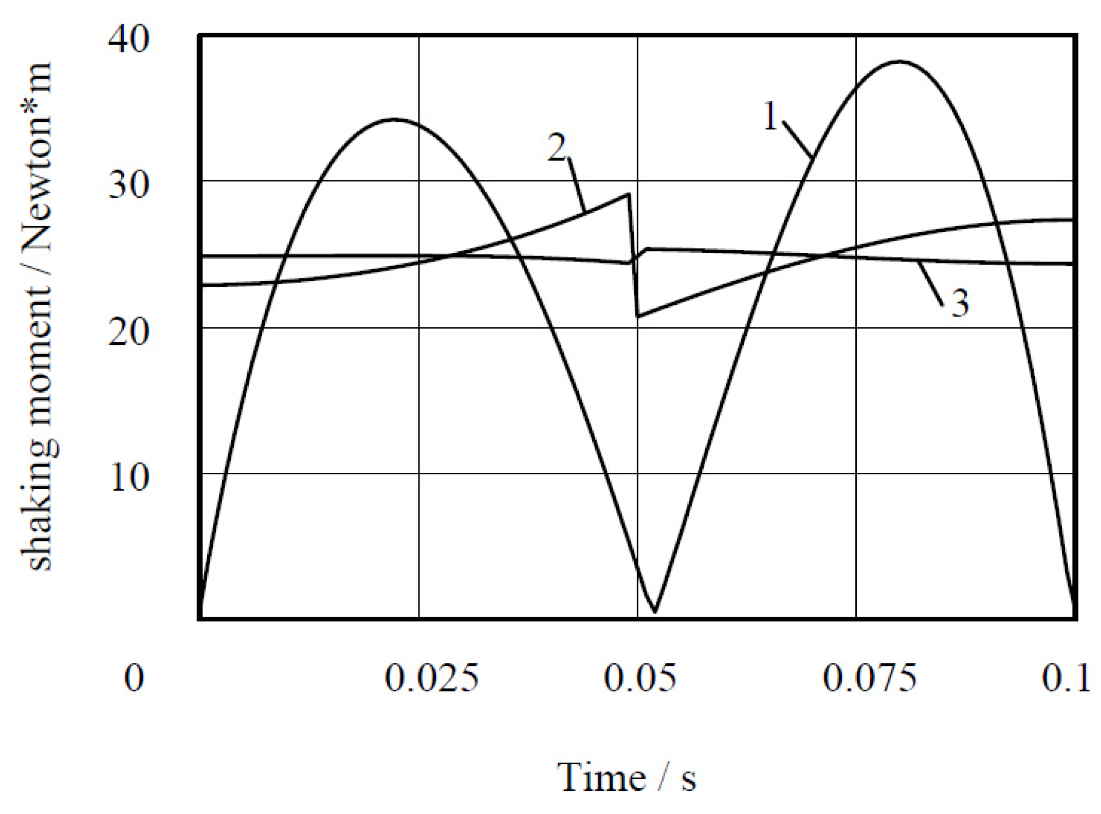
Compared to the increase of the shaking moment of the balancing method based on adding counterweights, the shaking moment (see in Figure 5) has a reduction of 33.6% with the approach based on the motion planning of the CoM (case 3). The method that defines the motion of the end-effector with “bang–bang” (case 2) motion profile reduces the shaking moment by 23.8%.
The curves of case 3 are nearly straight lines and have largely reduced the maximal value of the shaking force and shaking moment, which is benefiting from the proposed balancing technique. Obviously, the motion control of the CoM of the Orthoglide is more efficient.
Another advantage of this method is its simplicity and versatility. In the case of changing trajectory, it is just necessary to provide the initial and final coordinates of the end-effector, calculate the input parameters according to the proposed method and implemented them in the manipulator control system.
3.2. Balancing of the Orthoglide While Taking into Account the Payload
With the balancing method by adding counterweights, once the payload is changed, the mass redistribution needs to be redone, which brings about the complexity of the balancing process.
However, the proposed approach by optimal motion planning of the CoM is still efficient, taking into account the varying payload because the motion planning can be conducted without modifying the robot components and configuration. In view of the payload capacity of the Orthoglide (5 kg), Table 1 and Table 2 demonstrate the shaking force and shaking moment for three cases when the Orthoglide is carrying a payload. The variations and reduction ratio of the shaking force and the shaking moment taking into account the payloads are, respectively, presented in Table 1 and Table 2.
As is shown in Table 1, the shaking force of the Orthoglide was reduced up to 33.2%. Following the increase of the payload, the reduction ratio is approaching the theoretical value of 30.7%. Thus, we have the conclusion that, with the proposed balancing approach, a minimum reduction (30.7%) of the shaking force can be achieved. Compared to case 3, case 2 has a minimum reduction of the shaking force of 24.9%.
It should be noted that the purpose of these simulations was not an illustration of the decrease in the shaking moment. However, it was considered useful to give the simulation results, which show that a decrease in shaking force is accompanied by a decrease in shaking moment. It can be considered a further advantage of the suggested balancing solution.
3.3. Sensitivity Analysis of the Shaking Force and Shaking Moment
In the current industry, manufacturing errors are unavoidable and should be considered during the design process in order to ensure high accuracy of achieved results. With the proposed balancing strategy, the mass of the payload is one of the design variables, which can largely influence the final values of shaking forces and shaking moments acting on the frame. During the balancing process, if a mass error exists, the balancing condition can be different.
The shaking force of the Orthoglide shown in Equation (2) can also be written as the sum of the inertial forces of all the moving components:
Thus, the substituted mass center of the Orthoglide can be expressed as:
where the accelerations of the links are:
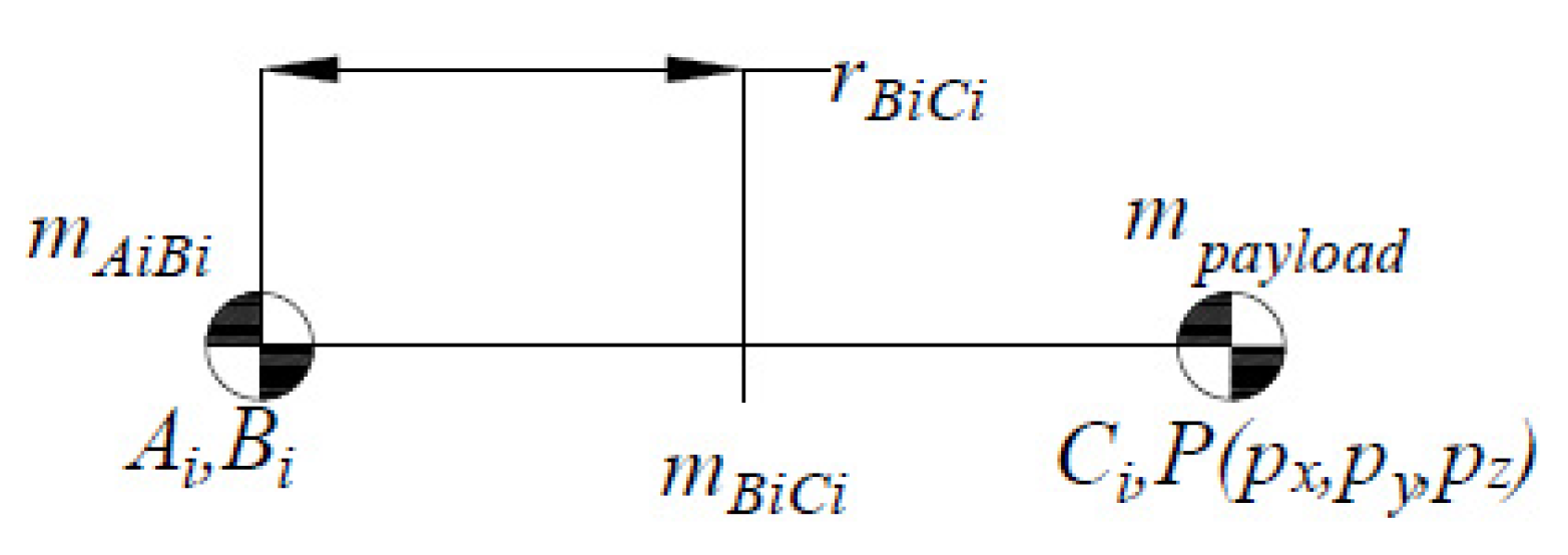
the replaced point mass on is:
where is the distance between joints and the mass center of the link . (See in Figure 6).
Thus, the sensitivities of the shaking force to the design variables (The mass and length parameters of the links) of the Orthoglide can be obtained as follows:
From the equations presented above (12–16), it is obvious that the sensitivities of the shaking force to the design variables depend on the acceleration of the end-effector and input sliders , which are nonlinear and time-varying, and the values of the variables themselves.
To illustrate the sensitivities of the shaking force balancing approach proposed in this article, an error of 10% of the design variables’ value is applied during the balancing process. Then a series of simulations are conducted in ADAMS software. It should be noted that each simulation includes only one variable with an error, in order to identify the input parameters which make the largest contribution to the shaking force errors. Here, the payload is 1 kg. The trajectory of the output axis P of the platform is given by its initial position with the coordinates: , , and the final position with the coordinates: , , . The traveling time of this trajectory is , the designed acceleration of the center of mass is . In addition, taking into account that the Orthoglide has three identical kinematic chains, only one arm’s design variables one observed. We declare that the error of the mass of link AB is denoted as , the mass error of the payload carried by the end-effector is denoted as , the length error of link AB is denoted as and the position error of the mass center of link AB is denoted as .
As we can see from Table 3, not only the error of shaking force is presented while the length error exists, but also the output coordinates errors of the end-effector. The latter is very important because it decides the output accuracy and reliability of the mechanism. Thus, the manufacturing accuracy, design tolerances and clearances, etc., should be proper in order to ensure output accuracy.
The simulation results in Table 4 and Table 5 show the sensitivities of shaking force and output position. Table 4 shows that the quality of the proposed shaking force balancing approach is relatively sensitive to the mass of the prismatic slider . However, the mass of the slider does not influence the accuracy of the output positions. As we can see from Table 4 and Table 5, both shaking force and positions of the end-effector are not very sensitive to the design variables , which means the proposed balancing solution has good stability under manufacturing errors (10%).
4. Conclusions
It is known that the shaking force balancing by counterweights mounted on the moving links is more appropriate for serial and planar parallel manipulators. It is much more difficult for parallel spatial manipulators. Therefore, in this paper, an alternative method based on optimal acceleration control of the common CoM is applied for shaking forces minimization of the Orthoglide robot. The suggested balancing technique consists in the fact that the Orthoglide is controlled not by applying platform trajectories but by motion planning of the total mass center of moving links. The trajectories of the total mass center of the manipulator are defined as straight lines and are parameterized with a “bang–bang” profile. Such a control approach allows the reduction of the maximum value of the center of mass and consequently the shaking force. The numerical simulations show the efficiency of the proposed solution.
Then, the sensitivities of the shaking force while applying the proposed balancing strategy to the design variables of the Orthoglide were analyzed. It is shown that the errors of the shaking force are acceptable.
Now, future works concern the experimental validation of the suggested balancing technique via tests that will be carried out on the prototype of the Orthoglide developed in LS2N (Figure 2).
Author Contributions
Conceptualization, methodology and investigation, software, validation, data curation, writing—original draft preparation, writing—review and editing, J.G., V.A., D.C. and P.L. All authors have read and agreed to the published version of the manuscript.
Funding
This research was supported by a scholarship funded by the China Scholarship Council.
Institutional Review Board Statement
Not applicable.
Informed Consent Statement
Not applicable.
Data Availability Statement
Not applicable.
Conflicts of Interest
The authors declare no conflict of interest.
References
- Filaretov, V.F.; Vukobratovic, M.K. Static balancing and dynamic decoupling of the motion of manipulation robots. Mechatronics 1993, 3, 767–783. [Google Scholar] [CrossRef]
- Bayer, A.; Merk, G. Industrial Robot with a Weight Balancing System. Patent EP 2011, 301, 727. [Google Scholar]
- Gosselin, C.M. Gravity compensation, static balancing and dynamic balancing of parallel mechanisms. In Smart Devices and Machines for Advanced Manufacturing; Springer: London, UK, 2008; pp. 27–48. [Google Scholar]
- Agrawal, S.K.; Fattah, A. Reactionless space and ground robots: Novel design and concept studies. Mech. Mach. Theory 2004, 39, 25–40. [Google Scholar] [CrossRef]
- Fattah, A.; Agrawal, S.K. Design and modeling of classes of spatial reactionless manipulators. In Proceedings of the 2003 IEEE International Conference on Robotics and Automation (ICRA), Taipei, Taiwan, 14–19 September 2003; pp. 3225–3230. [Google Scholar]
- Fattah, A.; Agrawal, S.K. Design arm simulation of a class of spatial reactionless manipulators. Robotica 2005, 23, 75–81. [Google Scholar] [CrossRef]
- Wijk, V.; van der Herder, J.L. Dynamic Balancing of Clavel’s Delta Robot. In Computational Kinematics; Kecskeméthy, A., Müller, A., Eds.; Springer: Berlin/Heidelberg, Germany, 2009; pp. 315–322. [Google Scholar]
- Alici, G.; Shirinzadeh, B. Optimum force balancing with mass distribution and a single elastic element for a five-bar parallel manipulator. In Proceedings of the 2003 IEEE International Conference on Robotics and Automation (ICRA), Taipei, Taiwan, 14–19 September 2003; pp. 3666–3671. [Google Scholar]
- Alici, G.; Shirinzadeh, B. Optimum force balancing of a planar parallel manipulator. Proc. Inst. Mech. Eng. Part C J. Mech. Eng. Sci. 2003, 217, 515–524. [Google Scholar] [CrossRef]
- Ouyang, P.R.; Zhang, W.J. A Novel Force Balancing Method for Real-Time Controllable Mechanisms. In Proceedings of the ASME 2002 International Design Engineering Technical Conferences and Computers and Information in Engineering Conference, Montreal, QC, Canada, 29 September–2 October 2002; pp. 183–190. [Google Scholar]
- Briot, S.; Arakelian, V.; Le Baron, J.-P. Shaking Force Minimization of High-Speed Robots via Center of Mass Acceleration Control. Mech. Mach. Theory 2012, 57, 1–12. [Google Scholar] [CrossRef] [Green Version]
- Briot, S.; Arakelian, V.; Sauvestre, N.; Baron, J.-P.L. Shaking Forces Minimization of High-Speed Robots via an Optimal Motion Planning. In ROMANSY 18 Robot Design, Dynamics and Control; Springer: Vienna, Austria, 2010; pp. 307–314. [Google Scholar]
- Arakelian, V. Design of Partially Balanced 5R Planar Manipulators with Reduced Center of Mass Acceleration (RCMA). In ROMANSY 21—Robot Design, Dynamics and Control; Parenti-Castelli, V., Schiehlen, W., Eds.; Springer: Udine, Italy, 2016; Volume 569, pp. 113–122. [Google Scholar]
- Arakelian, V.; Geng, J.; Fomin, A.S. Minimization of Shaking Loads in Planar Parallel Structure Manipulators by Means of Optimal Control. J. Mach. Manuf. Reliab. 2018, 47, 303–309. [Google Scholar] [CrossRef]
- Geng, J.; Arakelian, V. Design of Partially Balanced Planar 5R Symmetrical Parallel Manipulators via an Optimal Motion Planning. In Advances in Mechanism and Machine Science. IFToMM 2019; Uhl, T., Ed.; Springer: Krakow, Poland, 2019; Volume 73, pp. 2211–2220. [Google Scholar]
- Geng, J.; Arakelian, V. Partial Shaking Force Balancing of 3-RRR Parallel Manipulators by Optimal Acceleration Control of the Total Center of Mass. In Multibody Dynamics 2019, ECCOMAS 2019, Computational Methods in Applied Sciences; Kecskeméthy, A., Flores, F.G., Eds.; Springer: Cham, Germany, 2019; Volume 53, pp. 375–382. [Google Scholar]
- Geng, J.; Arakelian, V. Balancing of Planar 5R Symmetrical Parallel Manipulators Taking into Account the Varying Payload. In ROMANSY 23—Robot Design, Dynamics and Control, ROMANSY 2020, CISM International Center for Mechanical Sciences (Courses and Lectures); Venture, G., Solis, J., Takeda, Y., Konno, A., Eds.; Springer: Cham, Germany, 2020; Volume 601, pp. 372–379. [Google Scholar]
- Wenger, P.; Chablat, D. Kinematic Analysis of a New Parallel Machine Tool: The Orthoglide. In Advances in Robot Kinematics; Lenarčič, J., Stanišić, M.M., Eds.; Springer: Dordrecht, The Netherlands, 2000; pp. 305–314. [Google Scholar]
- Chablat, D.; Wenger, P. Architecture Optimization of a 3-DOF Translational Parallel Mechanism for Machining Applications, the Orthoglide. IEEE Trans. Robot. Autom. 2003, 19, 403–410. [Google Scholar] [CrossRef]
- Geng, J.; Arakelian, V.; Chablat, D.; Lemoine, P. Shaking Force Balancing of the Orthoglide. In Advances in Service and Industrial Robotics. RAAD 2020. Mechanisms and Machine Science; Zeghloul, S., Laribi, M., Arevalo, J.S., Eds.; Springer: Cham, Germany, 2020; Volume 84, pp. 227–234. [Google Scholar]
- Pashkevich, A.; Chablat, D.; Wenger, P. Kinematics and Workspace Analysis of a Three-Axis Parallel Manipulator: The Orthoglide. Robotica 2006, 24, 39–49. [Google Scholar] [CrossRef] [Green Version]
- Arakelian, V.; Briot, S. Balancing of Linkages and Robot Manipulators: Advanced Methods with Illustrative Examples; Springer: Cham, Switzerland, 2015. [Google Scholar]
- Khalil, W.; Dombre, E. Modeling, Identification and Control of Robots; Butterworth-Heinemann: Oxford, UK, 2003. [Google Scholar]
- Guegan, S.; Khalil, W.; Lemoine, P. Identification of the dynamic parameters of the Orthoglide. In Proceedings of the 2003 IEEE International Conference on Robotics and Automation(ICRA), Taipei, Taiwan, 14–19 September 2003; pp. 3666–3671. [Google Scholar]
Figure 1.
(a) Motors used as counterweights [2]; (b) parallel spatial manipulator balanced by adding counterweights [3]; (c) shaking force balancing by adding a pantograph in oder to keep the center of mass (CoM) stationary [7]; (d) a combination of a proper distribution of link masses and two springs [9]; (e) two-step kinematic parameter adjustment in the adjusting kinematic parameters method [10]; (f) the optimal acceleration control of the substituted center of mass of a 5R parallel manipulator [17].


Figure 2.
The prototype of the Orthoglide (LS2N).

Figure 3.
(a) The structure of the Orthoglide; (b) the geometrical model of the Orthoglide.

Figure 4.
Variations of shaking forces for three studied cases.

Figure 5.
Variations of shaking moments for three studied cases.

Figure 6.
The center mass of the parallelogram.


Table 1.
The shaking force and its reduction of the Orthoglide while carrying a payload.
| Mass of Payload/kg | Shaking Force 1/Newton · m | Reduction 2/% | |||
|---|---|---|---|---|---|
| Case 1 | Case 2 | Case 3 | Case 2 | Case 3 | |
| 0 | 117.99 | 88.56 | 78.86 | 24.9 | 33.2 |
| 1 | 212.08 | 152.82 | 144.57 | 27.9 | 31.8 |
| 2 | 306.73 | 218.08 | 210.55 | 28.9 | 31.3 |
| 3 | 401.55 | 283.65 | 276.31 | 29.3 | 31.2 |
| 4 | 496.43 | 349.36 | 342.22 | 29.6 | 31.1 |
| 5 | 591.35 | 415.14 | 408.14 | 29.8 | 30.9 |
1 the maximum value of the shaking force during the movement. 2 the reduction ratio of shaking force is calculated by .
Table 2.
The shaking moment and its reduction of the Orthoglide while carrying a payload.
| Mass of Payload/kg | Shaking Moment 1/Newton · m | Reduction 2/% | |||
|---|---|---|---|---|---|
| Case 1 | Case 2 | Case 3 | Case 2 | Case 3 | |
| 0 | 38.19 | 29.11 | 25.35 | 23.8 | 33.6 |
| 1 | 64.11 | 47.18 | 43.66 | 26.4 | 31.9 |
| 2 | 90.08 | 65.25 | 61.82 | 27.6 | 31.4 |
| 3 | 116.06 | 83.33 | 79.93 | 28.2 | 31.1 |
| 4 | 142.03 | 101.40 | 98.02 | 28.6 | 31.0 |
| 5 | 168.01 | 119.47 | 116.09 | 28.9 | 30.9 |
1 the maximum value of the shaking moment during the movement. 2 the reduction ratio of shaking moment is calculated by .
Table 3.
The errors of shaking force and end-effector position taking into account the errors.
| Input Errors | Output Errors | |||||||
|---|---|---|---|---|---|---|---|---|
| 0.04 | 0 | 0 | 0 | 0 | 0.077 | 0 | 0 | 0 |
| 0 | 0.1 | 0 | 0 | 0 | 0.187 | 0 | 0 | 0 |
| 0 | 0 | 31 | 0 | 0 | 2.887 | 37.296 | 6.048 | 11.824 |
| 0 | 0 | 0 | 16 | 0 | 0.025 | 0 | 0 | 0 |
| 0 | 0 | 0 | 0 | 0.02 | 0.202 | 0 | 0 | 0 |
is the difference of the shaking force. are the output coordinates errors of the end-effector .
Table 4.
The sensitivities of the shaking force to the design variables.
| 10.105 | 1.930 | 1.874 | 1.581 |
Table 5.
The sensitivities of the shaking force and output position to the design variables.
| 0.093 | 1.203 | 0.195 | 0.381 |
Publisher’s Note: MDPI stays neutral with regard to jurisdictional claims in published maps and institutional affiliations. |
© 2021 by the authors. Licensee MDPI, Basel, Switzerland. This article is an open access article distributed under the terms and conditions of the Creative Commons Attribution (CC BY) license (http://creativecommons.org/licenses/by/4.0/).
Share and Cite
MDPI and ACS Style
Geng, J.; Arakelian, V.; Chablat, D.; Lemoine, P. Balancing of the Orthoglide Taking into Account Its Varying Payload . Robotics 2021, 10, 30. https://0-doi-org.brum.beds.ac.uk/10.3390/robotics10010030
AMA Style
Geng J, Arakelian V, Chablat D, Lemoine P. Balancing of the Orthoglide Taking into Account Its Varying Payload . Robotics. 2021; 10(1):30. https://0-doi-org.brum.beds.ac.uk/10.3390/robotics10010030
Chicago/Turabian StyleGeng, Jing, Vigen Arakelian, Damien Chablat, and Philippe Lemoine. 2021. "Balancing of the Orthoglide Taking into Account Its Varying Payload " Robotics 10, no. 1: 30. https://0-doi-org.brum.beds.ac.uk/10.3390/robotics10010030
Note that from the first issue of 2016, this journal uses article numbers instead of page numbers. See further details here.