Model-Based Flow Rate Control with Online Model Parameters Identification in Automatic Pouring Machine


1
Course of Mechanical Engineering, Integrated Graduate School of Medicine, Engineering, and Agricultural Sciences, University of Yamanashi, 4-3-11, Takeda, Kofu 400-8511, Japan
2
Department of Mechanical Engineering, Graduate Faculty of Interdisciplinary Research, University of Yamanashi, 4-3-11, Takeda, Kofu 400-8511, Japan
*
Author to whom correspondence should be addressed.
Robotics 2021, 10(1), 39; https://0-doi-org.brum.beds.ac.uk/10.3390/robotics10010039
Submission received: 31 January 2021
/
Revised: 20 February 2021
/
Accepted: 24 February 2021
/
Published: 2 March 2021
(This article belongs to the Section Industrial Robots and Automation)
Abstract
:In this study, we proposed an advanced control system for tilting-ladle-type automatic pouring machines in the casting industry. Automatic pouring machines have been introduced recently to improve the working environment of the pouring process. In the conventional study on pouring control, it has been confirmed that the pouring flow rate control contributes to improving the accuracy of the entire automatic pouring machine, such as the outflow liquid’s falling position from the ladle, the liquid’s weight filled in the mold, and the sprue cup’s liquid level. However, the conventional control system has problems: it is not easy to precisely pour the liquid in the ladle with a large tilting angle, and it takes time to adjust the control parameters. Therefore, we proposed the feedforward pouring flow rate control system, constructed by the pouring process’ inverse model with the online model parameters identification. In this approach, we derived the pouring process’ mathematical model, representing precisely the pouring process with the ladle’s large tilting angle. The model parameters in the pouring process’ inverse model in the controller are updated online via the model parameters identification. To verify the proposed pouring control system’s efficacy, we experimented using the tilting-ladle-type automatic pouring machine. In the experimental results, the mean absolute error between the outflow liquid’s weight and the reference weight was improved from 0.1346 at the first pouring to 0.0498 at the fifth pouring. Moreover, the model parameters were identified within 4 s. Therefore, it enables updating the controller’s parameters within each pouring motion interval by the proposed approach.
1. Introduction
Casting products are widely used in automobile parts, machine tools, daily necessities, and other fields. Various casting types include continuous casting, die casting, and sand molded casting. Continuous casting is a manufacturing method in which the material is melted, continuously poured into a mold, and rapidly cooled in the mold to take out the product, making it highly productive and suitable for mass production. Control systems for the tundish’s liquid level have been proposed to improve the products’ quality [1,2,3]. In die casting, the molten metal is injected into a metal mold and cooled to form a shape. It has high-dimensional accuracy and is suitable for mass production than the other methods [4]. On the basis of the Taguchi method [5], the method has been proposed in which CAE analysis is applied and the defective rate is reduced by adjusting the injection parameters [6,7].
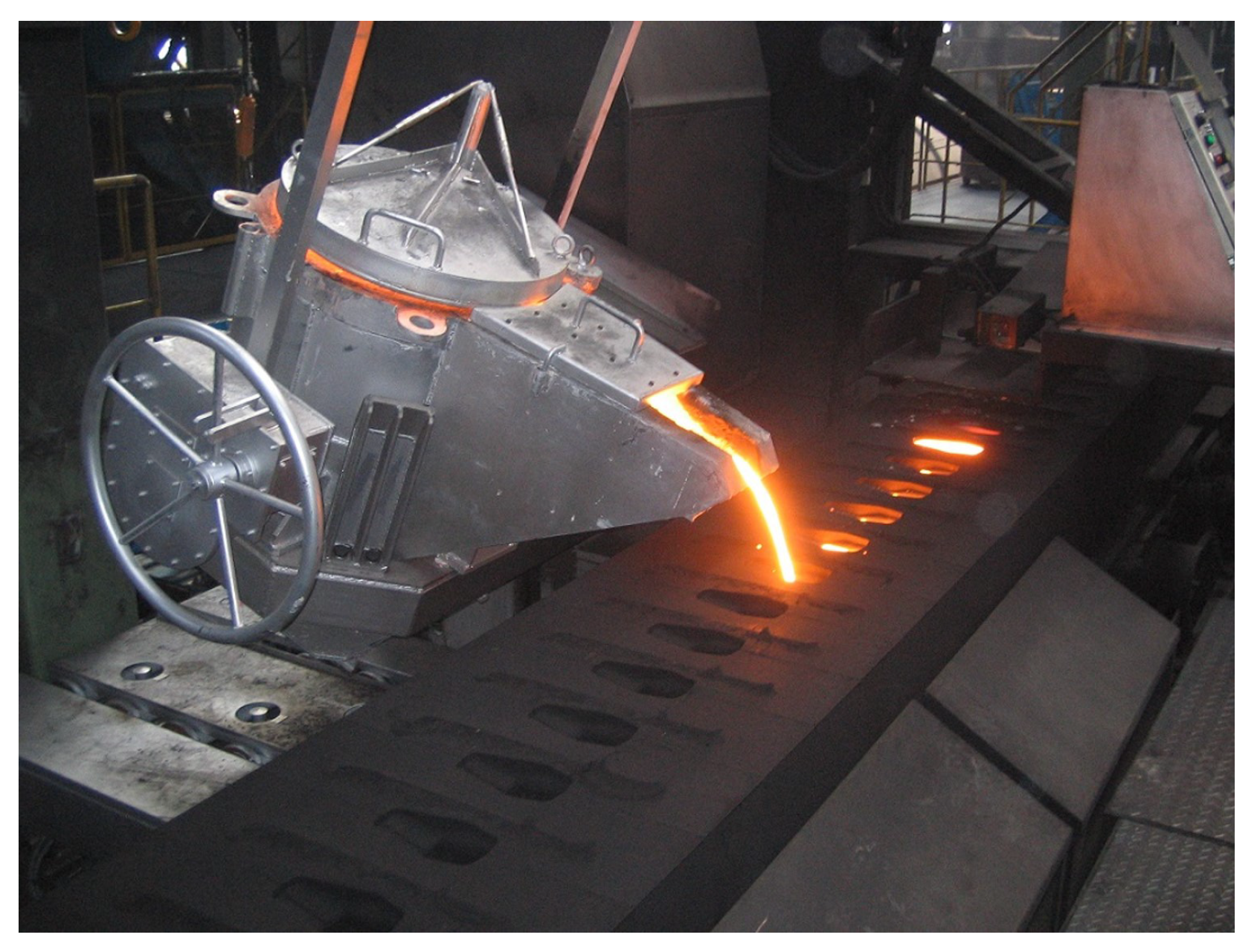
Sand molded casting is a traditional casting method used for high-mix, low-volume production [8]. A high-dissolution temperature is essential for iron and copper castings. Sand molded casting can mold casting products with a complicated shape. However, the pouring process in which the ladle’s molten metal is poured into the mold is a harsh environment with a high temperature and dust for workers. The casting products’ quality also varies because of the different worker’s skills. Automatic pouring machines [9,10,11] have been developed to solve these problems, such as include a tilting-ladle-type [12], stopper-nozzle-type [13], and pressurizing-type machines [14]. The tilting-ladle-type automatic pouring machine (Figure 1) can be installed easily into the casting production line because the machine’s motion is similar to a traditional pouring operation with the worker.
Previous studies proposed the sloshing suppression controls [15,16] and the supervisory controls [17] for the tilting-ladle-type automatic pouring machines. In previous studies of the pouring control, the linear time invariant model [18] and the linear parameters varying model [17,19] were applied as the model of pouring process with tilting ladle. The physics model with nonlinearity of the pouring process based on the liquid’s volume balance in the ladle and Bernoulli’s theorem has been derived in [12,20]. The pouring flow rate model based on the ladle’s liquid volume reduction by tilting ladle has also been proposed in [21]. Model-based pouring flow rate control [12,20] realizes high-precision pouring in an ideal environment without disturbance, contributing to higher accuracy of the automatic pouring system. In the automatic pouring machines that can directly manipulate the pouring flow rate [22], the extended Kalman filter was applied to estimate the pouring flow rate and to realize the user’s desired pouring pattern. The flow rate feedback control system has been designed using the flatness-based control approach [23]. On the basis of the pouring flow rate control approach, the control system of the liquid level in the sprue cup has been developed [24].
However, the model parameters in conventional model-based pouring control systems have been identified in the preliminary experiments using a trial-and-error process. Suppose the liquid flow conditions are changed from the preliminary experiments. In that case, the pouring control system’s accuracy can be degraded. The method for automatically identifying each pouring model parameters has been proposed to solve these problem [25]. However, calculating the model parameters identification is time-consuming because the downhill simplex method [26,27] has been used as the numerical search of the model parameters.
On the basis of the pouring model, we proposed the feedforward-type pouring flow rate control with the online identification of the model parameters, such as the ladle’s tilting angle at the start of the outflow liquid from the ladle, the liquid density, and the flow rate coefficient in a short time. As it is required to construct simply the real-time motion control in the industrial controller with little processing power, we applied the feedforward-type pouring flow rate control as the motion control of the automatic pouring machine. Moreover, we constructed additionally the online model parameters identification to the pouring flow rate control. To identify the model parameters, we used the golden section method [28,29] and Gauss–Newton method [30,31]. We also used the look-up table to transform the model parameters for calculation time shortening. Moreover, we proposed the mathematical model, representing precisely the pouring process even with the ladle’s large tilting angle.
We verified the efficacy of the proposed pouring flow rate control system through experiments with the tilting-ladle-type automatic pouring machine in our laboratory.
2. Automatic Pouring Machine
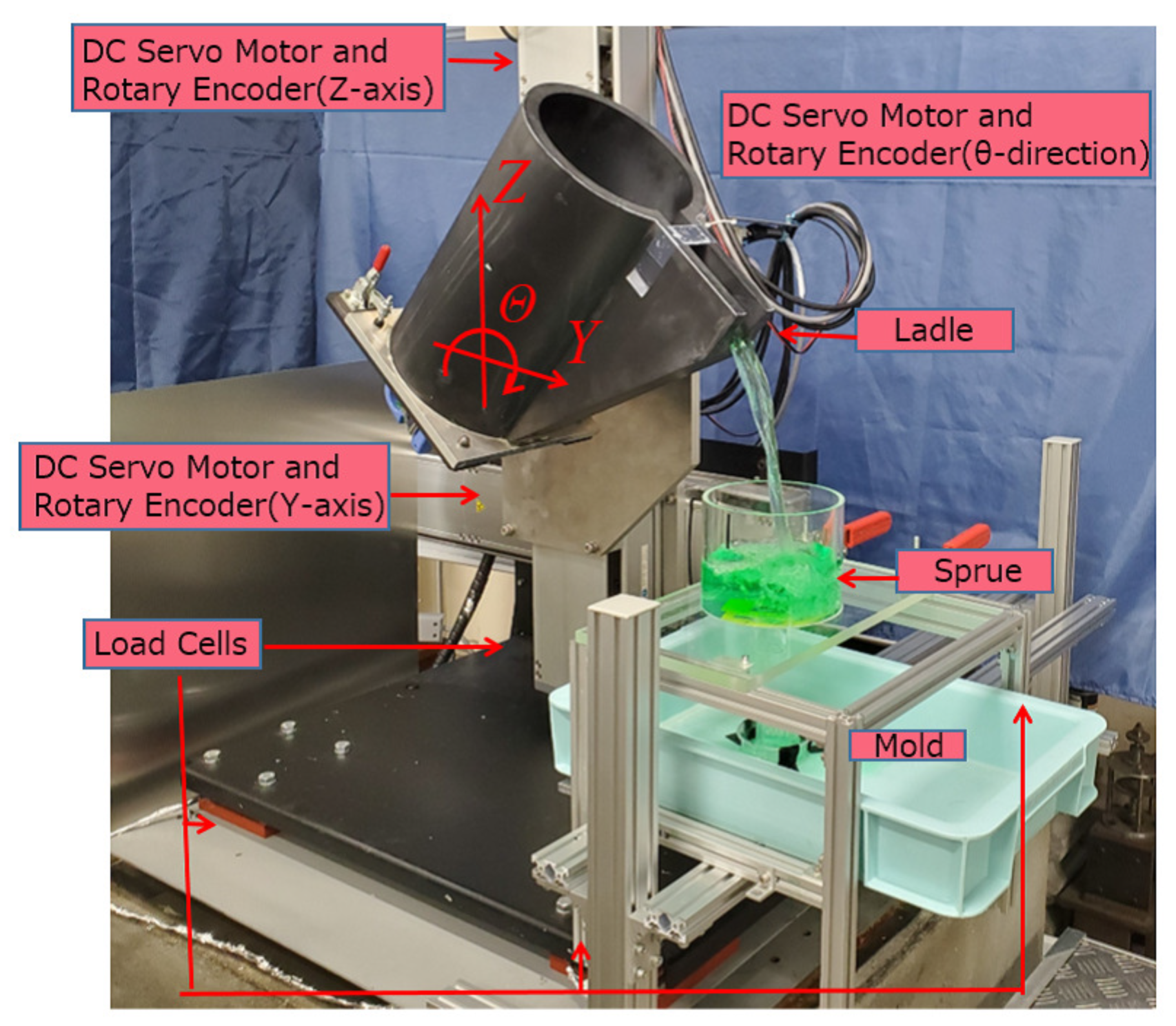
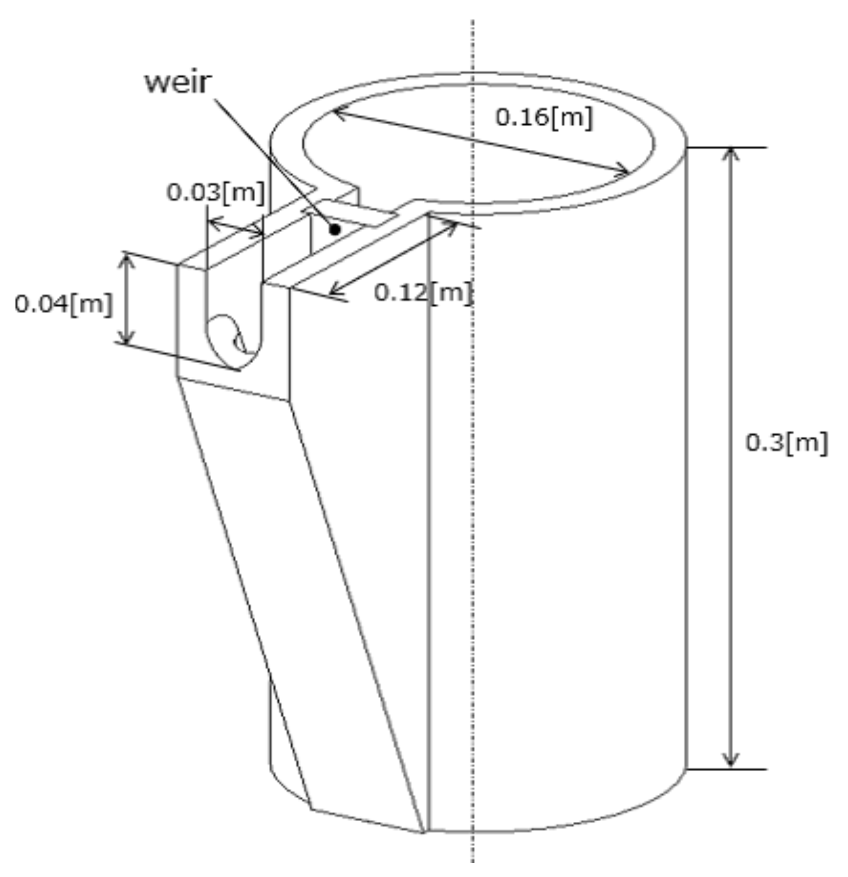
In this study, we used the tilting-ladle-type automatic pouring machine, as shown in Figure 2. The pouring machine’s ladle can be transferred to the Y- and Z-axes by the ball-screw mechanisms and the DC servo motors. The DC servo motor can also tilt the ladle on the -axis. A velocity control mode control all DC servo motors. The maximum velocities of Y and Z-axes are 0.775 and 0.387 m/s with motion ranges of 0 to 0.32 m and 0 to 0.52 m, respectively. The maximum angular velocity of -axis is 371.5 deg/s with a motion range 0–90 deg. Moreover, the rotary encoders installed into the servomotors measure the ladle’s position and tilting angle on the Y-, Z-, and -axes. The load cells installed on the automatic pouring machine’s base can measure the liquid’s weight flowing out of the ladle. The cylindrical-shaped ladle (Figure 3) used in this study has a weir to prevent entrainment of the slag floating on the liquid surface when dealing with molten metal. Therefore, this is similar to the ladle shape used in a realistic environment. For safety reasons, we used water as the target liquid.
In the previous study [24], a visible camera was used for measuring the liquid level in the sprue cup of the mold, and water was poured in the experimental verification. However, it is difficult to apply the visible camera in the practical pouring control system because high temperature molten iron glows, and fume and dust are present in the pouring environment. On the other hand, the rotary encoders and the load cells have been installed in most practical automatic pouring machines. Therefore, we constructed the pouring flow rate control system using the rotary encoders and the load cells.
3. Mathematical Model of Pouring Process
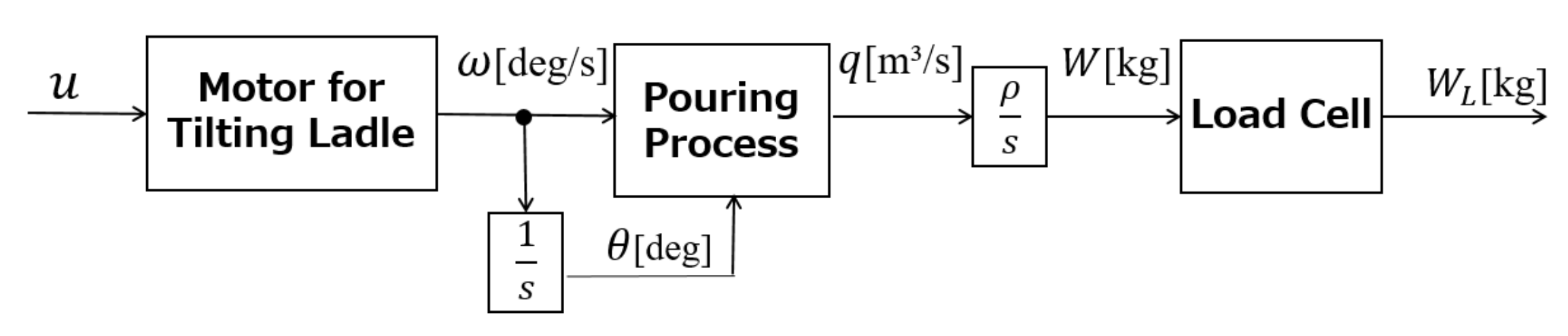
Figure 4 shows the pouring process’ block diagram used in the automatic pouring machine. The input command is given to the motor for tiling the ladle, and the ladle is tilted. Through the pouring process, the liquid flows out of the ladle. The load cell measures the liquid’s weight flowing out of the ladle.
3.1. Motor Model
The servo motor for tilting the ladle is controlled by a velocity feedback control. Therefore, the angular velocity of tilting ladle follows the input command given to the amplifier of the servo motor system. As the input command u to the motor, the ladle’s angular velocity deg/s and the tilting angle deg of the motor model can be represented simply as
where is the motor’s time constant and is the gain constant. In this study, the time constant is = 0.022 s, and the gain constant is = 0.980 deg/s.
3.2. Pouring Process Model
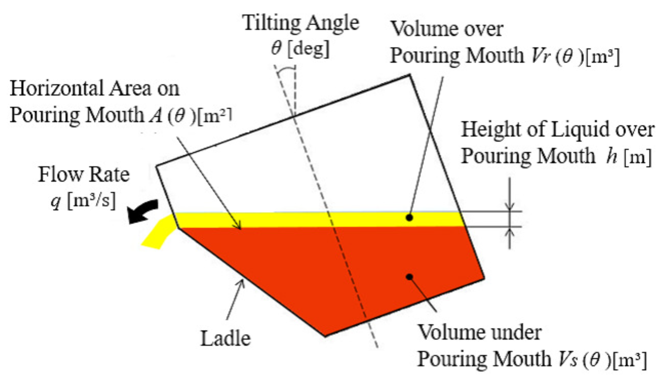
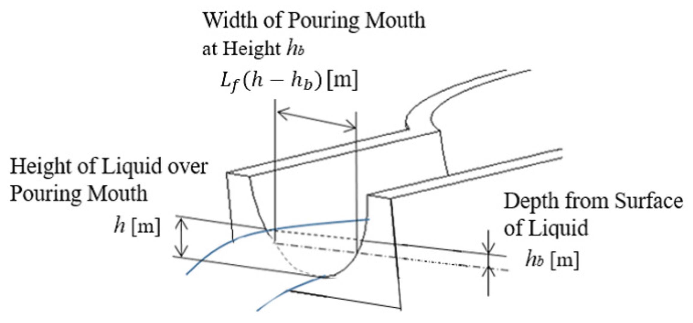
Figure 5 and Figure 6 show the liquid’s cross section in the ladle and the pouring mouth’s shape, respectively. In Figure 5, the liquid’s volume under the pouring mouth is m, the liquid’s volume over the pouring mouth is m, the liquid’s height over the pouring mouth is h m, the ladle’s tilting angle is deg, the tilting angle’s angular velocity is deg/s, and the outflow liquid’s flow rate from the ladle is q m/s. In Figure 6, the liquid depth from the liquid surface is m, and the pouring mouth’s width at the liquid height is m.
The liquid’s volume balance equation over the pouring mouth is
The relationship between the liquid height h and the pouring flow rate q using Bernoulli’s theorem is
where c is the flow rate coefficient, which can be identified by fitting the outflow liquid’s weight in the simulation using the model to that in the experiment. The liquid volumes and can be obtained from the ladle shape. The volume depends on the ladle’s tilting angle ; thus, its time derivative can be represented as
The volume depends on the tilting angle and the liquid height h in the liquid volume ; thus, the time derivative of can be represented as
The pouring process model can be represented as follows by substituting Equations (5) and (6) into Equation (3):
where is the ladle’s tilting angle at the start of the outflow liquid from the ladle.
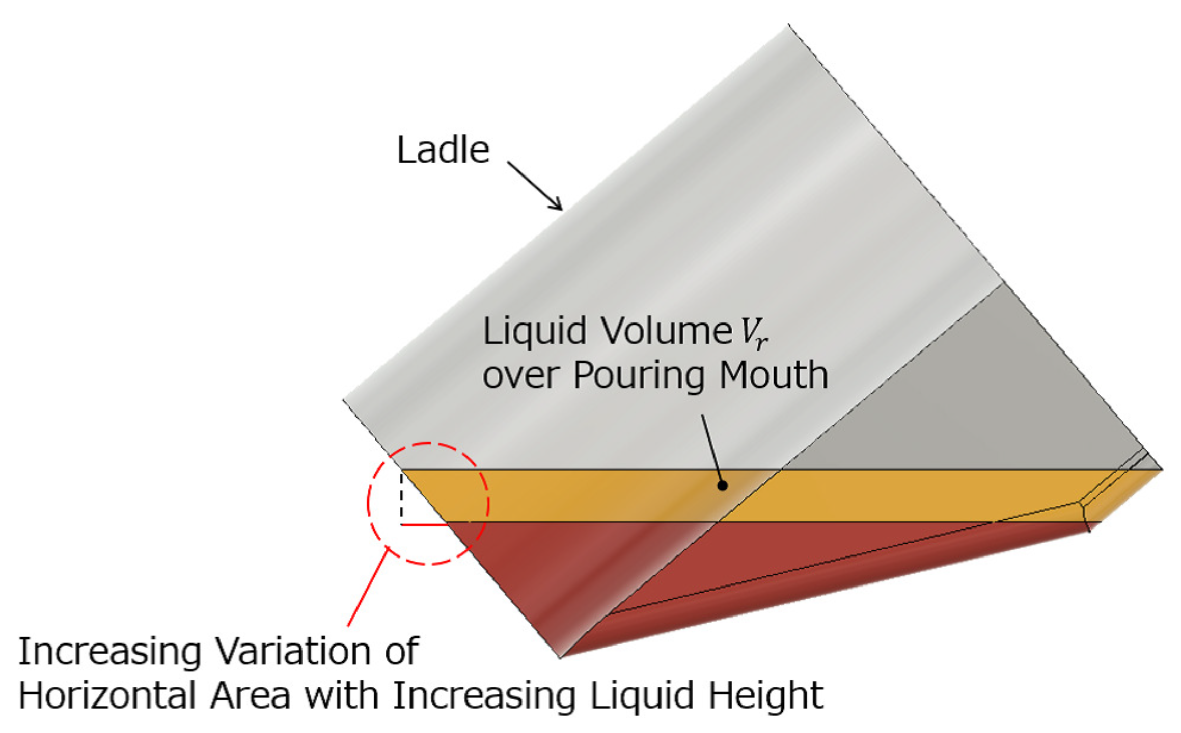
In the conventional pouring process model [12,22,23,24,25], it was assumed that an area variation with the liquid height h in the liquid volume is small. Therefore, derivative of liquid volume with respect to the liquid height h can be approximated to the upper surface area of the liquid in the ladle as
However, Figure 7 shows that the area variation with the liquid height h in the liquid volume becomes large in the ladle’s large tilting angle. Therefore, by this approximation, the accuracy of the conventional pouring process model was degraded with the increasing ladle’s tilting angle. The proposed pouring process model’s accuracy can be maintained even with the ladle’s large tilting angle because the derivative can be represented faithfully in the proposed pouring process model shown in Equation (7).
3.3. Load Cell Model
The relationship between the outflow liquid’s weight W kg from the ladle and the flow rate q is shown as follows:
where kg/m is the liquid density. The load cells installed at the automatic pouring machine’s bottom can measure the outflow liquid’s weight. The first-order lag system shows the load cell’s dynamic characteristics:
where kg is the outflow liquid’s weight measured by the load cell, and s is the load cell’s time constant.
4. Pouring Flow Rate Control System
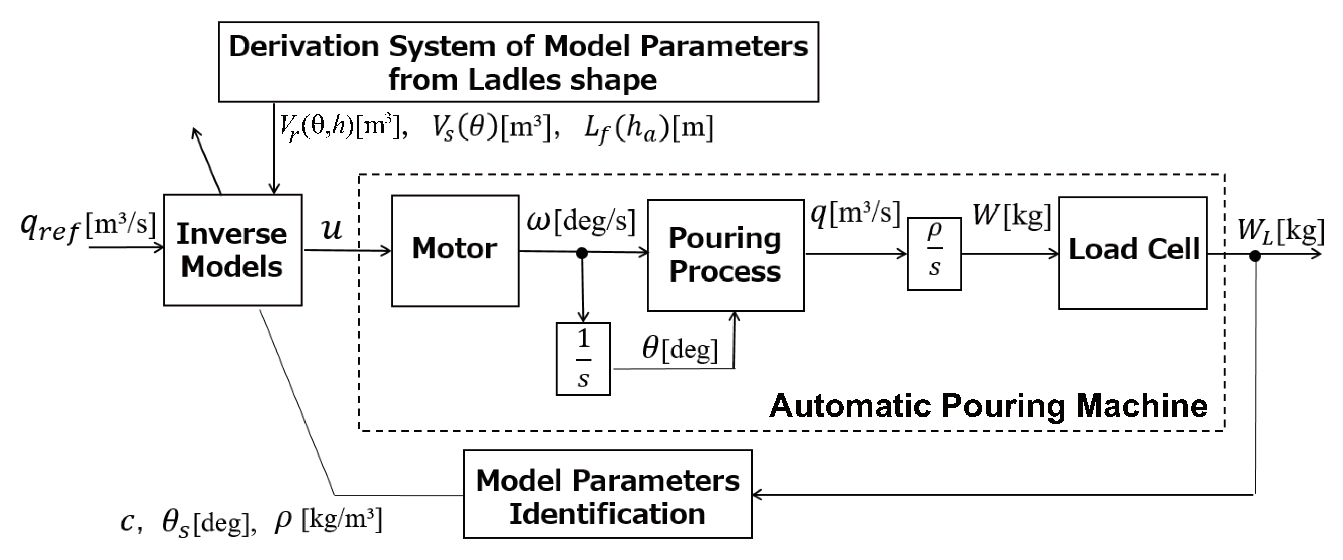
Figure 8 shows the block diagram of the proposed pouring control system. This is the feedforward control consisting of the inverse models of the pouring process and the motor. The input command u can be derived from the inverse models of the pouring process and the motor to realize the desired pouring flow rate m/s. The model-based control system requires obtaining the model parameters from the ladle shape and the pouring condition. The model parameters’ derivation system from the ladle and the model parameters identification, respectively, derive the model parameters obtained from the ladle shape and the pouring condition, as shown in Figure 8.
4.1. Feedforward Control Using Inverse Dynamics of Pouring Process and Motor
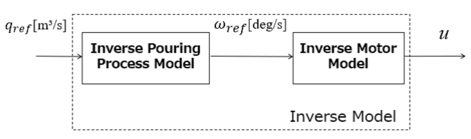
Figure 9 shows the block diagram of the proposed feedforward control. The motor’s inverse model for tilting the ladle can be derived as follows:
where deg/s represents the tilting angular velocity that realizes the desired flow rate pattern. The pouring process’ inverse model can also be derived from Equations (4) and (7) as follows:
where is the reference liquid height, which realizes the desired flow rate pattern. Equation (13) is the inverse function of Equation (4).
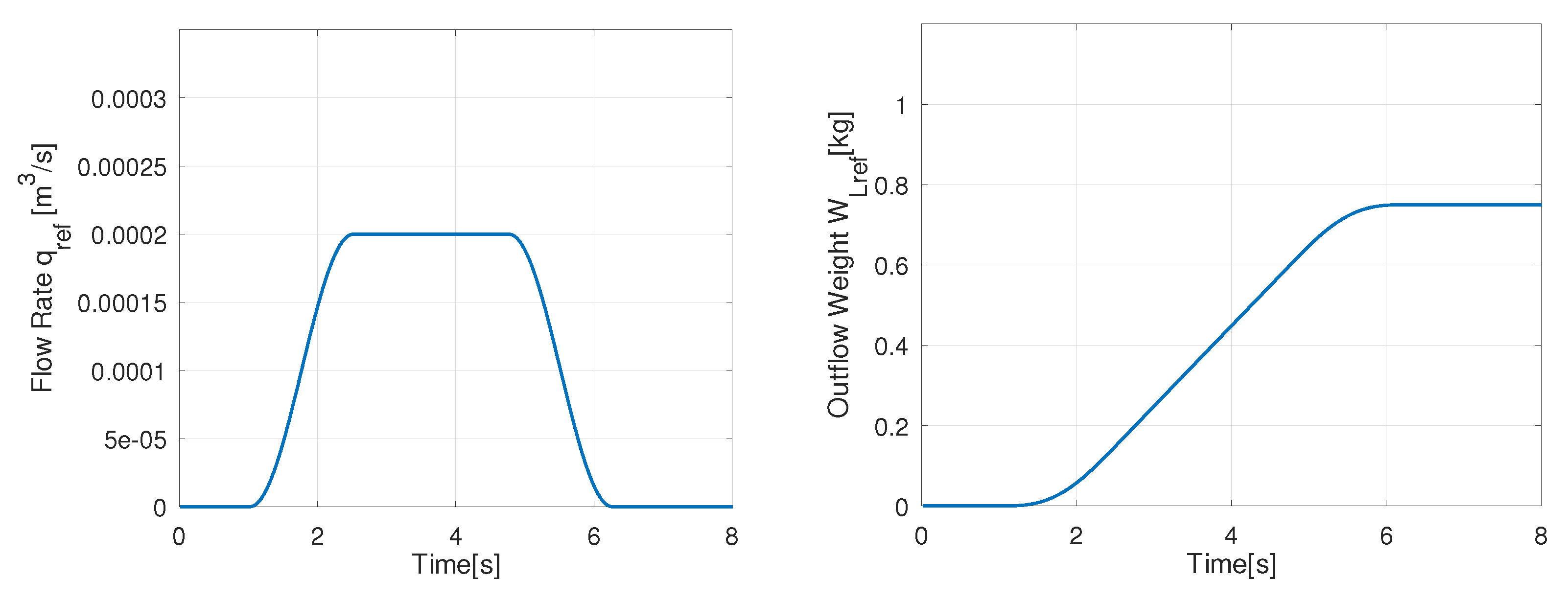
In the feedforward control with Equations (11)–(13), the desired flow rate pattern should be satisfied with a twice differentiable function. Here, we trigonometrically designed the desired flow rate pattern as follows:
where is the transient time to or from the steady flow rate , and is the time to maintain the steady flow rate. Figure 10 shows the desired flow rate pattern and the reference weight of the outflow liquid. The reference weight can be derived by substituting the desired flow rate pattern into Equations (9) and (10). In Figure 10, we give the parameters as m/s, s and s. Equation (14) is one of the simple flow rate patterns used in the automatic pouring machine.
4.2. Derivation System of Model Parameters from Ladle Shape
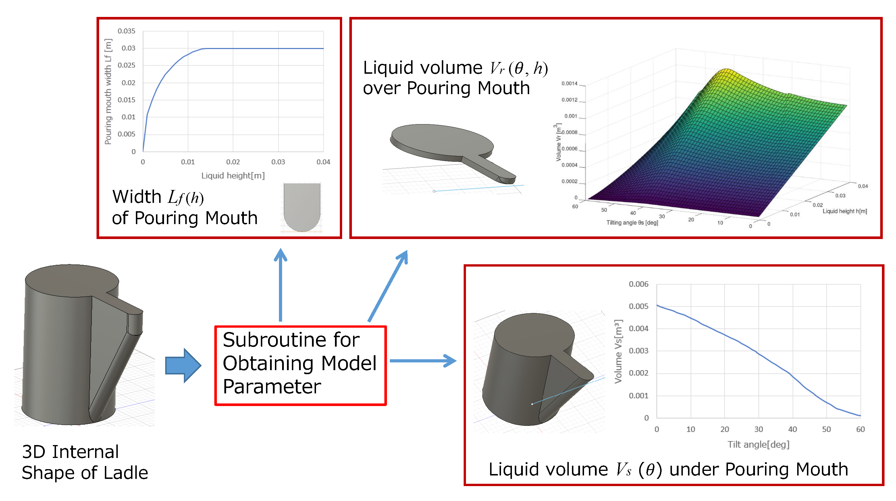
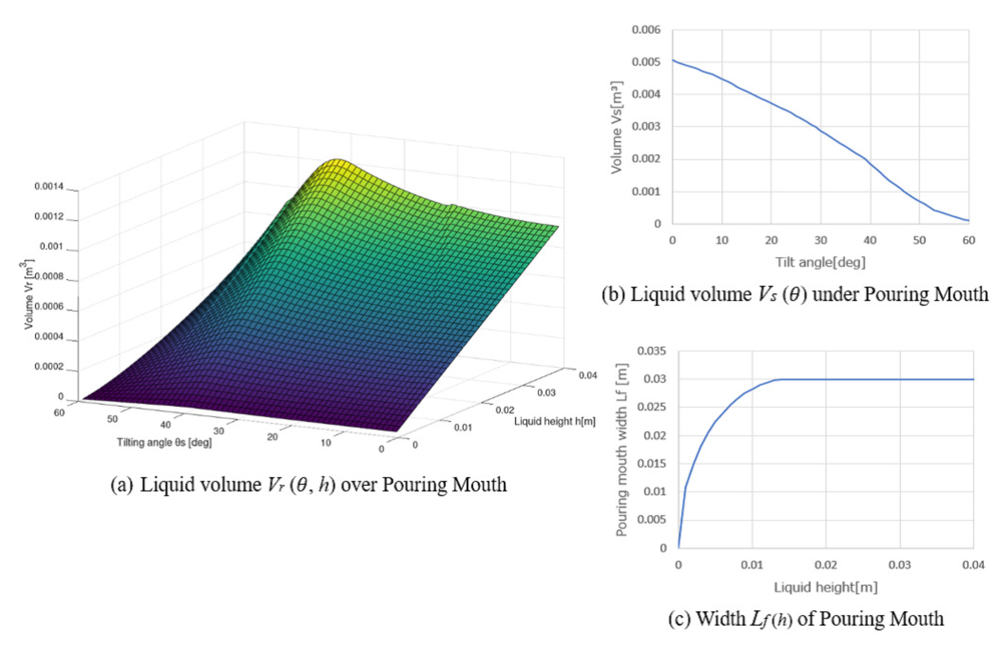
For designing the proposed pouring control system, it is required to obtain the model parameters from the ladle shape: (i) the liquid volume over the pouring mouth, (ii) the liquid volume under the pouring mouth, and (iii) the pouring mouth’s width . However, it is difficult to analytically calculate these model parameters because of the complication with the liquid shape with tilting the ladle. Furthermore, the ladle shape is different because of its dependency on the actual casting plant used. To apply the proposed pouring control system to the practical automatic pouring machines, we need to obtain quickly and systematically these model parameters from the applied ladle shape. Therefore, we proposed the derivation system of the model parameters from the ladle shape. It is the subroutine in the 3D-CAD in which the model parameters , , and are derived automatically from the ladle’s 3D internal shape. Here, we can instantaneously obtain these model parameters because we have the ladle’s 3D data, as shown in Figure 11. Figure 12 shows the obtained model parameters from the ladle shape. The sampling intervals of the liquid height h and the tilting angle are m and deg, respectively. Figure 12a shows the liquid volume over the pouring mouth, Figure 12b shows the liquid volume under the pouring mouth, and Figure 12c shows the pouring mouth’s width . We used the model parameters and with the differential forms in the proposed pouring control system. The differential forms of the model parameters are approximated as
where i and j are the index numbers of the vectors and h, respectively. In the proposed control system, the pouring process model’s accuracy is increased with a decrease in the sampling intervals and .
4.3. Online Model Parameters Identification
To design the proposed pouring control system, we need to obtain the following model parameters: (i) the ladle’s tilting angle deg at the start of the outflow liquid from the ladle, (ii) the flow rate coefficient c, and (iii) the liquid density . Here, we identified these model parameters online from the measured data in the pouring machine. Tsuji and Noda [25] identified these model parameters by minimizing the cost function:
where is the vector of the variables as . and are the outflow liquid’s weights measured by the load cell in the experiments and the simulation, respectively. t is the vector of the time as . They performed the parameters identification in Equation (15) by the downhill simplex method [26]. The downhill simplex method can optimize multidimensional variables without depending on the cost function’s derivative. However, the convergence speed becomes slower than other optimization methods because this method needs many operations [27]. The model parameters identification should be completed within the interval between each pouring motion. Practically, it is desired to identify the model parameters within 10 s. The cost function shown in Equation (16) is sensitive to the variation of the tilting angle . However, it is insensitive to the variations of the flow rate coefficient c and the liquid density . Therefore, we proposed the heuristic approach of the model parameters identification in the pouring control system. As a first step, only the tilting angle is identified by the following optimization:
We performed this optimization by the golden section method. As the next step, the flow rate coefficient c and the liquid density are identified by the following optimization:
We performed this optimization by the Gauss–Newton method. The two-step optimizations with the golden section method and Gauss–Newton method can quickly identify the model parameters , c, and .
4.4. Updating Controller’s Parameters
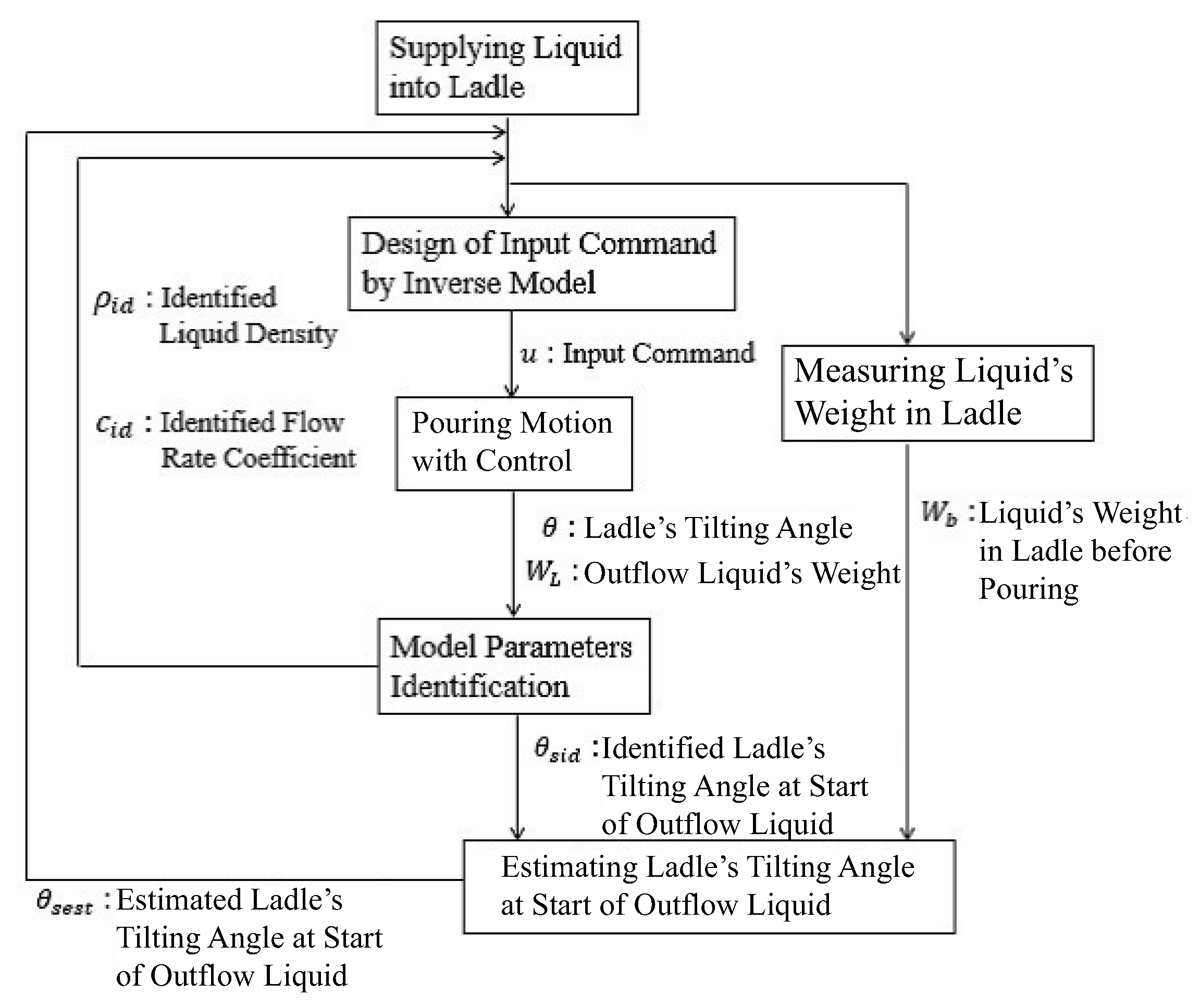
Figure 13 shows the procedure of updating the controller’s parameters. The inverse model designs the input command with the initial model parameters. After the pouring motion with the feedforward control, the proposed approach identified the model parameters , c, and . Then, the flow rate coefficient and the liquid density in the controller are updated to the identified parameters for each pouring. The ladle’s tilting angle at the start of the outflow liquid is stored with the liquid’s weight kg in the ladle before pouring. Here, the inverse function of the liquid volume under the pouring mouth can derive the tilting angle analytically:
However, the actual tilting angle has the uncertainties caused by the liquid’s surface tension, error in the ladle’s geometry, and so on. Thus, we compensated the analytical tilting angle by the least-squares method with the identified tilting angles stored in the control system as
where a is the slope and b is the intercept. Before the next pouring motion, the ladle’s tilting angle at the start of the outflow liquid can be estimated by Equations (21)–(23). Then, the tilting angle in the controller can be updated to the estimated tilting angle .
4.5. Reference Function of Model Parameters Using a Look-Up Table for Fast Model Parameters Identification
In the pouring process model, the model parameters , , and are varied in response to the tilting angle and the liquid height h. Tsuji and Noda [25] referred to the model parameters by an interpolation method in the control system. To refer quickly to these model parameters, we used the look-up table in this study. In this approach, the element number in these model parameters are obtained as
where and are the sampling intervals in these model parameters, and and are the minimum tilting angle and the liquid height, respectively. The element numbers are substituted into the model parameters matrix and vectors and in the control system. Applying this approach, we can improve the accuracy of these model parameters by decreasing the sampling intervals.
Tsuji and Noda [25] had difficulty decreasing the sampling intervals because of the manual operation in deriving these model parameters from the ladle shape. Therefore, using the model parameters’ derivation system from the ladle shape shown in Section 4.2, we can easily decrease the sampling intervals and quickly and precisely obtain the model parameters.
5. Experimental Verification
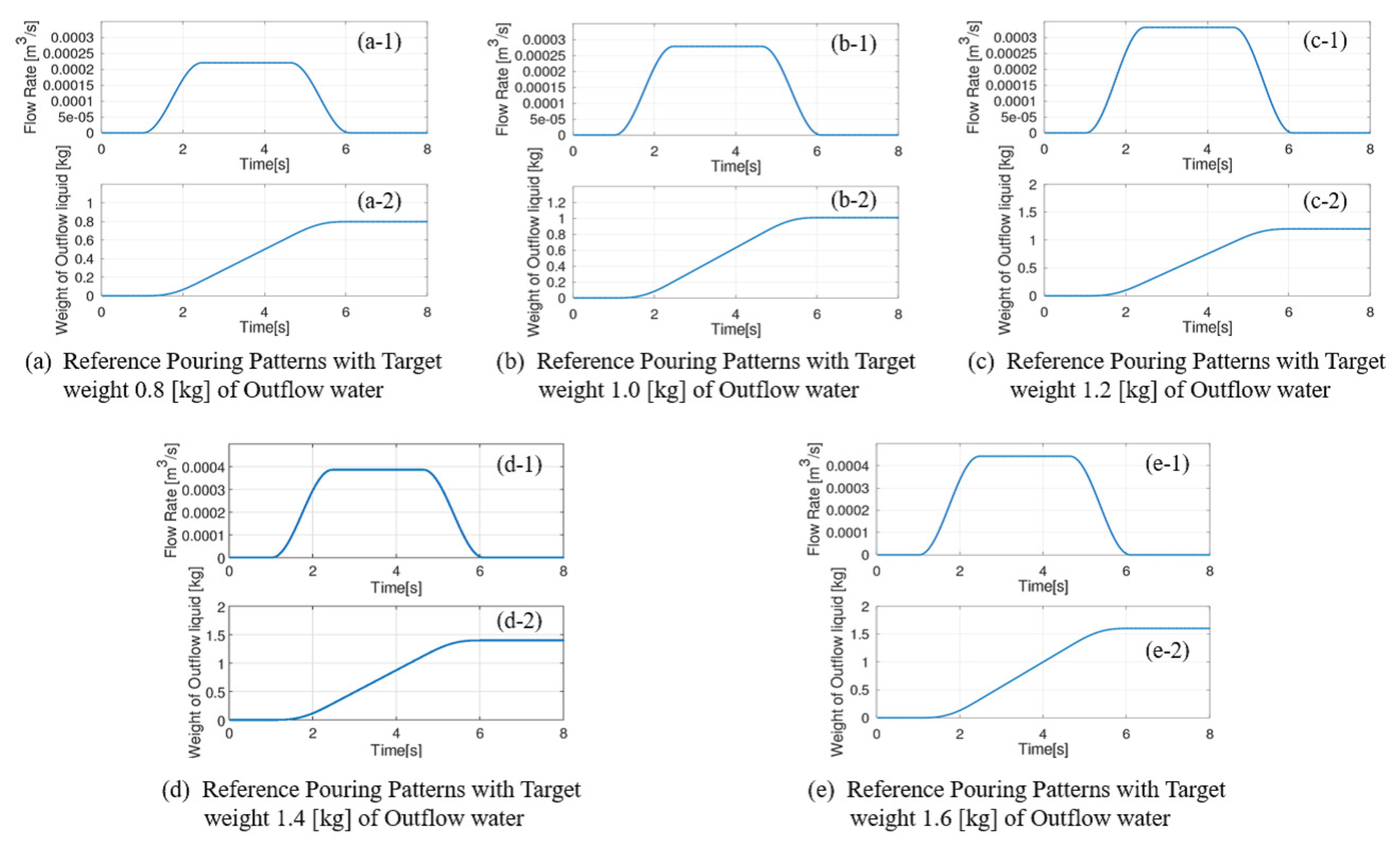
We verified the proposed pouring flow rate control system’s efficacy using the tilting-ladle-type automatic pouring machine in our laboratory, as shown in Figure 2. The water in the ladle is poured intermittently with five pouring patterns in the experiments, as shown in Figure 14. The outflow liquid’s flow rate and weight in the first pouring pattern with the target weight of 0.8 kg of the outflow water are shown in Figure 14a. Those with the target weights of 1.0 kg and 1.2 kg are shown in Figure 14b,c, respectively. Similarly, those with the target weights of 1.4 kg and 1.6 kg are shown in Figure 14d,e, respectively.
In the first trial experiments, the 4.2 kg water is supplied into the ladle before pouring. After that, the pouring motions with the three pouring patterns shown in Figure 14a–c are performed sequentially. In the second trial experiments, 3.8 kg water is supplied into the ladle, and the pouring motions with the two pouring patterns shown in Figure 14d,e are also performed.
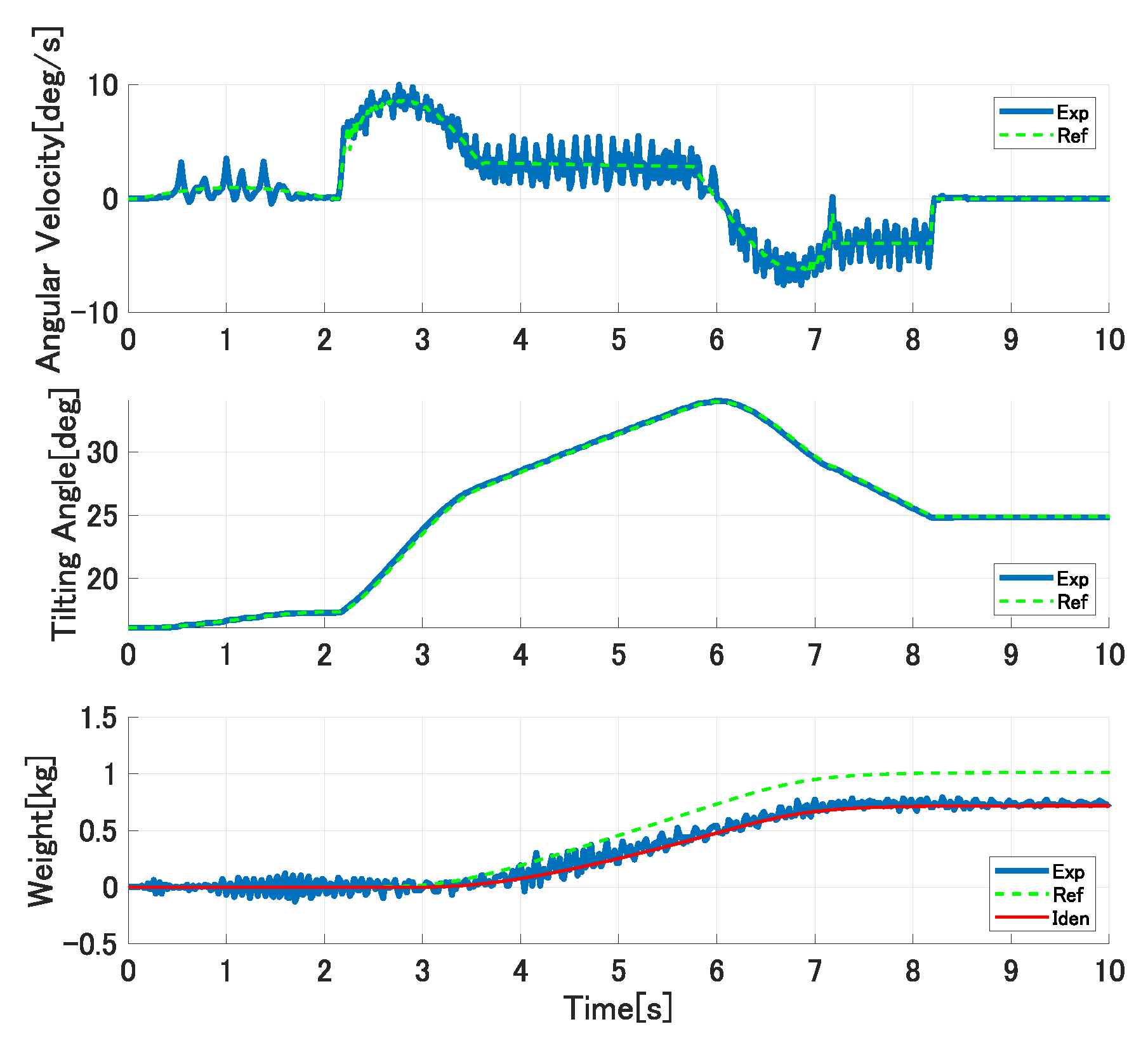
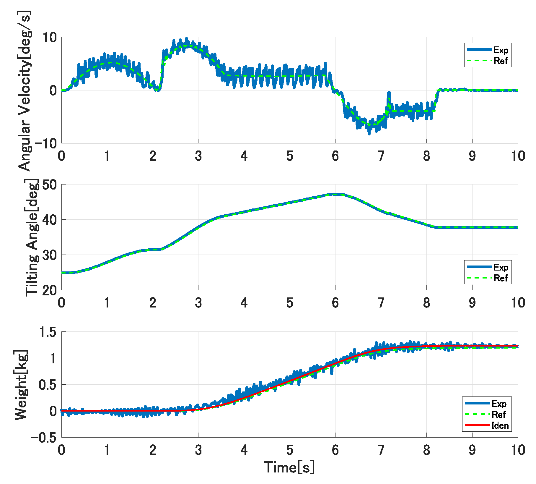
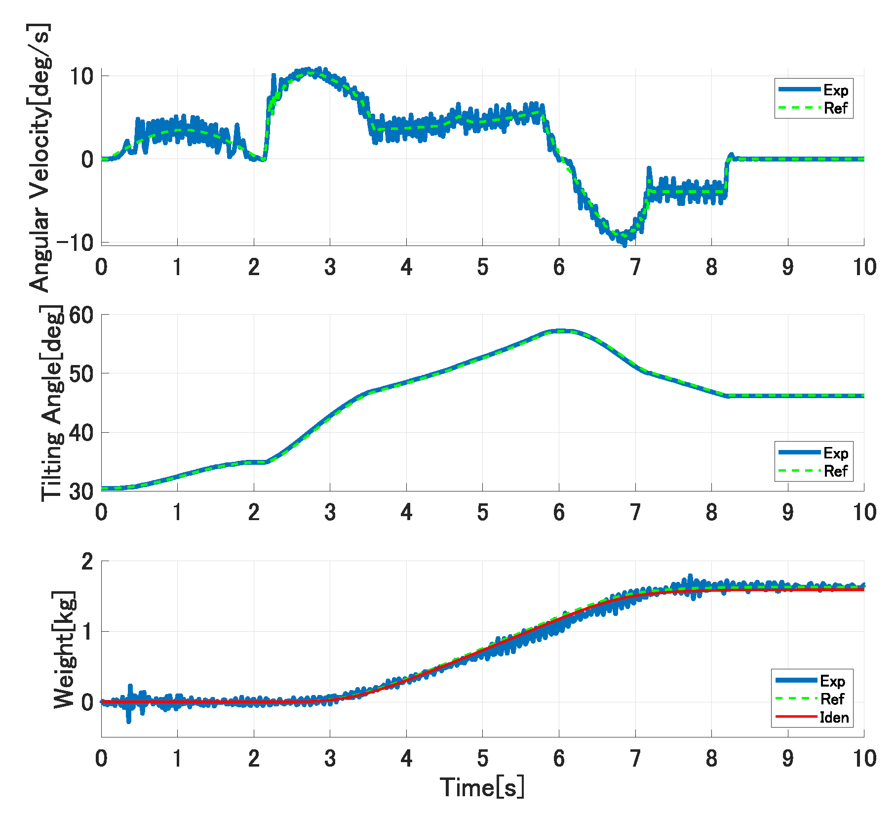
Figure 15, Figure 16 and Figure 17 show the experimental results in the first trial experiments of the proposed control system. The upper, middle, and lower graphs show the tilting ladle’s angular velocity, the ladle’s tilting angle, and the outflow liquid’s weight, respectively. The solid blue lines are the experimental results, the broken green lines are the references, and the solid red lines are the simulation results with the identified model parameters. In the first pouring, the flow rate coefficient and the water density kg/m are set as the controller’s parameters. The ladle’s tilting angle deg at the start of the outflow liquid is derived analytically from Equations (21) and (22) and set in the controller. In the second pouring, the proposed approach updates the flow rate coefficient and the liquid density. However, it cannot be updated because the single identified parameter cannot compensate the ladle’s tilting angle at the start of the outflow liquid. Therefore, the pouring motion’s accuracy cannot be improved. In the third pouring, all of the model parameters are updated. Therefore, the pouring control’s accuracy can be improved.
We performed the second trial experiments with different experimental conditions to the first trials. The pouring motion is performed with different ladle’s tilting angles at the start of the outflow liquid because the 3.8 kg water is supplied into the ladle before pouring. The proposed approach continuously updates the controller’s parameters. Figure 18 and Figure 19 show the experimental results of the second trial experiments, where the graphs and lines are illustrated similar to those in Figure 15. The online model parameters identification is maintained from the first trial to the second trial; therefore, even the first pouring in the second trial can be performed precisely. Moreover, the proposed model-based approach can improve the pouring control’s accuracy even in different pouring conditions.
Table 1 summarizes the proposed control system’s accuracy. We evaluated the accuracy of the outflow liquid’s weight in each pouring motion by the mean absolute errors between the experimental data and reference, and the experimental data and simulation data with identified model parameters. The mean absolute error between the experimental and reference weights can be represented as
where and are the outflow liquid’s experimental and reference weights, respectively, and is the data acquisition time. The mean absolute error between the experimental weight and the simulation weight can be represented similarly to Equation (24). By identifying the model parameters online and updating the control parameters, we can improve the pouring control’s accuracy.
Table 2 shows the model parameters used in each experiment and identified after the experiment and the processing times for the model parameters identification in the proposed and conventional approaches. In the conventional approach, the downhill simplex method [26] identified the model parameters as the ladle’s tilting angle at the start of the outflow liquid, the liquid density , and the flow rate coefficient c. The conventional approach takes s to identify the model parameters. Therefore, it is not easy to update the controller’s parameters within each pouring motion interval. The model parameters can be identified quickly in the proposed approach; it enables updating the controller’s parameters within the interval.
6. Conclusions
In this study, we proposed the model-based pouring flow rate control system. The model parameters are identified online, and the controller’s parameters are updated in the interval between each pouring motion. The following conclusions were drawn from the study:
- 1.
- In the pouring process model, the liquid volume over the pouring mouth was represented precisely for realizing the high-precision pouring in the ladle’s large tilting angle.
- 2.
- The model parameters for the ladle shape were derived systematically from the 3D-computer aided design (CAD) data through the subroutine.
- 3.
- The golden section method identified the ladle’s tilting angle at the start of the outflow liquid for quickly completing the model parameters identification. Similarly, the Gauss–Newton method identified the liquid density and the flow rate coefficient. Moreover, the look-up table was used in the reference function of the model parameters.
- 4.
- In the experiments using the tilting-ladle-type automatic pouring machine, the ladle’s water was poured precisely by updating the controller’s parameters after the proposed online model parameters identification.
In this study, we verified the proposed approach’s efficacy with the water as the target liquid. We will verify the proposed approach’s efficacy in the experiments with molten metal in our future work. The stability of the proposed flow rate control system based on the feedforward-type control using the inverse model of the pouring process was not discussed in this study. Therefore, we will discuss the stability of the proposed flow rate control system in our future work. Furthermore, we will attempt the design of the feedback flow rate control with online model parameters identification.
Author Contributions
Conceptualization, Y.N.; methodology, Y.N.; software, N.K.; validation, N.K.; formal analysis, Y.N. and N.K.; investigation, N.K.; resources, Y.N.; data curation, N.K.; writing—original draft preparation, N.K.; writing—review and editing, Y.N.; visualization, N.K.; supervision, Y.N.; project administration, Y.N.; funding acquisition, Y.N. All authors have read and agreed to the published version of the manuscript.
Funding
This research was funded by JSPS KAKENHI, Grant Number JP25420181, and JST Program of Start-up Incubation from Core Research, Grant Number STSC20003.
Institutional Review Board Statement
Not applicable.
Informed Consent Statement
Not applicable.
Conflicts of Interest
The authors declare no conflict of interest.
Abbreviations
The following abbreviations are used in this manuscript:
| CAE | Computer-Aided Engineering |
| DC | Direct Current |
| 3D-CAD | Three-Dimensional Computer-Aided Design system |
References
- Li, T.; Cao, Z.; Jin, J.; Zhang, Z. Control of Solidified Structure of Cast Metal by Imposing Electromagnetic Field. Mater. Trans. 2001, 42, 281–285. [Google Scholar] [CrossRef] [Green Version]
- Kubo, N.; Ishi, T.; Kubota, J.; Ikagawa, T. Numerical Simulation of Molten Steel Flow under a Magnetic Field with Argon Gas Bubbling in a Continuous Casting Mold. ISIJ Int. 2004, 44, 556–564. [Google Scholar] [CrossRef] [Green Version]
- Thomas, B.G. Review on Modeling and Simulation of Continuous Casting. Steel Res. Int. 2018, 89. [Google Scholar] [CrossRef]
- Vinarcik, E.J. High Integrity Die Casting Processes; John Wiley & Sons: Hoboken, NJ, USA, 2002. [Google Scholar]
- Karna, S.K.; Sahai, R. An Overview on Taguchi Method. Int. J. Eng. Math. Sci. IJEMS 2012, 1, 11–18. [Google Scholar]
- Syrcos, G.P. Die Casting Process Optimization Using Taguchi Methods. J. Mater. Process. Technol. 2003, 135, 68–74. [Google Scholar] [CrossRef]
- Apparao, K.C.; Birru, A.K. Optimization of Die Casting Process Based on Taguchi Approach. Mater. Today Proc. 2017, 4, 1852–1859. [Google Scholar] [CrossRef]
- Hussainy, S.F. Influence of Sand Molding Process Parameters on Product Quality of Al-Si Allay Casting—An ANOVA Approach. Int. J. Adv. Res. Sci. Eng. 2015, 4, 1751–1760. [Google Scholar]
- Lindsay, W. Automatic Pouring and Metal Distribution System. Foundry Trade J. 1983, 154, 151–176. [Google Scholar]
- Terashima, K. Problems of Casting Facilities. J. Jpn. Foundry Eng. Soc. 2001, 73, 39–40. (In Japanese) [Google Scholar]
- Lerner, Y.S. Ironing Out the Pouring Options. Mod. Cast. Mod. Cast. 2003, 93, 44. [Google Scholar]
- Noda, Y.; Nishida, T. Precision Analysis of Automatic Pouring Machines for the Casting Industry. Int. J. Autom. Technol. 2008, 2, 241–246. [Google Scholar] [CrossRef]
- Paranjape, S.; Chaubal, P.D. Automatic Pouring Systems Boosts Output at Mahindra Hinoday Ind. Metalworld 2010, 6, 24–27. [Google Scholar]
- Dubodelov, V.I.; Pogorsky, V.K.; Goryuk, M.S. Magnetodynamic Mixer-Batcher for Overheating and Pouring of Cast Iron. Key Eng. Mater. 2010, 457, 481–486. [Google Scholar] [CrossRef]
- Terashima, K.; Yano, K. Sloshing Analysis and Suppression Control of Tilting-type Automatic Pouring Machine. Control. Eng. Pract. 2001, 9, 607–620. [Google Scholar] [CrossRef]
- Ito, A.; Tasaki, R.; Suzuki, M.; Terashima, K. Analysis and Control of Pouring Ladle with Weir for Sloshing and Volume-Moving Vibration in Pouring Cut-Off Process. Int. J. Autom. Technol. 2017, 11, 645–656. [Google Scholar] [CrossRef]
- Yano, K.; Terashima, K. Supervisory Control of Automatic Pouring Machine. Control Eng. Pract. 2010, 9, 230–241. [Google Scholar] [CrossRef]
- Terashima, K.; Yano, K.; Sugimoto, Y. Modeling and Robust Control of Liquid Level in a Sprue Cup for Batch-type Casting Pouring Processes. In Proceedings of the IASTED International Conference on Intelligent Systems and Control, Salzburg, Austria, 25–27 June 2003; pp. 33–38. [Google Scholar]
- Terashima, K.; Yano, K.; Kaneko, M. Predictive Control of Flow Quantity and Sloshing-Suppression During Back-tilting of a Ladle for Batch-type Casting Pouring Processes. In Proceedings of the 13th IFAC Symposium on System Identification, Rotterdam, The Netherlands, 27–29 August 2003; pp. 507–512. [Google Scholar]
- Noda, Y.; Terashima, K. Modeling and Feedforward Flow Rate Control of Automatic Pouring System with Real Ladle. J. Robot. Mechatron. 2007, 19, 205–211. [Google Scholar] [CrossRef]
- Li, L.; Wang, C.; Wu, H. Research on Kinematics and Pouring Law of a Mobile Heavy Load Pouring Robot. Math. Probl. Eng. 2018. [Google Scholar] [CrossRef]
- Sueki, Y.; Noda, Y. Operational Assistance System with Direct Manipulation of Flow Rate and Falling Position of Outflow Liquid in Tilting-ladle-type Pouring Machine. In Proceedings of the 73rd World Foundry Congress, Cracow, Poland, 23–27 September 2018; pp. 325–326. [Google Scholar]
- Noda, Y.; Sueki, Y. Implementation and Experimental Verification of Flow Rate Control Based on Differential Flatness in a Tilting-Ladle-Type Automatic Pouring Machine. Appl. Sci. 2019, 9, 1978. [Google Scholar] [CrossRef] [Green Version]
- Ito, A.; Oetinger, P.; Tasaki, R.; Sawodny, O.; Terashima, K. Visual Nonlinear Feedback Control of Liquid Level in Mold Sprue Cup by Cascude System with Flow Rate Control for Tilting-Ladle-Type Automatic Pouring System. Mater. Sci. Forum 2018, 925, 483–490. [Google Scholar] [CrossRef]
- Tsuji, T.; Noda, Y. High-precision Pouring Control Using Online Model Parameters Identification in Automatic Pouring Robot with Cylindrical Ladle. In Proceedings of the 2014 IEEE International Conference on Systems, Man, and Cybernetics, San Diego, CA, USA, 5–8 October 2014; pp. 2593–2598. [Google Scholar]
- Nelder, J.A.; Mead, R. A Simplex Method for Function Minimization. Comput. J. 1965, 7, 308–313. [Google Scholar] [CrossRef]
- Koshel, R.J. Enhancement of the Downhill Simplex Method of Optimization. In Proceedings of the International Optical Design Conference, Tucson, AZ, USA, 3–5 June 2002. [Google Scholar]
- Stakhov, A.P. The golden section in the measurement theory. Comput. Math. Appl. 1989, 17, 613–638. [Google Scholar] [CrossRef] [Green Version]
- Kiefer, J. The sequential Minimax Search for a Maximum. Proc. Am. Math. Soc. 1953, 4, 502–506. [Google Scholar] [CrossRef]
- Wedderburn, R.W.M. Quasi-Likelihood Functions, Generalized Linear Models, and the Gauss-Newton Method. Biometrika 1974, 61, 439–447. [Google Scholar]
- Diehl, M.; Messerer, F. Local Convergence of Generalized Gauss-Newton and Sequential Convex Programming. In Proceedings of the IEEE 58th Conference on Decision and Control, Nice, France, 11–13 December 2019; pp. 3942–3947. [Google Scholar]
Figure 1.
Tilting-ladle-type automatic pouring machine.

Figure 2.
Tilting-ladle-type automatic pouring machine in laboratory.

Figure 3.
Ladle geometry.

Figure 4.
Block diagram of automatic pouring process.

Figure 5.
Cross section of pouring process.

Figure 6.
Parameters on pouring mouth.

Figure 7.
Internal liquid shape in ladle with large tilting angle.

Figure 8.
Block diagram of proposed pouring flow rate control system.

Figure 9.
Block diagram of feedforward control with inverse model.

Figure 10.
Desired pouring patterns.

Figure 11.
Derivation system of model parameters from ladle shape.

Figure 12.
Model parameters obtained from ladle shape shown in Figure 3.
Figure 12.
Model parameters obtained from ladle shape shown in Figure 3.

Figure 13.
Flowchart of updating controller’s parameters.

Figure 14.
Pouring Patterns as Reference Input in Experiments.

Figure 15.
Experimental results of first pouring in first trial experiments.

Figure 16.
Experimental results of second pouring in first trial experiments.

Figure 17.
Experimental results of third pouring in first trial experiments.

Figure 18.
Experimental results of forth pouring in second trial experiments.

Figure 19.
Experimental results of fifth pouring in second trial experiments.


Table 1.
Accuracy Evaluation by mean absolute errors in weights of outflow liquid.
| Number of Pouring | Target Weight [kg] | Mean Absolute Error, [kg] | Mean Absolute Error, [kg] |
|---|---|---|---|
| 1-1 | 0.80 | 0.1347 | 0.0527 |
| 1-2 | 1.00 | 0.1553 | 0.0397 |
| 1-3 | 1.20 | 0.0523 | 0.0420 |
| 2-4 | 1.40 | 0.0640 | 0.0386 |
| 2-5 | 1.60 | 0.0498 | 0.0490 |
Table 2.
Parameters in controller and processing times in proposed and conventional approaches.
| Number of Pouring | Parameter Used in Experiment | Identified Parameters | Processing Time in Proposed Approach [s] | Processing Time in Conventional Approach (Downhill Simplex Method) [s] | ||||
|---|---|---|---|---|---|---|---|---|
| c | c | |||||||
| 1-1 | 10.0 | 1000 | 0.80 | 13.3 | 999.8 | 0.76 | 2.69 | 55.38 |
| 1-2 | 17.3 | 999.8 | 0.76 | 21.0 | 996.9 | 0.77 | 2.59 | 50.18 |
| 1-3 | 31.5 | 996.9 | 0.77 | 31.0 | 995.1 | 0.76 | 2.38 | 60.54 |
| 2-4 | 19.7 | 995.1 | 0.76 | 20.7 | 993.8 | 0.74 | 3.01 | 79.57 |
| 2-5 | 34.9 | 993.8 | 0.74 | 35.2 | 991.1 | 0.72 | 3.65 | 78.08 |
Publisher’s Note: MDPI stays neutral with regard to jurisdictional claims in published maps and institutional affiliations. |
© 2021 by the authors. Licensee MDPI, Basel, Switzerland. This article is an open access article distributed under the terms and conditions of the Creative Commons Attribution (CC BY) license (http://creativecommons.org/licenses/by/4.0/).
Share and Cite
MDPI and ACS Style
Kabasawa, N.; Noda, Y. Model-Based Flow Rate Control with Online Model Parameters Identification in Automatic Pouring Machine. Robotics 2021, 10, 39. https://0-doi-org.brum.beds.ac.uk/10.3390/robotics10010039
AMA Style
Kabasawa N, Noda Y. Model-Based Flow Rate Control with Online Model Parameters Identification in Automatic Pouring Machine. Robotics. 2021; 10(1):39. https://0-doi-org.brum.beds.ac.uk/10.3390/robotics10010039
Chicago/Turabian StyleKabasawa, Nobutoshi, and Yoshiyuki Noda. 2021. "Model-Based Flow Rate Control with Online Model Parameters Identification in Automatic Pouring Machine" Robotics 10, no. 1: 39. https://0-doi-org.brum.beds.ac.uk/10.3390/robotics10010039
Note that from the first issue of 2016, this journal uses article numbers instead of page numbers. See further details here.