A Planar Parallel Device for Neurorehabilitation
by
 , , , , and
Jawad Yamine
1 ,
,
Alessio Prini
2,
Matteo Lavit Nicora
2 ,
,
Tito Dinon
2,
Hermes Giberti
3 and
Matteo Malosio
2,* 1
Politecnico di Milano, Via la Masa 1, 20156 Milano, Italy
2
Istituto di Sistemi e Tecnologie Industriali Intelligenti per il Manifatturiero Avanzato, Consiglio Nazionale delle Ricerche, via G. Previati 1/E, 23900 Lecco, Italy
3
Dipartimento di Ingegneria Industriale e dell’Informazione, Università di Pavia, Via ferrata 5, 27100 Pavia, Italy
*
Author to whom correspondence should be addressed.
Robotics 2020, 9(4), 104; https://0-doi-org.brum.beds.ac.uk/10.3390/robotics9040104
Submission received: 15 October 2020
/
Revised: 21 November 2020
/
Accepted: 27 November 2020
/
Published: 3 December 2020
(This article belongs to the Special Issue Kinematics and Robot Design III, KaRD2020)
Abstract
:The patient population needing physical rehabilitation in the upper extremity is constantly increasing. Robotic devices have the potential to address this problem, however most of the rehabilitation robots are technically advanced and mainly designed for clinical use. This paper presents the development of an affordable device for upper-limb neurorehabilitation designed for home use. The device is based on a 2-DOF five-bar parallel kinematic mechanism. The prototype has been designed so that it can be bound on one side of a table with a clamp. A kinematic optimization was performed on the length of the links of the manipulator in order to provide the optimum kinematic behaviour within the desired workspace. The mechanical structure was developed, and a 3D-printed prototype was assembled. The prototype embeds two single-point load cells to measure the force exchanged with the patient. Rehabilitation-specific control algorithms are described and tested. Finally, an experimental procedure is performed in order to validate the accuracy of the position measurements. The assessment confirms an acceptable level of performance with respect to the requirements of the application under analysis.
1. Introduction
Stroke is one of the main causes of long-term disability worldwide and the most common in Western countries [1]. The number of patients having difficulties in performing daily-living activities due to physical disabilities is constantly increasing, making the availability of therapists and caregivers more and more inadequate and, therefore, creating an unmet market need.
Robotic devices for neurorehabilitation have been widely investigated, developed and introduced in the market to offer a valid alternative to conventional therapy and fill the constantly growing gap between supply and demand [2,3]. Since the invention of the MIT-Manus [4], robot-assistance, force-feedback and force-based control are sought after features of neurorehabilitation devices [5], enabling them to sense the patient’s interaction with the robot, react accordingly and adapt the level of physical assistance provided. Most of the proposed robots are technically advanced, but are relatively expensive and designed for clinical settings, which makes it hard for patients to afford such treatment. There are also examples of commercial general-purpose industrial manipulators, properly equipped with force-based control algorithms, exploited in rehabilitation scenarios [6,7,8]. They can be very flexible and useful for testing purposes but, on the other side, they are inherently relatively expensive with respect to rehabilitation budget requirements.
Focusing on upper-limb rehabilitation, a number of low-cost rehabilitation devices are currently available, typically passive or passively gravity-balanced [9]. Nevertheless, the lack of actuation, of an assist-as-needed support and of haptic capabilities, preclude them to be effectively used by patients with low/medium motion capabilities. The development of low-cost rehabilitation devices also meets the need of low-income countries where the healthcare system is lacking and the medical personnel is insufficient. In these countries, where even hospitals cannot afford expensive mechanical devices, the challenge is to conceive and develop low-cost and easily-replicable systems for rehabilitation, as far as possible.
Some tabletop actuated devices have been specifically developed with the aim of satisfying economic and installation requirements in out-of-clinic environments. These solutions often rely on reduced complexity and optimized costs by limiting the number of degrees of freedom with respect to complex rehabilitation devices, such as exoskeletons [10,11,12], in order to partially meet the affordability requirements. However, strictly reducing the number of degrees of freedom of exoskeletons can sometimes lead to drawbacks. The authors of [13] developed an interesting elbow rehabilitation device; but, since the architecture is not supported or constrained to a fixed structure, the device weighs on the shoulder of the patient with a consequent lack of rehabilitation for that specific body part.
The large majority of tabletop devices are constituted by rigid links and joints. Nevertheless, it is worth to mention the existence of alternative solutions. CUBE is a tabletop cable-driven device enabling 3D-movements of the upper limb [14]. Despite its peculiar and interesting kinematic architecture, it does not provide a steady support for the hand in spatial movements since its end-effector is constrained only by two groups of three wires. MOTORE is an interesting mobile robot for upper-limb rehabilitation, but the need of resting completely the forearm on the device can constrain the upper arm excessively and lead to a high elevation angle of the elbow [15].
Alternative solutions can mobilize the upper arm for specific movements, but do not allow a wide movement of the upper limb, both in terms of shoulder and elbow. For instance, Nam et al. developed a portable device, capable of mobilizing the pronosupination of the forearm, unusual capability for tabletop devices [16]. However, its kinematic structure does not allow the rehabilitation of the upper limb in an extensive range of motion, since it does not provide any mobilization of the shoulder.
Moreover, planar movements are largely used for upper-limb neurorehabilitation and they represent the basis for interesting works such as the one proposed by Zadravec et al., in which a solution to model the planar movement trajectory formation [17] is suggested. By referring to articulated kinematic structures, it is possible to highlight a characteristic shared among different devices. The human body is inherently symmetric with respect to the sagittal plane. Nevertheless, several devices are characterized by a non-symmetric structure that could cause kinetostatic performance and manipulability ellipses to also be asymmetric with respect the sagittal plane. Asymmetrical kinematic structures produce asymmetrical shapes of the manipulability ellipsis, leading to an asymmetric kinetostatic behaviour for right-handed and left-handed patients. This is true for the kinematic structure of several rehabilitation devices, such as MIT-Manus [4], Braccio di Ferro [18] and NURSE [19].
Focusing on symmetrical kinetostatic behaviour with respect to the sagittal plane, some paradigmatic devices can be found. Some of them exploit Cartesian kinematic architectures, both serial and parallel. Wu et al. developed an admittance-controlled Cartesian serial kinematic architecture [20], while Zollo et al. proposed a planar orthogonal parallel rehabilitation device [21]. Both these devices are characterized by an inherent isotropic kinetostatic behaviour. However, in the opinion of the authors, such architectures are relatively cumbersome and complex and would not allow an effective commercial exploitation, especially in low-budget rehabilitation scenarios. An additional solution is provided by the H-MAN [22], a differential-based isotropic planar device for upper-limb rehabilitation. Although the authors consider its design outstanding, the goal of this work was to develop a device able to exploit extensively the range of motion of the upper limb, without leading to a relatively bulky structure. In these terms, the notable architecture of H-MAN would have resulted in a big and not straightforwardly portable device if properly scaled to allow large movements of the upper limb, mainly because of its Cartesian structure.
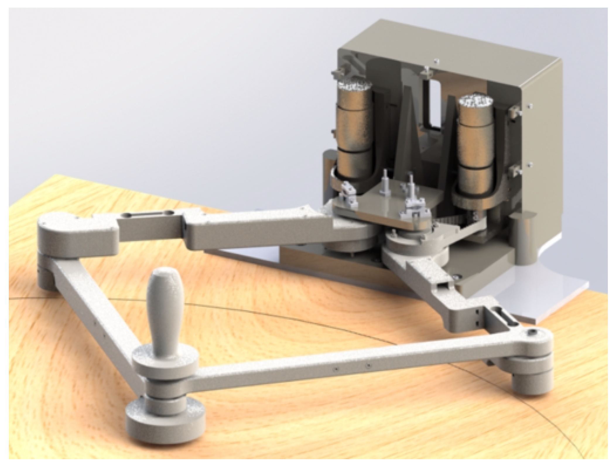
The aim of the present work was to present a rehabilitation device, namely PLANarm2, developed specifically to achieve an acceptable compromise in terms of (1) workspace symmetry with respect to the sagittal plane, (2) relatively large workspace, (3) portability and (4) affordability (Figure 1). The well-known 5R planar kinematic chain was considered a promising solution [23]. It is a matter of fact that this architecture has already been adopted to realize the haptic device developed by Klein et al. [24]. Starting from the parametric model of the 5R kinematics, link lengths of PLANarm2 have been optimized to have good kinematic performances in the large majority of its workspace, properly dimensioned to overlap the range of motion of the upper limb. Its symmetric kinematic structure is inherently characterized by a symmetrically distributed kinetostatic behaviour with respect to the sagittal plane. Moreover, in order to reduce the total cost of the device, it has been designed to be clamped quite easily on a standard table and to facilitate both portability and fast installation inside already furnished environments. As opposed to the device described in [24], which is characterized by a self-supported manipulandum, the PLANarm2 manipulandum slides on a table or an a desk, whose surface supports the gravitational load. The links of the parallel structure only transmit horizontal forces, limiting bending loads. This allowed the device to be realized by additive manufacturing techniques with plastic material, in line with the affordability requirement.
The paper is organized as follows: the kinematic architecture is presented in Section 2; the mechanical design and its optimization are described in Section 3; the main components of the prototype and a brief cost analysis are reported in Section 4; the control framework is presented in Section 5; results of an experimental assessment are outlined in Section 6; conclusions are drawn in Section 7.
2. Kinematics
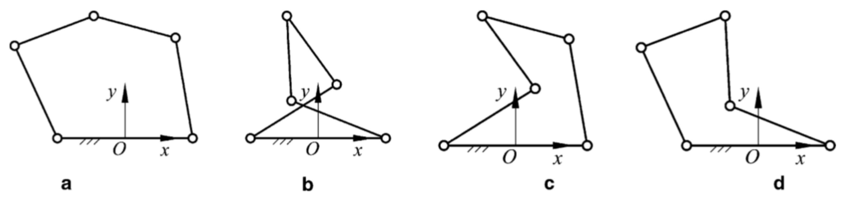
The forward and inverse kinematics presented in this section were developed to provide a less general but more efficient formulation than the one in [25]. The model proposed in the mentioned work provides the solution to the inverse kinematics problem for each of the four a possible configurations depicted in Figure 2. In addition, the forward kinematic problem leads to two solutions, one for the up-configuration and one for the down-configuration. In order to reduce the computational burden, the model presented in the following pages has been developed specifically for the configuration of interest, which is configuration (a) in the up-configuration.
2.1. Architecture
The device described in this paper is a 2-DOF parallel kinematic manipulator. It is characterized by a structure made up of four links and a fixed frame connected by five revolute joints. The main reason for the choice of this kind of closed-loop architecture was the possibility of placing both motors on a fixed base. Thanks to this solution, the robot is characterized by a relatively high stiffness and lower moving masses if compared to serial manipulators, therefore providing higher dynamic performances, a lighter structure and, potentially, better positioning accuracy.
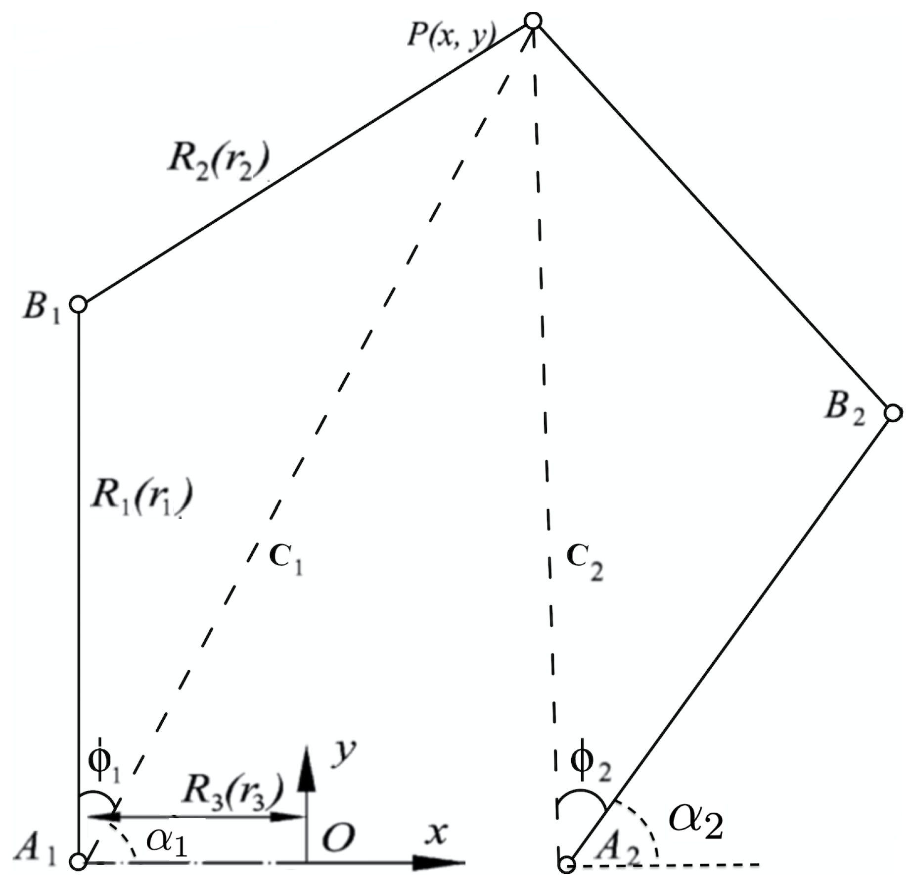
With reference to the generic planar parallel five-bar mechanism depicted in Figure 3, the end-effector is connected to the base by two legs, each of which consists of three revolute joints and two links. Joints and are connected to the base where they are actuated. The joints at the other end of each actuated link are denoted as and . A fixed global reference system is located in the midpoint of the segment with the y axis normal to and the x axis directed along . The mechanism is characterized by a symmetric structure where , and . The notation represents the link lengths with dimensions while represents dimensionless lengths of the links. Given:
One can obtain the three non-dimensional parameters:
It is important to stress the fact that such an architecture is characterized by four possible configurations and , as shown in Figure 2. However, only configuration will be considered in the scope of this paper. Moreover, on the basis of the singularity analysis done in [25], the following constraints must be applied:
- in order to avoid the uncertainty singularity where is extended.
- and in order to have a manipulator with a surrounded workspace
2.2. Inverse Kinematics
The joint variables are expressed as a function of the end-effector position using the following inverse kinematic equations:
where
2.3. Forward Kinematics
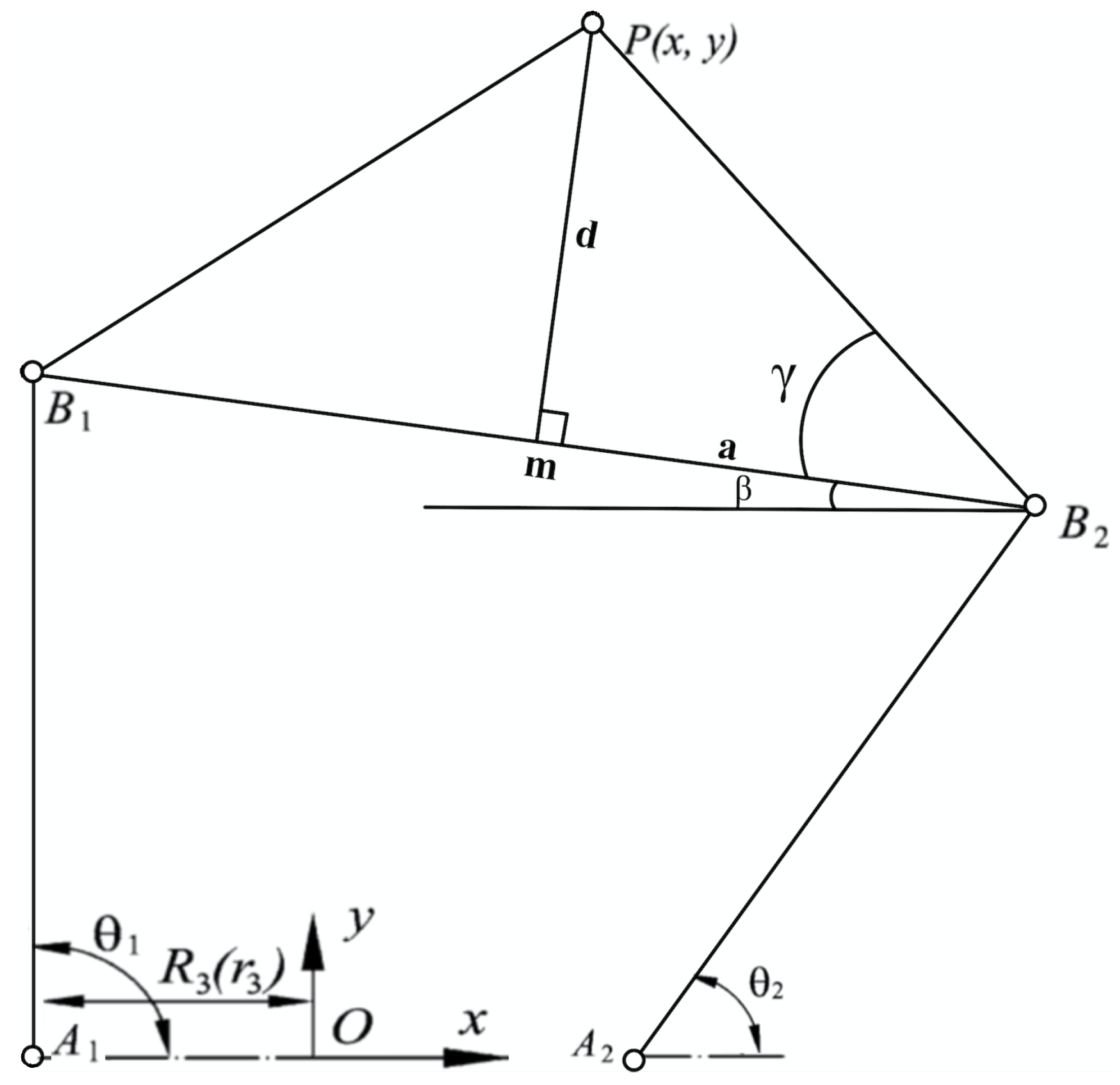
The forward kinematic relations are derived using the variables described in Figure 4. Regarding the notation, m is the midpoint of segment , is the angle between segment and the x-axis, d is the distance between the end-effector P and segment , a represents the distance from m to and, finally, is the angle between segment and .
The end-effector position can be calculated as:
where:
2.4. Jacobian
Differentiating Equation (6) with respect to time and rearranging the terms one can obtain:
where:
in which:
3. Mechanical Design
3.1. Workspace
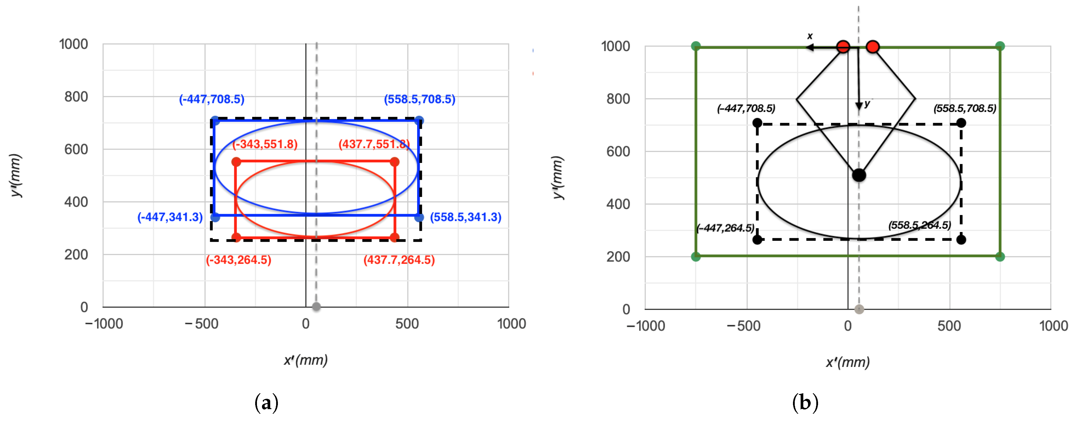
The theoretical reachable workspace for upper arm neurorehabilitation in Cartesian coordinates was defined in [26] through a transformation from articular to Cartesian space, performed using the direct kinematics of the human arm. The inclusive theoretical platform was defined as the union between the workspace defined for minimum limb lengths and the workspace defined for the maximum limb lengths. The resulting workspace is identified by an ellipse with centre c = [0, 513.5] mm, minor axis = 222 mm and major axis = 502.75 mm.
Since the population under study in [26] was right-handed, the authors of that research centred the reachable workspace at x = 55.75 mm. Consequently, the y-axis of PLANarm2 has been translated in order to have it aligned with the centre of the reachable workspace, as shown in Figure 5a. Since the manipulator is designed to be home based, it will be installed on a regular home table or desk. An average sized table is assumed to have a length of, at least, 1500 mm and a width of about 800 mm. Furthermore, the patient must be located at a distance of 200 mm away from the table, as shown in Figure 5b.
3.2. Kinematic Optimization
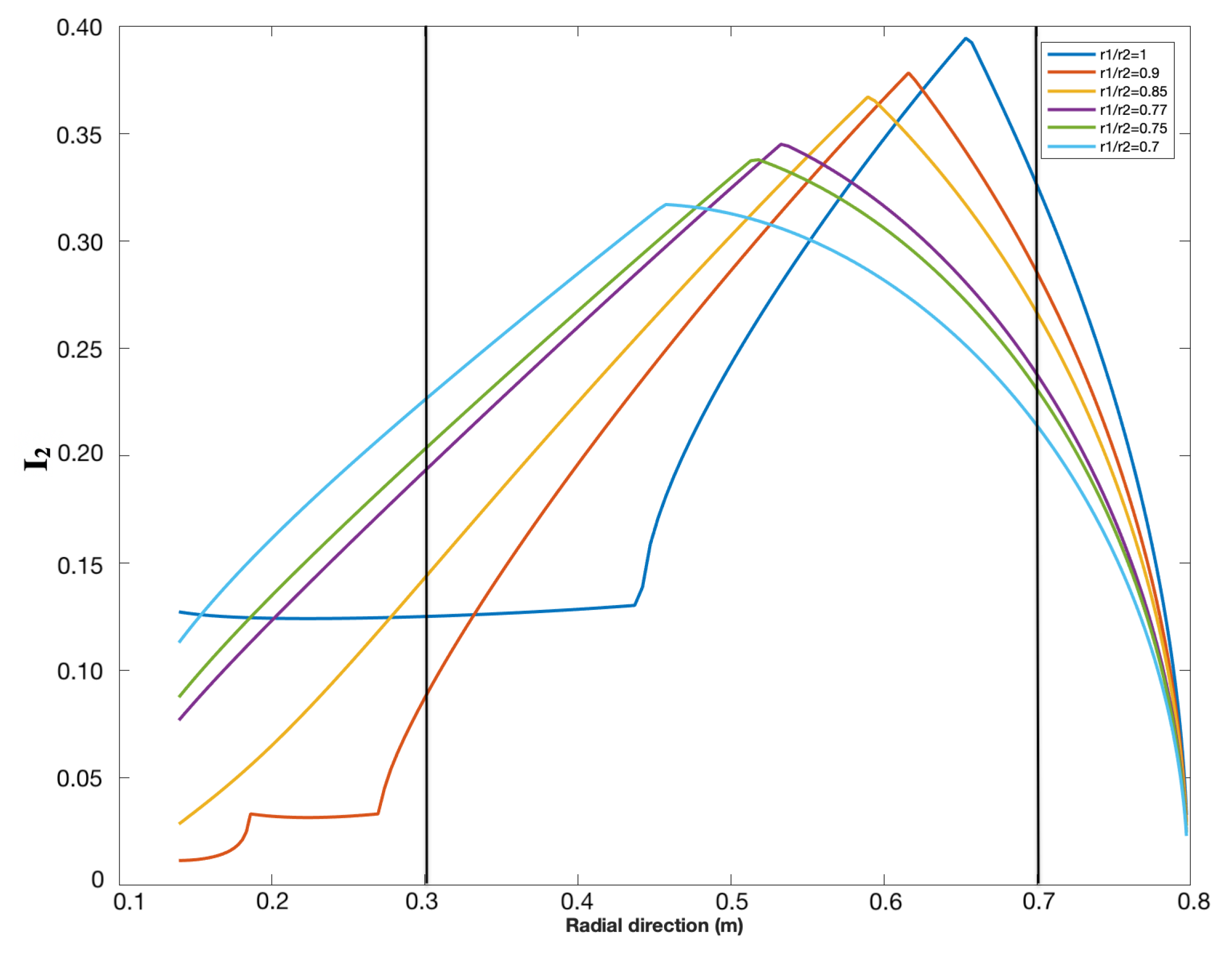
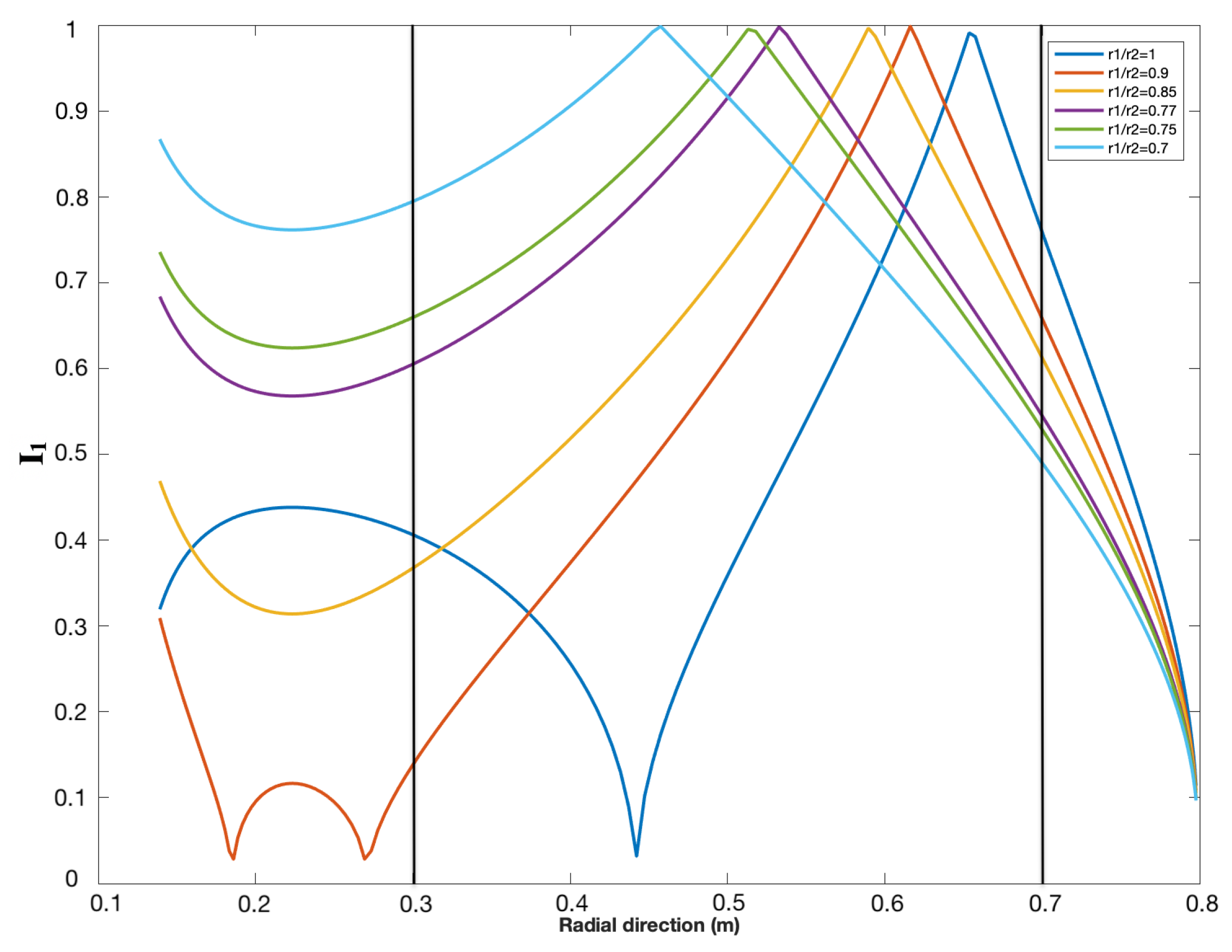
The link lengths have been optimized in order to provide the best kinetostatic performance. The lower is, the larger the theoretical workspace is [25]. The maximum workspace is obtained when the joints connected to the ground are coaxial (). However, due to mechanical constraints, the lowest possible value of was chosen to be equal to 45 mm. Based on the reachable workspace, it was sufficient to choose mm. Finally, in order to determine the values of and , the minimum stiffness and isotropy were optimized over the radial direction. Both indexes are radially symmetric [23] and therefore they are plotted against the y-direction in Figure 6 and Figure 7. The interval of interest is y = [300 mm, 700 mm], which includes the reachable workspace.
- : The minimum singular value (minimum stiffness)The index corresponding to the minimum singular value is defined as:The greater the minimum singular value, the greater the minimum rigidity of the machine. The minimum singular value was plotted against the radial direction of the manipulator for different ratios of and the results are shown in Figure 6.
- : Conditioning number (Isotropy)The conditioning number is a measure of the isotropy of the manipulator from the rigidity point of view. It is defined as the ratio between the maximum and minimum singular values of the Jacobian:The closer this ratio is to 1, the more consistent the stiffness of the machine will be along the main directions. The conditioning over the workspace is radially symmetric; therefore, in order to understand the behaviour of the conditioning index when changing the length of the link, the conditioning index of the manipulator was plotted against the radial direction (y-direction) for different values of . The results are shown in Figure 7.
With reference to Figure 6 and Figure 7, both performance indexes are optimal in the reachable workspace, which lies between 300 mm and 700 mm (as defined in Section 3.1) when . Finally, the obtained link lengths are as follows:
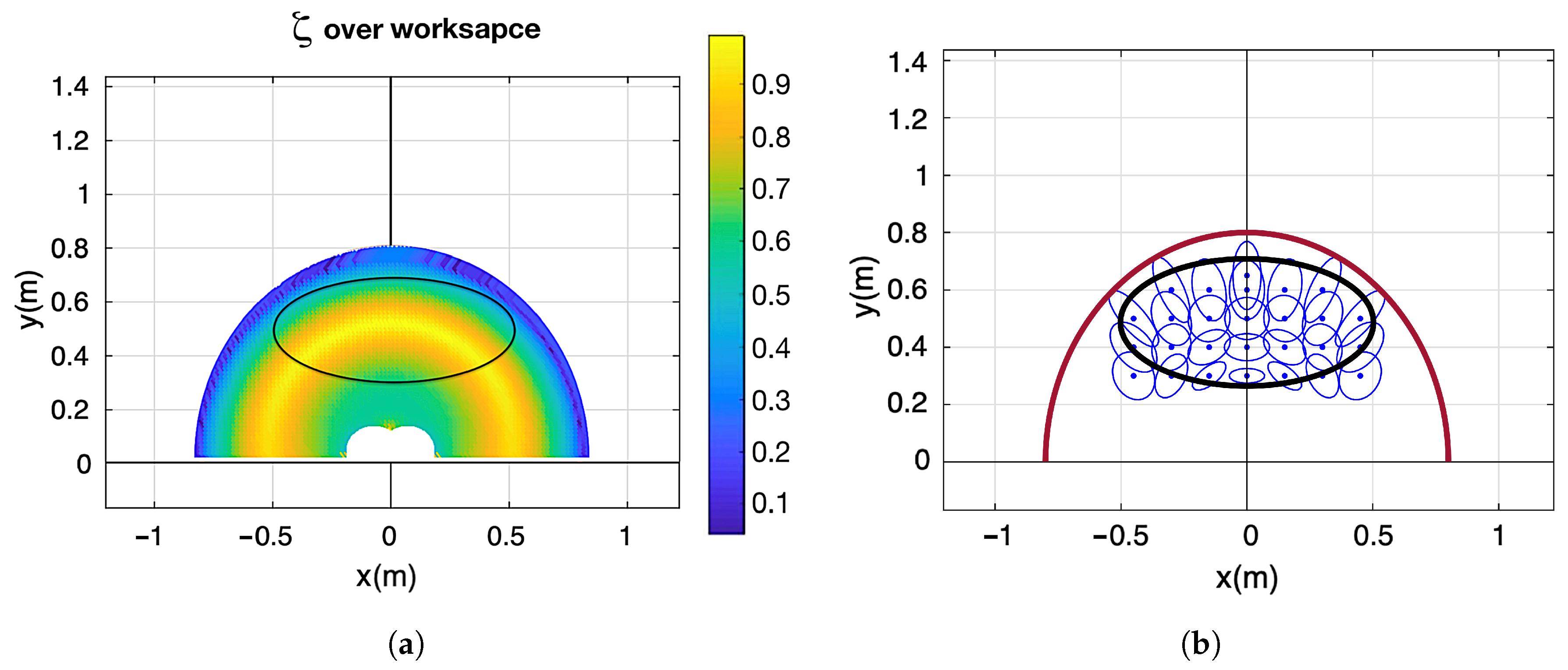
After applying the optimized link lengths, the conditioning index and the manipulability force ellipses were plotted on the workspace and the results are shown in Figure 8.
The conditioning index is larger than 0.6 on the whole workspace and higher than 0.75 on 90% of the workspace. Better manipulability is therefore achieved if compared to the 3DOM architecture [24], which provides a conditioning index larger than 0.2 on the whole workspace, higher than 0.33 on 97% of the workspace and higher than 0.5 on 84% of the workspace. The manipulability force ellipses also reflect an acceptable manipulability index due to their not extremely elongated shape. Moreover, the ellipses plots highlight the symmetric distribution of manipulability, demonstrating an identical kinetostatic performance for right-handed and left-handed users.
3.3. Kinetostatics
The selection of the desired specifications for the actuators was based on the maximum torque and maximum velocity required on the actuated joints.
- Maximum torque:The robot target is 28 N, as the one of the MIT-MANUS [27], taken as a reference value for its considerable clinical exploitation. This force is translated to joints and on the basis of Equations (26)–(28).where T is the torque matrix, and are the torques transferred to and , respectively, J is the Jacobian, F is the force matrix and and are the forces exerted by the patient in the x-direction and y-direction, respectively. Based on Equations (26)–(28), the maximum torque translated to the actuated joints is calculated to be equal to 11.2 Nm.
- Maximum velocity:Considering common neurorehabilitation exercises, the maximum velocity required at the end-effector is assumed to be lower than 0.5 m/s in the Cartesian space. In fact, Krebs et al. states, with experiments, that the tangential velocities for circular movements performed by stroke patients is below 0.5 m/s [28]. They also present linear velocities for point-to-point movements lower than 0.25 m/s. The corresponding angular velocity on the joints depends on the configuration of the manipulator and it is maximal when the minimum singular value of the Jacobian is minimal. Accordingly, the maximum angular velocity needed on the actuated joints was calculated to be equal to 4 rad/s or 38 RPM.
4. Prototype
4.1. Description
On the basis of the considerations reported in the previous sections, the PLANarm2 prototype was developed and assembled. The mechanical assembly of the manipulator is composed of five subsystems: base, motors, transmission, links and end-effector. A proper mechatronic design has to consider that the choice of all the components must be carried out keeping in mind the expected behaviour of the final controlled device.
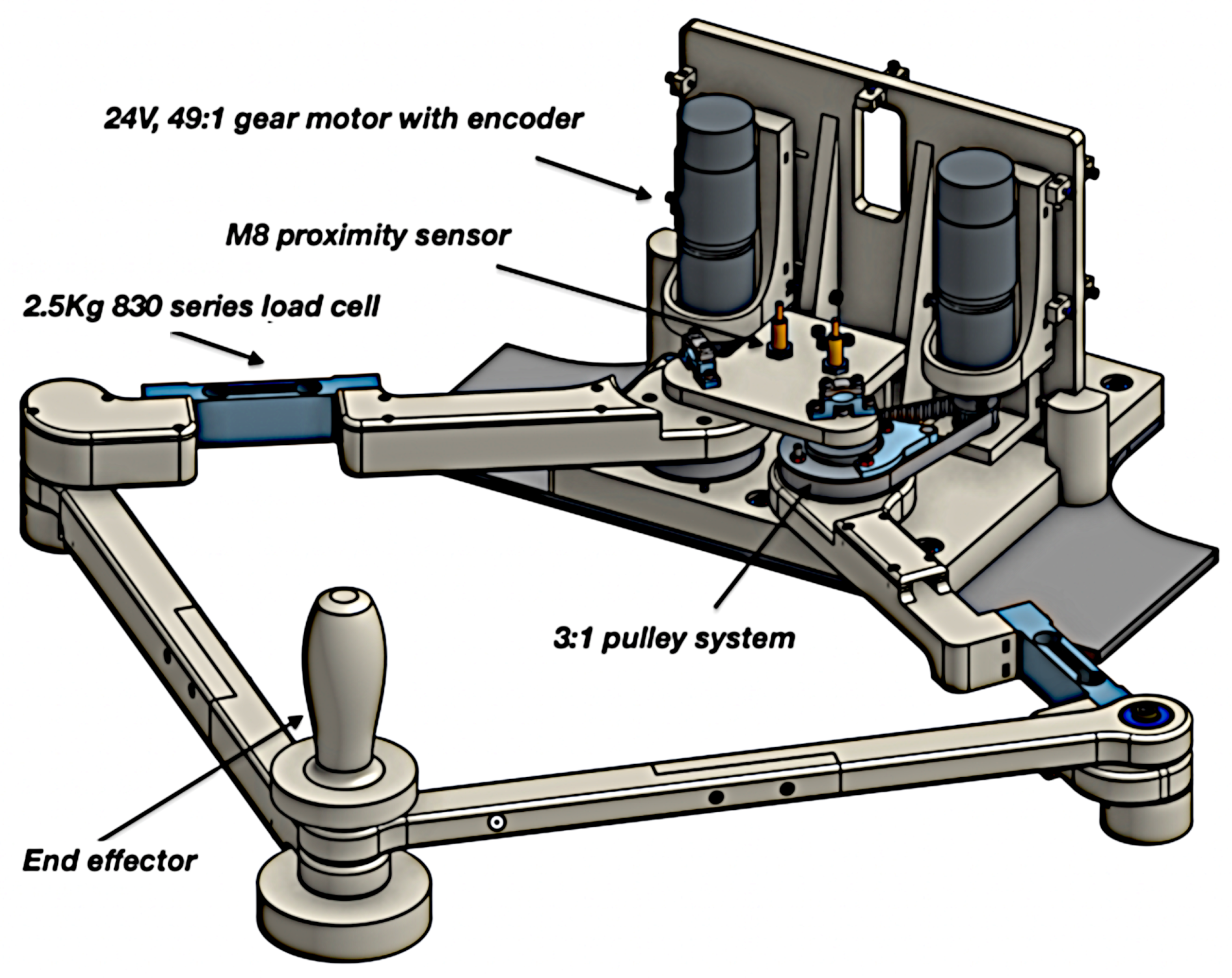
Impedance and its dual admittance control are today part of the state-of-the-art in physical Human–Robot Interaction (pHRI) and essential control strategies for rehabilitation devices. Impedance control requires a direct force/torque control [29] and backdrivable motors are therefore preferred. High torque and low velocity needed for this application, as reported in Section 3.3, clash with the characteristics of electrical motors that in general express high velocity and low torque. High torque and low velocity electrical motors (i.e., torque motors) are available on the market, but they are generally expensive, and not suitable for the low-cost device described. PLANarm2 is moved by two 24 V motors (EMG49 model from Robot-electronics) equipped with a non-backdrivable 49:1 gearbox (resulting in a no-load speed of 143 rpm and a stall torque of 19.6 Nm) further reduced by a 3:1 pulley belt transmission connected to the corresponding link.
The links have been designed to embed a Cantilever Beam load cell (Model 830, Richmond Industries Ltd., Reading, UK) measuring the torque transmitted through the links actuated by motors. This solution allows to evaluate straightforwardly the torque by measuring the shear force at the cantilever sensor and multiplying it by the length of the link. This motor choice reflects in the impossibility to use an impedance control algorithm in favour of an admittance strategy, which requires force sensing and good position/velocity control. Each actuator is equipped with an incremental encoder sensor with a final resolution on the link rotation of 0.00213 rad. The low-level controller, in line with the affordability nature of the device, is represented by an Arduino DUE board (Atmel SAM3X8E based on a ARM Cortex-M3) that, in conjunction with two VNH5019 motor drivers, provides full control of the robot’s movements. The Arduino board, the motor drivers and other electronic elements required to operate, are installed on a PCB and mounted on the device. Closed control loops are processed directly by the Arduino board and not by additional commercial motor drivers. This choice has been made in order to exploit the low cost and versatility of a general purpose microcontroller unit (MCU).The MCU controller communicates with a PC through a serial RS-232. PC will be responsible for the high-level control logic and GUI for robot control.
Proximity sensors are used to detect the end stroke of each arm, as a reference for the incremental encoders. The large majority of the components have been 3D-printed. The complete mechanical structure is shown in Figure 9.
4.2. Cost Estimation
The device is designed specifically for being an affordable rehabilitative device with a low-volume production. Given the complexity of some parts of the device and its intrinsic prototype nature, the most flexible and suitable technology for this production volume is Additive Manufacturing (AM) thanks to the ability to run a production without the long term investment in specific tooling and the flexibility on implementing any layout adjustment, upgrade or customization.
The device has been optimized to be produced out of polymeric materials on a Fused Deposition Modelling (FDM) AM machine. The specific machine used to print the device is a Stratasys F370 printer and the used materials are Stratasys ABS and Stratasys QSR soluble support material both in the mm filament diameter. The print project consists of 4 different print trays for a total of 97 printing hours, 2292 cm3 of building material and 446 cm3 of support material, with additional 25 h of washing time (most of them performed while the machine was printing other subsequent trays). The magnitude of the building cost could be roughly estimated with the cost of building material (Stratasys ABS cost: EUR/cm3 (in 2020)) added to the cost of support material (Stratasys QSR cost: EUR/cm3 (in 2020)) used along the fabrication and is approx € 501. The concept of affordability has been employed for the selection of essential components like electric motors and drivers, load cells and electronics components too, bringing the cost of bought material to a rough total of € 720. For the assembly of the structure, one single operator was able to perform the whole operation during a single working day time with no specific tools and with a few other components like standard metric screws, nuts, ball bearings and pulleys, for an additional rough cost of € 100. Two additional days were required to assemble the electrical and electronic assembly and wiring, for a rough cost of € 200. Regarding the aforementioned observations, with a total estimated cost of € 1521, PLANarm2 could be considered an affordable device for a limited production run.
5. Control
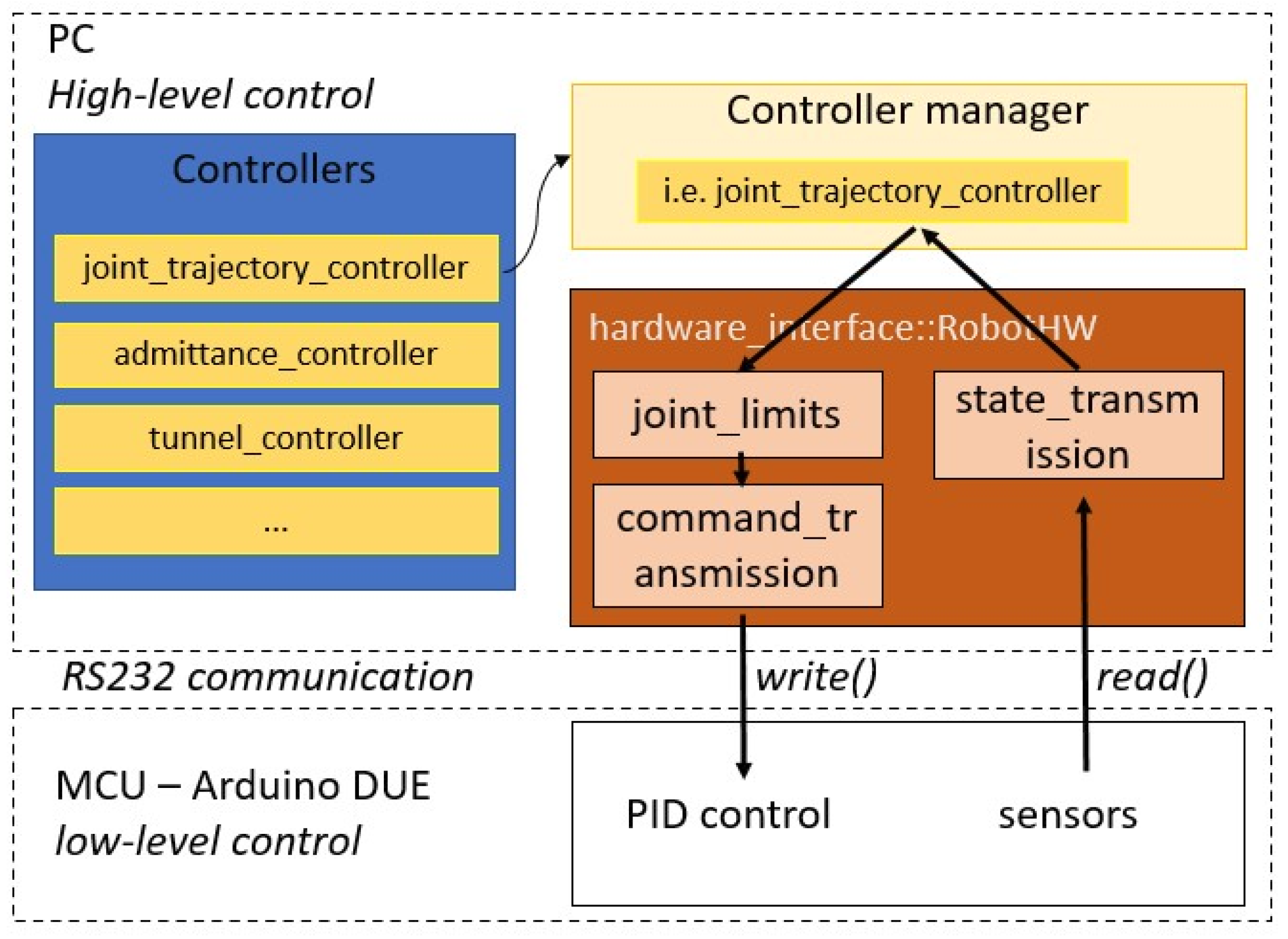
When designing a rehabilitation device, mechatronic and control aspects are equally important. Following [30], it is possible to divide the existing control strategies for neurorehabilitation devices into three main branches: assistive, intended to help patients perform certain movements; corrective, intended to help patients improve their movement accuracy; and resistive, intended to further challenge the patient’s capabilities. The authors decided to make available all these control strategies for the user of the PLANarm2 device. In particular, the assistive mode is realized both by a passive trajectory_controller and by an active admittance_controller, the corrective mode is introduced through a so-called tunnel_controller and the resistive mode is implemented as a particular case of the admittance control. In order to develop an effective and modular control architecture, the authors decided to leverage the functionalities of the ros_control package [31], available within the Robotic Operative System (ROS) framework [32]. With reference to Figure 10, the control structure is made up of four main components: a controller manager, the set of available controllers, a hardware interface and the real controlled robot. The controller manager is responsible for handling the controllers implemented in the system; it activates, deactivates and switches them depending on the user’s command. Once a specific controller is activated, it has access to the current state of the robot and, depending on its internal algorithm, it can use that information to compute the next command to be sent to the robot. This back and forth data transmission is made possible by the hardware interface component of the control architecture, in charge of interfacing the software portion of the system with the hardware one through the read() and write() methods. For this specific application, the hardware_interface has also been equipped with a dummy transmission performing the transformation between Cartesian space and actuator space so that commands can be computed more intuitively referring to the Cartesian reference frame.
As from Figure 10, the control structure could be split in low-level control and high-level control. The low-level portion of the control architecture is represented by the PID loops for position and velocity control running on the Arduino DUE board. These capabilities are often built-in for commercial robotic devices but, in this case, given the use of a general purpose Arduino DUE for cost-effectiveness and flexibility reasons, they must be redesigned from scratch. The high-level portion is implemented on a PC to exploit the ros_control capabilities.
5.1. Low-Level Control
A fundamental requirement for the implementation of the PID loops is to guarantee a fixed control time step. This has been achieved by equipping the micro-controller with ChibiOS [33], an efficient open-source Real Time Operative System (RTOS) specifically designed for embedded applications. Using ChibiOS, it is possible to guarantee a time step of 1 ms for measure and control, while ensuring a 200 Hz communication with PC via serial interface.
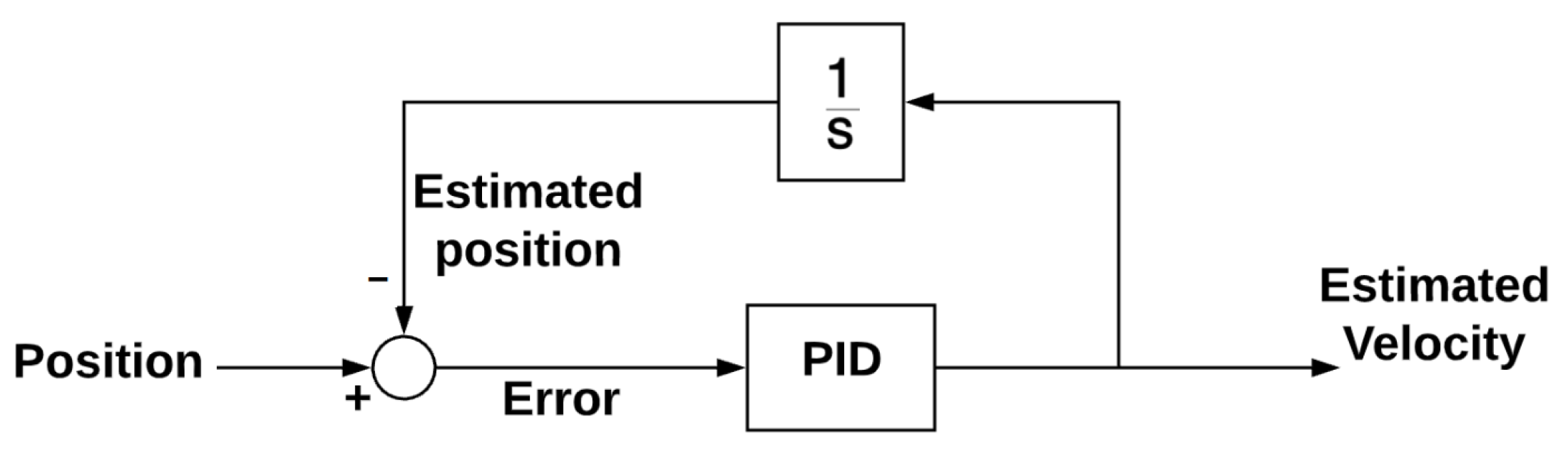
As highlighted in Section 4, the chosen actuators are sold with an embedded incremental encoder for precise position measurement. However, no velocity sensor was installed on the motors and therefore the speed value had to be estimated using the PID loop depicted in Figure 11.
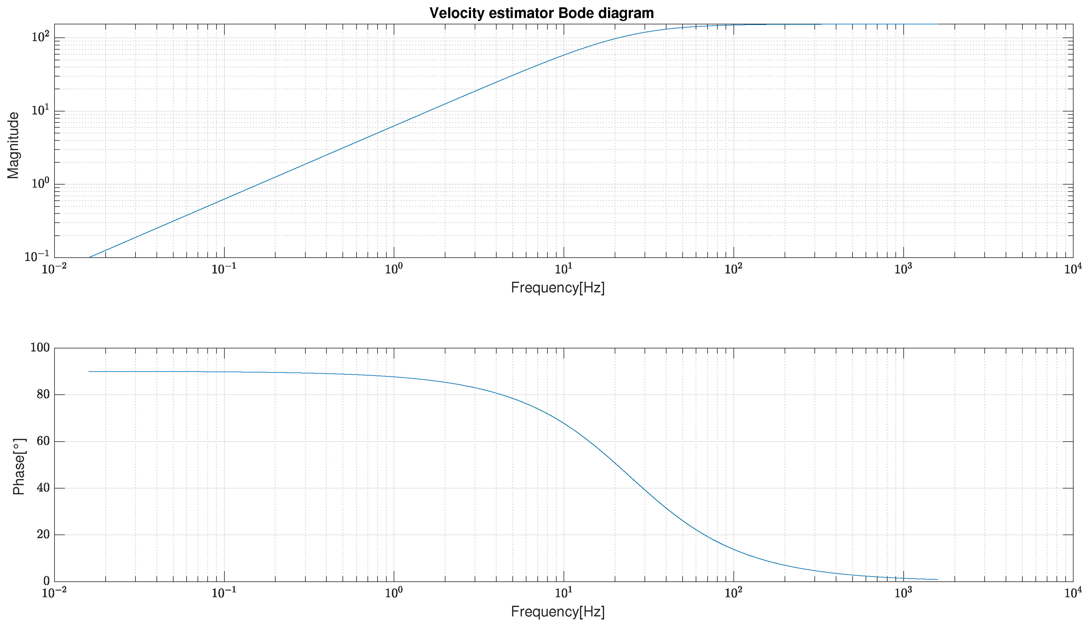
The performance of the velocity estimator was then analysed in terms of frequency response and the corresponding Bode diagram is reported in Figure 12.
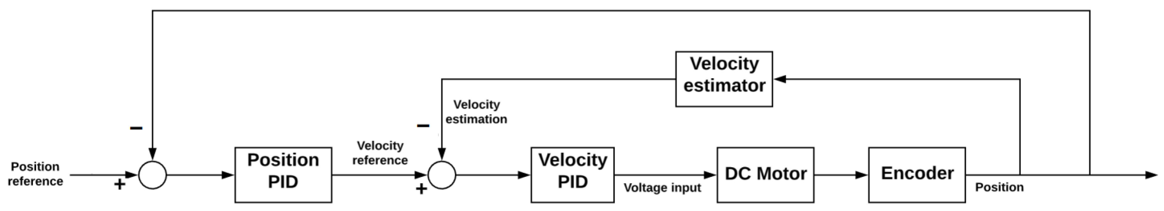
The velocity_controller was then realized using a common PID loop and the speed estimator just introduced. Similarly, the position_controller was implemented by encapsulating the velocity_controller within an additional PID loop, as schematized in Figure 13.
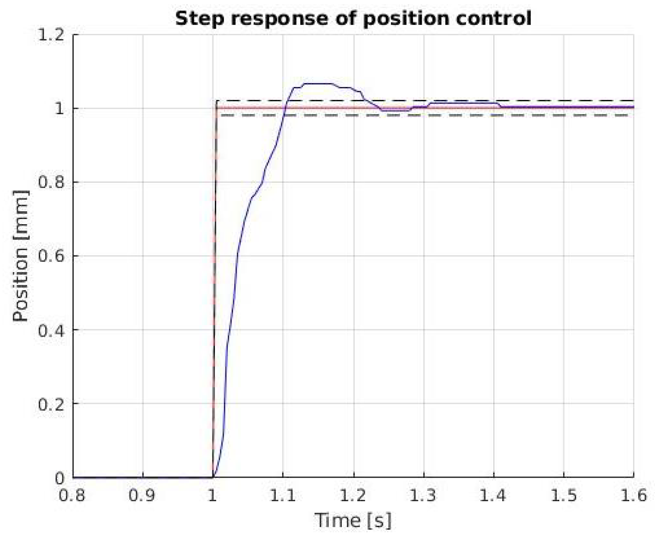
With reference to Figure 14, the response of the position_controller to a step input is characterized by a 5% overshoot, a settling time of 0.21 s and a steady state error lower than 0.5%, which is considered acceptable for the application of interest.
5.2. High-Level Control
Now, on top of the basic robot functionalities just presented, it is possible to implement the rehabilitation-specific controllers introduced at the beginning of this section.
5.2.1. Trajectory Controller
The trajectory_controller can be used to perform passive rehabilitation exercises. Since it is a common tool, the authors decided to exploit the so-called joint_trajectory_controller [34], available as part of the ros_control package. This controller takes as input trajectories specified as a set of waypoints to be reached at specific time instants and attempts to execute them as well as the mechanism allows. The interpolation between waypoints can be performed using linear, cubic or quintic 1D splines, depending on the level of continuity that has to be guaranteed. For this specific project, the authors chose to specify a desired position, velocity and acceleration for each waypoint and then used quintic splines interpolation to ensure continuity at the acceleration level. Thanks to the trajectory controller, PLANarm2 is capable of following any path that lays within the workspace of the robot with the performances achieved by the position controller, described in Section 5.1.
5.2.2. Admittance Controller
Starting from Hogan’s work [29], indirect force control strategies such as impedance and its dual admittance control can be considered the most proper and efficient way to control a robot interacting with its environment. As highlighted in [30], impedance and admittance control are also the simplest and probably most used way to carry out an assistance-as-needed control in robotic neurorehabilitation. The possibility to change on-line their parameters, and therefore the robot’s behaviour, also allows to sophisticate the algorithm in several ways. As reported in Section 4, in order to guarantee the device’s simplicity and affordability, it is not possible to realize a direct effort control. This seems to clash with the need to realize a haptic device and, for this reason, the authors choose a strategy similar to the one described in [35]. Given a reference force , coming from the digital environment connected to the device, it is possible to control the motors with a velocity reference () obtained through a PI control loop over the force error , where with being the measured force. For the sake of simplicity, Equation (29) has been written only for one of the controlled joints:
The proportional parameter in Equation (29) is called to highlight that the transparency felt by the user will increase while , that can be associated to a virtual damping, decreases. A proper choice of these parameters must also take into account the disturbance rejection.
5.2.3. Tunnel Controller
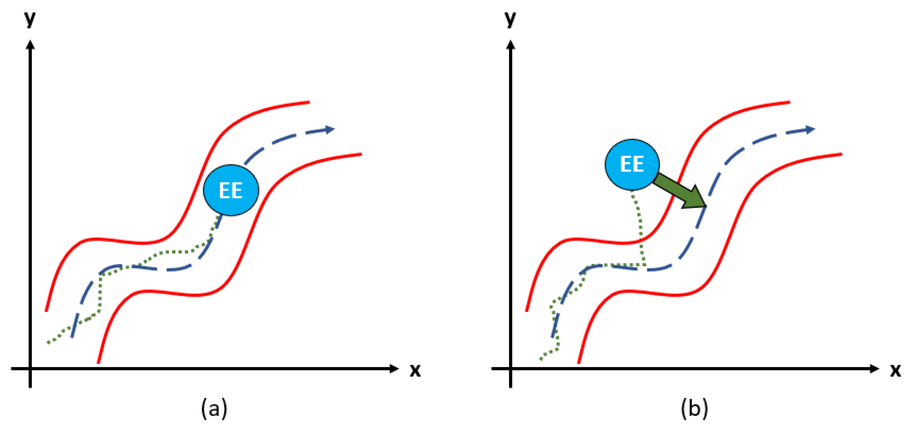
Corrective rehabilitation is proven effective when aiming to improve motion coordination. To provide this functionality, the authors decided to develop a so-called tunnel_controller, similar to what is presented in [36]. The controller takes as input a predefined trajectory and builds a virtual tunnel of user-defined width around it. The patient is allowed to move freely along the path and, whenever the tunnel’s boundaries are exceeded, a restoring force is produced in order to correct the undesired movement. A schematic representation of this concept is reported in Figure 15.
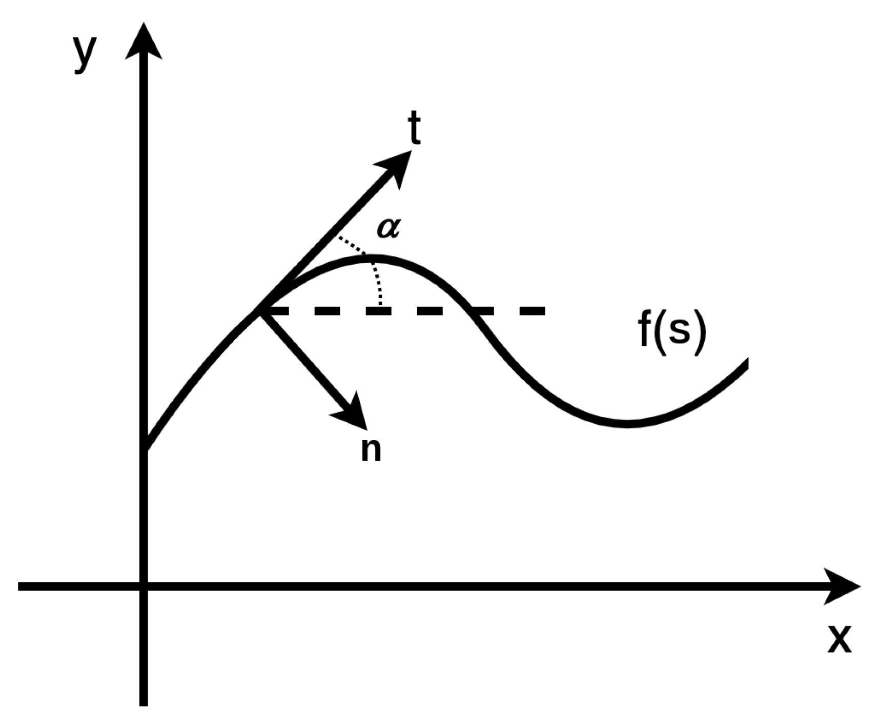
Differently from the trajectory_controller, for which input trajectories are time-parametrized, the tunnel_controller requires paths expressed in terms of curvilinear abscissa s. In order to guarantee coherence with the other controllers, a method that automatically transforms a time-parametrized trajectory into its corresponding s-version has been implemented so that the same computed trajectory can be applied to all the available controllers. In addition, a new coordinate system has been defined on the trajectory at any instant, denoting by and the tangential and the normal vectors, respectively, where = , as shown in Figure 16.
The patient’s force on the end-effector is projected from the Cartesian reference frame to the new reference frame according to the instantaneous slope of the requested trajectory. Then, the controller’s basic working principle is similar to the one of the admittance_controller. For every control cycle, the normal distance between desired and actual position of the end-effector, with respect to the given trajectory, is calculated. If that distance is smaller than the user-defined tunnel half-width W, tangential and normal measured forces are given as input to a high-level PI loop set with a reference of 0N. On the contrary, if the end-effector is detected outside said tunnel, the force used as reference for the PI loop related to the normal direction is computed as in Equation (30), where represents the stiffness of the virtual spring responsible for the generation of the corrective force.
The effect of this approach is that the patient is allowed to move freely inside the virtual tunnel but, whenever the boundaries are exceeded, a virtual spring generates a corrective force that compensates the error and guides the end-effector back inside the tunnel. On top of this, an acceleration limit has been implemented within the controller’s logic for safety reasons: if any spasm or sudden movement of the patient occurs, it can be absorbed.
6. Experimental Assessment
This section presents the results of the experimental assessments performed on the developed prototype. The objective of these experimental tasks is to carry out functional tests able to confirm the goodness of the mechatronic project and control structure chosen. Improvements on the algorithms presented in this work are already under consideration by the authors. Notice that the performance of the trajectory_controller is directly connected to the results obtained for the low-level position_controller reported in Section 5.1 and therefore not reported here for brevity. However, data collected for the admittance_controller and the tunnel_controller together with an analysis on the accuracy of the position measurements are discussed in detail hereafter.
6.1. Admittance Controller Validation
The admittance controller was tested on the PLANarm2 prototype. The algorithm has been implemented starting from Equation (29). The final implemented algorithm is slightly different from the ideal case since, for instance, the noise affecting the measured force must be considered. For this reason, the signal coming from the sensors is processed with a simple exponential filter. This filter can be expressed by the formula:
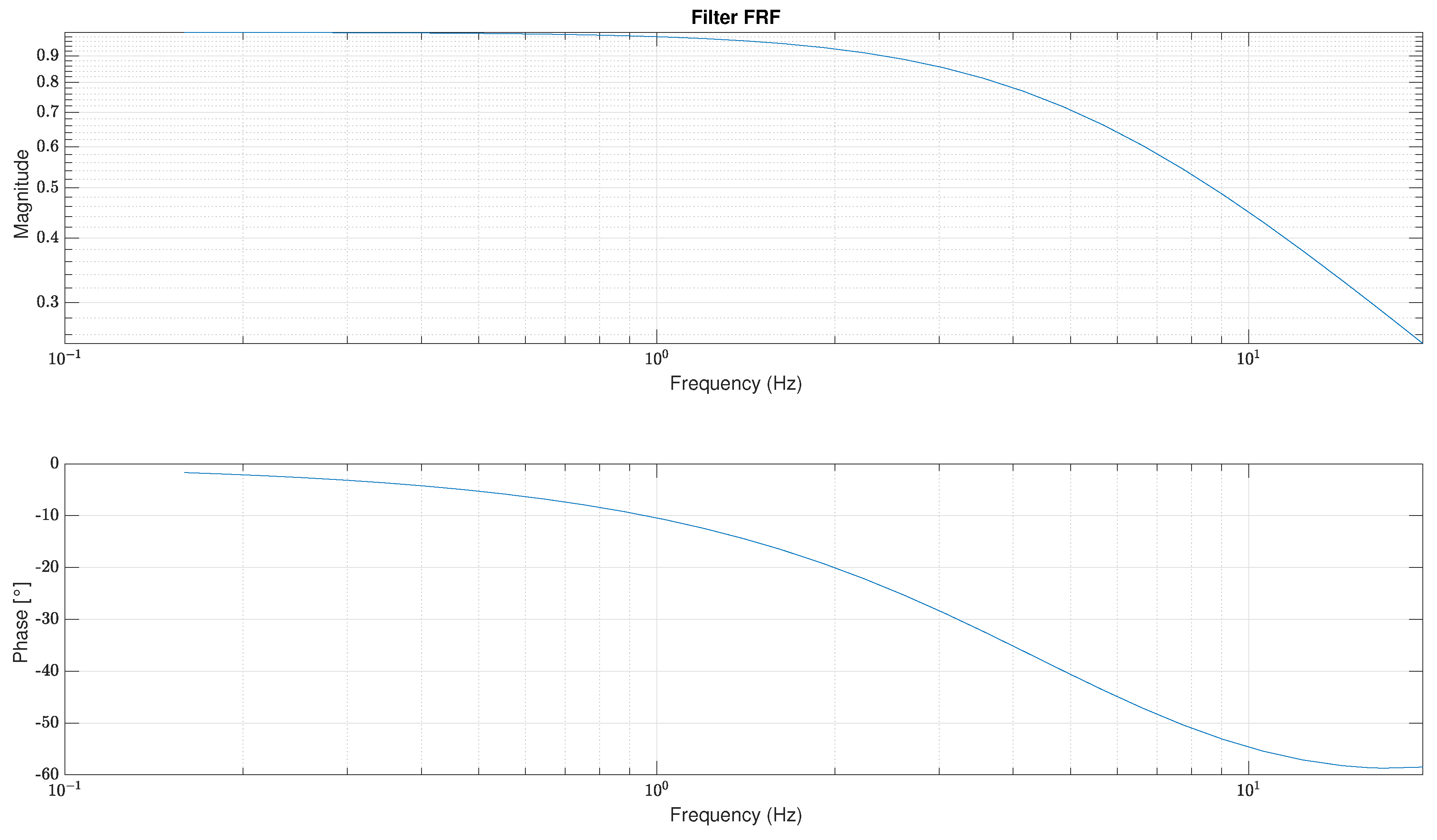
In this case, is taken as with the ideal cut off frequency. This filter was chosen because of its simplicity and functionality. Its frequency response is represented in Figure 17, showing a magnitude >70% before the cutoff frequency.
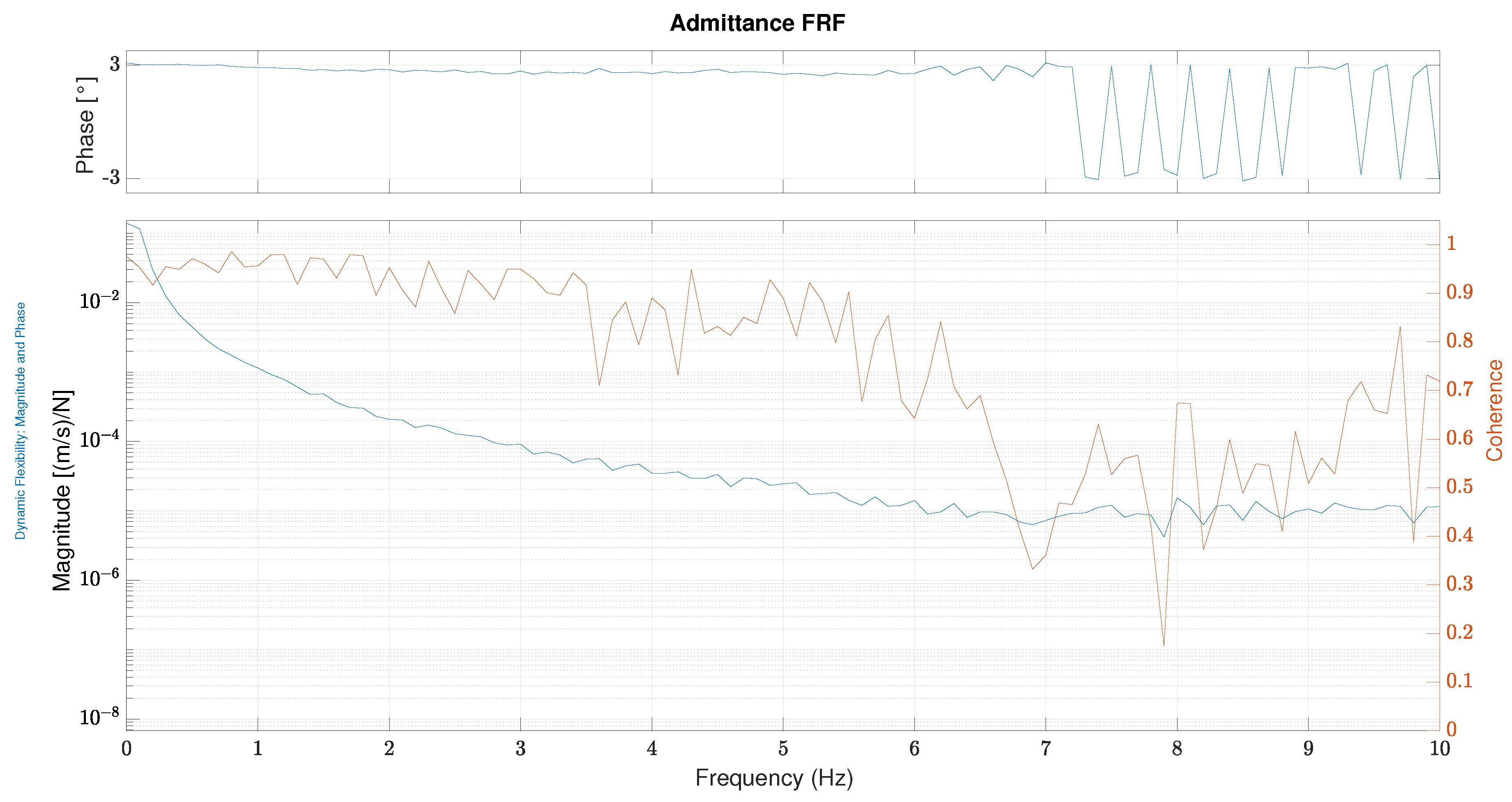
Different kinds of filters (n-order filters) are under consideration of the authors in order to improve the performances in terms of admittance readiness. Starting from the filtered force measures, the PI control loop (following Equation (29)) is implemented on the high-level control hardware, running at 200 Hz. The admittance_controller’s performance is presented in terms of frequency response function between measured force () and measured velocity on a single axis (y axis considering the reference presented in Figure 3) in a particular configuration (x = 0, y = 0.5). Similar results could be obtained for the perpendicular axis.
In Figure 18, the frequency response function (FRF) for the admittance/force-tracking control is depicted. The graph shows a coherence >80% until 5 Hz of frequency, meaning that the output measured can be considered related to the input. Phase is quite constant until 7 Hz and shows a small delay for the frequency range between 0 and 7 Hz. The magnitude trend begins with a fall due to the pole in the origin and the stabilizes around 7 Hz.
6.2. Tunnel Controller Validation
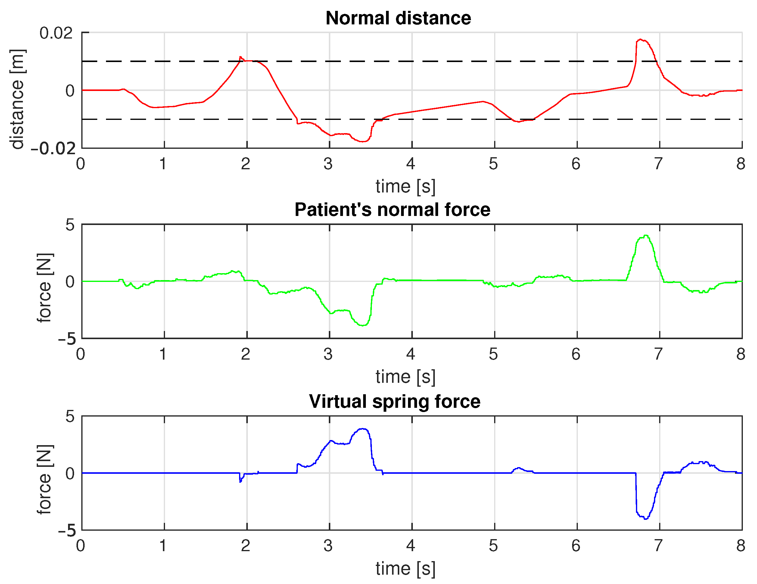
As explained in Section 5.2, as long as the end-effector remains within the tunnel’s boundaries, the tunnel_controller is based on the same working principle of the admittance_controller. For this reason, the assessment of the behaviour of PLANarm2 in those conditions is redundant and is not discussed here. On the other hand, it is interesting to see what happens whenever the end-effector is guided against the mentioned boundaries. The controller was set up with the following parameters: and for the force tracking loop, N/m and m for the virtual stiffness and the half-width of the tunnel, respectively. Figure 19 reports the data collected while moving the end-effector along a certain predefined trajectory. The top plot represents the normal distance from the given trajectory against time together with an indication of the tunnel’s boundaries (black dashed line). It can be easily noticed that during the experimental run the end-effector was driven outside of those boundaries a few times. The plot in the middle depicts the trend of the force exerted on the end-effector in the direction normal to the desired trajectory, while the bottom plot reports the trend of the corrective force produced by the virtual spring. As shown, the end-effector is free to move within the tunnel boundaries with the same performances highlighted for the admittance_controller. However, as soon as the end-effector is driven against the tunnel boundaries, the force required to further increase the normal distance from the trajectory rises due to the corrective force generated by the virtual spring. It is worth mentioning that, as can be seen in Figure 19, a certain degree of discontinuity in the force produced by the virtual environment has been maintained. This choice is justified by the fact that thanks to the discontinuity itself, the patient can intuitively "feel" the contact with the tunnel’s boundaries and try to autonomously correct its motion.
6.3. Position Measurement Accuracy
Each actuated joint is driven, through a proper transmission system, by a motor with an embedded incremental encoder. The measured position is then transformed to the joint space by multiplying by the gear ratio of the transmission system (3:1). Finally, the position in the joint space reference is converted to the Cartesian space reference. This procedure of obtaining the position in the Cartesian reference, along with the inaccuracies generated in the embedded encoder, contribute to the generation of a measurement error. In order to quantify this measurement error, a test to measure the accuracy of the device was performed.
6.3.1. Test Bench
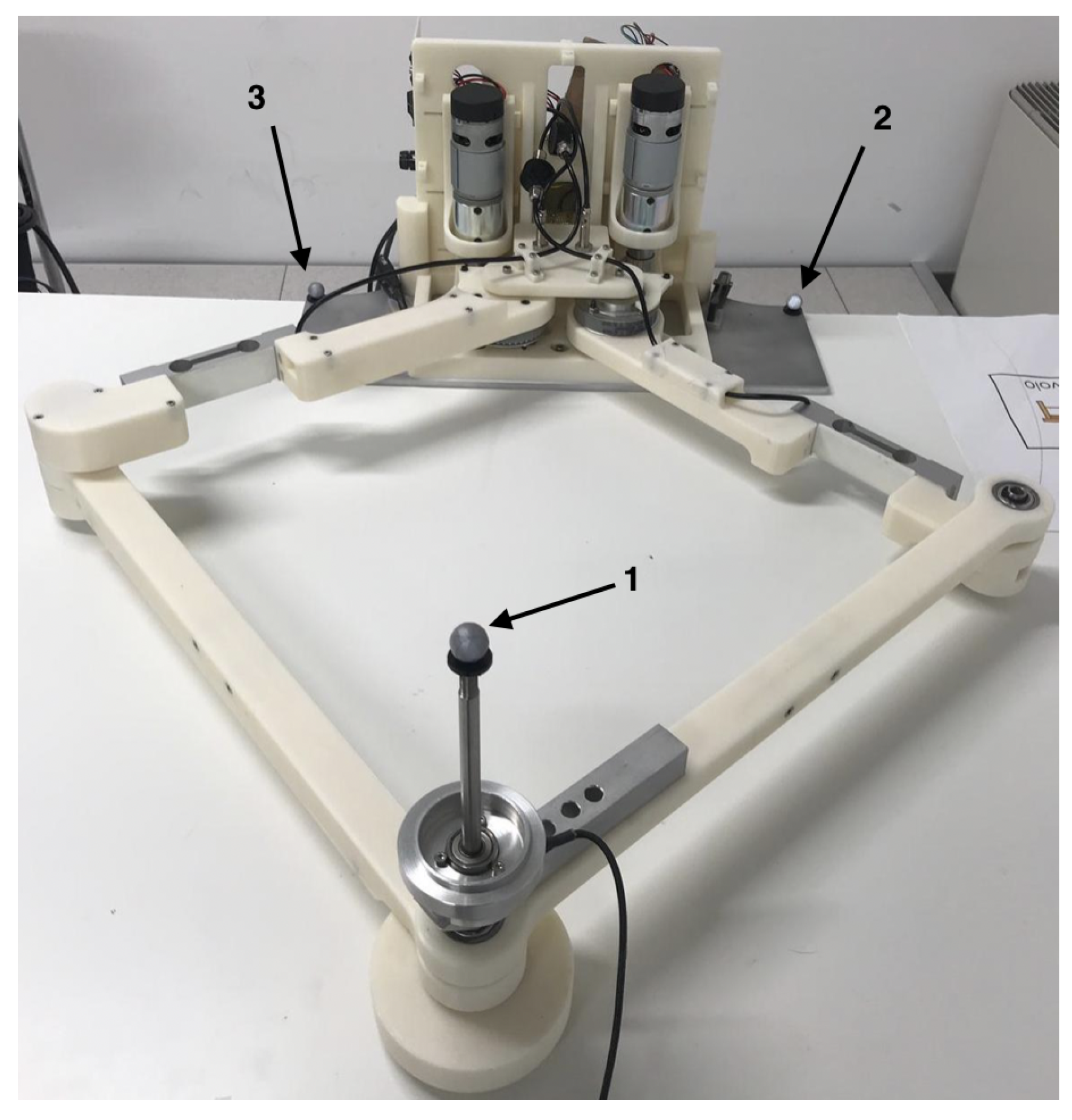
In order to measure the actual position of the end-effector, a Vicon marker-based motion capture system was used. The system was setup with 10 cameras tracking the motion of reflective trackers installed on the device. A table was placed within the area under the scope of the cameras and the PLANarm2 device was installed on it. Then, three markers were installed on the planar manipulator as shown in Figure 20: two were placed on the base to act as reference frames, and one was installed on the end-effector to track its position.
6.3.2. Data Analysis
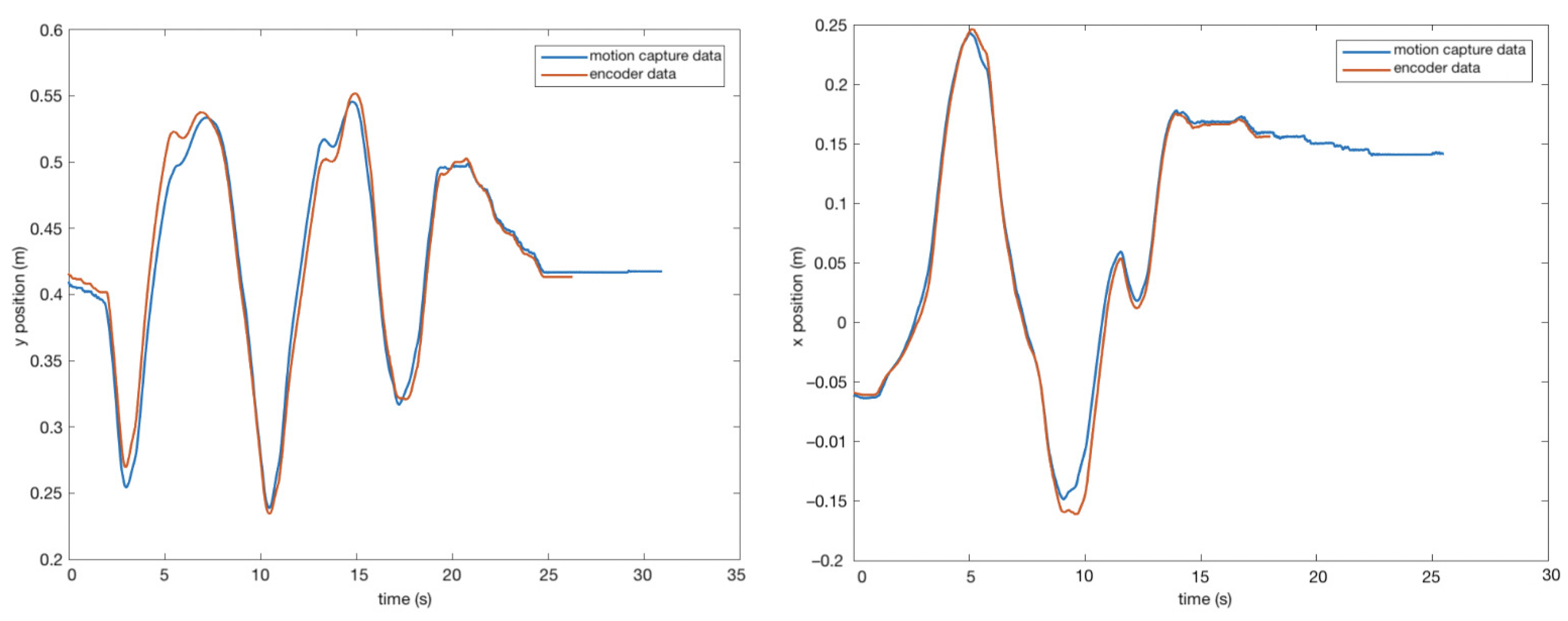
After recording the position of the end-effector using the Vicon Nexus software, the results were plotted against the measurements taken by the encoder, along a generic, irregularly-shaped trajectory.
As it can be seen from Figure 21, there exists a small error when comparing the position taken from the motion capture cameras and the position recorded from encoder. This error arises from the combination of different factors, including encoder uncertainties as well as mechanical measurements inaccuracies related to the lengths of the links. Moreover, mechanical backlash is another source of error, as can be noticed in the inversion of the motion. However, the maximum error recorded when comparing the two results was 0.02 m and the average was 0.009 m, considered acceptable for the final application.
7. Conclusions
As a result of the increasing number of patients suffering disabilities due to stroke, many research groups have proposed devices aimed at facilitating the rehabilitation process. However, most of these devices are technically advanced and designed for clinical use. This paper presents the prototype of an affordable device for upper-limb neurorehabilitation based on a planar five-bar parallel kinematic mechanism.
The optimal link lengths were obtained by optimizing the conditioning index and the minimum singular value of the Jacobian over the workspace. Components were chosen starting from kinematic and dynamic evaluations as well as on the desired performances. A 3D-printed prototype was presented and the main components and characteristic were analysed. Different kinds of controllers were implemented in order to verify the effectiveness of the prototype and the goodness of the design. Both active and passive controllers were tested and the measured performances showed a good dynamic behaviour. In order to validate the measurements of the end-effector position, a test procedure was followed. The position of the end-effector was recorded using motion capture cameras and compared to the measurements obtained from the encoders. It was shown that the measurements taken by the encoders are accurate enough for the target application.
Next steps will include more refined admittance and assist-as-needed control algorithms, starting from the obtained results and considering new improvements, in order to assist the patients in performing the required tasks according to their capabilities. Finally, a graphic user interface is being implemented in order provide a visual feedback to the patient while performing rehabilitation tasks.
Author Contributions
Conceptualization, J.Y. and M.M.; data curation, J.Y., A.P. and M.L.N.; formal analysis, J.Y.; funding acquisition, M.M.; investigation, J.Y., A.P. and M.L.N.; methodology, J.Y.; resources, T.D. and M.M.; software, J.Y., A.P. and M.L.N.; supervision, H.G. and M.M.; validation, J.Y., A.P. and M.L.N.; visualization, J.Y., A.P. and M.L.N.; writing—original draft, J.Y.; writing—review and editing, J.Y., A.P., M.L.N. and M.M. All authors have read and agreed to the published version of the manuscript.
Funding
This work was partially funded by Fondazione Cariplo within the EMPATIA@Lecco project, Rif. 2016-1428 Decreto Regione Lombardia 6363 del 30/05/2017.
Acknowledgments
The authors would like to thank: João Carlos Dalberto and Roberto Bozzi for supporting the mechanical and electrical realization of the prototype; Alessandra Tafaro and Roberta Pozzi for the administrative support of the project.
Conflicts of Interest
The authors declare no conflict of interest. The funders had no role in the design of the study; in the collection, analyses, or interpretation of data; in the writing of the manuscript, or in the decision to publish the results.
References
- Millán, M.; Dávalos, A. The Need for New Therapies for Acute Ischaemic Stroke. Cerebrovasc. Dis. 2006, 22 (Suppl. S1), 3–9. [Google Scholar] [CrossRef]
- Maciejasz, P.; Eschweiler, J.; Gerlach-Hahn, K.; Jansen-Troy, A.; Leonhardt, S. A survey on robotic devices for upper limb rehabilitation. J. Neuroeng. Rehabil. 2014, 11, 3. [Google Scholar] [CrossRef] [PubMed] [Green Version]
- Zhang, X.; Yue, Z.; Wang, J. Robotics in Lower-Limb Rehabilitation after Stroke. Behav. Neurol. 2017, 2017, 1–13. [Google Scholar] [CrossRef] [PubMed] [Green Version]
- Krebs, H.; Hogan, N.; Volpe, B.; Aisen, M.; Edelstein, L.; Diels, C. Overview of clinical trials with MIT-MANUS: A robot-aided neuro-rehabilitation facility. Technol. Health Care 1999, 7, 419–423. [Google Scholar] [CrossRef] [PubMed]
- Marchal-Crespo, L.; Reinkensmeyer, D.J. Review of control strategies for robotic movement training after neurologic injury. J. Neuroeng. Rehabil. 2009, 6, 20. [Google Scholar] [CrossRef] [PubMed] [Green Version]
- Toth, A.; Fazekas, G.; Arz, G.; Jurak, M.; Horvath, M. Passive robotic movement therapy of the spastic hemiparetic arm with REHAROB: report of the first clinical test and the follow-up system improvement. In Proceedings of the 9th International Conference on Rehabilitation Robotics (ICORR), Chicago, IL, USA, 28 June–1 July 2005; pp. 127–130. [Google Scholar] [CrossRef]
- Malosio, M.; Pedrocchi, N.; Tosatti, L.M. Robot-assisted upper-limb rehabilitation platform. In Proceedings of the 2010 5th ACM/IEEE International Conference on Human-Robot Interaction (HRI), Osaka, Japan, 2–5 March 2010; pp. 115–116. [Google Scholar] [CrossRef]
- Li, G.; Cai, S.; Xie, L. Cooperative Control of a Dual-arm Rehabilitation Robot for Upper Limb Physiotherapy and Training. In Proceedings of the 2019 IEEE/ASME International Conference on Advanced Intelligent Mechatronics (AIM), Hong Kong, China, 8–12 July 2019; pp. 802–807. [Google Scholar] [CrossRef]
- Prochazka, A. Passive Devices for Upper Limb Training. In Neurorehabilitation Technology; Springer: London, UK, 2012; pp. 159–171. [Google Scholar]
- Rehmat, N.; Zuo, J.; Meng, W.; Liu, Q.; Xie, S.Q.; Liang, H. Upper limb rehabilitation using robotic exoskeleton systems: A systematic review. Int. J. Intell. Robot. Appl. 2018, 2, 283–295. [Google Scholar] [CrossRef]
- Qassim, H.M.; Wan Hasan, W.Z. A Review on Upper Limb Rehabilitation Robots. Appl. Sci. 2020, 10, 6976. [Google Scholar] [CrossRef]
- Gull, M.A.; Bai, S.; Bak, T. A Review on Design of Upper Limb Exoskeletons. Robotics 2020, 9, 16. [Google Scholar] [CrossRef] [Green Version]
- Zuccon, G.; Bottin, M.; Ceccarelli, M.; Rosati, G. Design and Performance of an Elbow Assisting Mechanism. Machines 2020, 8, 68. [Google Scholar] [CrossRef]
- Cafolla, D.; Russo, M.; Carbone, G. CUBE, a Cable-driven Device for Limb Rehabilitation. J. Bionic Eng. 2019, 16, 492–502. [Google Scholar] [CrossRef]
- Avizzano, C.A.; Satler, M.; Cappiello, G.; Scoglio, A.; Ruffaldi, E.; Bergamasco, M. MOTORE: A mobile haptic interface for neuro-rehabilitation. In Proceedings of the 2011 RO-MAN, Atlanta, GA, USA, 31 July–3 August 2011; pp. 383–388. [Google Scholar] [CrossRef]
- Nam, H.S.; Hong, N.; Cho, M.; Lee, C.; Seo, H.G.; Kim, S. Vision-Assisted Interactive Human-in-the-Loop Distal Upper Limb Rehabilitation Robot and its Clinical Usability Test. Appl. Sci. 2019, 9, 3106. [Google Scholar] [CrossRef] [Green Version]
- Zadravec, M.; Matjačić, Z. Planar arm movement trajectory formation: An optimization based simulation study. Biocybern. Biomed. Eng. 2013, 33, 106–117. [Google Scholar] [CrossRef]
- Casadio, M.; Sanguineti, V.; Morasso, P.G.; Arrichiello, V. Braccio di Ferro: A new haptic workstation for neuromotor rehabilitation. Technol. Health Care 2006, 14, 123–142. [Google Scholar] [CrossRef] [PubMed]
- Chaparro-Rico, B.D.M.; Cafolla, D.; Ceccarelli, M.; Castillo-Castaneda, E. NURSE-2 DoF Device for Arm Motion Guidance: Kinematic, Dynamic, and FEM Analysis. Appl. Sci. 2020, 10, 2139. [Google Scholar] [CrossRef] [Green Version]
- Wu, Q.; Chen, B.; Wu, H. Adaptive Admittance Control of an Upper Extremity Rehabilitation Robot With Neural-Network-Based Disturbance Observer. IEEE Access 2019, 7, 123807–123819. [Google Scholar] [CrossRef]
- Zollo, L.; Accoto, D.; Torchiani, F.; Formica, D.; Guglielmelli, E. Design of a planar robotic machine for neuro-rehabilitation. In Proceedings of the IEEE International Conference on Robotics and Automation, ICRA 2008, Pasadena, CA, USA, 19–23 May 2008; pp. 2031–2036. [Google Scholar] [CrossRef] [Green Version]
- Campolo, D.; Tommasino, P.; Gamage, K.; Klein, J.; Hughes, C.M.; Masia, L. H-Man: A planar, H-shape cabled differential robotic manipulandum for experiments on human motor control. J. Neurosci. Methods 2014, 235, 285–297. [Google Scholar] [CrossRef]
- Giberti, H.; Cinquemani, S.; Ambrosetti, S. 5R 2dof parallel kinematic manipulator—A multidisciplinary test case in mechatronics. Mechatronics 2013, 23, 949–959. [Google Scholar] [CrossRef]
- Klein, J.; Roach, N.; Burdet, E. 3DOM: A 3 Degree of Freedom Manipulandum to Investigate Redundant Motor Control. IEEE Trans. Haptics 2014, 7, 229–239. [Google Scholar] [CrossRef]
- Liu, X.J.; Wang, J.; Pritschow, G. Kinematics, singularity and workspace of planar 5R symmetrical parallel mechanisms. Mech. Mach. Theory 2006, 41, 145–169. [Google Scholar] [CrossRef]
- Corona-Acosta, I.P.; Castillo-Castaneda, E. Dimensional Synthesis of a Planar Parallel Manipulator Applied to Upper Limb Rehabilitation. In Multibody Mechatronic Systems; Ceccarelli, M., Hernández Martinez, E.E., Eds.; Springer International Publishing: Cham, Switzerlands, 2015; pp. 443–452. [Google Scholar]
- Krebs, H.I.; Ferraro, M.; Buerger, S.P.; Newbery, M.J.; Makiyama, A.; Sandmann, M.; Lynch, D.; Volpe, B.T.; Hogan, N. Rehabilitation robotics: Pilot trial of a spatial extension for MIT-Manus. J. Neuroeng. Rehabil. 2004, 1, 5. [Google Scholar] [CrossRef] [Green Version]
- Krebs, H.I.; Aisen, M.L.; Volpe, B.T.; Hogan, N. Quantization of continuous arm movements in humans with brain injury. Proc. Natl. Acad. Sci. USA 1999, 96, 4645–4649. [Google Scholar] [CrossRef] [PubMed] [Green Version]
- Hogan, N. Impedance Control: An Approach to Manipulation: Part I—Theory. J. Dyn. Syst. Meas. Control 1985, 107, 1–7. [Google Scholar] [CrossRef]
- Proietti, T.; Crocher, V.; Roby-Brami, A.; Jarrassé, N. Upper-Limb Robotic Exoskeletons for Neurorehabilitation: A Review on Control Strategies. IEEE Rev. Biomed. Eng. 2016, 9, 4–14. [Google Scholar] [CrossRef] [PubMed] [Green Version]
- Chitta, S.; Marder-Eppstein, E.; Meeussen, W.; Pradeep, V.; Tsouroukdissian, A.; Bohren, J.; Coleman, D.; Magyar, B.; Raiola, G.; Lüdtke, M.; et al. Ros_control: A generic and simple control framework for ROS. J. Open Source Softw. 2017, 2, 456. [Google Scholar] [CrossRef]
- Quigley, M. ROS: An open-source Robot Operating System. In Proceedings of the ICRA 2009, Kobe, Japan, 12–17 May 2009. [Google Scholar]
- ChibiOS Free Embedded RTOS. Available online: http://www.chibios.org/ (accessed on 18 November 2020).
- Joint Trajectory Controller. Available online: http://wiki.ros.org/joint_trajectory_controller (accessed on 18 November 2020).
- Seraji, H. Adaptive admittance control: An approach to explicit force control in compliant motion. In Proceedings of the 1994 IEEE International Conference on Robotics and Automation, San Diego, CA, USA, 8–13 May 1994; Volume 4, pp. 2705–2712. [Google Scholar] [CrossRef]
- Ding, B.; Ai, Q.; Liu, Q.; Meng, W. Path Control of a Rehabilitation Robot Using Virtual Tunnel and Adaptive Impedance Controller. In Proceedings of the 2014 Seventh International Symposium on Computational Intelligence and Design, Hangzhou, China, 13–14 December 2014; Volume 1, pp. 158–161. [Google Scholar] [CrossRef]
Figure 1.
3D model of the prototype.

Figure 2.
Four configurations of the planar 5R parallel architecture. (a): “”, (b): “”, (c): “”, (d): “”, by denoting the convex (+) or the concave (−) configuration of the left and the right elbow joints, respectively.
Figure 2.
Four configurations of the planar 5R parallel architecture. (a): “”, (b): “”, (c): “”, (d): “”, by denoting the convex (+) or the concave (−) configuration of the left and the right elbow joints, respectively.

Figure 3.
The planar 5R parallel mechanism.

Figure 4.
Forward kinematics scheme for up-configuration.

Figure 5.
(a) Sketch showing the total reachable workspace by combining the workspace of patients with minimum limb lengths and those with maximum limb lengths. (b) Sketch showing the placement of the rehabilitation device in accordance with the reachable workspace.
Figure 5.
(a) Sketch showing the total reachable workspace by combining the workspace of patients with minimum limb lengths and those with maximum limb lengths. (b) Sketch showing the placement of the rehabilitation device in accordance with the reachable workspace.

Figure 6.
Plot of the minimum singular value over the radial direction for different values of .

Figure 7.
Conditioning index over the radial direction for different values of .

Figure 8.
(a) Plot of conditioning number over the workspace. (b) Plot of the manipulability force ellipses over the workspace.
Figure 8.
(a) Plot of conditioning number over the workspace. (b) Plot of the manipulability force ellipses over the workspace.

Figure 9.
3D model of the prototype.

Figure 10.
Control architecture for PLANarm2.

Figure 11.
Feedback loop of the velocity estimator.

Figure 12.
Bode diagram of the velocity estimator.

Figure 13.
Feedback loop of position controller.

Figure 14.
Step response of position controller.

Figure 15.
Schematic tunnel representation. On the left (a), the end-effector moves freely within the tunnel. On the right (b), a restoring force brings the end-effector back within the tunnel.
Figure 15.
Schematic tunnel representation. On the left (a), the end-effector moves freely within the tunnel. On the right (b), a restoring force brings the end-effector back within the tunnel.

Figure 16.
Reference frame for tunnel control.

Figure 17.
Exponential filter response function with Hz.

Figure 18.
Admittance frequency response function (FRF) with and .

Figure 19.
The top plot shows the normal distance from the desired trajectory against time, the middle plot shows the normal force applied on the end-effector against time and the bottom plot shows the force produced by the virtual spring.
Figure 19.
The top plot shows the normal distance from the desired trajectory against time, the middle plot shows the normal force applied on the end-effector against time and the bottom plot shows the force produced by the virtual spring.

Figure 20.
Placement of the markers on the prototype for the experimental procedure.

Figure 21.
Position of motion capture and encoder vs. time: x-position (right) and y-position (left).
Figure 21.
Position of motion capture and encoder vs. time: x-position (right) and y-position (left).

Publisher’s Note: MDPI stays neutral with regard to jurisdictional claims in published maps and institutional affiliations. |
© 2020 by the authors. Licensee MDPI, Basel, Switzerland. This article is an open access article distributed under the terms and conditions of the Creative Commons Attribution (CC BY) license (http://creativecommons.org/licenses/by/4.0/).
Share and Cite
MDPI and ACS Style
Yamine, J.; Prini, A.; Nicora, M.L.; Dinon, T.; Giberti, H.; Malosio, M. A Planar Parallel Device for Neurorehabilitation. Robotics 2020, 9, 104. https://0-doi-org.brum.beds.ac.uk/10.3390/robotics9040104
AMA Style
Yamine J, Prini A, Nicora ML, Dinon T, Giberti H, Malosio M. A Planar Parallel Device for Neurorehabilitation. Robotics. 2020; 9(4):104. https://0-doi-org.brum.beds.ac.uk/10.3390/robotics9040104
Chicago/Turabian StyleYamine, Jawad, Alessio Prini, Matteo Lavit Nicora, Tito Dinon, Hermes Giberti, and Matteo Malosio. 2020. "A Planar Parallel Device for Neurorehabilitation" Robotics 9, no. 4: 104. https://0-doi-org.brum.beds.ac.uk/10.3390/robotics9040104
Note that from the first issue of 2016, this journal uses article numbers instead of page numbers. See further details here.