Design of Soft Grippers with Modular Actuated Embedded Constraints


1
Department of Engineering, University of Perugia, 05100 Terni, Italy
2
Department of Engineering, University of Perugia, 06125 Perugia, Italy
3
Department of Information Engineering and Mathematics, University of Siena, 53100 Siena, Italy
*
Author to whom correspondence should be addressed.
Robotics 2020, 9(4), 105; https://0-doi-org.brum.beds.ac.uk/10.3390/robotics9040105
Submission received: 31 October 2020
/
Revised: 2 December 2020
/
Accepted: 4 December 2020
/
Published: 6 December 2020
(This article belongs to the Special Issue Kinematics and Robot Design III, KaRD2020)
Abstract
:Underactuated, modular and compliant hands and grippers are interesting solutions in grasping and manipulation tasks due to their robustness, versatility, and adaptability to uncertainties. However, this type of robotic hand does not usually have enough dexterity in grasping. The implementation of some specific features that can be represented as “embedded constraints” allows to reduce uncertainty and to exploit the role of the environment during the grasp. An example that has these characteristics is the Soft ScoopGripper a gripper that has a rigid flat surface in addition to a pair of modular fingers. In this paper, we propose an upgraded version of the Soft ScoopGripper, developed starting from the limits shown by the starting device. The new design exploits a modular structure to increase the adaptability to the shape of the objects that have to be grasped. In the proposed device the embedded constraint is no rigid neither unactuated and is composed of an alternation of rigid and soft modules, which increase versatility. Moreover, the use of soft material such as thermoplastic polyurethane (TPU) reduces the risk of damage to the object being grasped. In the paper, the main design choices have been exploited and a finite element method (FEM) analysis through static simulation supports a characterization of the proposed solution. A complete prototype and some preliminary tests have been presented.
1. Introduction
1.1. Robotic Hands
The ability of grasping and manipulating objects with robotic systems and devices in a safe and robust way has been represented for at least three decades [1] as an important and challenging research topic in robotics, especially when high performance is required and/or in uncertain and unstructured environments, due to the complexity of grasping and manipulation tasks and device limits [2]. Robotic grippers are composed of an assembly of rigid joints and links [3]. The actuators can directly be applied to the links or the joints. Indeed, the actuators can be placed at the gripper base using cables or tendon-like structures. Robotic grippers can use different types of sensors, such as encoders, torque sensors, or accelerometers, to obtain information about position, velocity, and distance from the object [4]. A robotic gripper is normally used to grasp object placed in a definite space; research in this area of robotics led to the development of devices able to recognize targets as an object, or an obstacle and create the best path planning strategy to complete assigned tasks [5,6,7]. Although several interesting solutions have been presented in the literature, the design and control of robotic hands and grippers still represent an open and challenging problem, and several different solutions have been proposed. Some implementations resemble an anthropomorphic structure [8,9] while other ones exploit underactuation and parallel kinematic structures [10]. Also, the applications cover a wide range of possibilities: from humanoids [8,11], to prostheses [12], to space applications [10]. A wide variety of solutions have been proposed in terms of mechanical structure and actuation systems, not limited to electro-mechanic transmissions, such as pneumatic system [13] or shape memory alloy [14]. One interesting research branch regards the development of solutions exploiting underactuation [15,16,17] and modularity [18], to reduce the complexity of the hand by maintaining a suitable level of performance. Another aspect to be considered in the mechanical design of robotic hands is represented by transmission systems [19]. In particular, in the literature, tendon-driven mechanisms have been widely used in articulated-finger robotic hands. Several interesting issues on tendon-driven mechanisms regarding tendon redundancy and joint stiffness adjustability for a robotic mechanism driven with redundant tendons are discussed in [20].
Given the high number of degrees of freedom (DoFs) needed by a robotic hand and finger, underactuation is an important aspect to be considered to simplify the mechanical structure, reduce the mass, and improve robustness, in designing safe and robust robotic hands and fingers. The term underactuated refers to mechanisms that have fewer actuators than DoFs: it is evident that reducing the number of actuated variables in robotic hands could decrease the overall manipulability properties and the capability to adapt to different shapes and dimensions of grasped objects, on the other hand it has been demonstrated that underactuation associated with compliance can provide interesting properties to the device, like for instance self-adaptability [21,22]. Underactuated mechanisms help to achieve an adaptive grasp similar to human grasping. Also, human hands present some coupling between joints, e.g., the distal interphalange joints of the fingers are not independently controllable [23,24,25,26].
1.2. Differential Mechanisms
When a few motors are employed to activate many joints, driving simultaneously the opening and closing motion of the fingers, a differential mechanism is necessary. For instance in [27,28,29] a simple differential mechanism was used to decouple finger motions when one of them was constrained, for example when one of the fingers contacts an object or an external surface. In the literature there are many applications of differential mechanisms for robotic fingers and hands [30]. In [31], a differential system based on gears is used for a novel architecture of robotic hand and the properties of differential mechanisms arranged in cascade via parallel or serial connections is studied. In [32], a planetary gear solution and a fluid T-pipe scheme are described. In [33] a moving pulley differential mechanism was used, while in [13], a differential with a T-shape fluid mechanism and the connected seesaw circuit is presented. In [34], an underactuated anthropomorphic gripper for prosthetic applications was presented, in which a mechanical lever inside the palm allowed to extend the grasping capabilities and improve the force transmission ratio of the gripper. This mechanism was further developed in [35], whereby the differential mechanism included a set of locking buttons that allow the user to stop the motion of each finger.
1.3. The Scoop Hand
One of the strategies that can be employed with underactuated compliant hands to compensate the lack of control is represented by environmental constraint exploitation [36]. This exploitation has been inspired by human behaviours, that often use environmental features (e.g., flat surfaces, edges, corners, etc.) in an active way to support the hand in reaching the object or to reposition it [37]. In [38], a flat active surface was added to an underactuated modular gripper to embed on the hand a constraint surface that could help in grasping and manipulating objects. In the solution presented in [38] the flat surface was approximately rigid and had only one actuated DoF at its base allowing a limited bending.
1.4. Paper Contribution
In this paper, we present an improvement of the idea proposed in [38], guided by: (i) a further exploitation of system compliance by means of flexible materials and (ii) providing a closure motion also to the flat embedded constraint. Different solutions were evaluated and compared, in terms of complexity, payload, versatility. The solution that has been identified as optimal has a mobile and compliant proximal part and a rigid distal element shaped to easy the approach to the object to be grasped. This solution has been prototyped and some preliminary tests were performed.
1.5. Paper Organization
In the first part of the paper, we explain the context of grasping with modular robotic hands and the principal devices used for this purpose. We analyze and compare some proposals to improve a device already tested and working, to characterize some specific functions. Some developed prototypes, the design phases and the studies of the functions which have in the field of grasping are shown. Finite element method (FEM) simulations are carried out to evaluate behavior in working conditions. Finally, the proposed versions are compared with the starting model to evaluate the improvements.
2. Motivation and Starting Point
2.1. Modular Hands
The field of robotic anthropomorphic grippers has been very thorough in recent years, through the introduction of modular structures [39]. The modular approach increases the possible configurations of the device and improve its versatility. Using modules with the same geometrical dimensions, the gripper can be disassembled and reassembled to adapt it to new and different tasks [40]. Another important point of modular structures concerns the low-cost of their production: it will be necessary to produce and assemble copies of a few types of module for realizing different configurated devices [39].
Grippers are usually designed to grasp single objects with a definite shape: this characteristic leads to an optimization of the device design. The modular structure can improve this limit by assembling the device differently [39]. The soft modular hand grippers can adapt to many different shapes of various grasped objects. Moreover, mechanical elements, such as a differential system [38], allow an asymmetrical grasp, allowing them to take even more objects, if properly identified.
In soft manipulation many grippers exploit the external environment to reduce the uncertainties in grasping. In this case, the external environment can be a constraint able to improve the capability to grasp [36].
The addition of embedding constraint into a gripper allows to manipulate a specific object that have an unknown shape, maybe even inserted within a group of other different objects. An underactuated soft hand is an example of this kind of device.
2.2. The Starting Point Solution, Main Features, and Limits
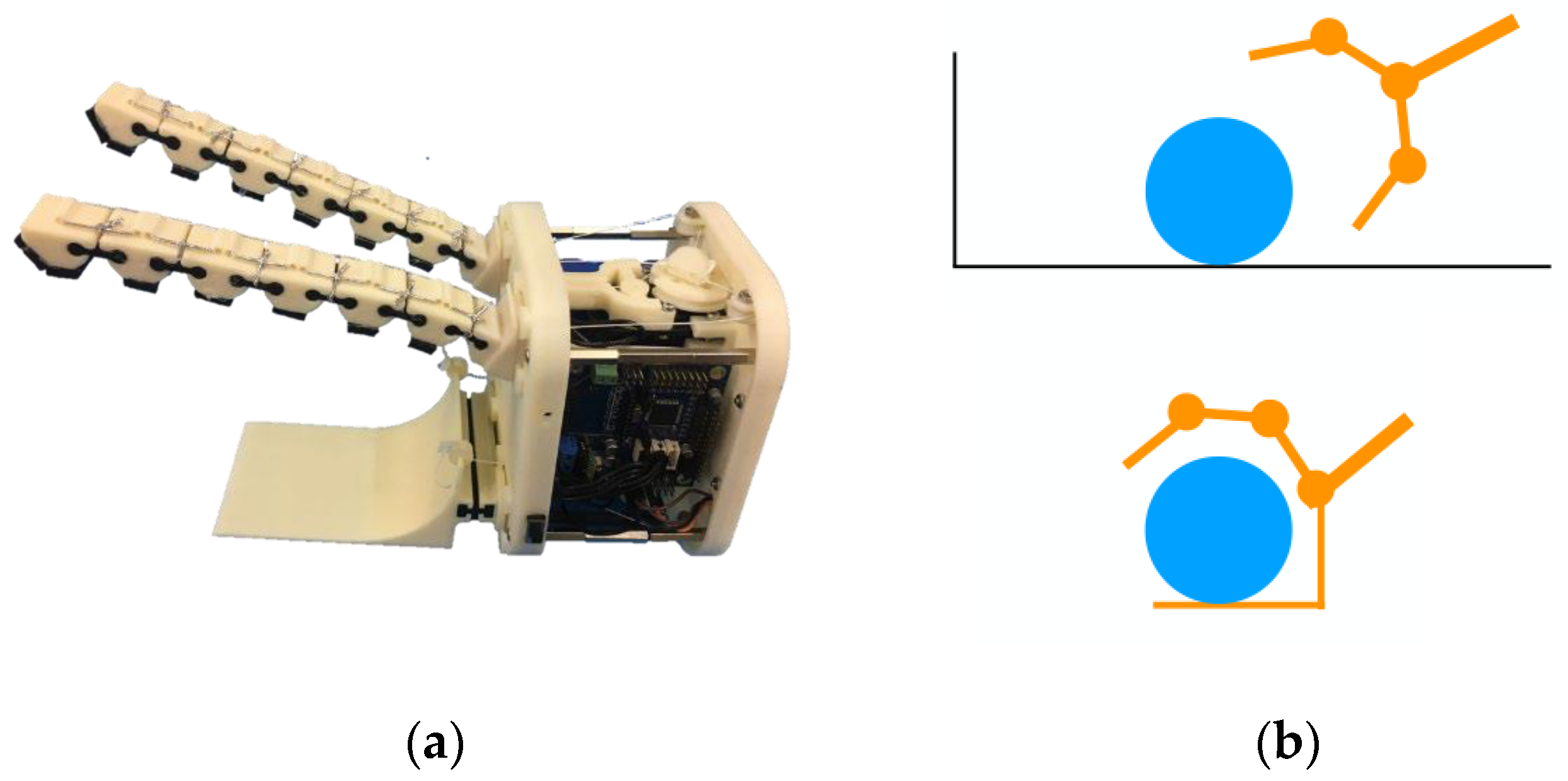
This paper proposes an upgraded version of “The Soft ScoopGripper” [38], a modular, underactuated soft gripper with embodied constraints (Figure 1a). This device is composed of two modular fingers actuated by a single tendon through a differential system and a rigid scoop, which represents the constraint. The rigid modular parts of the fingers are connected together using flexible joints: this configuration allows to have a deformable structure able to adapt to the shape of objects. The rigid scoop, that is connected to the base of the gripper with a flexible prismatic hinge, increases the certainty of the grasp (Figure 1b). An important feature of the gripper is the capability of grasping object not necessary placed on a regular surface, as a plane. Again, the large scoop increases the ability to bear weighty object put on it.
However, using the Soft ScoopGripper, some attention must be paid to its limitations. The grasped objects have to be adequate in term of stiffness to avoid their damage. Use depends on the shape of the objects, and for this reason a flat surface is required. For the gasp of small objects, the user needs a good dexterity to prevent them from falling; in the case of targets with different shapes, versatility and a better reconfiguration is required. According to these issues, this paper proposes many improvements and skills, such as a new design and different movement structure.
3. Design Improvements
3.1. Exploiting Soft Materials
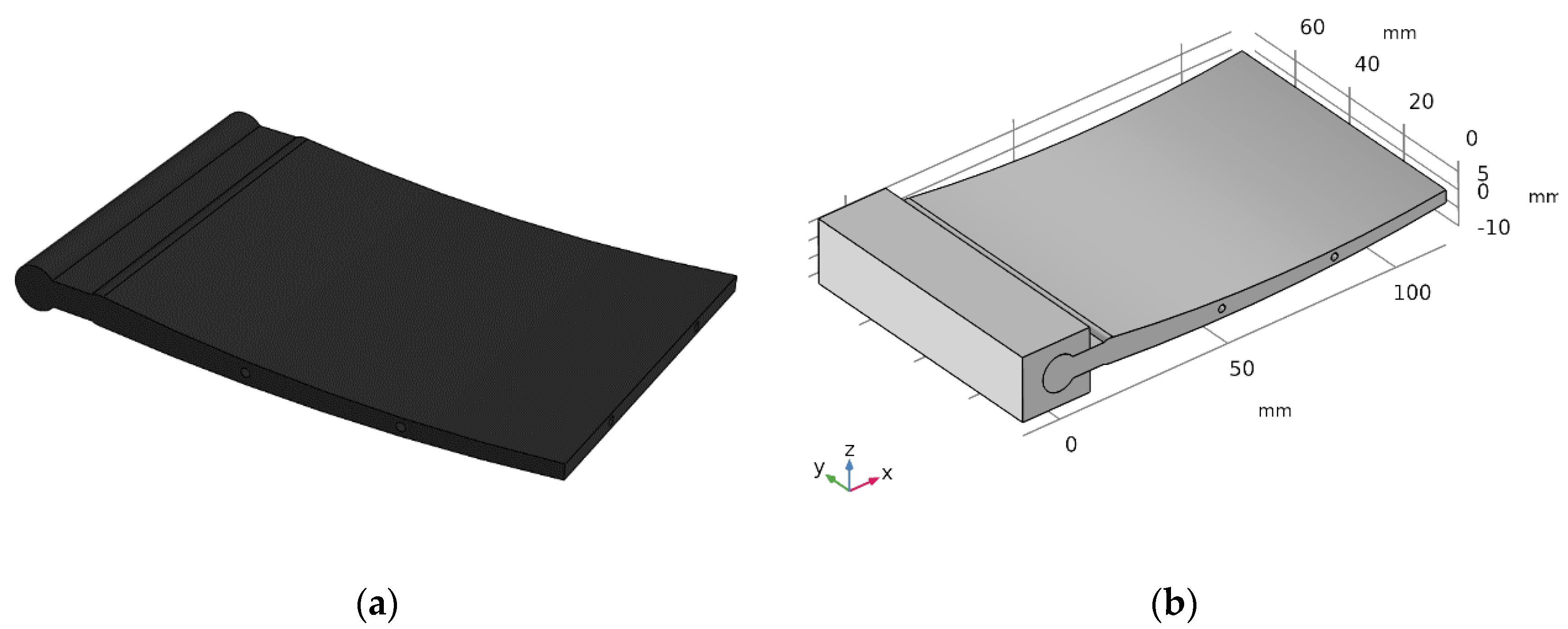
The first improvement proposed in this paper consists in making flexible and active the embedded constraint, that in the first prototype was realized with a rather stiff material (acrylonitrile styrene acrylate, ASA) and could only rotate with respect to the palm, thanks to an elastic connection in the proximal part. This almost rigid realization makes the structure not enough adaptable to the environment uncertainties and to the object. A rigid and thin structure could also provide high contact pressures during the grasp and damage fragile objects (e.g., vegetables, fruits, etc.). As a first improvement of the device, in order to guarantee a higher adaptability, the rigid link has been designed to be realized with a flexible material, in particular TPU was chosen since it is easy to manufacture with standard FDM technologies. TPU is a highly elastic polymer, used for applications that require a good flexibility; this material has a low Young’s modulus value compared to a rigid plastic, such as ASA [41]. Two holes were designed into the single body scoop for the routing of two artificial tendons, from the top to the bottom, needed to actuate the soft hand. Moreover, a pair of holes are planned for inserting cylindrical steel pins, which allow for the recovery of a suitable level of mechanical stiffness in the central part of the structure and allow to lift heavier objects.
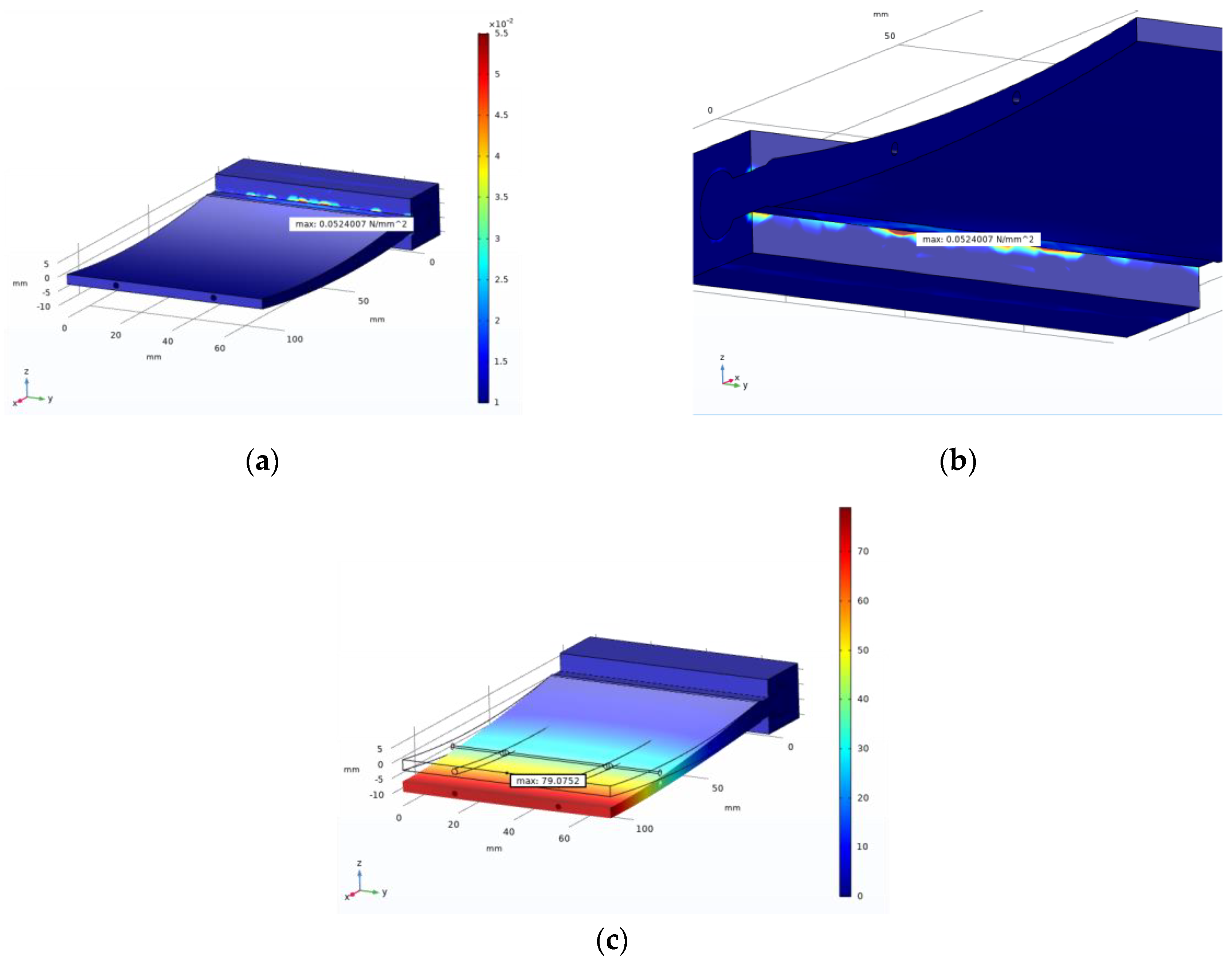
A FEM analysis was realised on the CAD model (Figure 2a,b). This process was used to show the distribution of displacement and stress over the soft structure. The test was realized simulating the grasp and lift of an object with a mass of 2 kg, so a weight force of 19.61 N was considered, which was placed on the end of the scoop. The results (Figure 3a,b) show that there are no high stress areas, with the exception of the contact region between the soft scoop and the support. However, at the distal part of the scoop, a displacement of 79.01 mm was shown (Figure 3c). It is evident that the high flexibility of the employed material would lead to deformations unsuitable for a stable and robust grasp of objects with masses higher than 1–2 kg, which can be assimilated to a weight force of 10–20 N. Four prototypes of the model were 3D printed in TPU material, using different infill percentages. The infill density percentage has an influence on the material mechanical properties, e.g., on the Young modulus (see Table 1) [42].
Therefore, the prototypes were tested on an experimental setup, fixing the support with the scoop to a surface, inserting the artificial tendons and cylindrical pins inside the holes. The test was divided into two parts: analysing the flexion of the scoop by applying a force to the tendons, to simulate the action of the differential mechanism [28], and applying a test weight to the surface to verify the results obtained from the FEM. The results of this test show a larger value of the deformation with respect to the FEM evaluations in the deformation, when a 19.61 N load was applied, the deformation was not measured due to its irregularities and not repeatability. Experimental results also showed some issues with the device actuation. Both the numerical evaluations and the experimental measures showed that this solution presents several limitations: using a part entirely in TPU makes the scoop excessively deformable and unable to stably grasp objects with mass higher than 1–2 kg, and furthermore the actuation system present on the device is not optimal for this design. To proceed with this solution, it would be necessary to review the entire structure, totally overturning the pre-existing system, starting from the positioning of the motors to the entire kinematic chain that is the basis of the robot hand. For this reason, it was decided not to continue with the development of this version and to change the entire structure of the component.
3.2. Modular Elements/1
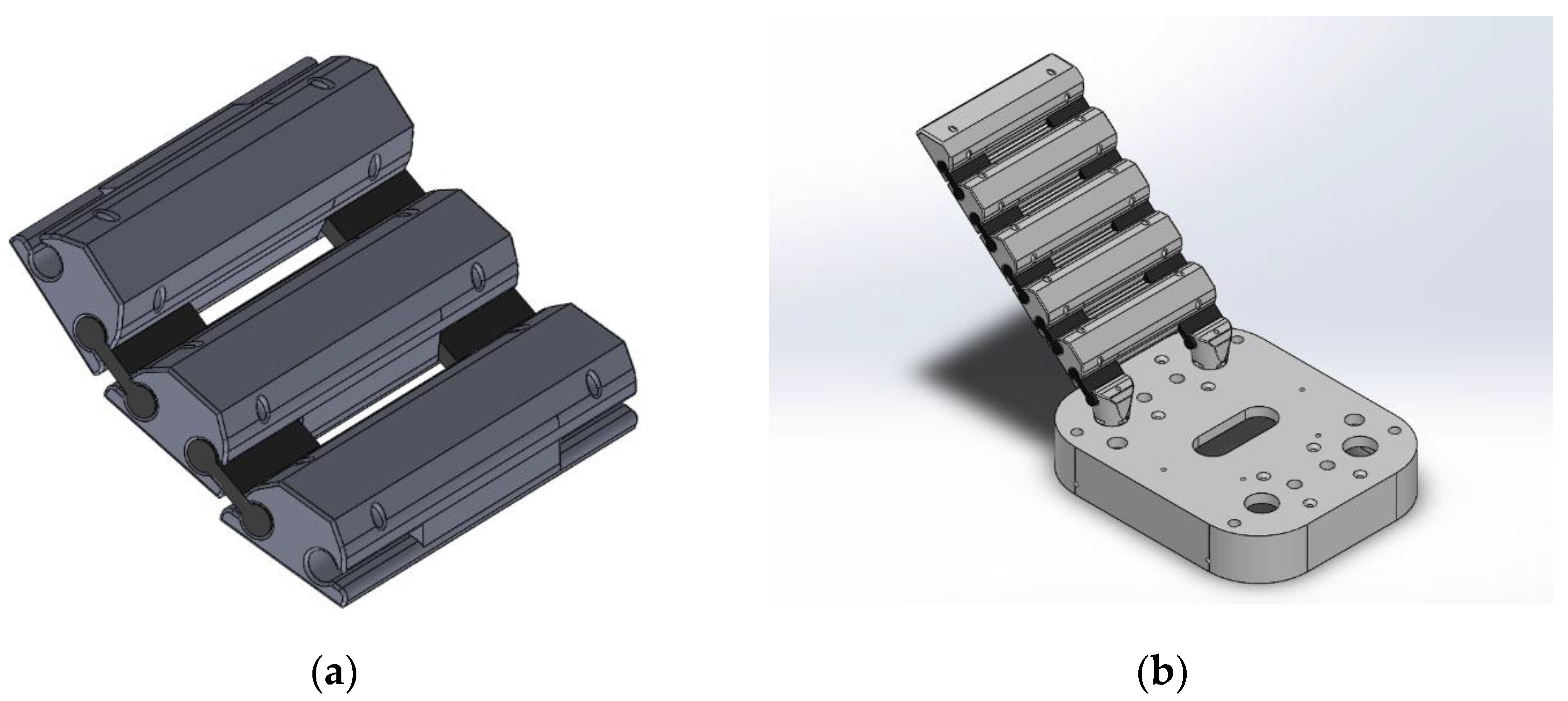
Starting from the Soft ScoopGripper finger structure, the design of the phalanges was changed to make them as much similar as possible to the scoop (see Figure 1a), with a different articulation system. This idea was an extension of the rigid modules realized in ASA, which replace the couple of fingers with a single articulated platform, as shown in (Figure 4a).
This version retains the advantage of the actuation mechanism already present on the original device, redesigning the new paired modules. During grasping, the modules get close each other, forming a continuous surface (Figure 4b), where the object can be leaned. This feature would allow to grasp even small objects. The new modules are 3D printed in ASA and are connected by flexible passive elements realized with TPU. To avoid damage to the objects, TPU strips are placed on the inner face of the modules.
This design allows to overcome some limits of the previous design, but during the development of the prototype, some problems were highlighted, such as the assembly time, that was excessive and not suitable for a device that is intended to be easily customizable and adaptable to task variations. Furthermore, the installation of the TPU profiles on the internal surface of the modules would not guarantee stability, as the glue present appears to have difficulties in adhesion in the long term. These problems encountered in the preliminary prototyping stages have required to develop a new solution which makes the device even more versatile and easier to assemble.
3.3. Modular Elements/2
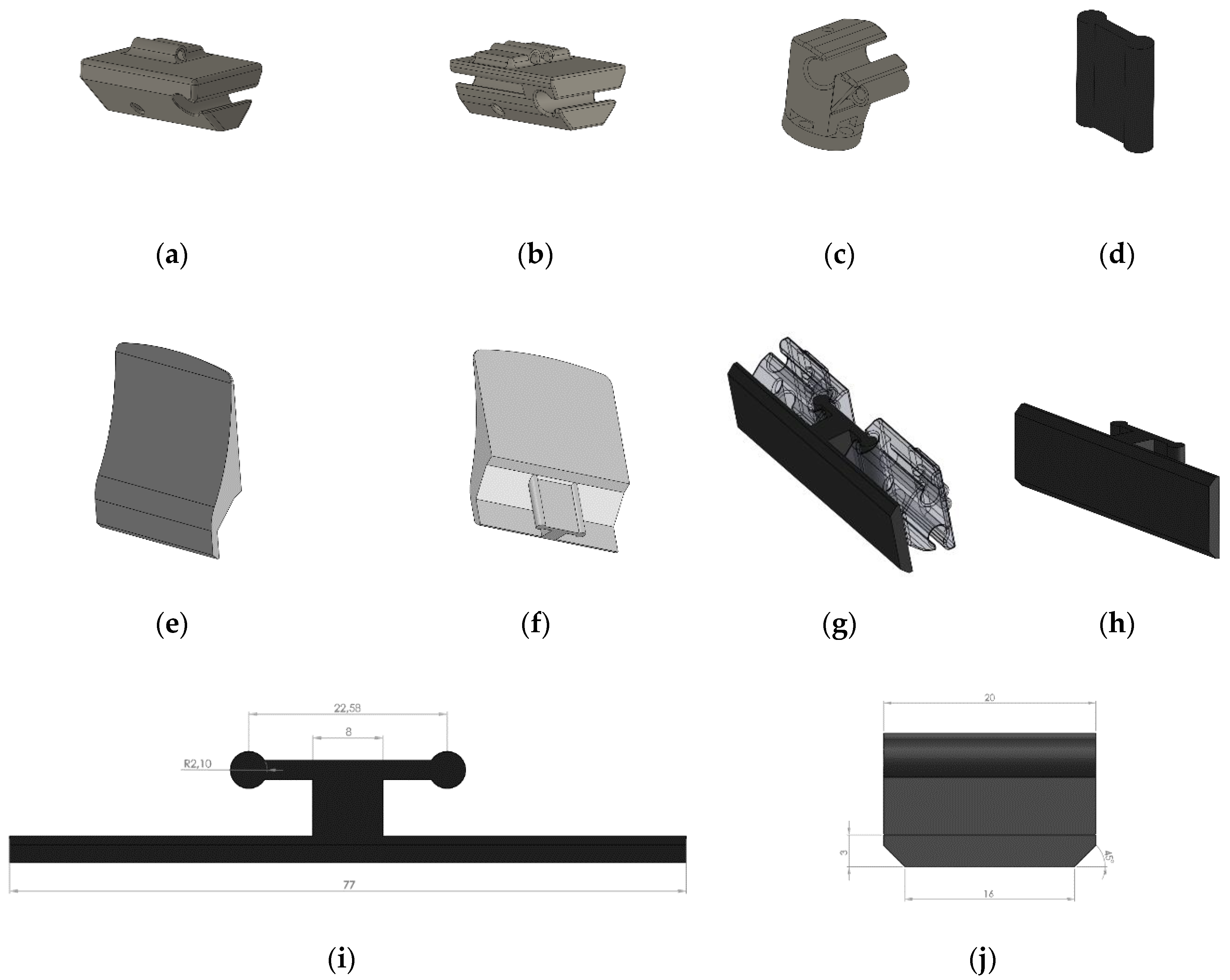
The structure of the third solution was inspired by the fingers of the initial Soft ScoopGripper. In particular a motor fixed on the base of the device rotates a pulley that is connected to an artificial tendon fixed to a slide; the slide is connected to a separate pair of fingers through other two tendons, composed of rigid modules and flexible joints, and fixed on the last module of each single finger. Through the analysis of the Soft ScoopGripper, the proposed solution includes TPU modules inside the new rigid modules, while not compromising the characteristics and the mobility of the device (see Figure 5g).
A flap with a through hole was added on the module to allow the inserting of a TPU module (Figure 5a,b). To ensure stability and at the same time ease of assembly, different types of modules have been provided. All these modules, made of ASA, and are connected each other through elastic TPU joints (Figure 5d). The same profile of the TPU joints was used, thus keeping the hole diameter unchanged; this choice improves further modularity and takes advantage of an already tested and functional design. Once the flap was developed, we proceeded to the design of the TPU module. A classification was performed, dividing them into two types, module A (Figure 5h) and module B (Figure 5e,f). They differ in the function that they will have to perform. Module A will be used on each pair of phalanges, while the end module will be used only on the top of the scoop, where this must have a shape that allows it to be positioned below the object to be manipulated. After some preliminary tests on 3D printed versions of module B, it was decided to use ASA as material for these components.
4. Analysis and Comparison
Numerical Evaluations with FEM Analysis
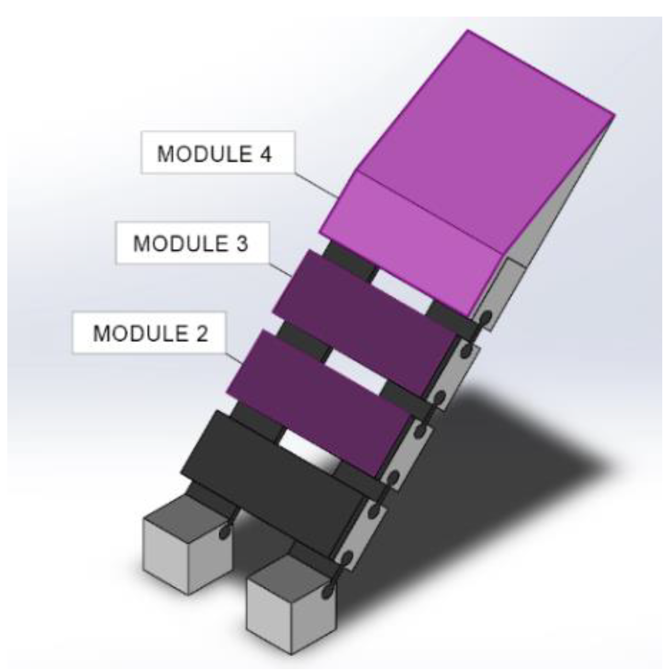
The next phase of this work was the study of static stresses applied to the scoop, using FEM tools. The first step was the definition of a simplified parametric CAD structure similar to the device (see Figure 6). Some details on the model that were not necessary for the analysis were removed to simplify the analysis without influencing the accuracy of the results. The simplifications were introduced for device shape and the elements that compose it, the structure, the constraints and forces used for the kinematic analysis. The upper part of the prototype was examined, holding the two base phalanges using fixed constraints, and applying a roller on the end phalanges: in this way a realistic scoop behavior was emulated. Two different system configurations have been developed: the first, which a constraint was applied to the top of the scoop, to reproduce the behavior when the force was applied by the artificial tendons; the other configuration assesses the resistance of the device when there is no such force, and was obtained by removing the constraint. For both configurations, four tests were carried out with different conditions. A force equal to 19.61 N was applied, equivalent to lifting an object with a mass of 2 kg; this value was chosen to compare the results obtained with the FEM analysis with the ones obtained with the real prototype, which were carried out with objects having a maximum mass of 2 kg. The force was applied to different modules with the same constraint conditions (Table 2), to evaluate the behavior of the device at the different positions that can be assumed by the object taken during grasping. A summary of the results is shown in (Table 3).
5. Prototyping and Testing
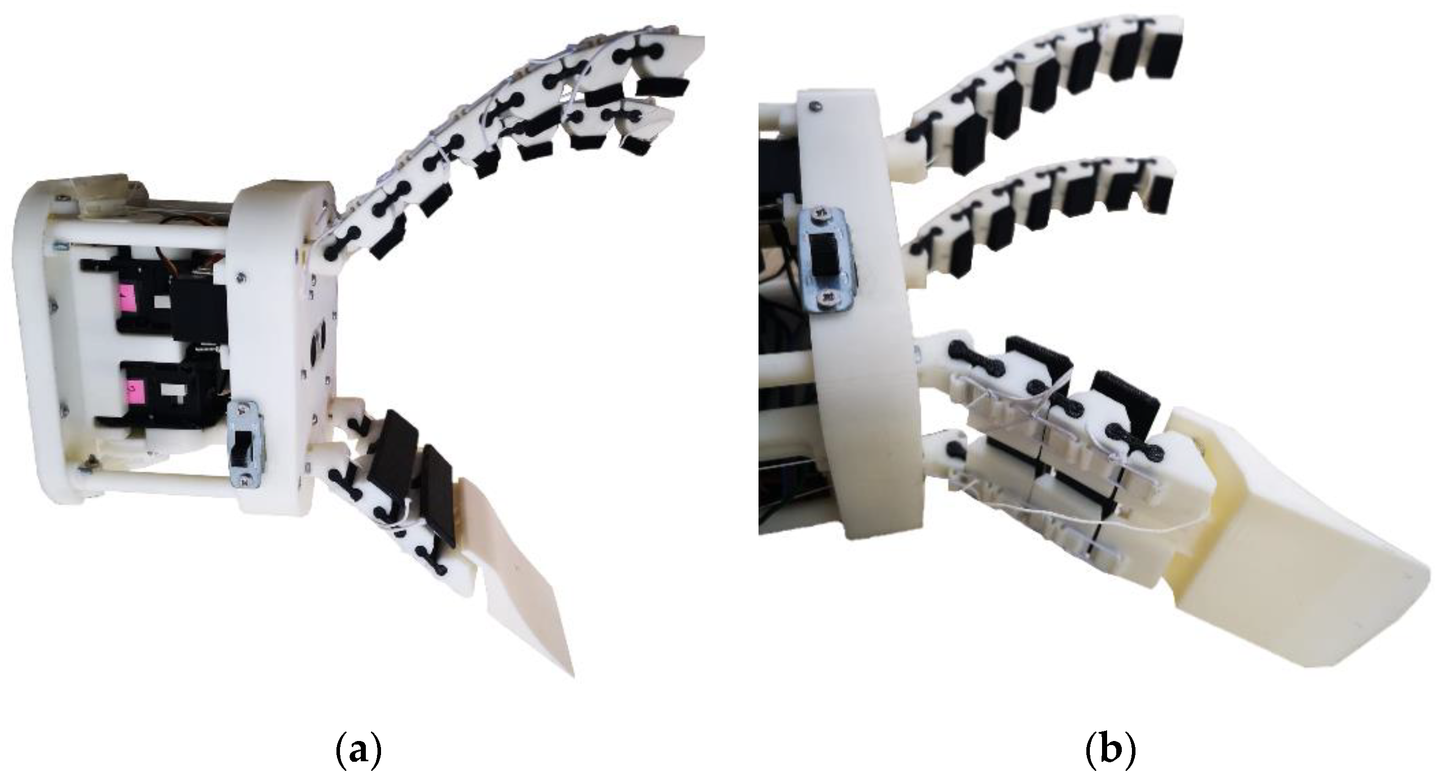
FEM analysis results showed some issues concerning the excessive deformation of the device in action. The choice of using TPU as material for the realization has been identified as the main cause of these issues. The elastic modulus E of this material combined with its difficult printability for FDM technology [45] limits its applicability for the parts that require a high accuracy. Because of these problems, ASA was used to construct the end part of the scoop. This material has different properties with respect to TPU (summarized in Table 4) in particular it is much stiffer and therefore it allows to realize components with a lower flexibility. In addition, ASA is a material that is easier to be printed with respect to TPU, allowing for better resolution and thinner thicknesses. The prototype made with 3D printing additive manufacturing technology is visible in (Figure 7a,b).
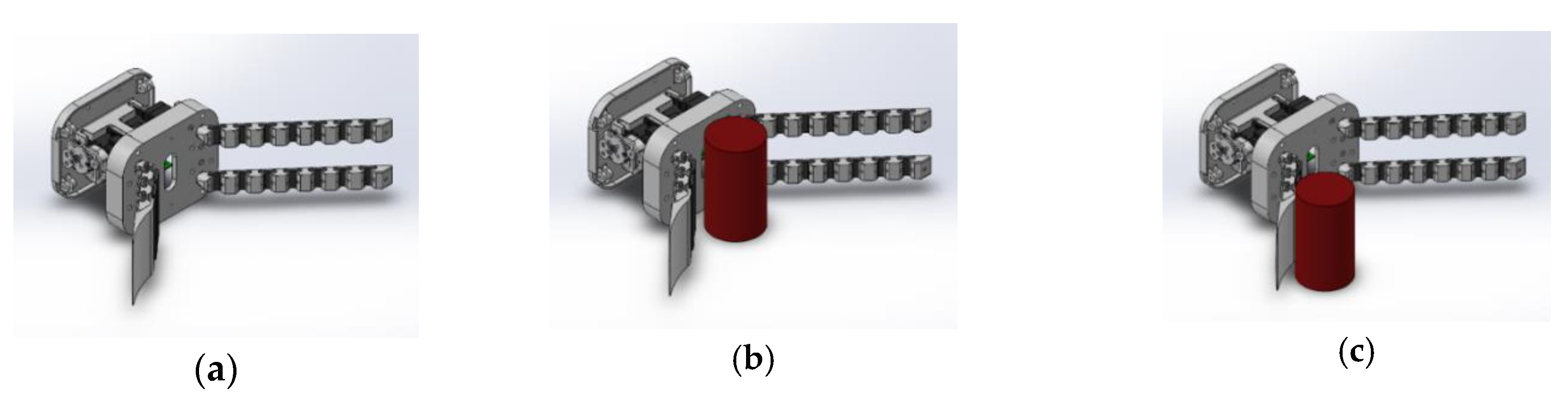
Closure motion: The assembled device was subject to a series of tests to allow the tracking of the closure movements and end-tip trajectories followed by the scoop in a real set up. Three different configurations were considered, which allowed to evaluate the overall behavior of the device: grasping without object (Figure 8a); grasping of an object placed in the center of the scoop (Figure 8b); grasping of an object placed on the outer edge of the scoop (Figure 8c). Comparing the data extracted from the measurements of the different configurations (Table 5), it was possible to describe how the scoop grasps an object, according to its position. The maximum displacement and rotation were found in case 1, where no object was present; this can be explained due to the absence of an obstacle that slows down the movement of the scoop. In case 2, however, the minimum values conducted in this test were found: this could be caused by the higher torque required by the actuator to move the object, which has a lower distance between the point of application of the force and the rotation center, compared to case 3.
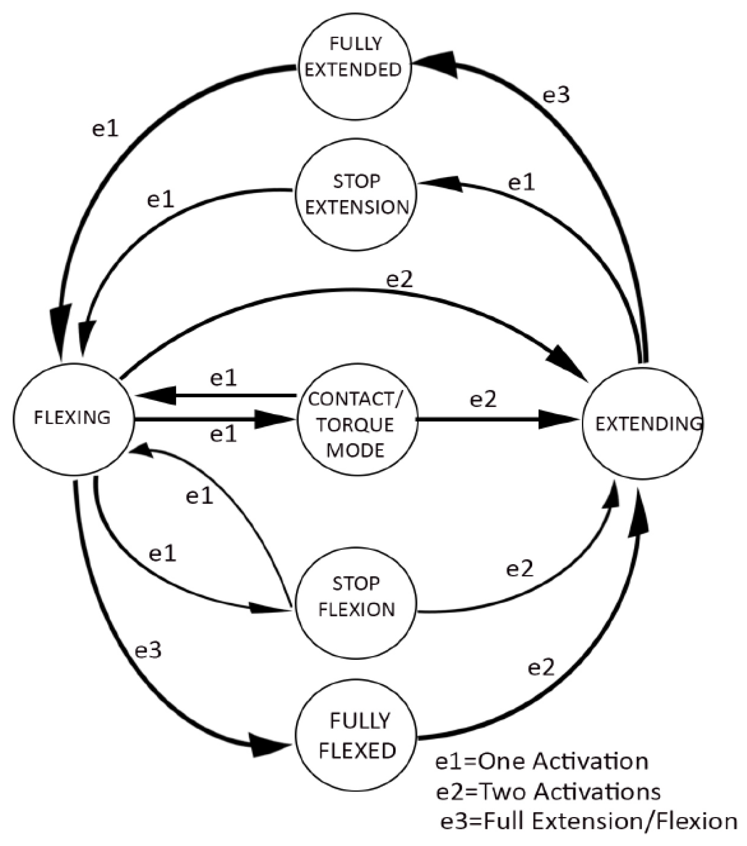
Gripper Control. In addition to the FEM analysis and the study of the trajectory, it was necessary to test the behavior in a real environment to characterize the device. A structure designed for the Soft ScoopGripper [38] was used to analyze all the capabilities of the gripper. This structure is composed of two parts: a handle, molded in ASA, to allow the operator to grab the device easily, and an interface with two buttons, which allow the opening (extension) and closing (flexing) of the scoop, inserted inside the handle itself. Figure 9 reports the finite state machine (FSM) developed to control the gripper, valid for both the finger part and the scoop. The single pressure of the closing button activates the e1 event, which triggers the closing action (flexing) of the fingers and the blade, until contact with an object is detected; upon detection of the presence of the object, by monitoring the torque applied to the electric motor by the microcontroller, the device stops the bending, and passes to the next state, contact/torque mode. In this phase, it is possible to adjust the force applied to the object being gripped by consecutively pressing the relative button, which starts a new state of flexion. This sequence is interrupted when a predetermined threshold is exceeded, which defines the maximum allowable flexion of both the scoop and the finger, called fully flexed. At this stage, the object is completely grasped by the device. The second button of the control interface allows you to activate the extension function, which reduces the moment applied by the electric motor and releases the object. This function can be activated at any time during the process.
Tests with the YCB object set: Following what has already been done for the Soft ScoopGripper [38], tests based on the so-called YCB object and model set and benchmarking were performed [46]. The YCB Object and model set have been designed for facilitating benchmarking in robotic manipulation and they are quite widely adopted in the robotics community to test and compare the grasp and manipulation capabilities of robotic hands and grippers. The availability of an object set for benchmarking allows to compare different types of end-effector, evaluating their grasping characteristics on a heterogeneous group of objects, which differ in shape, weight and stiffness. All the experimentation phases were carried out both for the new version of the scoop and for the previous one, so to have a comparison criterion in the same conditions and with the same samples, to note the differences and the capabilities of the different solutions. To grip different types of objects, it was necessary to apply a reconfiguration of the fingers: the mechanical system designed allows to rotate the components at the base of the two fingers to allow grasping objects having a cylindrical symmetry, without having to rotate the device (Table 6, case 3). Using a scoop reduces the force required on the fingers to hold the object; the scoop will take most of the weight, while the fingers will keep the object stable, to not lose the grasp. The comparison table between the two devices shows how the new version, despite a greater compliance given by a less rigid structure, allows to support heavy objects (Table 6, case 2), also adapting to the shapes of objects with non-flat surfaces (Table 6, cases 1 and 3). This feature has shown greater safety in the grip compared to the previous version. In Table 6 (case 4), it is shown that the contact surface formed by the TPU modules, with greater flexibility than the rigid ASA scoop, limits the risk of damage.
6. Conclusions and Future Work
6.1. Conclusions
Table 7 summarizes a qualitative comparison relating to the limits of the Soft ScoopGripper previously reported, analyzing which of these had been overcome by the proposed prototypes. The prototype 3 can overcome all the limits encountered in the original project. Indeed, in prototype 1, the main problems have not been sufficiently resolved, due to the excessive deformability of the chosen material (TPU) and the implementation system, with little improvement possibilities, due to the limits shown. Prototype 2 was used as a basic idea for the development of the prototype 3, as it provided the opportunity to showcase the potential of the modular design, despite not having accomplished a real experimentation phase.
In summary, prototype 3, that uses a modular system having a high ability to adapt to the object, shows good versatility and the possibility of reconfiguration. This allows to move from a structure made up of two pairs of fingers to one having a couple of fingers and a scoop in an assembly time of a few minutes, thanks to the developed interchangeable modules. Furthermore, as visible from the comparative scheme (Table 6), despite the use of a yielding structure and with greater deformability, the grasping and sealing capacity of the gripping objects is unchanged compared to the Soft ScoopGripper.
6.2. Future Work
The studies carried out so far have mainly focused on the design and choice of the most suitable device. Future studies will be used to perform an experimental quantitative characterization of the gripper. Furthermore, tests will be carried out according to ISO 14539 standard to validate the work.
Currently, we are also identifying the suitable application fields for this type of gripper. The ability to manipulate objects by simulating the action exerted by a human hand is required in those areas where the integrity of the product itself and that of the operator performing the task prevail. Two fields have been identified, namely agri-food and waste industry. In both areas, grasping ability and not damaging the object are required, and this device is suitable for this task. Therefore, we are working to replicate a convey-belt system on a laboratory scale to verify grasping capabilities in a more complex environment. Another part of the research will be the study of other types of materials and manufacturing for the realization of gripper components.
Author Contributions
G.M.A. contributed to investigation, conceptualization, data curation and writing (original draft, review & editing); M.C.V. contributed to supervision and writing (original draft); G.S. contributed to conceptualization and writing (review & editing); M.M. contributed to methodology and supervision. All authors have read and agreed to the published version of the manuscript.
Funding
The work was partially funded by “Fondo Ricerca di Base 2019, dell’Università degli Studi di Perugia” for the project:” Studio di base per tecnologia aptica: modellazione teorica e validazione sperimentale del toccare umano in 3D” and by project INBOTS CSA, Inclusive Robotics for a better Society, Program H2020-ICT-2017-1; grant agreement n. 780073.
Conflicts of Interest
The authors declare no conflict of interest.
References
- Mason, M.T.; Salisbury, J.K., Jr. Robot Hands and the Mechanics of Manipulation; The MIT Press: Cambridge, MA, USA, 1985. [Google Scholar]
- Carbone, G. Grasping in Robotics; Springer: Berlin/Heidelberg, Germany, 2012; Volume 10. [Google Scholar]
- Melchiorri, C.; Kaneko, M. Robot Hands. In Springer Handbook of Robotics; Siciliano, B., Khatib, O., Eds.; Springer: Berlin/Heidelberg, Germany, 2008; pp. 345–360. [Google Scholar] [CrossRef]
- Shintake, J.; Cacucciolo, V.; Floreano, D.; Shea, H. Soft robotic grippers. Adv. Mater. 2018, 30, 1707035. [Google Scholar] [CrossRef] [PubMed] [Green Version]
- Haidegger, T.; Galambos, P.; Rudas, I.J. Robotics 4.0–Are we there yet? In Proceedings of the 2019 IEEE 23rd International Conference on Intelligent Engineering Systems (INES), Gödöllő, Hungary, 25–27 April 2019; pp. 000117–000124. [Google Scholar]
- Kehoe, B.; Berenson, D.; Goldberg, K. Toward cloud-based grasping with uncertainty in shape: Estimating lower bounds on achieving force closure with zero-slip push grasps. In Proceedings of the 2012 IEEE International Conference on Robotics and Automation, St Paul, MN, USA, 14–18 May 2012; pp. 576–583. [Google Scholar]
- Takács, K.; Mason, A.; Christensen, L.B.; Haidegger, T. Robotic Grippers for Large and Soft Object Manipulation. In Proceedings of the IEEE 20th International Symposium on Computational Intelligence and Informatics (CINTI 2020), Budapest, Hungary, 5–7 November 2020. [Google Scholar]
- Fukaya, N.; Toyama, S.; Asfour, T.; Dillmann, R. Design of the TUAT/Karlsruhe humanoid hand. In Proceedings of the 2000 IEEE/RSJ International Conference on Intelligent Robots and Systems (IROS 2000) (Cat. No. 00CH37113), Takamatsu, Japan, 31 October–5 November 2000; pp. 1754–1759. [Google Scholar]
- Butterfaß, J.; Grebenstein, M.; Liu, H.; Hirzinger, G. DLR-Hand II: Next generation of a dextrous robot hand. In Proceedings of the 2001 ICRA. IEEE International Conference on Robotics and Automation (Cat. No. 01CH37164), Seoul, Korea, 21–26 May 2001; pp. 109–114. [Google Scholar]
- Martin, E.; Desbiens, A.L.; Laliberté, T.; Gosselin, C. SARAH hand used for space operation on STVF robot. In Proceedings of the International Conference on Intelligent Manipulation and Grasping, Genova, Italy, 1–2 July 2004; pp. 279–284. [Google Scholar]
- Roccella, S.; Carrozza, M.C.; Cappiello, G.; Dario, P.; Cabibihan, J.-J.; Zecca, M.; Miwa, H.; Itoh, K.; Marsumoto, M. Design, fabrication and preliminary results of a novel anthropomorphic hand for humanoid robotics: RCH-1. In Proceedings of the 2004 IEEE/RSJ International Conference on Intelligent Robots and Systems (IROS)(IEEE Cat. No. 04CH37566), Sendai, Japan, 28 September–2 October 2004; pp. 266–271. [Google Scholar]
- Dechev, N.; Cleghorn, W.; Naumann, S. Multiple finger, passive adaptive grasp prosthetic hand. Mech. Mach. Theory 2001, 36, 1157–1173. [Google Scholar] [CrossRef]
- Raparelli, T.; Mattiazzo, G.; Mauro, S.; Velardocchia, M. Design and development of a pneumatic anthropomorphic hand. J. Robot. Syst. 2000, 17, 1–15. [Google Scholar] [CrossRef]
- Maffiodo, D.; Raparelli, T. Three-fingered gripper with flexure hinges actuated by shape memory alloy wires. Int. J. Autom. Technol. 2017, 11, 355–360. [Google Scholar] [CrossRef]
- Niola, V.; Penta, F.; Rossi, C.; Savino, S. An underactuated mechanical hand: Theoretical studies and prototyping. Int. J. Mech. Control 2015, 16, 11–19. [Google Scholar]
- Cosenza, C.; Niola, V.; Savino, S. Analytical study for the capability implementation of an underactuated three-finger hand. In New Trends in Medical and Service Robotics; Springer: Berlin/Heidelberg, Germany, 2019; pp. 161–168. [Google Scholar]
- Niola, V.; Rossi, C.; Savino, S.; Timpone, F. Study of an underactuated mechanical finger driven by tendons. Int. J. Autom. Technol. 2017, 11, 344–354. [Google Scholar] [CrossRef]
- Maffiodo, D.; Raparelli, T. Comparison among different modular SMA actuated flexible fingers. In Advances in Italian Mechanism Science; Springer: Cham, Switzerland, 2018; pp. 324–331. [Google Scholar]
- Carbone, G.; Rossi, C.; Savino, S. Performance comparison between FEDERICA hand and LARM hand. Int. J. Adv. Robot. Syst. 2015, 12, 90. [Google Scholar] [CrossRef]
- Kobayashi, H.; Hyodo, K.; Ogane, D. On tendon-driven robotic mechanisms with redundant tendons. Int. J. Robot. Res. 1998, 17, 561–571. [Google Scholar] [CrossRef]
- Laliberté, T.; Gosselin, C.M. Underactuation in space robotic hands. In Proceedings of the Sixth International Symposium on Artificial Intelligence, Robotics and Automation in Space ISAIRAS: A New Space Odyssey, St-Hubert, QC, Canada, 18–22 June 2001. [Google Scholar]
- Hussain, I.; Salvietti, G.; Spagnoletti, G.; Prattichizzo, D. The soft-sixthfinger: A wearable emg controlled robotic extra-finger for grasp compensation in chronic stroke patients. IEEE Robot. Autom. Lett. 2016, 1, 1000–1006. [Google Scholar] [CrossRef] [Green Version]
- Laliberte, T.; Birglen, L.; Gosselin, C. Underactuation in robotic grasping hands. Mach. Intell. Robot. Control 2002, 4, 1–11. [Google Scholar]
- Ceccarelli, M.; Tavolieri, C.; Lu, Z. Design considerations for underactuated grasp with a one DOF anthropomorphic finger mechanism. In Proceedings of the 2006 IEEE/RSJ International Conference on Intelligent Robots and Systems, Beijing, China, 9–15 October 2006; pp. 1611–1616. [Google Scholar]
- Wu, L.; Carbone, G.; Ceccarelli, M. Designing an underactuated mechanism for a 1 active DOF finger operation. Mech. Mach. Theory 2009, 44, 336–348. [Google Scholar] [CrossRef]
- Carbone, G.; Yao, S.; Ceccarelli, M.; Lu, Z. Design and simulation of a new underactuated mechanism for LARM hand. Robotica 2017, 35, 483–497. [Google Scholar]
- Hussain, I.; Malvezzi, M.; Gan, D.; Iqbal, Z.; Seneviratne, L.; Prattichizzo, D.; Renda, F. Compliant gripper design, prototyping, and modeling using screw theory formulation. Int. J. Robot. Res. 2020, 0278364920947818. [Google Scholar]
- Malvezzi, M.; Iqbal, Z.; Valigi, M.C.; Pozzi, M.; Prattichizzo, D.; Salvietti, G. Design of Multiple Wearable Robotic Extra Fingers for Human Hand Augmentation. Robotics 2019, 8, 102. [Google Scholar] [CrossRef] [Green Version]
- Malvezzi, M.; Valigi, M.C.; Salvietti, G.; Iqbal, Z.; Hussain, I.; Prattichizzo, D. Design criteria for wearable robotic extra–fingers with underactuated modular structure. In Proceedings of the International Conference of IFToMM ITALY, Naples, Italy, 29–30 November 2018; pp. 509–517. [Google Scholar]
- Birglen, L.; Gosselin, C.M. Force analysis of connected differential mechanisms: Application to grasping. Int. J. Robot. Res. 2006, 25, 1033–1046. [Google Scholar] [CrossRef]
- Zappatore, G.A.; Reina, G.; Messina, A. Analysis of a highly underactuated robotic hand. Int. J. Mech. Control 2017, 18, 17–24. [Google Scholar]
- Birglen, L.; Gosselin, C.M. On the force capability of underactuated fingers. In Proceedings of the 2003 IEEE International Conference on Robotics and Automation (Cat. No. 03CH37422), Taipei, Taiwen, 14–19 October 2003; pp. 1139–1145. [Google Scholar]
- Massa, B.; Roccella, S.; Carrozza, M.C.; Dario, P. Design and development of an underactuated prosthetic hand. In Proceedings of the 2002 IEEE international conference on robotics and automation (Cat. No. 02CH37292), Washington, DC, USA, 11–15 May 2002; pp. 3374–3379. [Google Scholar]
- Baril, M.; Laliberte, T.; Gosselin, C.; Routhier, F. On the design of a mechanically programmable underactuated anthropomorphic prosthetic gripper. J. Mech. Des. 2013, 135. [Google Scholar] [CrossRef]
- Kontoudis, G.P.; Liarokapis, M.V.; Zisimatos, A.G.; Mavrogiannis, C.I.; Kyriakopoulos, K.J. Open-source, anthropomorphic, underactuated robot hands with a selectively lockable differential mechanism: Towards affordable prostheses. In Proceedings of the 2015 IEEE/RSJ International Conference on Intelligent Robots and Systems (IROS), Hamburg, Germany, 28 September–2 October 2015; pp. 5857–5862. [Google Scholar]
- Eppner, C.; Deimel, R.; Alvarez-Ruiz, J.; Maertens, M.; Brock, O. Exploitation of environmental constraints in human and robotic grasping. Int. J. Robot. Res. 2015, 34, 1021–1038. [Google Scholar] [CrossRef] [Green Version]
- Heinemann, F.; Puhlmann, S.; Eppner, C.; Élvarez-Ruiz, J.; Maertens, M.; Brock, O. A taxonomy of human grasping behavior suitable for transfer to robotic hands. In Proceedings of the 2015 IEEE International Conference on Robotics and Automation (ICRA), Seattle, WA, USA, 25–30 May 2015. [Google Scholar]
- Salvietti, G.; Iqbal, Z.; Malvezzi, M.; Eslami, T.; Prattichizzo, D. Soft hands with embodied constraints: The soft scoopgripper. In Proceedings of the 2019 International Conference on Robotics and Automation (ICRA), Montreal, QC, Canada, 20–24 May 2019; pp. 2758–2764. [Google Scholar]
- Shen, Y.; Salemi, W.; Rus, B.; Moll, D.; Lipson, M. Modular self-reconfigurable robot systems. IEEE Robot. Autom. Mag. 2007, 14, 43–52. [Google Scholar]
- Prattichizzo, D.; Malvezzi, M.; Hussain, I.; Salvietti, G. The sixth-finger: A modular extra-finger to enhance human hand capabilities. In Proceedings of the 23rd IEEE International Symposium on Robot and Human Interactive Communication, Edinburgh, UK, 25–29 August 2014; pp. 993–998. [Google Scholar]
- Reppel, T.; Weinberg, K. Experimental determination of elastic and rupture properties of printed ninjaflex. Tech. Mech. Sci. J. Fundam. Appl. Eng. Mech. 2018, 38, 104–112. [Google Scholar]
- Hussain, I.; Salvietti, G.; Malvezzi, M.; Prattichizzo, D. On the role of stiffness design for fingertip trajectories of underactuated modular soft hands. In Proceedings of the 2017 IEEE International Conference on Robotics and Automation (ICRA), Singapore, 29 May–3 June 2017; pp. 3096–3101. [Google Scholar]
- Logozzo, S.; Valigi, M.C.; Canella, G. Advances in optomechatronics: An automated tilt-rotational 3D scanner for high-quality reconstructions. Photonics 2018, 5, 42. [Google Scholar] [CrossRef] [Green Version]
- Valigi, M.C.; Logozzo, S.; Canella, G. A new automated 2 DOFs 3D desktop optical scanner. In Advances in Italian Mechanism Science; Springer: Berlin/Heidelberg, Germany, 2017; pp. 231–238. [Google Scholar]
- Harris, C.G.; Jursik, N.J.; Rochefort, W.E.; Walker, T.W. Additive Manufacturing with Soft TPU—Adhesion Strength in Multimaterial Flexible Joints. Front. Mech. Eng. 2019, 5, 37. [Google Scholar] [CrossRef] [Green Version]
- Calli, B.; Walsman, A.; Singh, A.; Srinivasa, S.; Abbeel, P.; Dollar, A.M. Benchmarking in manipulation research: The YCB object and model set and benchmarking protocols. arXiv 2015, arXiv:1502.03143. [Google Scholar]
Figure 1.
The Soft ScoopGripper prototype presented in [38] (a) and the main idea of soft hands with embodied constraints (b). (© 2019 IEEE)
Figure 1.
The Soft ScoopGripper prototype presented in [38] (a) and the main idea of soft hands with embodied constraints (b). (© 2019 IEEE)

Figure 2.
(a) A 3D view of a scoop made of soft material. (b) The FEM model for the simulation of the static stress over the scoop.
Figure 2.
(a) A 3D view of a scoop made of soft material. (b) The FEM model for the simulation of the static stress over the scoop.

Figure 3.
Results of the FEM analysis on the flexible version, a load of 19.61 N on the tip edge was applied. (a) equivalent Von Mises stress distribution and (b) detail area; (c) overall displacement.
Figure 3.
Results of the FEM analysis on the flexible version, a load of 19.61 N on the tip edge was applied. (a) equivalent Von Mises stress distribution and (b) detail area; (c) overall displacement.

Figure 4.
Modular coupled fingers: (a) The scoop is substituted by an articulated platform with the same modular structure of the finger, and larger rigid elements; (b) The prototype CAD design.
Figure 4.
Modular coupled fingers: (a) The scoop is substituted by an articulated platform with the same modular structure of the finger, and larger rigid elements; (b) The prototype CAD design.

Figure 5.
Modular elements that compose the gripper: (a) Ending module, (b) middle module and (c) starting module of the robotic finger of the gripper. (d) Flexible joint placed between a pair of modules. (e) Module B, front and (f) back view. (g) Two middle modules joined module A. (h) Module A, (i) top and (j) side view.

Figure 6.
Simplified 3D model for FEM analysis.

Figure 7.
The soft gripper with modular embedded constraints prototype (a) and a detail of the modular scoop (b).
Figure 7.
The soft gripper with modular embedded constraints prototype (a) and a detail of the modular scoop (b).

Figure 8.
Three different configurations employed to study the movements of the device: (a) grasping without object. (b) Grasping of an object placed in the center of the scoop. (c) Grasping of an object placed on the outer edge of the scoop.
Figure 8.
Three different configurations employed to study the movements of the device: (a) grasping without object. (b) Grasping of an object placed in the center of the scoop. (c) Grasping of an object placed on the outer edge of the scoop.

Figure 9.
Finite State Machine for gripper control.


Table 1.
Four different infill density percentages applied during the 3D printing process and the corresponding variation of Young’s modulus E, that affect the stiffness and the flexibility of the scoop.
Table 1.
Four different infill density percentages applied during the 3D printing process and the corresponding variation of Young’s modulus E, that affect the stiffness and the flexibility of the scoop.
| Prototype | Infill Percentage % | E [MPa] |
|---|---|---|
| #1 | 30 | 1.38 |
| #2 | 50 | 2.07 |
| #3 | 70 | 6.53 |
| #4 | 90 | 9.45 |
Table 2.
Configuration of force application.
| Case | Modules to which Force is Applied |
|---|---|
| 1 | Modules 2 and 3 |
| 2 | Module 3 |
| 3 | Modules 3 and 4 |
| 4 | Module 4 |
Table 3.
Results of FEM analysis performed in the two different configurations.
| Gripper with No Constraint | Gripper with Constraint | |||||
|---|---|---|---|---|---|---|
| Case | Analysis | Min Value | Max Value | Analysis | Min Value | Max Value |
| 1 | Displacement | 0 mm | 22.3 mm | Displacement | 0 mm | 0.507 mm |
| Von Mises Stress | 5.50 × 10⁻⁴ N/mm2 | 22.7 N/mm2 | Von Mises Stress | 6.49 × 10⁻⁵ N/mm2 | 3.2 N/mm2 | |
| 2 | Displacement | 0 mm | 16.6 mm | Displacement | 0 mm | 0.604 mm |
| Von Mises Stress | 3.48 × 10⁻⁴ N/mm2 | 15.3 N/mm2 | Von Mises Stress | 6.66 × 10⁻⁵ N/mm2 | 2.82 N/mm2 | |
| 3 | Displacement | 0 mm | 22.3 mm | Displacement | 0 mm | 0.419 mm |
| Von Mises Stress | 8.13 × 10⁻⁴ N/mm2 | 27.4 N/mm2 | Von Mises Stress | 2.19 × 10⁻⁵ N/mm2 | 1.76 N/mm2 | |
| 4 | Displacement | 0 mm | 33.7 mm | Displacement | 0 mm | 22.3 mm |
| Von Mises Stress | 5.95 × 10⁻⁴ N/mm2 | 18.9 N/mm2 | Von Mises Stress | 5.90 × 10⁻⁵ N/mm2 | 1.96 N/mm2 | |
Table 4.
Mechanical properties of the materials under study.
| Material Properties | ASA | TPU |
|---|---|---|
| Elastic modulus (E) | 29 N/mm2 | 15.2 N/mm2 |
| Poisson ratio | 1.03 | 1.29 |
| Density | 1070 kg/m3 | 1200 kg/m3 |
Table 5.
Data obtained from the analysis of the rotation and translation when the scoop is grasping.
Table 5.
Data obtained from the analysis of the rotation and translation when the scoop is grasping.
| Configuration | Rotations [deg] | Translations [mm] | |
|---|---|---|---|
| Z | Y | ||
| 1 | No object | 73.5 | 64.3 |
| 2 | Center | 53.9 | 49.3 |
| 3 | Outer edge | 72.2 | 59.7 |
Table 6.
Comparison between different object grasped with the gripper.
| Case 1 | Case 2 | Case 3 | Case 4 | |
|---|---|---|---|---|
| A |  |  |  |  |
| B |  |  |  |  |
Table 7.
Summary comparison between three different prototypes.
| Soft Scoop Gripper Properties | Prototypes | ||
|---|---|---|---|
| 1 | 2 | 3 | |
| Capability to adapting to non-flat rigid surfaces, where the stiffness of the material and the scoop shape make it difficult to insert it under an object. | No | Yes | Yes |
| Avoiding damage of grabbed objects, always due to the stiffness of the material of which the scoop is made. | Yes | Yes | Yes |
| Enough adaptability to the shape of objects; if the shape of the object does not have a flat surface, the grip is almost exclusively performed by the fingers, and the scoop works as a constraint only. | Yes | Yes | Yes |
| Good mobility of the scoop; no limited movement, which does allow a secure grip if the device is trying to grasp small objects. | No | Yes | Yes |
| Capability to selecting a particular target within a heterogeneous mix of different shape objects, as extracting a ball from inside a basket of toys. | No | Yes | Yes |
| Versatile and easily reconfigurable. | No | No | Yes |
Publisher’s Note: MDPI stays neutral with regard to jurisdictional claims in published maps and institutional affiliations. |
© 2020 by the authors. Licensee MDPI, Basel, Switzerland. This article is an open access article distributed under the terms and conditions of the Creative Commons Attribution (CC BY) license (http://creativecommons.org/licenses/by/4.0/).
Share and Cite
MDPI and ACS Style
Achilli, G.M.; Valigi, M.C.; Salvietti, G.; Malvezzi, M. Design of Soft Grippers with Modular Actuated Embedded Constraints. Robotics 2020, 9, 105. https://0-doi-org.brum.beds.ac.uk/10.3390/robotics9040105
AMA Style
Achilli GM, Valigi MC, Salvietti G, Malvezzi M. Design of Soft Grippers with Modular Actuated Embedded Constraints. Robotics. 2020; 9(4):105. https://0-doi-org.brum.beds.ac.uk/10.3390/robotics9040105
Chicago/Turabian StyleAchilli, Gabriele Maria, Maria Cristina Valigi, Gionata Salvietti, and Monica Malvezzi. 2020. "Design of Soft Grippers with Modular Actuated Embedded Constraints" Robotics 9, no. 4: 105. https://0-doi-org.brum.beds.ac.uk/10.3390/robotics9040105
Note that from the first issue of 2016, this journal uses article numbers instead of page numbers. See further details here.