Preliminary Work on a Virtual Reality Interface for the Guidance of Underwater Robots


IRS-Lab, Computer Science and Engineering Department, Jaume I University, Avd. Sos Baynat s/n, 12071 Castellón de la Plana, Spain
*
Author to whom correspondence should be addressed.
Robotics 2020, 9(4), 81; https://0-doi-org.brum.beds.ac.uk/10.3390/robotics9040081
Submission received: 16 July 2020
/
Revised: 16 September 2020
/
Accepted: 27 September 2020
/
Published: 2 October 2020
(This article belongs to the Special Issue Advances in Underwater Robotics)
Abstract
:The need for intervention in underwater environments has increased in recent years but there is still a long way to go before AUVs (Autonomous Underwater Vehicles) will be able to cope with really challenging missions. Nowadays, the solution adopted is mainly based on remote operated vehicle (ROV) technology. These ROVs are controlled from support vessels by using unnecessarily complex human–robot interfaces (HRI). Therefore, it is necessary to reduce the complexity of these systems to make them easier to use and to reduce the stress on the operator. In this paper, and as part of the TWIN roBOTs for the cooperative underwater intervention missions (TWINBOT) project, we present an HRI (Human-Robot Interface) module which includes virtual reality (VR) technology. In fact, this contribution is an improvement on a preliminary study in this field also carried out, by our laboratory. Hence, having made a concerted effort to improve usability, the HRI system designed for robot control tasks presented in this paper is substantially easier to use. In summary, reliability and feasibility of this HRI module have been demonstrated thanks to the usability tests, which include a very complete pilot study, and guarantee much more friendly and intuitive properties in the final HRI-developed module presented here.
1. Introduction
Nowadays, underwater tasks, like the maintenance of underwater equipment or the deployment and recovery of benthic stations, are addressed using manned submersibles or work-class remote operated vehicles (ROVs) equipped with teleoperated arms. The state-of-the-art in the field includes virtual reality (VR) in the form of a simple control and survey [1] and it is already on the market. Some companies offer inspecting and monitoring ROVs, like Qysea (https://www.qysea.com/products/fifish-v6/) or Deep Trekker (https://www.deeptrekker.com) while others include arm capability, like ROV innovations (https://www.rovinnovations.com/).
While commercially available autonomous underwater vehicles are regularly used in survey missions, there is a new set of tasks that demand intervention capabilities, because of the increased level of complexity involved [2]. Potential applications include the maintenance of permanent underwater observatories, submerged oil wells, cabled sensor networks, pipes, and the deployment and recovery of benthic stations. Current intervention-AUV (I-AUV) prototypes are big and complex systems that provide only a limited set of functionalities. These functionalities include docking and fixed-based manipulation on a subsea panel, as well as search and recovery of simple objects.
There has been a lot of work devoted to these problems, such as the SAUVIM (semiautonomous underwater vehicle for intervention missions) project [3], which demonstrated the possibility of autonomous underwater floating manipulation and opened the way for a technology that has since become commercialized. Projects like TRIDENT have made further advances [4], and state-of-the-art projects like Ocean One use a humanoid robot as an avatar of the human controller, with complex manipulators and sensors and even haptic feedback [5], in a semi-autonomous system.
However, we consider that more sophisticated applications, like transporting and manipulating bulky objects, or assembling complex structures underwater would require several I-AUVs working cooperatively. This is the main interest of the TWINBOT (TWIN roBOTs for the cooperative underwater intervention missions) project.
The TWINBOT project aims to be a step forward in state-of-the-art underwater intervention. A set of two I-AUVs will be able to perform strategic missions devoted to cooperative survey and manipulation (transport and assembly) in a complex scenario. A multimodal communication (RF/VLC/acoustics) architecture will be used to allow both vehicles to communicate with each other. A laser scanner will provide 3D point clouds of the objects of interest, which will be used by an object recognition architecture to identify and locate them for manipulation and semantic SLAM purposes. TWINBOT will push the knowledge frontiers by targeting cooperative load transport and cooperative mobile assembly tasks never demonstrated before and in an autonomous way (in Figure 1, we can see a simulation with UWSim [6] of a cooperative task).
The objectives of the TWINBOT project require a new interface to reduce the complexity for the human operator, given that it is necessary to control two different robots at the same time. Duplicating the interfaces used nowadays (joystick, keyboards, mouse, screens) is not a realistic solution, as this would be prohibitively complex for the average human operator [7]. In this paper, we explain the first steps taken to create a simple-to-use human-robot interface (HRI) for underwater robotics based on virtual reality (VR). The paper is divided into several parts. First, in Section 2, we talk about HRI and VR and previous work done in this field. Next, in Section 3, we explain the experimental setup and in Section 4 the first results obtained with the system. Finally, in Section 5 we discuss the results obtained and the future work that we plan to do as part of the creation of a complete HRI for two I-AUVs.
Finally, it is worth noting that partial results, dealing with the first VR interface, were presented previously by the authors [8].
2. HRI
2.1. Teleoperation
The idea of teleoperation can be said to have originated in the late XIX century, as part of the industrialization process, and has been developed since then. When work has to be done in dangerous conditions, the solution is having the human operator at a distance, safe from the dangers, but in control of the process. One of the methods used nowadays is a robot with sensors and manipulators; the robot provides information to the human being and obeys his/her instructions [9,10,11], although this creates problems of its own [12].
There are three typical human errors when we talk about teleoperation: issuing a wrong command, being late to issue a command and making no command when this is necessary. Their causes are generally two: the operator does not have the training to act or the operator is not able to interpret the information provided by the robot (sometimes due to fatigue). Multiple studies, like [12], show that human factors like stress, situational awareness and workload can cause human operators to make errors when taking decisions.
Although there are systems which try to use AI solutions, in which the robot is partially autonomous from the human operator’s instructions which can reduce the impact of his/her decisions [13], or systems in which there is anticipation of the user actions [14], we consider that most problems can be solved using better interfaces (as other authors, like [15]).
2.2. Virtual Reality
By definition, VR is the most immersive of the “reality” technologies, and usually involves wearing a headset that creates a 360-degree simulation, virtually placing the user into a digital environment or immersive visual experience designed to make it feel like he or she is actually “there”.
Nearly fifty years have passed since Sutherland presented his vision of the Ultimate Display [16] mimicking the real world in all available senses but there is still a long way to go (in part this is because visual environments seem to be easier to create than others, like olfactory ones, for example). In 1989 Jaron Lanier coined the term Virtual Reality [17] trying to aggregate the different concepts and technologies. During the following years, the scientific community developed technology and algorithms to fulfil his vision and VR has evolved to an extremely useful technology [1,18,19,20,21,22,23], not limited to teleoperation.
In 2012, the Kickstarter project called Oculus Rift, with the purpose of providing an affordable high-quality head-mounted display (HMD), was the initial spark starting the so-called second wave of VR, the development we are currently facing. Oculus was oriented to gaming but it has allowed the creation of multiple applications (like [24,25] or [26]). A vast amount of products trying to implement aspects of the vision of the Ultimate Display are appearing at affordable prices, such as Oculus Rift S. Further, the efforts of companies like nVidia and AMD have resulted in improved features in their graphic boards, supporting current and upcoming HMDs.
From entertainment to clinical purposes, VR has become a tremendously promising technology, with research efforts moving at a record pace over the past years. VR has been used to test new designs, like underwater robots [15]. VR permits the creation of very large and complex training environments, which enables the training in scenarios near impossible in real life [1].
The clinical domain has seen a large variety of applications, like [27] and it is considered ready for general application [28]. Other domains are not so advanced, but the possible applications are promising. Papers like [29] present complex state of the art VR systems, which can be useful in the marine industrials as a teaching tool. In the emergency response domain VR has received significant attention [30,31]. It has also been used in robotic control [24,25] and cultural applications [32,33].
The next step from VR is augmented reality (AR) [34], in which we combine the virtual world with the real one. In robotics, while VR can be used for training, mission planning and giving instructions to the robot, AR allows to improve the real time control of the robot, as the feedback is immediate.
2.3. VR in HRI for Underwater Intervention Systems
Teleoperation is a challenging task because the operator is remotely located and has to operate the robots through video images (usually), which tend to have a restricted field of vision, provide limited depth information, and can be further degraded by bandwidth limitations (to the extreme that the communication can be broken). As a result, the operator’s situation awareness of the remote environment can be compromised and the mission effectiveness can sometimes be jeopardized. In theory, the use of VR creates a complete field of vision and 3D images, providing depth information, and several studies have tried to demonstrate this [19]. Underwater teleoperation is also challenging in terms of the operator’s workload because he/she often has to switch between different camera views, take into account time limitations for each task and/or maneuver the robots with a time delay due to communication limitations. Further, in underwater operations, it is likely that the operator will have to control the robots from a moving ship, which will make the tasks even more difficult.
Different interfaces have been created as the technology available has evolved. In Table 1, we can see the interface characteristics developed in different representative projects from older and more basic (top) to modern and complex (bottom).
From a general perspective, in order to implement the TWINBOT’s work plan, there is a specific need to develop the HRI needed to assist the user during each phase of the mission. Note that, even though the whole system will work autonomously, the user will monitor the intervention, launching and ending the tasks when necessary. It will also be crucial to provide the capability of supervised control, making the teleoperation mode available when needed. There exists an interface developed by IRS Lab in previous projects that has provided useful indications of how the new challenges may be met. [25]. The survey specification will start by loading a raw geo-referenced map of the work area (available a priori) and indicating a set of waypoints. Each robot will follow its assigned waypoints, surveying the area, and refining the map geometry with the online 3D mapping module. These precise maps will be later on fused into a single and consistent one, which will be sent to the user immersive VR device whenever the communication bandwidth makes it possible (this is bringing the vehicles to the surface after the survey to achieve Wi-Fi). Using the I-AUV position broadcasted through the acoustics, the HRI will provide the user with a 3D representation of the twin I-AUVs during the mission stages, and thus the user can specify and monitor both the survey and the intervention.
The main objective of this part of the TWINBOT project is the integration of the different guidance controls that exist for intervention robots into a single VR interface, including immersion capabilities. This new interface should be intuitive and friendly, able to simplify the pilot’s work and reduce time and the inherent complexity of these kinds of systems.
It is also intended to observe, through the simulation tests, which of the different virtual reality equipment sets available on the market are the most adequate in terms of accuracy and response times. Both factors are needed in underwater intervention missions.
The system also includes a simulation of the TWINBOT project scenario (see Figure 1) on the server side, in preparation for the next integration tests for sea trials. The server is designed to provide the user interface with images close to reality, so that vision algorithms can be tested, as well as the effect of the contact of the robots’ claws on the object to be manipulated. The server provides access to sensors and controls of robots in a multimodal manner, through different communication protocols (i.e., TCP, JSON, HTTP), easily adaptable to the control system of real robots.
2.4. Usability
The term “usability” has not been defined homogeneously, neither by researchers nor by standardization bodies [37]. It refers to a set of multiple concepts, such as execution time, performance, user satisfaction and ease of learning (“learnability”). Table 2 illustrates how the term has been defined in three distinct standards. Standards related to usability can be classified in the following categories:
- Product effect (output, effectiveness and satisfaction at the time of use).
- Product attributes (interface and interaction).
- Processes used to develop the product.
- Organizational capability.
ISO has developed different standards on usability, and two major categories can be distinguished:
- Product-oriented standards (ISO 9126, 2001; ISO 14598, 2001).
- Process-oriented standards (ISO 9241, 1992/2001; ISO 13407, 1999).
Given the differences there have been several initiatives to create a unified usability model, like Seffah et al. [38], but their impact has been reduced to specific fields. Thus, we decided to use the ISO 9241 standards.
Standard ISO 9241 defines usability; the software is usable when it allows the user to execute his task effectively, efficiently and with satisfaction in the specified context of use. According to this standard, the measurement of system usability consists of three usability attributes:
- Effectiveness: How well do the users achieve their goals using the system?
- Efficiency: What resources are consumed in order to achieve their goals?
- Satisfaction: How do the users feel about their experience of the system?
This standard presents usability guidelines and is used for evaluating usability according to the context of use of the software. ISO 9241-11 recommends a process-oriented approach for usability, by which the usable interactive system is achieved through a human-centered design process. Usable products can be designed by incorporating characteristics and attributes in particular contexts of use. This process alone is not sufficient to ensure efficiency, effectiveness and satisfaction when using the product. To verify whether or not the required level of usability is achieved, it is necessary to measure the performance and the satisfaction of users working with the product. The measurement of usability is a complex interaction between users and context of use; this might produce different levels of usability performance for the same product when it is used in different contexts.
Another possibility could be using the system usability scale (SUS), a simple, ten-item attitude Likert scale giving a global view of subjective assessments of usability. It was developed by John Brooke in 1996 [39].
Of course, other authors have explored how to evaluate the usability of VR systems, like Marsh [40].
3. Experimental Setup and VR Developments
3.1. HTC Vive vs. Oculus Rift
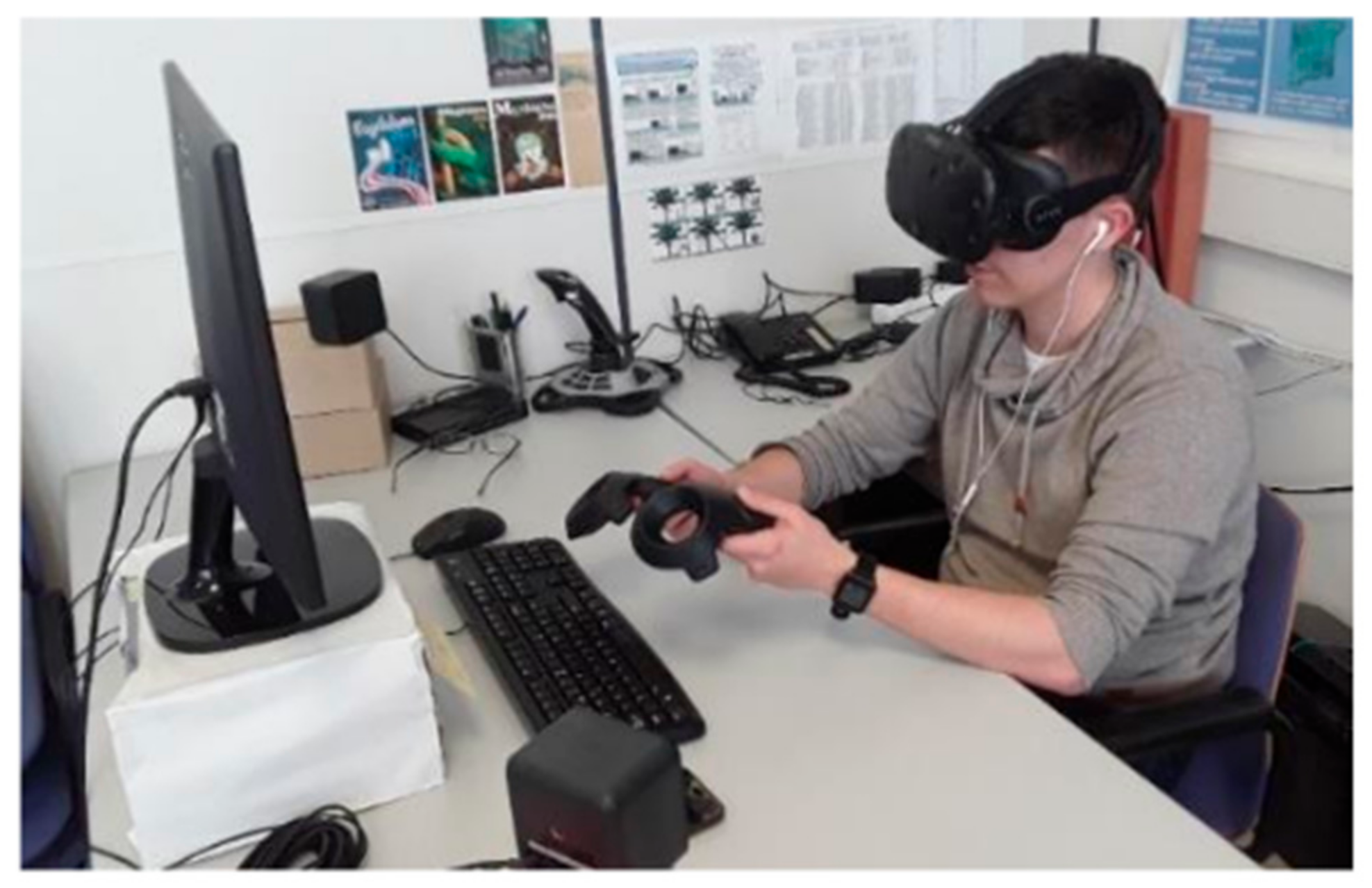
The current experimental setup can be observed in Figure 2, where the HTC Vive (https://www.htc.com/es/virtual-reality/) system creates a realistic 3D immersion in a friendly manner. Its main specifications are: 110 degrees field of view, 90 frames per second, 2160 × 1200 resolution, 32 sensors in the glasses for spatial localization, and 24 in each controller. It is recommended to use a graphics card higher than the 1060 range of NVidia. In our case, we used an NVidia 960GTX, with 8 GB of DDR3 RAM, and an Intel Core i7-4790 3.60 GHz.
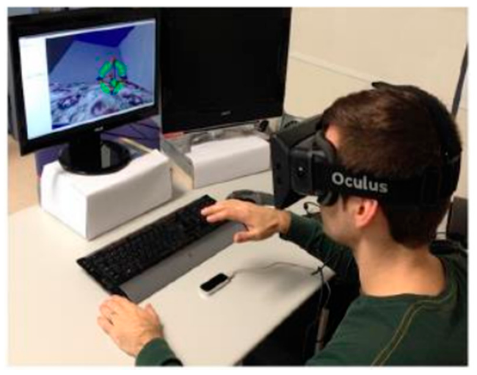
A question arises here: why are we using the HTC Vive system in place of the previous one [25] that included Oculus Rift and Leap Motion (LM, see Figure 3)? The main reason of discarding an LM device is the precision of the movements, which would be less than that of a joystick, for example. The second reason is that these devices are designed for the detection of hand movements and gestures, which could make learning to control the robot a bit difficult, due to the number of possible actions. These actions would have to be differentiated in a clear way to avoid serious errors. For a similar reason we have left aside the joystick, only one would be insufficient while two would require a long period of training Regarding the glasses, we decided to use the HTC because it includes its own controls (instead of joysticks). In fact, they have been demonstrated to be very useful during the experimentation task, taking into account the wide range of buttons and pads available. In addition, the communication between the controls and the computer is safe and not difficult to implement.
3.2. Unity (Game Engine) vs. UWSim
IRS-Lab has previous experience with VR environments. Using UWSim [6] Hardware in The Loop (HIL) simulator, we developed an HRI system, adapting hardware and software to the intended mission scenario. UWSIM has been shown to be a very useful tool in the simulation of ROS-based robotic systems, enabling the integration of simulation tools for networked robots (e.g., NS3). UWSIM offers a great open-source system that is very active and also has great applications in educational robotics. It is noticeable that UWSim has been shown to be a great tool for education, simplifying the interaction with the real G500 ROS-based robot control, as well as incorporating the possibility of configuring currents and water turbidity into the scene itself. Further, it includes a benchmarking module, which enables the results from different robot control algorithms to be registered and compared, in a web-based manner. At this point of time, we have not included any type of uncertainty from environment or sensors in the system.
But now the new challenge is to improve the immersive capacity (VR) 3D of the simulator. To implement the VR system from scratch in UWSim would take a long time, which would delay the usability tests and the project. An alternative is to use the Unity gaming engine, by Unity Technologies, [41]. Unity has integrated (as a plug-in) several drivers for different VR equipment. Further, Unity provides a more immersive experience, as well as facilities for the integration of VR devices.
An important point is that, eventually, we are going to use the interface presented here with real robots (further details in the Future Work section), which using UWSim will not allow without important modifications in the simulator.
Another critical point under consideration is the multibody interaction problem. In fact, the UWSim physics for modelling the simulation of multibody interaction, such as in the case of TWINBOT project, is not perfectly solved yet. Some solutions have been designed in UWSim for this (e.g., ObjectPicker), which are very interesting for fast prototyping, while the Unity 3D physics model (https://docs.unity3d.com/Manual/PhysicsSection.html) gives a more realistic response to this problem. Let’s not forget that UWSim presents a better integration with ROS than Unity, which is very interesting for current research and potential applications, such as education and so on.
Unity and UWSim represent two different tools for two distinct purposes. Moreover, the Unity platform enables, as will be seen in the following sections, the design of simulation servers that provide more realistic sensor inputs, especially in the case of water scenarios. Hence, our suggestion would be to select the best tool for each specific need.
4. Results
4.1. Suitability of HTC Glasses for Immersive VR 3D
We created a functional simulation from which performance and accuracy data of the VR interface could be extracted, and we did some tests to identify the performance of the graphics cards used. Let us keep in mind that the response time of these cards will be key to properly process the orders sent through the controls of the glasses used (HTC Vive). It is noticeable that the possibility of applying VR environments to the control of underwater robots is dependent of a suitable graphic card performance, among other factors. Thus, some specific tests were implemented to discover how they perform (i.e., response time) when the user gives orders through the controls of the HTC glasses (see Figure 4).
The results obtained using three different computers, using three distinct computational overload tests are shown in Figure 4. The test covers the following modes: (1) Stand by, which is representing the robot and the scenario rendering process without any robot movement, (2) Average overload, which moves the robot in an intermittent manner, and (3) High overload, which performs robot movements constantly (i.e., picking and dropping objects). All the computers had an Intel® Core™ i5-7300HQ 2.5 GHz and 8 Gb of DDR3 RAM memory except the one with a Geforce 820M that had 12 Gb of RAM memory. The worst results correspond to those of the GeForce 820M that is considered a graphic card for laptops. The best results have been obtained with the GeForce GTX 960 graphics card, where the performance was a 4-millisecond response time when working in Stand by mode 5 milliseconds in Average overload, and 10 milliseconds in High overload.
4.2. VR Functionalities
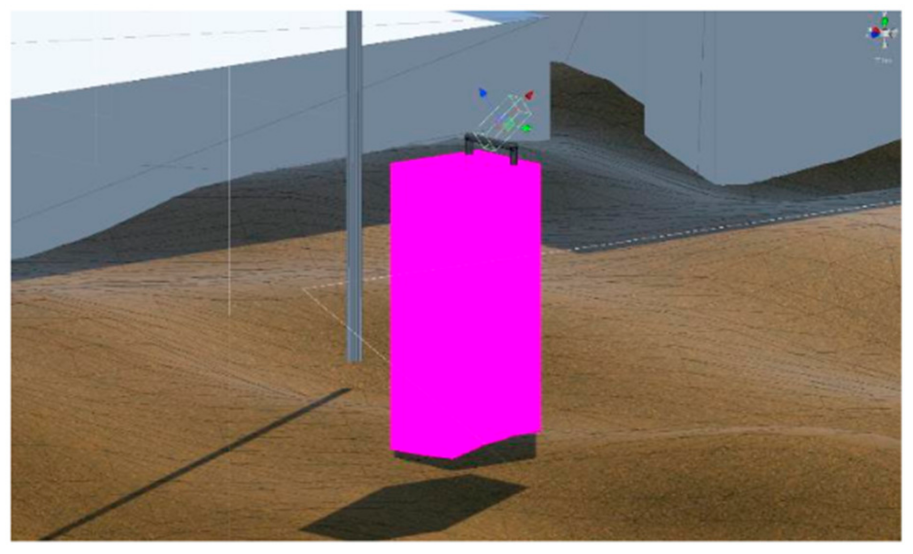
With the aim of improving the assistance to the user during the teleoperation process within an intervention mission, new VR functionalities have been implemented. In order to test this concept, a realistic scenario has been implemented dealing with recovering an aircraft’s black box from the bottom of the sea. Thus, a couple of images are displayed in Figure 5 and Figure 6, where the target (i.e., black box) intervention area is shown before and after being approached by the robotic gripper in charge of the recovery procedures.
Figure 5 shows the initial state of the intervention target, with the black box model included inside the simulation as a graspable object. All the simulated objects that can be manipulated by the robots have been tagged as Takeable within the Unity editor. In fact, this functionality is supported by a communication process between several classes, which activates and deactivates the highlighters of the objects, giving a special color to the targets when they can be picked up by the gripper (see Figure 6). Images of a real sequence can be seen in Figure 7. The complete grasping sequence of actions (i.e., approach, grasp and recovery of a black box) can be observed in this video in the Supplementary Materials section.
This new VR functionality is helping the user to teleoperate a target, as it is a visual confirmation of the correct grasping position of the arm and the robot.
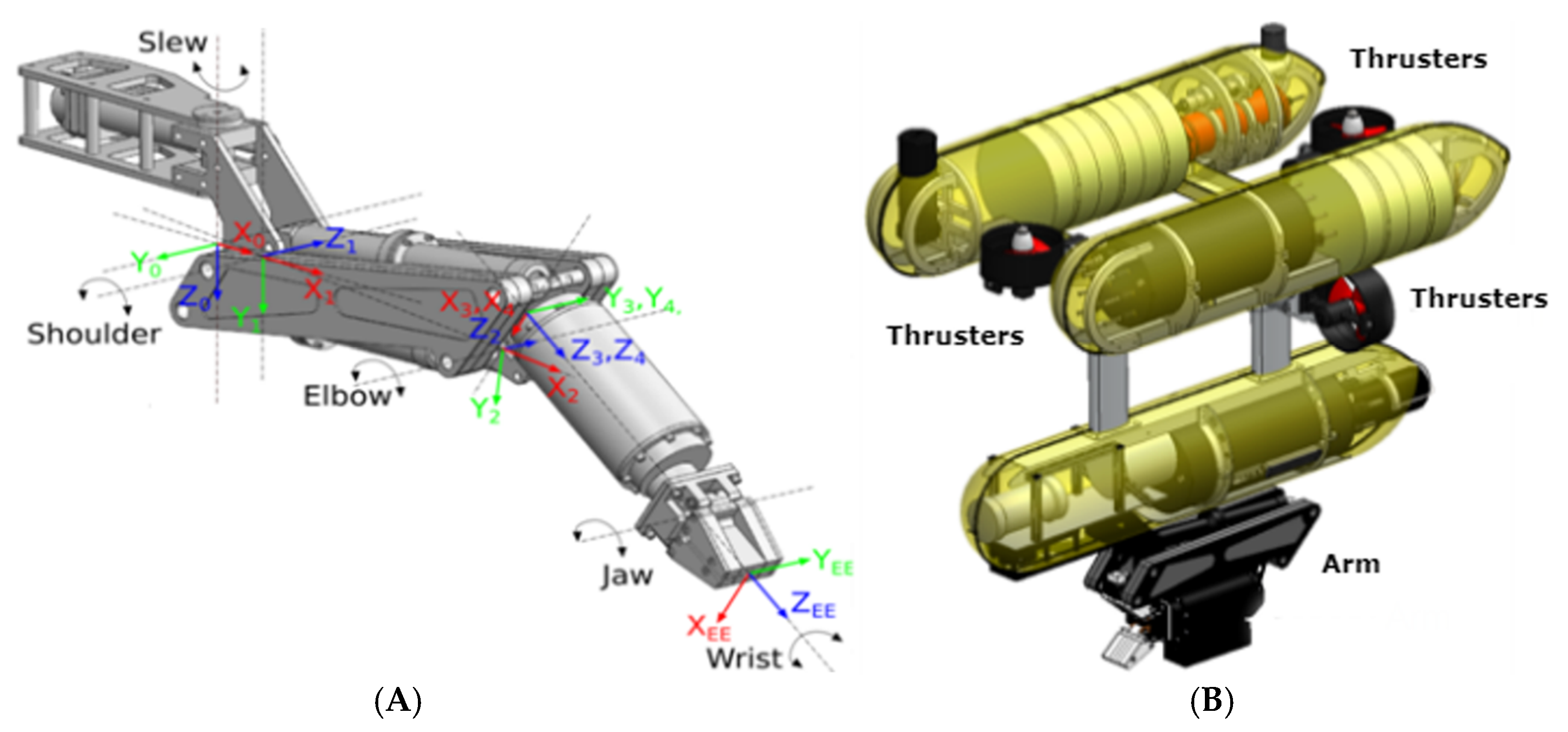
The submarine robot simulated is a Girona500 (https://cirs.udg.edu/auvs-technology/auvs/girona-500-auv/), the one used in the TWINBOT project, and the arm, an arm5e [42]. They can be seen in detail in Figure 8 (A, the robot and B, the arm).
4.3. VR Interface
The VR interface can be divided in two parts: control of the robots and visual information feedback.
In the first public version of the VR interface (after some internal testing and modifications), the controls have been divided into two groups; those in charge of managing the vehicle and those in charge of managing the arm.
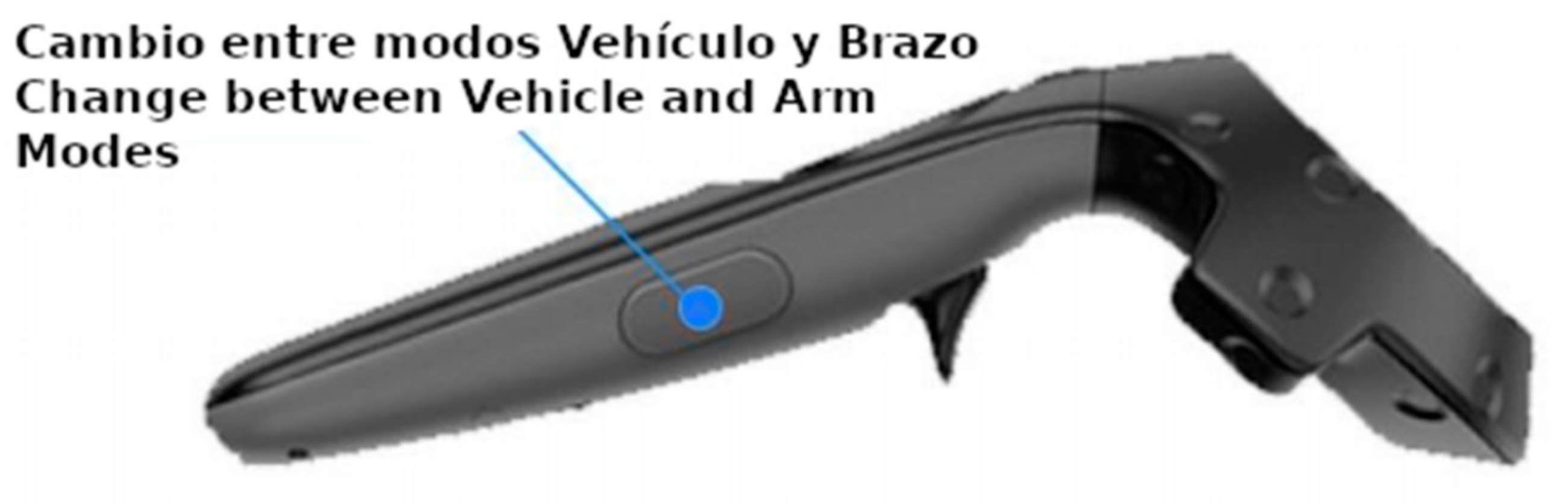
In the first version there are two independent modes which the user can select with the side button of the controller (Figure 9), this will also change the camera view from the vehicle to the arm.
In the second version of the VR interface, there is a third mode, which allows the user to see through the vehicle camera in order to control the arm. This work method is helped by the change of location of the vehicle camera, which is now not in the middle of the vehicle, but at its bottom.
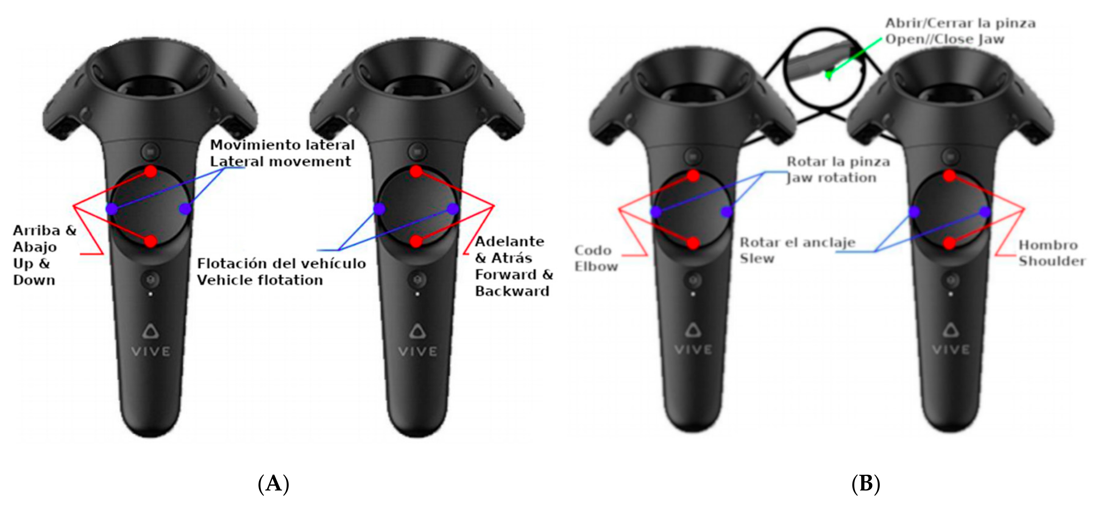
When selected, the right hand controller manages the forward and backward movement and the rotation of the vehicle, while the left one controls the up, down and lateral movements (Figure 10A).
In the arm mode, the right hand controller will manage the upper part of the arm (shoulder and slew) and the left one will control the lower part (elbow and jaw). Both of them have a trigger that will control opening and closing the griper (Figure 10B).
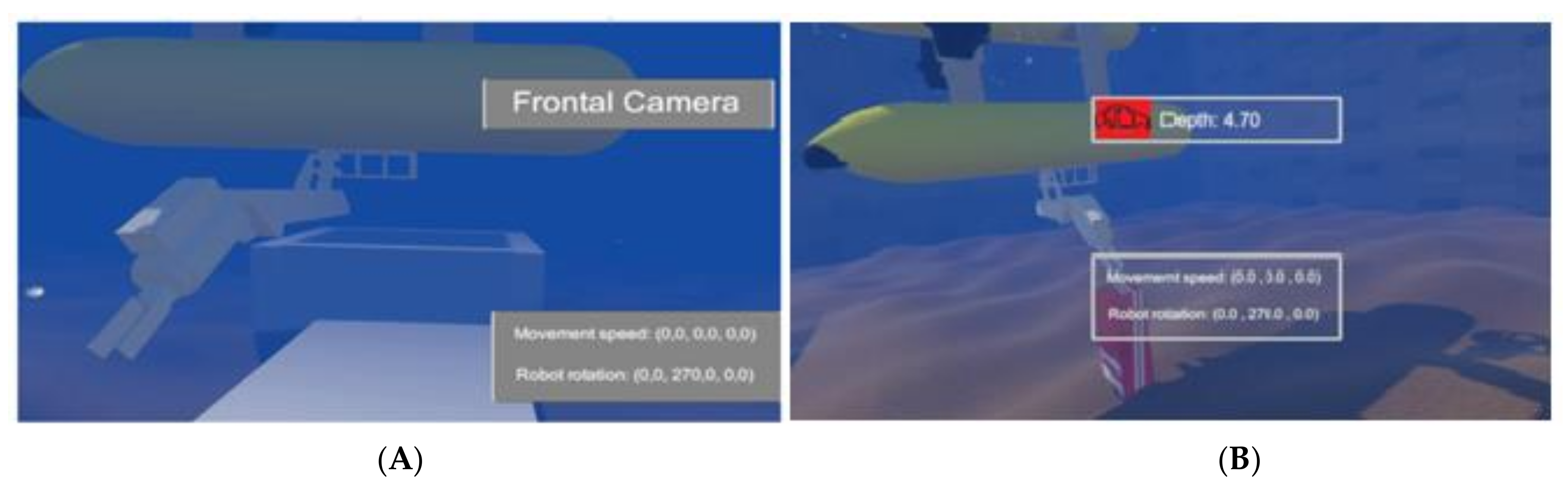
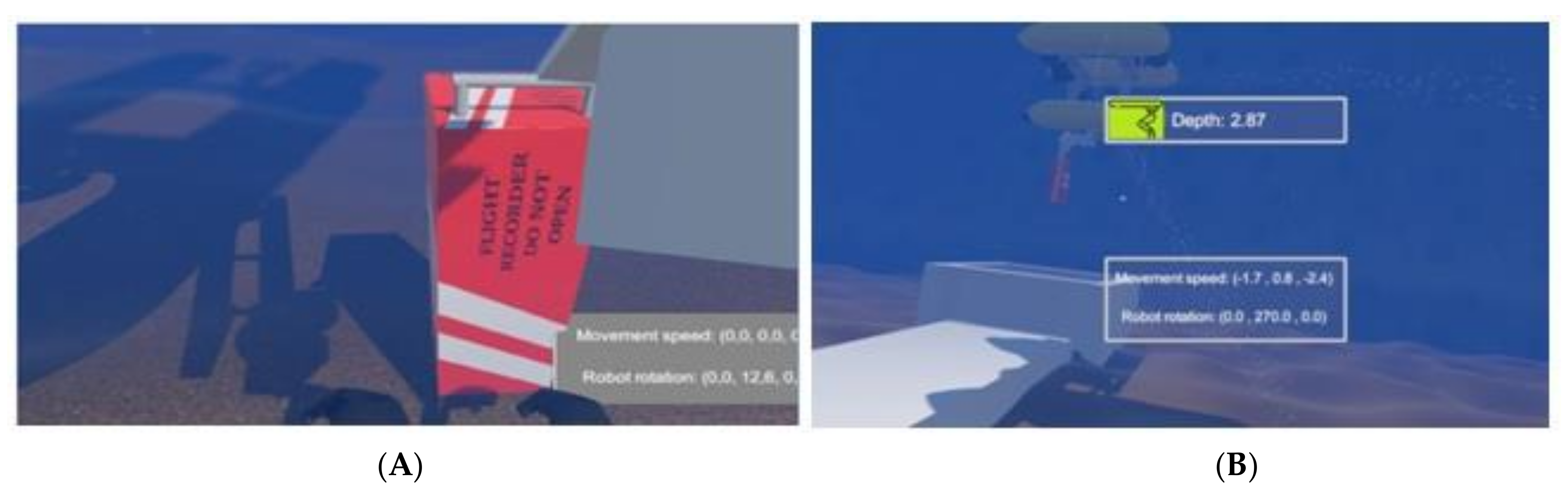
On the screen, using floating view-field windows (or display-fixed in [43]) the active camera image is shown (robot and arm), as well as some extra information for the operator. In the First version (Figure 11A) the solid view-field windows were placed near the limits of the user’s field of vision. In order to make them easier to see and interpret by the user, we moved them to the center of the screen and made them transparent, so that the active camera image is better appreciated (Figure 11, Figure 12, Figure 13 and Figure 14, B).
The view-field windows are divided into two sections (up and down in the screen):
- The movement section, which shows information about the vehicle movement speed and rotation in the first version.
Initially, there was a third section, the FPS and Input Lag, in which the information of images per second and delay between time of sending and processing of the signal was shown. In later versions, this information is not shown to the user, but is shown on the computer monitor.
The visual information feedback also includes a change in color in the black box when the submarine robot is near enough to grasp it (Figure 4 and Figure 5).
In Table 3, we can see the differences between the first and second versions of the VR interface.
4.4. Usability Tests
The usability of the VR interface developed was tested on four different environments with different difficulty levels. From lesser to greater difficulty they were:
- In the first test the camera is in third person and the user needs to take the black box and bring it to the white container (in Figure 11). The user only knew about the camera change button and that the elements moved with the touchpad.
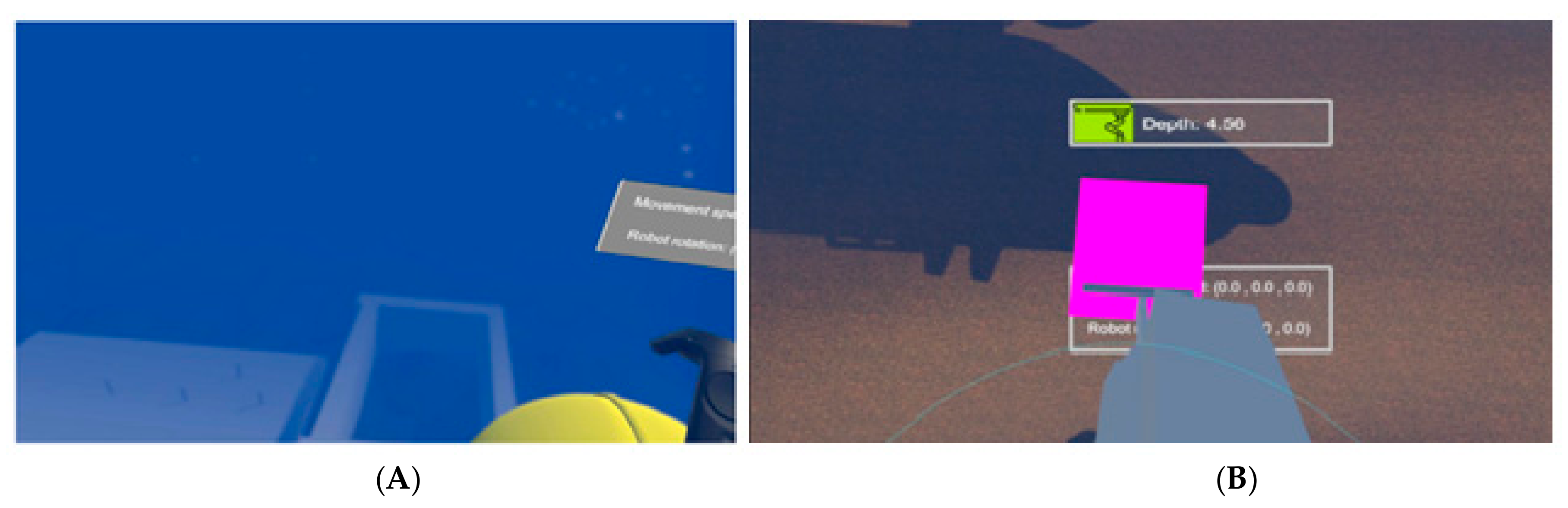
- In the second test the problem to solve is the same but the camera is on the arm of the robot (in Figure 12).
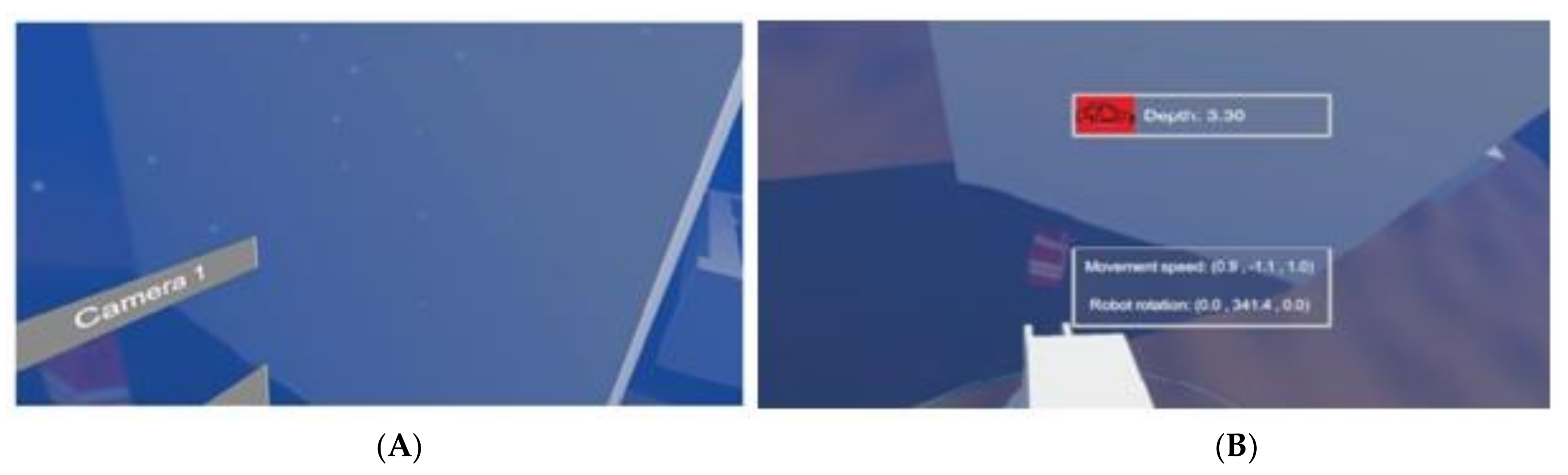
- In the third test, the camera is placed on the body of the robot (in Figure 13).
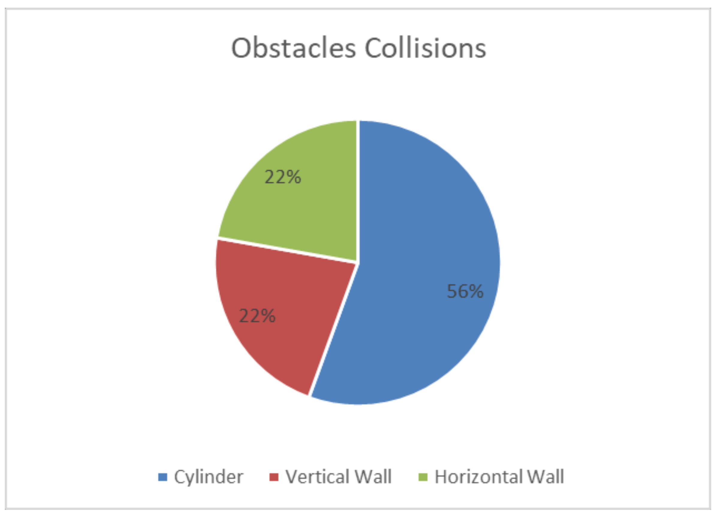
- In the last test, there is an obstacle between the black box and the robot (Figure 14). This obstacle can be a Cylinder, a Horizontal Wall or a Vertical Wall, adding a random factor.
As one of our aims was testing how easy and natural it was to learn how to use the interface, the users had minimal (verbal) information about the robot and the arm. The first test, with their cameras (points of view) positioned outside and independent of the robot, was considered sufficient to allow them to create a mental model of the vehicle.
The first VR interface was tested with a user group of 25 members, which were a heterogeneous group of students, researchers and teachers of computer science and video games. Before their trials with the interface, they were asked about their experience with VR and video games to generate a value (0–1) which indicated his affinity towards the test.
The characteristics of the users, the number of attempts and the time they took in each of the tests for the First version of the VR interface is shown in Table 4.
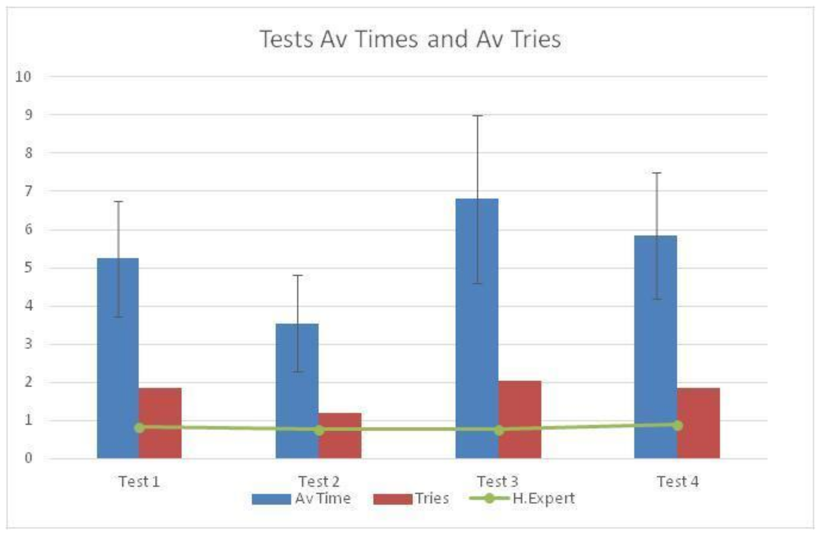
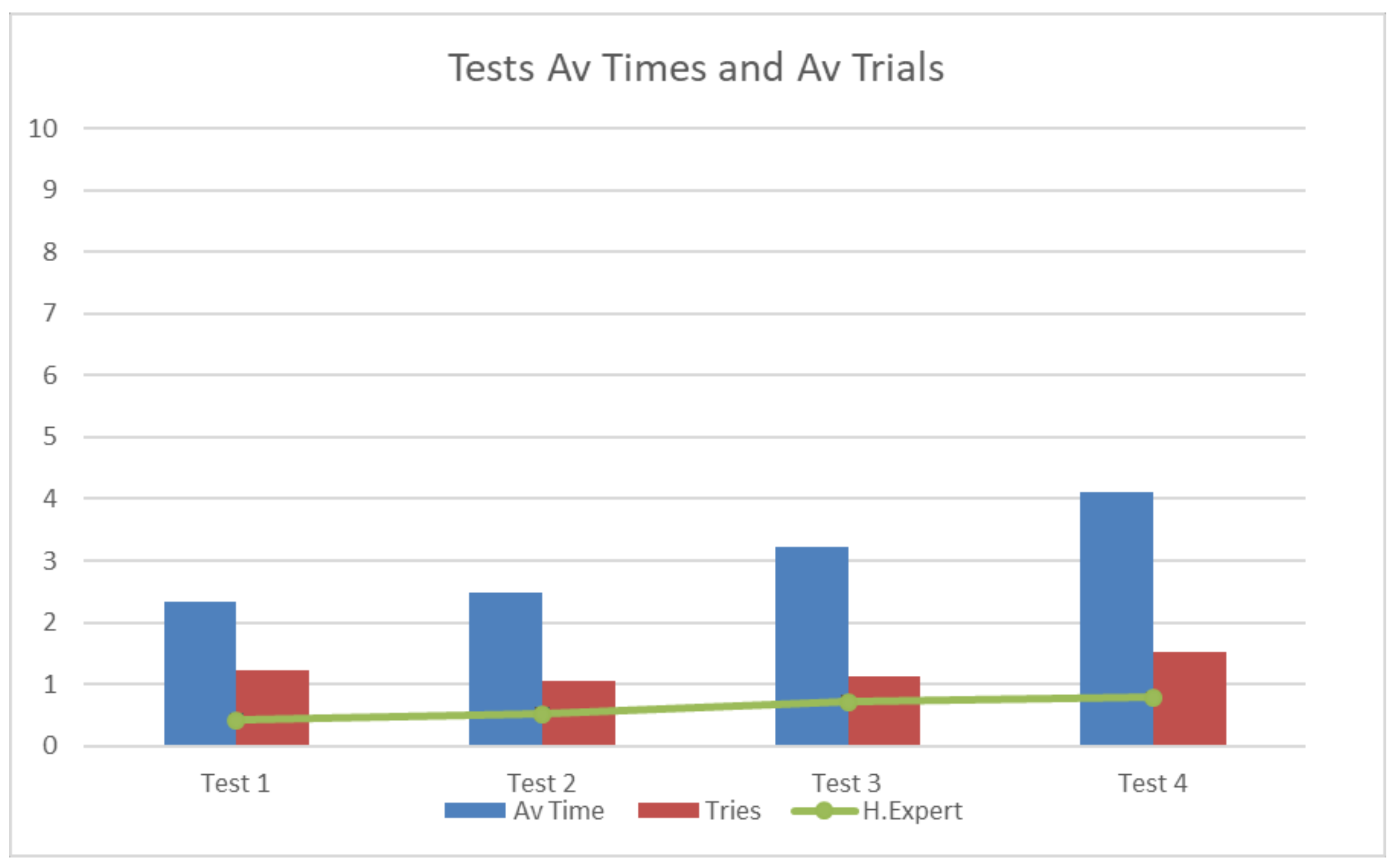
The average time for each task can be seen in Figure 15 and as expected shows a clear relationship between number of trials and time taken to complete the tasks: more time is associated with more trials needed to complete successfully a task.
At the end of the tests the users did a small questionnaire inspired by SUS:
- Are the controls easy to learn?
- Is the environment realistic?
- Do you think that the interface is really useful?
- Would you add something to the interface?
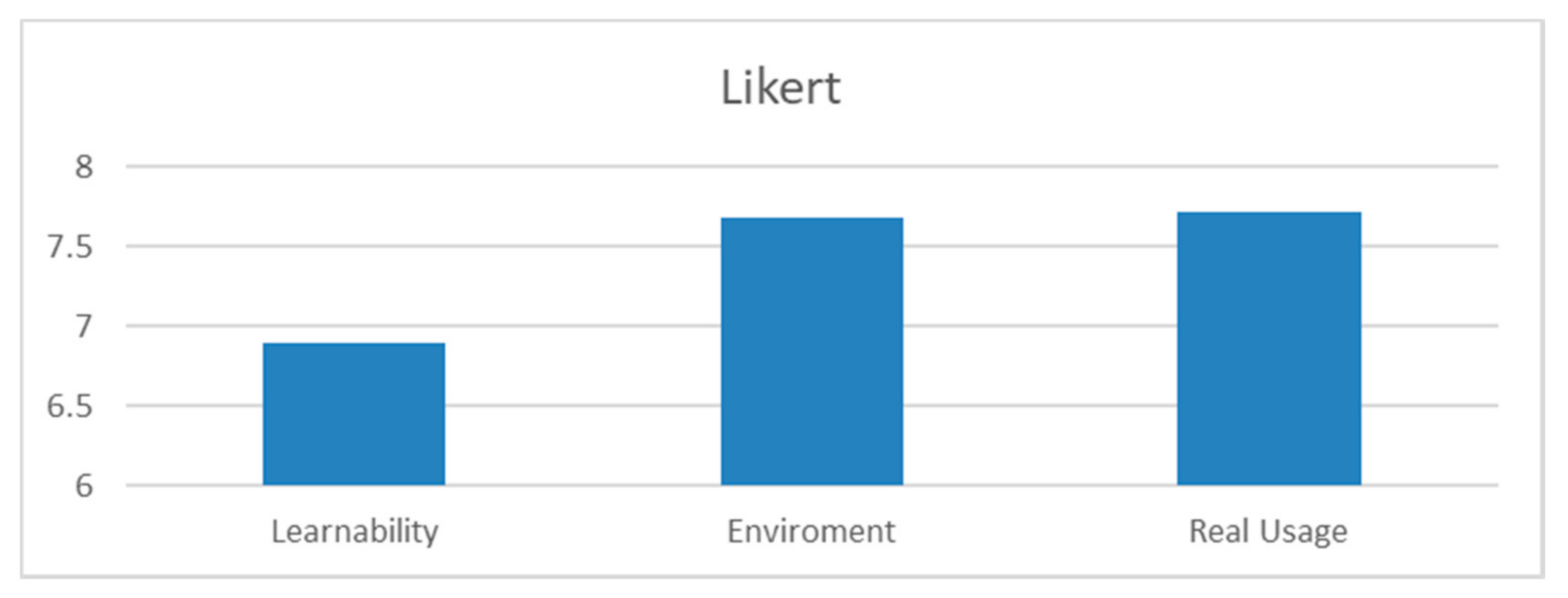
The answers provided us with information about their feelings in relation to the simulation. Their opinions were diverse but all considered that a tutorial would simplify the learning. In Figure 16, we can see a summary of their expressed satisfaction with the system.
Figure 16 shows how easily the users think that they were able to learn all the controls in the simulation and make good use of them, how realistic the environment was for them and if the simulation can, in their opinion, be useful in a real intervention.
For the learning time a score of 6.9 out of 10 was obtained. Taking into account that the basis of the test was that the users had no information and that they had to discover the function of the controls as they used them, resulted in a higher mark than expected in the first instance.
As for the environment, the mark was a 7.86 out of 10. The most significant comment is that we could try to simulate water streams with enough force to hinder the handling of the robot, which would be interesting in a future extension of the project, but in general the evaluation given was excellent and again beyond our expectations.
Finally, the user was asked about the real usefulness that they believed the interface would have in a real intervention and they gave a score of 7.72 out of 10, giving comments such as, “if used as a training tool, it might be a good idea to try to adjust the 1Hz refresh rate to simulate a wireless intervention, and some more information such as depth could be added to the information shown in the glasses ”. This will be taken into consideration in the new versions of the system.
Some of the users said it was difficult for them to imagine the robot, specifically the robot arm, which made it more difficult to control. They declared that watching the robot from the exterior in the two first tests was not enough to get a good mental model of the robot and the arm. This is supported by the type of collisions, as the Cylinder, a supposedly easier obstacle (smaller), caused more collisions than the bigger and more visible ones, the walls (rates in Figure 17). Aiming to solve this problem, we created a simple explanatory document about the robot, the arm and the controls, in the form of a short manual (the link can be found in the Supplementary Materials section) for the second version of the system, to complement the oral explanations that were given in the first version. A series of VR videos moving cameras around the robot to clarify its form were also created (The links are https://youtu.be/sLfUisdYlzM, https://youtu.be/LwgQM54GhM0, https://youtu.be/Fzp7_ud9NXA and https://youtu.be/heeDfSPIOzg).
The Second version of the VR interface was also tested with a heterogeneous group of users (their characteristics can be seen in Table 5, some of them participated in the previous tests).
The average time for each task can be seen in Figure 18 and again they show a clear relationship between number of trials and time taken to complete the tasks: more time is associated with more trials to successfully complete a task.
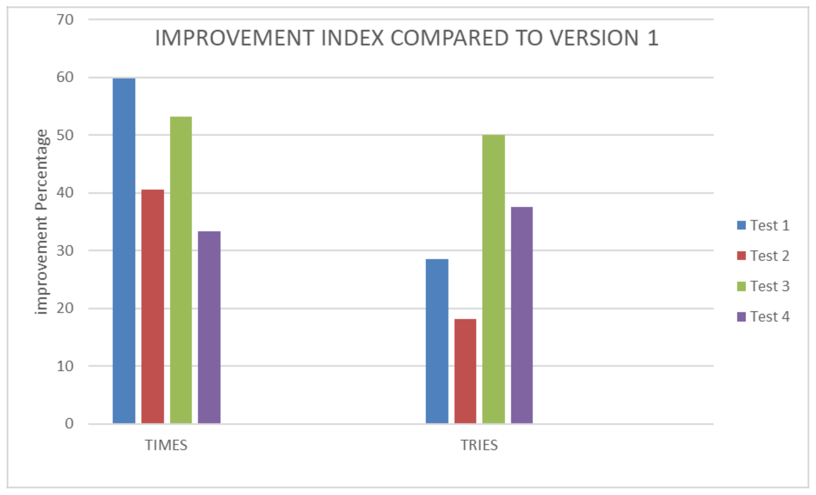
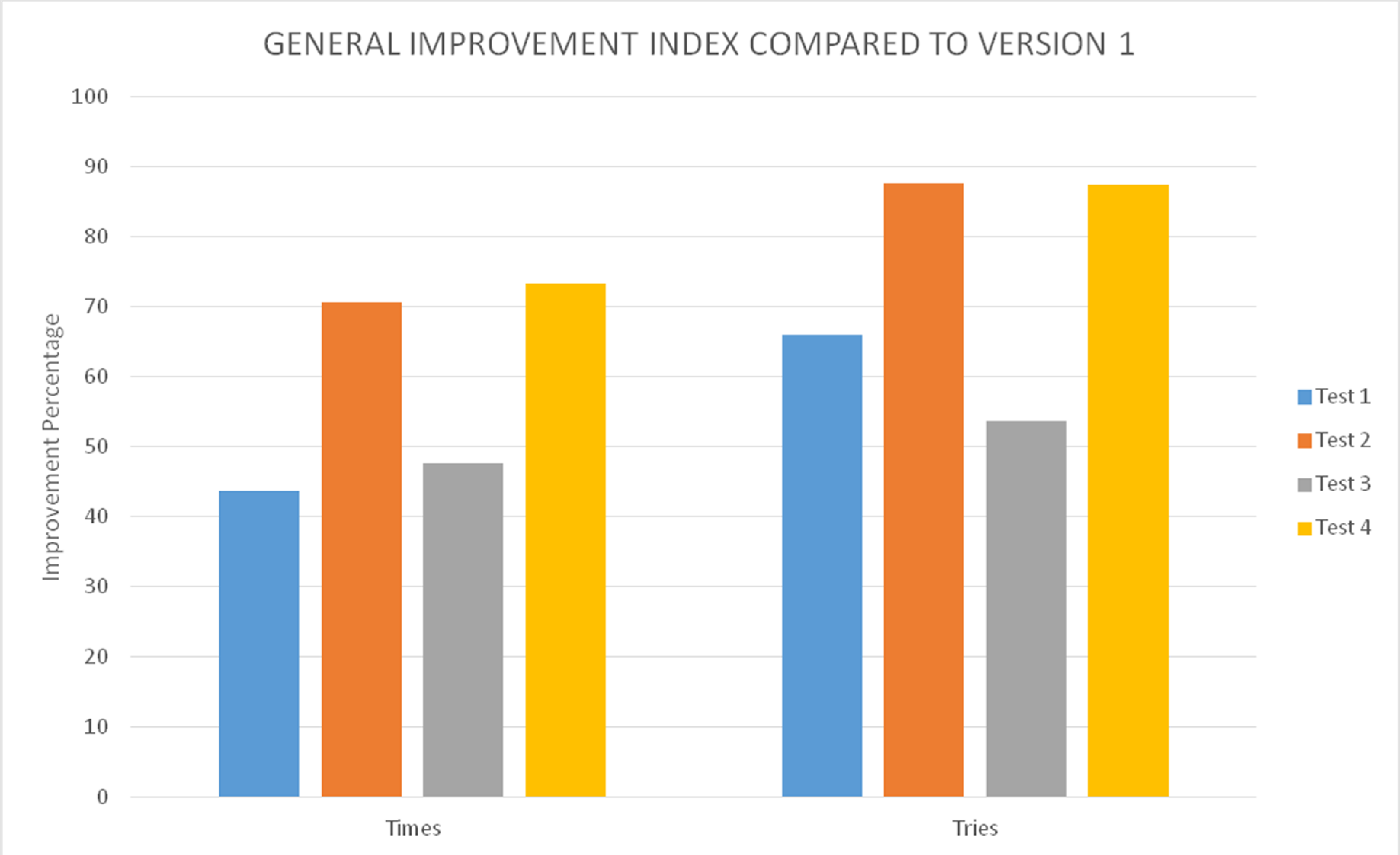
If we compare Figure 15 (First version) and Figure 18 (Second version), we can see a clear improvement. When we compare the repeated users results (as can be seen in Figure 19), we can clearly see that both time and trials decreased from one version to the other.
There was a clear improvement between versions when we compare the repeated users results (as can be seen in Figure 20), as time and trials decreased.
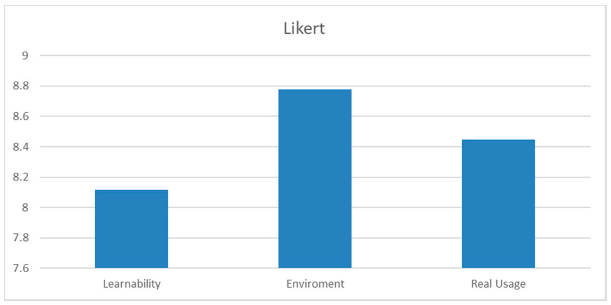
The same questionnaire was filled in by the users and the results can be seen in Figure 21 with better results: Learnability 8.12, Environment 8.78 and Real Usage 8.45. Some comments were different: although they found the sounds useful, some of them did not like the increase in frequency of the one that indicated a collision. One user suggested that we could create a virtual avatar of the user, putting him/her in a virtual cabin that would be attached to the vehicle.
The collision problems have changed, as can be seen in Figure 22 which shows the type of collisions in rates, as the Horizontal Wall has disappeared while the Cylinder continues to cause more collisions than the bigger and more evident ones. The biggest improvement was due to the collision warning sound, as expressed by the users.
4.5. Efficiency
According to ISO-9241 (https://www.iso.org/standard/77520.html) Ergonomics of human-system interaction, product Efficiency can be defined as “resources expended by the user in order to ensure accurate and complete achievement of the goals”.
With regards to software products and information systems, the key measured resource normally is time spent by the user in order to achieve the goals.
Thus, Efficiency can be calculated as user Effectiveness divided by the time spent by the user.
Let N—be the total number of scenarios/goals (4 in our case)
R—is the number of respondents/users (25 in the First version, 17 in the Second one in our case)
nij—is the result of coming through scenario i by user j; nij = 1 if the task has been completed successfully and user goal has been achieved, and nij = 0, if the task is unfinished and user failed to achieve the goal (all our users completed the task eventually).
tij—is the time spent by respondent j to come through scenario i. In case of unsuccessful scenario completion, measured till the moment the scenario is left by the respondent as a result of giving up trying to reach the goal or logging off the system.
Then, overall time-based user Efficiency of a product Pt will be calculated according to the following Formula (1) in which a perfect Efficiency (all tests finished successfully in one second, the time unit used) should be 1 and 0 if no user was able to finish any task:
The Efficiency of the First VR system is thus 0.004131 and 0.007697 in the Second VR one.
If we use the time spent by some of the users in their first (and unsuccessful) try of the different tasks, the time-based user Efficiency was different: 0.003642 for the First version and 0.006470 for the Second one, clearly worse.
We can calculate overall relative time-based Efficiency using Formula (2):
In the First version we obtained a 69.74% (taking into account the last try of each user we will have obtained a 100%, which does not provide us with useful information) and 91.82% for the Second.
The person who was the main creator of the simulation and interface, acted as our expert to calculate Expert Efficiency. He was able to come through tasks with the maximum possible user speed and an a-priory successful completion.
Let t0i—be the ideal time an expert needs to complete scenario i.
Then, the time-based expert Efficiency will be (3):
The physical meaning of the time-based expert Efficiency is the highest theoretically possible speed of work with the product. The value obtained was 0.0203 in version one and 0.0292 in version two.
These results clearly prove that the Second VR interface is better than the First one.
4.6. Comparison with Previous Work
It was fortunate that some (three) of the users had been also part of the usability study presented in [25], we interviewed them in depth, with interesting results:
Subject 1 clearly prefers HTC Vive, as he/she felt dizzy when using the Oculus technology. He/she had to restart the test several times before completing because he/she felt sick, a common problem when using VR (more details on cybersickness can be found in [44] and [45] among others).
This sickness did not appear in the Second version of the VR interface.
Subject 2 considers that while the HTC Vive system is nicer, the Oculus one is easier to use because it provided more information. He/she did prefer the joystick and he/she didn’t see the need to have two different control instruments (they couldn’t be used at the same time and learning to use them was challenging). Changing the point of view was a problem for this user. After testing the Second version he/she still would have preferred a joystick but he was happier with the controls.
Subject 3 preferred the Oculus system as he/she considered the quality of the simulator (UWSim) to be better. He/she did not have problems using the joystick to control the robot and felt that using two hands was unnecessary. He considered that maybe it could be useful in more complex tasks. He agreed with other users that the Second VR interface was an improvement compared to the First, but he still preferred the UWSim as a simulator.
Some users participated in the tests of the First and Second VR interface. All of them expressed a clear preference for the Second version.
4.7. The Training and Integration Server
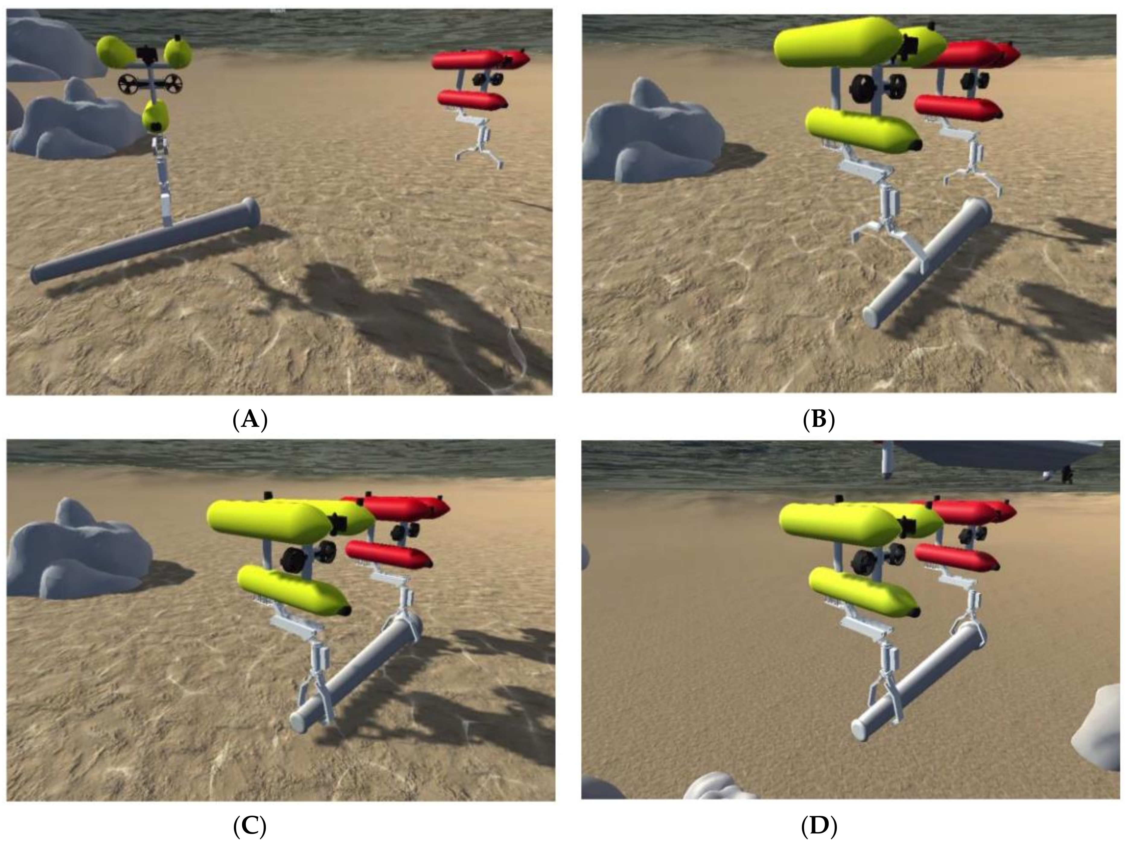
Finally, as can be observed in Figure 23, a training and integration server is under development. It will integrate all the hardware and software for the complete TWINBOT scenario. This complex VR 3D scenario includes two I-AUVs (Girona-500), with the arms, cameras and all kinds of sensors within a harbor context or similar. Implementation details are out of the scope of this paper because they are linked with the global TWINBOT project, but in Figure 24 can be observed a task sequence.
The simulation server accepts network commands in several formats, such as TCP/IP and HTTP, providing the sensor information (e.g., robot positions and camera images) in http/JPEG and JSON packets respectively, while a ROS interface is under development.
Examples of the TWINBOT Simulation Server (TSS) state during an interaction with the GUI are shown in Figure 17.
5. Discussion and Future Work
We have seen how an immersive VR interface to a simulated underwater vehicle has been created and tested, as part of the TWINBOT project. As expected, it has shown that users prefer this type of interface to others which are harder to learn and use. Finally, some videos are linked, in the paper, in order to make it easier to understand the system in action.
Thanks to the usability tests, some ideas have been taken into consideration, such as the inclusion of some extra data in the information that is shown to the user in the glasses, information like the actual vehicle depth, the pressure and the forces applied to the ROV. The development of the interface has not ended.
The users also suggested making the simulation more realistic, not simply with better graphics, but changing the refresh rate of the simulation to 1 Hz in order to represent the problems of a real wireless connection with the robot. Let us not forget that nowadays we are not able to send full high definition pictures at a rate of 60 Hz.
Another point to take into account is that, as previously noted, the system does not include any type of uncertainty from environment and model. A realistic simulation requires some degree of uncertainty and we would include it in the future.
It should be noted that the subjectivity problem is unavoidable when working with human beings but in our case it is reduced by the number of users of the study. At the same time, the time and trials employed in the different tests are a good indication of the real usability of the interface.
In the future, there are several important developments we have to complete in order to finish the HRI:
- Integrate another robot into the simulation (later to be a real robot), with the aim that they cooperate in solving problems with the user controlling only one of them at a given time. Although a priori it would be interesting to have an interface able to allow two or more users guiding their own robots, previous experiences have shown how the umbilical cables knot themselves in this case. In the latest version of the simulator we have already included two robots but we have yet to incorporate a mechanism integrated into the interface that will allow the operator to switch control from one to the other. As the simulation becomes more complex, it can become necessary to create a master-slave model to define the relationship between the robots and the human user.
- Connect the interface to a server simulator (discussed in Section 4.7) as a first step towards making a connection with a real robot. We plan to develop a connection layer [3] between the real robot and the simulator. In order to do so, it will be necessary to transform the signals for the buttons (which are detected in C#) to movement signals for the robot which has an ROS system.
- Transform our VR interface into an AR one, with information provided by the robot sensors (simulated or real).
- To further develop the learning process we plan to improve the interface manual and the VR videos to make it easier to understand the hardware. A more complex sequence of problems is being developed, and there are plans to use it in a master degree in underwater robotics (http://www.master-mir.eu/?trk=public-post_share-update_update-text).
- As use of a VR system can cause fatigue problems when used for long time periods [46], we would like to explore techniques and design concepts that help to reduce fatigue.
Of course they are not the only possibilities for future developments. It would be interesting to increase the dimension of the project by adding artificial intelligence to reduce the need for user intervention, as some “hybrid” systems already do [12].
Another interesting possibility is integrating different tools to interact with the simulation, which could help the users to control the robot [25]. For example, using the microphone incorporated in the HTC Vive, which could allow the user to change the point of view by voice commands and this could increase the usability of the interface and reduce the learning curve.
Supplementary Materials
In this video we can see the simulation with the underwater robot controlled by a human user using the VR interface, it is available online at https://0-www-mdpi-com.brum.beds.ac.uk/2218-6581/9/4/81/s1. The following are available online at https://drive.google.com/file/d/1HEWAS3iRfuBrlSckTAr6heunLGHObPLq/view?usp=sharing, Video S1: complete grasping sequence of actions. At https://drive.google.com/open?id=1upnAiUqe72CikbOLRm4tuISfQWTsXazs, an interface manual. And at https://youtu.be/sLfUisdYlzM, https://youtu.be/LwgQM54GhM0, https://youtu.be/Fzp7_ud9NXA and https://youtu.be/heeDfSPIOzg, several VR videos to make easier to understand the hardware.
Author Contributions
Conceptualization, M.d.l.C.; Formal analysis, G.C.; Funding acquisition, P.S. and R.M.; Investigation, M.d.l.C.; Methodology, P.S. and R.M.; Project administration, P.S.; Software, M.d.l.C.; Supervision, P.S.; Writing—original draft, G.C. and P.S.; Writing—review & editing, G.C. and P.S. All authors have read and agreed to the published version of the manuscript.
Funding
This work has been partly funded by Spanish Ministry of Economy, Industry and Competitiveness under grant DPI2017-86372-C3-1-R (COMOMUIS Project), by Valencian Government under GVA-PROMETEO/2016/066 grant, under FEDER project IDIFEDER/2018/013 and by UJI under UJI-B2018-34 grant (NEPTUNO Project).
Conflicts of Interest
The authors declare no conflict of interest. The funders had no role in the design of the study; in the collection, analyses, or interpretation of data; in the writing of the manuscript, or in the decision to publish the results.
References
- Lin, Q.; Kuo, C. On Applying Virtual Reality to Underwater Robot Tele-Operation and Pilot Training. Int. J. Virtual Real. 2001, 5, 71–91. [Google Scholar] [CrossRef]
- Ridao, P.; Carreras, M.; Ribas, D.; Sanz, P.J.; Oliver, G. Intervention AUVs: The next challenge. Annu. Rev. Control. 2015, 40, 227–241. [Google Scholar] [CrossRef] [Green Version]
- Yuh, J.; Choi, S.K.; Ikehara, C.; Kim, G.H.; Me Murty, G.; Ghasemi-Nejhad, M.; Sarlear, N.; Sugihara, K. Design of a semi-autonomous underwater vehicle for intervention missions (SAUVIM). In Proceedings of the 1998 International Symposium on Underwater Technology, Tokyo, Japan, 15–17 April 1998; IEEE Press: Hoboken, NJ, USA, 1998; pp. 63–68. [Google Scholar]
- Sanz, P.J.; Ridao, P.; Oliver, G.; Melchiorri, C.; Casalino, G.; Silvestre, C.; Petillot, Y.; Turetta, A. TRIDENT: A Framework for Autonomous Underwater Intervention Missions with Dexterous Manipulation Capabilities. IFAC Proc. Vol. 2010, 43, 187–192. [Google Scholar] [CrossRef]
- Khatib, O.; Yeh, X.; Brantner, G.; Soe, B.; Kim, B.; Ganguly, S.; Stuart, H.; Wang, S.; Cutkosky, M.; Edsinger, A.; et al. Ocean One: A Robotic Avatar for Oceanic Discovery. IEEE Robot. Autom. Mag. 2016, 23, 20–29. [Google Scholar] [CrossRef]
- Prats, M.; Perez, J.; Fernandez, J.J.; Sanz, P.J. An open source tool for simulation and supervision of underwater intervention missions. In Proceedings of the IEEE/RSJ International Conference on Intelligent Robots and Systems (IROS) 2012, Algarve, Portugal, 7–12 October 2012; Curran Associates, Inc.: Red Hook, NY, USA, 2012; pp. 2577–2582. [Google Scholar]
- Miller, G. The magical number seven, plus or minus two: Some limits on our capabilities for processing information. Psychol. Rev. 1956, 63, 81–97. [Google Scholar] [CrossRef] [Green Version]
- Sanz, P.J.; de la Cruz, M.; Lunghi, G.; Veiga, C.; Marín, R.; Di Castro, M. The Role of HRI within COMOMUIS Research Project. In Proceedings of the Jornadas Nacionales de Robótica, Alicante, Spain, 13–14 June 2019; Fernando, T.M., Óscar, R.G., Eds.; Universidad de Alicante: Alicante, Spain, 2019; pp. 141–147. [Google Scholar]
- Preece, J.; Rogers, Y.; Sharp, H.; Benyon, D.; Holland, S.; Carey, T. Human-Computer Interaction; Addison-Wesley Longman Ltd.: Essex, UK, 1994; ISBN 0201627698. [Google Scholar]
- Sheridan, T.B.; Verplank, W.L. Human and Computer Control of Undersea Teleoperators; Technical Report; Massachusetts Inst of Tech Man-Machine Systems Lab: Cambridge, MA, USA, 1978; Available online: https://apps.dtic.mil/dtic/tr/fulltext/u2/a057655.pdf (accessed on 3 May 2019).
- Peshkova, E.; Hitz, M.; Kaufmann, B. Survey on Natural Interaction Techniques for an Unmanned Aerial Vehicle System. IEEE Pervasive Comput. 2017, 16, 34–42. [Google Scholar] [CrossRef]
- Chen, J.Y.C.; Haas, E.C.; Barnes, M.J. Human Performance Issues and User Interface Design for Teleoperated Robots. IEEE Trans. Syst. Man Cybern. Part C Appl. Rev. 2007, 37, 1231–1245. [Google Scholar] [CrossRef]
- Dicianno, B.E.; Sibenaller, S.; Kimmich, C.; Cooper, R.A.; Pyo, J. Joystick Use for Virtual Power Wheelchair Driving in Individuals with Tremor: Pilot Study. J. Rehabil. Res. Dev. 2009, 46, 269–275. [Google Scholar] [CrossRef]
- Huang, C.M.; Mutlu, B. Anticipatory robot control for efficient human–robot collaboration. In Proceedings of the 2016 11th ACM/IEEE International Conference on Human–robot Interaction (HRI), Christchurch, New Zealand, 7–10 March 2016; IEEE Press: Hoboken, NJ, USA, 2016; pp. 7–10. [Google Scholar]
- Shim, H.; Jun, B.; Lee, P.; Baek, H.; Lee, J. Workspace control system of underwater tele-operated manipulators on an ROV. Ocean Eng. 2010, 37, 1036–1047. [Google Scholar] [CrossRef]
- Sutherland, I.E. The ultimate display. In Proceedings of the International Federation of Information Processing IFIPS Congress, New York, NY, USA, 24–29 May 1965; Volume 2, pp. 506–508. [Google Scholar]
- Rheingold, H. Virtual Reality; Summit Books: New York, NY, USA, 1991. [Google Scholar]
- Chin, C.; Lin, W.; Lin, J. Experimental validation of open-frame ROV model for virtual reality simulation and control. J. Mar. Sci. Technol. 2018, 23, 267–287. [Google Scholar] [CrossRef] [Green Version]
- Anthes, C.; García Hernandez, R.; Wiedemann, M.; Kranzlmüller, D. State of the Art of Virtual Reality Technologies. In Proceedings of the IEEE Aerospace Conference, Big Sky, MT, USA, 5–12 March 2016. [Google Scholar] [CrossRef]
- Burdea, G.; Coiffet, P. Virtual Reality Technology. Presence 2003, 12, 663–664. [Google Scholar] [CrossRef]
- Bowman, D.; North, C.; Chen, J.; Polys, N.; Pyla, P.; Yilmaz, U. Information–rich virtual environments: Theory, tools, and research agenda. In Proceedings of the VRST ‘03 ACM Symposium on Virtual Reality Software and Technology, Osaka, Japan, 1–3 October 2003; pp. 81–90. [Google Scholar] [CrossRef]
- Sherman, W.; Craig, A. Understanding Virtual Reality—Interface, Application, and Design; Elsewier Science: New York, NY, USA, 2003. [Google Scholar]
- Lin, M.C.; Otaduy, M.A.; Boulic, R. Virtual reality software and technology. IEEE Comput. Graph. Appl. 2008, 28, 18–19. [Google Scholar] [CrossRef] [PubMed]
- Kot, T.; Novak, P. Utilization of the Oculus Rift HMD in Mobile Robot Teleoperation. Appl. Mech. Mater. 2014, 555, 199–208. [Google Scholar] [CrossRef]
- García, J.C.; Patrão, B.; Almeida, L.; Pérez, J.; Menezes, P.; Dias, J.; Sanz, P.J. A Natural Interface for Remote Operation of Underwater Robots. IEEE Comput. Graph. 2015, 37, 34–43. [Google Scholar] [CrossRef] [Green Version]
- Kot, T.; Novak, P. Application of virtual reality in teleoperation of the military mobile robotic system TA-ROS. Int. J. Adv. Robot. Syst. 2018, 15, 1729881417751545. [Google Scholar] [CrossRef] [Green Version]
- Schiza, E.; Matsangidou, M.; Neokleous, K.; Pattichis, C. Virtual Reality Applications for Neurological Disease: A Review. Front. Robot. AI 2019, 6, 100. [Google Scholar] [CrossRef] [Green Version]
- Rizzo, A.S.; Koenig, S.T. Is clinical virtual reality ready for primetime? Neuropsychology 2017, 31, 877–899. [Google Scholar] [CrossRef] [Green Version]
- Tan, Y.; Niu, C.; Zhang, J. Head-Mounted Display-Based Immersive Virtual Reality Marine-Engine Training System. IEEE Syst. Man Cybern. Mag. 2020, 6, 46–51. [Google Scholar] [CrossRef]
- Hsu, E.B.; Li, Y.; Bayram, J.D.; Levinson, D.; Yang, S.; Monahan, C. State of virtual reality based disaster preparedness and response training. PLoS Curr. 2013, 5. [Google Scholar] [CrossRef]
- Engelbrecht, H.; Lindeman, R.; Hoermann, S. A SWOT Analysis of the Field of Virtual Reality for Firefighter Training. Front. Robot. AI 2019, 6, 101. [Google Scholar] [CrossRef] [Green Version]
- Haydar, M.; Maidi, M.; Roussel, D.; Mallem, M.; Drap, P.; Bale, K.; Chapman, P. Virtual Exploration of Underwater Archaeological Sites: Visualization and Interaction in Mixed Reality Environments. In Proceedings of the 9th International Symposium on Virtual Reality, Archaeology and Intelligent Cultural Heritage, Braga, Portugal, 2–5 December 2008; Eurographics Ass: Geneva, Switzerland, 2008. [Google Scholar] [CrossRef]
- Bekele, M.; Champion, E. A Comparison of Immersive Realities and Interaction Methods: Cultural Learning in Virtual Heritage. Front. Robot. AI 2019, 6, 91. [Google Scholar] [CrossRef] [Green Version]
- Azuma, R.T. A Survey of Augmented Reality. Presence Teleoper. Virtual Environ. 1997, 6, 355–385. [Google Scholar] [CrossRef]
- Brantner, G.; Khatib, O. Controlling Ocean One. In Field and Service Robotics; Springer International Publishing: Cham, Switzerland, 2018; pp. 3–17. [Google Scholar] [CrossRef]
- Gancet, J.; Weiss, P.; Antonelli, G.; Folkert Pfingsthorn, M.; Calinon, S.; Turetta, A.; Walen, C.; Urbina, D.; Govindaraj, S.; Letier, P.; et al. Dexterous Undersea Interventions with Far Distance Onshore Supervision: The DexROV Project. IFAC-PapersOnLine 2016, 49, 414–419. [Google Scholar] [CrossRef]
- Abran, A.; Khelifi, A.; Suryn, W.; Seffah, A. Usability Meanings and Interpretations in ISO Standards. Softw. Qual. J. 2003, 11, 325–338. [Google Scholar] [CrossRef]
- Seffah, A.; Donyaee, M.; Kline, R.B.; Padda, H.K. Usability measurement and metrics: A consolidated model. Softw. Qual. J. 2006, 14, 159–178. [Google Scholar] [CrossRef]
- Brooke, J. SUS-A quick and dirty usability scale. In Usability Evaluation in Industry; Jordan, P.W., Thomas, B., McClelland, I.L., Weerdmeester, B., Eds.; Taylor & Francis, Milton Park: Abingdon-on-Thames, Oxfordshire, UK, 1996; pp. 189–194. [Google Scholar]
- Marsh, T. Evaluation of Virtual Reality Systems for Usability; Proceedings CHI 99, 15–20 May 1999; ACM: New York, NY, USA, 1999; pp. 61–62. [Google Scholar] [CrossRef]
- Unity User Manual. Available online: https://docs.unity3d.com/Manual/index.html (accessed on 3 March 2019).
- Fernández, J.J.; Prats, M.; Sanz, P.J.; García, J.C.; Marín, R.; Robinson, M.; Ribas, D.; Ridao, P. Grasping for the Seabed: Developing a New Underwater Robot Arm for Shallow-Water Intervention. IEEE Robot. Autom. Mag. 2013, 20, 121–130. [Google Scholar] [CrossRef]
- Feiner, S.; MacIntyre, B.; Haupt, M.; Solomon, E. Windows on the world: 2D windows for 3D augmented reality. In Proceedings of the 6th Annual ACM Symposium on User Interface Software and Technology, Atlanta, GA, USA, 3–8 December 1993; pp. 145–155. [Google Scholar] [CrossRef]
- McCauley, M.; Sharkey, T. Cybersickness: Perception of Self-motion in Virtual Environments. Teleoperators and Virtual Environments. Presence 1989, 3, 311–318. [Google Scholar]
- LaViola, J.J., Jr. A discussion of cybersickness in virtual environments. ACM SIGCHI Bull. 2000, 32, 47–56. [Google Scholar] [CrossRef]
- Lambooij, M.; Ijsselsteijn, W.; Fortuin, M.; Heynderickx, I. Visual Discomfort and Visual Fatigue of Stereoscopic Displays: A Review. J. Imaging Sci. Technol. 2009, 53, 30201-1. [Google Scholar] [CrossRef] [Green Version]
Figure 1.
Cooperative Survey.

Figure 2.
3D immersion with HTC Vive system.

Figure 3.
3D immersion with Oculus Rift and LM.

Figure 4.
Graphics cards performance (response time in milliseconds).

Figure 5.
Black box before being approached by the robotic gripper.

Figure 6.
Black box after being approached by the robotic gripper.

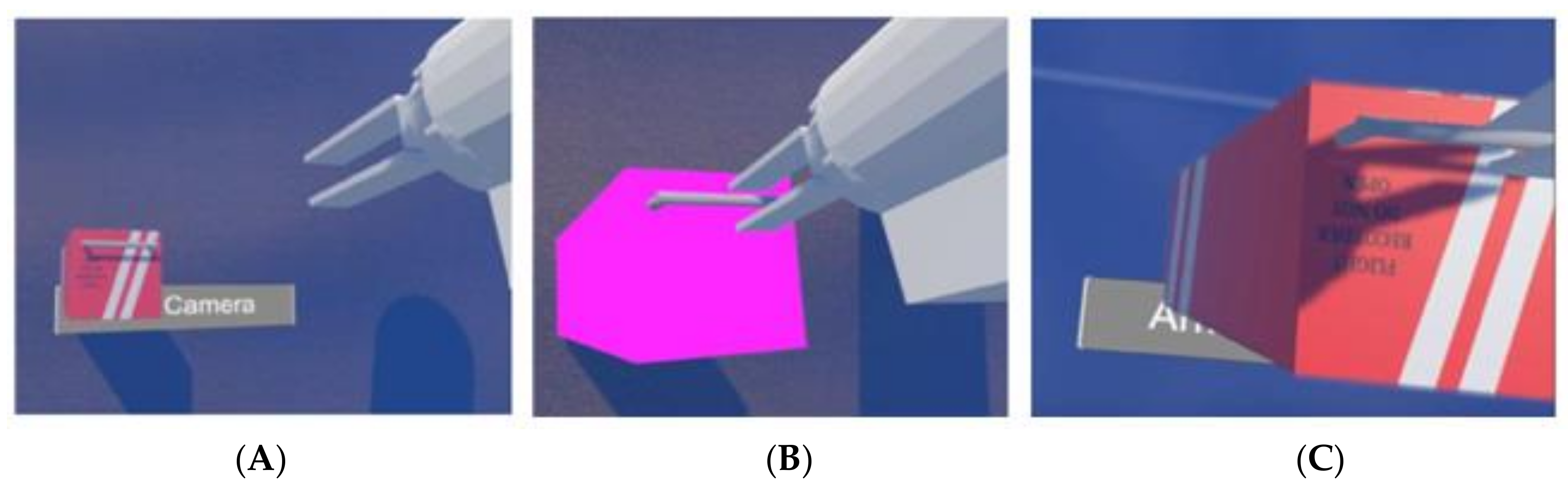
Figure 7.
Black box before being approached by the robotic gripper (A), black box after being approached by the robotic gripper (B), and black box after being grasped and recovered by the robotic gripper (C).
Figure 7.
Black box before being approached by the robotic gripper (A), black box after being approached by the robotic gripper (B), and black box after being grasped and recovered by the robotic gripper (C).

Figure 8.
(A) Girona 500 robot, a reconfigurable AUV designed for a maximum operating depth of up to 500 m. The vehicle is composed of an aluminum frame, which supports three torpedo-shaped hulls of 0.3 m in diameter and 1.5 m in length as well as other elements like sensors and thrusters. (B) Arm5e, arm used with the Girona 500 mobiles robot, here we can appreciate its joins and freedom degrees. Image B adapted from images in https://cirs.udg.edu/auvs-technology/auvs/girona-500-auv/. Image A adapted from [42].

Figure 9.
Mode switch.

Figure 10.
Vehicle controls (A) and arm controls (B).

Figure 11.
First test of the usability test ((A) First version and (B) Second version).

Figure 12.
Second test of the usability test ((A) First version and (B) Second version).

Figure 13.
Third test of the usability test ((A) First version and (B) Second version).

Figure 14.
Fourth test of the usability test: (A) first version and (B) second one (obstacle is the Vertical Wall).
Figure 14.
Fourth test of the usability test: (A) first version and (B) second one (obstacle is the Vertical Wall).

Figure 15.
Average time (minutes), typical deviation, trials for each test and time of the expert user (green line) for the First version.
Figure 15.
Average time (minutes), typical deviation, trials for each test and time of the expert user (green line) for the First version.

Figure 16.
Likert result of the usability tests with the first VR interface.

Figure 17.
Rates of collisions in Test 4 with the different obstacles (Cylinder, Vertical Wall and Horizontal Wall).
Figure 17.
Rates of collisions in Test 4 with the different obstacles (Cylinder, Vertical Wall and Horizontal Wall).

Figure 18.
Average time (minutes), typical deviation, trials for each test and time of the expert user (green line) for the Second version.
Figure 18.
Average time (minutes), typical deviation, trials for each test and time of the expert user (green line) for the Second version.

Figure 19.
Improvement rates in time and trials between the First and the Second VR interface.

Figure 20.
Improvement rates in time and trials between the First and the Second VR interface.

Figure 21.
Likert result of the usability tests with the Second VR interface.

Figure 22.
Collision rates in the Second VR interface.

Figure 23.
Unity development for the TWINBOT concept.

Figure 24.
TWINBOT Simulation Server: (A) Approaching Robots to the pipe; (B) Approaching the grasping points; (C) Closing simultaneously the grippers and (D) Transporting the pipe in a cooperative manner (underwater).
Figure 24.
TWINBOT Simulation Server: (A) Approaching Robots to the pipe; (B) Approaching the grasping points; (C) Closing simultaneously the grippers and (D) Transporting the pipe in a cooperative manner (underwater).


Table 1.
Interface main characteristics in different ROV and AUV projects.
| Project | New Characteristics |
|---|---|
| SAUVIM [3] | Multiple displays, keyboards, joysticks, several expert users for robot. |
| TRIDENT [4] | GUI, one human controller, contextual GUIs |
| MERBOTS [24] | VR cockpit with track and estimation of human poses, one human controller (not expert). |
| Venus [25] | 3D models from sensors data, AR interface |
| OCEAN [5,35] | Bimanual haptic devices, stereoscopic vision, GUI, a world display, constrains: overrides human actions. |
| DexROV [36] | Real time simulation environment, haptic devices (arm and hand exoskeletons), cognitive engine to translate user instructions. |
Table 2.
Usability definitions in different Standards.
| Usability Definitions | Standards |
|---|---|
| The capability of the software product to be understood, learned, used and attractive to the user, when used under specified conditions. | ISO/IEC 9126-1, 2000 |
| The extent to which a product can be used by specified users to achieve specified goals with effectiveness, efficiency and satisfaction in a specified context of use. | ISO 9241-11, 1998 |
| The ease with which a user can learn to operate, prepare inputs for, and interpret outputs of a system or component. | IEEE Std. 610.12-1990 |
Table 3.
Differences between the first and second VR interface.
| First VR Interface | Second VR Interface |
|---|---|
| Information about the vehicle movement speed and rotation. | Information about the vehicle movement speed and rotation and also depth of the vehicle. |
| Solid letters panel. | Transparent letters panel. |
| No sound. | Water, Motor and Impact sound. |
| No added help. | To make easier to understand the hardware: an interface manual and several VR videos (all of them linked in the Supplementary Materials section). |
| Two cameras. | Vehicle camera in different position. |
| Two work modes: vehicle and arm. | Three work modes: vehicle, arm and vehicle camera with arm control. |
Table 4.
First VR interface users: Age of the user, time for each test (T1, T2, T3 and T4), number of trials (Tr) until successful completion, affinity (Af) and pleasantness (Pl). In gray background we can see the expert results.
Table 4.
First VR interface users: Age of the user, time for each test (T1, T2, T3 and T4), number of trials (Tr) until successful completion, affinity (Af) and pleasantness (Pl). In gray background we can see the expert results.
| Age | Sex | T1 | Tr | T2 | Tr | T3 | Tr | T4 | Tr | Af | Pl |
|---|---|---|---|---|---|---|---|---|---|---|---|
| 23 | Male | 352 | 1 | 199 | 1 | 1182 | 7 | 183 | 1 | 0.5 | 7 |
| 43 | Male | 265 | 1 | 385 | 1 | 395 | 2 | 296 | 2 | 0.2 | 8 |
| 27 | Male | 430 | 1 | 650 | 3 | 201 | 1 | 318 | 1 | 0.7 | 9 |
| 22 | Male | 543 | 3 | 138 | 1 | 156 | 1 | 236 | 1 | 1 | 9 |
| 28 | Male | 463 | 1 | 286 | 1 | 274 | 1 | 421 | 1 | 0.4 | 8.5 |
| 45 | Male | 647 | 3 | 360 | 1 | 558 | 2 | 352 | 1 | 0.1 | 7.5 |
| 28 | Male | 250 | 2 | 89 | 1 | 432 | 3 | 367 | 2 | 0.5 | 8 |
| 30 | Female | 965 | 3 | 337 | 1 | 451 | 2 | 724 | 3 | 0 | 8 |
| 24 | Male | 125 | 1 | 122 | 1 | 139 | 1 | 393 | 4 | 0.5 | 9 |
| 29 | Male | 381 | 4 | 491 | 2 | 676 | 2 | 919 | 4 | 0.1 | 8 |
| 38 | Male | 115 | 1 | 103 | 1 | 325 | 2 | 193 | 1 | 1 | 8.5 |
| 24 | Male | 313 | 2 | 97 | 1 | 256 | 1 | 453 | 4 | 1 | 9 |
| 54 | Female | 343 | 3 | 167 | 1 | 780 | 3 | 344 | 1 | 0.2 | 7.5 |
| 46 | Male | 352 | 1 | 196 | 1 | 744 | 4 | 240 | 1 | 0.4 | 8.25 |
| 22 | Male | 192 | 2 | 75 | 1 | 163 | 1 | 141 | 2 | 1 | 9.5 |
| 44 | Male | 430 | 2 | 198 | 1 | 711 | 3 | 811 | 3 | 0.2 | 9 |
| 46 | Male | 197 | 3 | 115 | 1 | 250 | 1 | 167 | 1 | 0.4 | 7 |
| 22 | Male | 144 | 1 | 155 | 1 | 167 | 1 | 153 | 1 | 1 | 9 |
| 22 | Male | 197 | 3 | 80 | 1 | 167 | 1 | 249 | 2 | 1 | 7.75 |
| 23 | Male | 163 | 1 | 135 | 1 | 150 | 1 | 176 | 1 | 1 | 8 |
| 24 | Male | 158 | 1 | 161 | 1 | 190 | 1 | 135 | 1 | 0.8 | 8 |
| 44 | Female | 238 | 1 | 174 | 1 | 745 | 5 | 311 | 1 | 0.2 | 7.75 |
| 33 | Female | 207 | 1 | 298 | 2 | 300 | 1 | 335 | 1 | 0.4 | 7 |
| 31 | Male | 207 | 3 | 80 | 2 | 324 | 3 | 159 | 2 | 1 | 7 |
| 48 | Male | 186 | 1 | 238 | 1 | 462 | 1 | 711 | 4 | 0.4 | 8.5 |
| 22 | Male | 51 | 1 | 46 | 1 | 46 | 1 | 55 | 1 | - | - |
Table 5.
Second VR interface users: Age of the user, time for each test (T1, T2, T3 and T4), number of trials (Tr) until successful completion, affinity (Af), pleasantness (Pl) and if he/she had been member of the first test group (R). In gray background we can see the expert results.
Table 5.
Second VR interface users: Age of the user, time for each test (T1, T2, T3 and T4), number of trials (Tr) until successful completion, affinity (Af), pleasantness (Pl) and if he/she had been member of the first test group (R). In gray background we can see the expert results.
| Age | Sex | T1 | Tr | T2 | Tr | T3 | Tr | T4 | Tr | Af | Pl | R |
|---|---|---|---|---|---|---|---|---|---|---|---|---|
| 22 | Female | 207 | 2 | 190 | 1 | 266 | 1 | 180 | 2 | 0.1 | 8.5 | No |
| 23 | Female | 126 | 1 | 197 | 1 | 446 | 3 | 336 | 1 | 0.1 | 8 | No |
| 27 | Male | 135 | 1 | 98 | 1 | 149 | 1 | 263 | 2 | 0.7 | 9.5 | Yes |
| 21 | Male | 75 | 1 | 73 | 1 | 98 | 1 | 226 | 3 | 0.8 | 7 | No |
| 25 | Male | 138 | 2 | 68 | 1 | 98 | 1 | 113 | 1 | 0.8 | 8.85 | No |
| 20 | Male | 82 | 1 | 198 | 2 | 103 | 1 | 336 | 3 | 1 | 7.5 | No |
| 28 | Male | 71 | 1 | 83 | 1 | 112 | 1 | 101 | 1 | 0.5 | 9 | Yes |
| 25 | Female | 133 | 1 | 162 | 1 | 100 | 1 | 173 | 1 | 1 | 6.75 | No |
| 22 | Male | 75 | 1 | 101 | 1 | 102 | 1 | 109 | 1 | 0.8 | 7 | No |
| 24 | Male | 83 | 1 | 86 | 1 | 89 | 1 | 134 | 1 | 0.8 | 9 | Yes |
| 46 | Male | 285 | 2 | 241 | 1 | 275 | 1 | 257 | 1 | 0.4 | 9 | Yes |
| 38 | Male | 165 | 2 | 226 | 1 | 201 | 1 | 278 | 1 | 1 | 9.5 | Yes |
| 45 | Male | 250 | 1 | 193 | 1 | 233 | 1 | 260 | 1 | 0.1 | 8.5 | Yes |
| 43 | Male | 91 | 1 | 169 | 1 | 290 | 1 | 275 | 1 | 0.2 | 9 | Yes |
| 24 | Male | 111 | 1 | 76 | 1 | 112 | 1 | 152 | 1 | 0.8 | 9 | Yes |
| 48 | Male | 186 | 1 | 238 | 1 | 462 | 1 | 711 | 4 | 0 | 8.5 | No |
| 30 | Female | 159 | 1 | 145 | 1 | 149 | 1 | 292 | 1 | 0.1 | 9 | Yes |
| 22 | Male | 25 | 1 | 31 | 1 | 43 | 1 | 47 | 1 |
© 2020 by the authors. Licensee MDPI, Basel, Switzerland. This article is an open access article distributed under the terms and conditions of the Creative Commons Attribution (CC BY) license (http://creativecommons.org/licenses/by/4.0/).
Share and Cite
MDPI and ACS Style
de la Cruz, M.; Casañ, G.; Sanz, P.; Marín, R. Preliminary Work on a Virtual Reality Interface for the Guidance of Underwater Robots. Robotics 2020, 9, 81. https://0-doi-org.brum.beds.ac.uk/10.3390/robotics9040081
AMA Style
de la Cruz M, Casañ G, Sanz P, Marín R. Preliminary Work on a Virtual Reality Interface for the Guidance of Underwater Robots. Robotics. 2020; 9(4):81. https://0-doi-org.brum.beds.ac.uk/10.3390/robotics9040081
Chicago/Turabian Stylede la Cruz, Marcos, Gustavo Casañ, Pedro Sanz, and Raúl Marín. 2020. "Preliminary Work on a Virtual Reality Interface for the Guidance of Underwater Robots" Robotics 9, no. 4: 81. https://0-doi-org.brum.beds.ac.uk/10.3390/robotics9040081
Note that from the first issue of 2016, this journal uses article numbers instead of page numbers. See further details here.