Parallel Manipulation Based on Stick-Slip Motion of Vibrating Platform


eFactory Laboratory, Mechatronics Engineering Technology, Bowling Green State University, Bowling Green, OH 43403, USA
Robotics 2020, 9(4), 86; https://0-doi-org.brum.beds.ac.uk/10.3390/robotics9040086
Submission received: 21 September 2020
/
Revised: 13 October 2020
/
Accepted: 15 October 2020
/
Published: 18 October 2020
(This article belongs to the Section Industrial Robots and Automation)
Abstract
:The majority of the industrial material handling mechanisms used in the manipulation or assembly of mesoscale objects are slow and require precision programming and tooling, mainly because they are based on sequential robotic pick-n-place operations. This paper presents problem formation, modeling, and analysis of a sensorless parallel manipulation technique for mimicking real-systems that transfer mesoscale objects based on the vibration of inline-feeder machines. Unlike common stick-slip models that utilize a “mass-on-moving-belt” and avoid totality of the motion, the research obtains differential equations in order to describe the combined physics of stick-slip dynamics of an object traveling along an oscillating platform under smooth and dry friction conditions. The nonlinear dynamics are solved numerically to explain the effect of system parameters on the stick-slip motion. The research provides empirical models based on frequency-analysis identification to describe the total linear speed of an object to an input force. The results are illustrated and tested by time–response, phase plots, and amplitude response diagrams, which compare very favorably with results obtained by numerical simulation of the equation of motion, and this suggests that the vibration of the platform is independent of stick-slip motion when the mass of the object being transported is small relative to the mass of the system.
1. Introduction
Spatial manipulation of objects is of such ubiquitous utility that it is currently in indispensable use in a wide range of areas including industry, research, space, biology, medicine etc. In fact, it is difficult to think of processes, which do not involve some kind of sorting, singulating, orienting, feeding, positioning or assembling of parts. A number of diverse approaches have been employed ranging from a sensor based deterministic pick-n-place Microassembly to vibration assisted manipulation. However, the irregularity of the shape and the weight of objects being grasped often require retooling of the endeffectors that are typically attached to the robots. Sensorless vibration technique are currently used in industrial feeder system to sort and transport parts between given initial and final positions. The use of vibration forces in sorting and assembling parts of tangible sizes is an ongoing phenomenon utilized in mechanical filters and feeders. It is relatively cheap especially for mass sorting scenarios because it does not require sensors or grippers. However, so far the efforts lack in conceptualizing a method which can be successfully used for controlled two dimensional spatial manipulation of a particle atop a membrane by controlling the vibration force input underneath. It has so far only been utilized as a general gross stimulus which targets the entire particle domain as a whole identically without the ability to focus or control a specified point target locally. The currently used methods for manipulation employ a wide spectrum of tools for part sorting such as inline feeder. On the other hand, inline tracking feeders utilize sensorless horizontal vibration to feed particles at a desired total speed where its motion could be analyzed based on incremental dry friction stick-slip principle generated at the contact between the particle and the oscillating plane. When the relative velocity at contact is equal zero, the static friction occurs (stick), otherwise, a slip mode corresponding to dynamic friction takes place. Stick-slip mechanism requires precise control of the force being applied on the particle such that its value is below the static friction force when the oscillating plane motion is directed along the feed direction. This sticktion force will drag the particle at a velocity calculated from the dynamics of the oscillating plane. However, during the slip motion and when plane oscillate away from feed direction, the force applied on the particle must be higher than the static friction force.
Numerous works have been devoted to the study of friction-induced oscillations [1,2,3]. Mitropolskiiand Nguyen describe self-excited oscillations of the mass-on-belt system for a case where there is no sticking between mass and belt [4]. Jin et al. obtained analytical approximation—but limited to short stick condition—to evaluate the stick-slip motion due to a randomly excited and viscously damped duffing oscillator placed on a frictional belt with a uniformly moving speed [5]. lmer discussed stick–slip and pure-slip oscillations of the mass-on-belt system with no damping [6]. There exist some more detailed modeling of frictional behavior based on contact deformation, atomic geometry and microscopic roughness [7,8]. Also, there is vast research devoted to dimensional dynamic system with friction [9,10,11]. For example, Geffen discussed the basic mechanics of friction and friction models [12]. The system dynamics with nonsmooth surfaces or wet film are complex and poses challenges to the stability of system dynamics [13,14,15]. Stick-slip chaotic dynamics in a one degree of freedom very weakly forced oscillator was solved using Melnikov’s techniques [16]. Examples of such self-excited oscillation process include bridge vibration caused by wind forces oscillation and squeak of door hinges, violin string, and electric bell [17,18]. Readable literature reviews on dry friction and stick–slip models and friction force model are given by Feeny et al. [19] and Pennestrì et al. [20].
Manipulation using vibration holds potentials for automatic translocations of particles and construction of complex robots [21]. It has been applied in the sorting, translating, rotating, and trapping submillimeter particles, with application in fluidic medium and dry surfaces [22,23]. Zewei et al. used frequency programmable vibration tweezer to trap and control the trajectory of sub millimeter particles on transversely vibrating plate [24]. Lu et al. studied human-robot user interface to transport micro particles and cells along given path by using controllable ultrasound waves [25]. Baudoin et al. reported precise selective contactless and nondestructive manipulation of human cell in microscopy environment [26]. The application of stick-slip combines the friction and inertial working principle. Recommended literatures can be found in many references including [27,28,29,30,31,32].
The inline feeder system discussed in this research is an industrialized one dimensional deterministic micromanipulation based on the utility of lateral vibration. Researchers attempted to study two dimensional deterministic micromanipulation based on programmable force fields induced by actuator array or transverse vibration [33,34]. In both methods, the distribution of small particles demonstrated different results as frequencies and amplitudes were varied. The results revalidated the theorized propositions for obtaining nodes by vibration forwarded by Rayleigh [35] and Timoshenko [36]. Chladni [37] had originally propounded this idea experimentally. To date, there are limited literatures and industry application that utilizes programmable vibration in two dimensional platforms. Although the friction induced vibration has been well-researched, however, there is need to analytically investigate conditions that governs stick-slip motion under vibrating platform. The contribution of this research has two folds; first, a parametric dynamic model of linear stick-slip motion and solution algorithm are put forward. Second, experimental model based system identification is obtained; validating motion attributes of the analytical model. A model and dynamic characteristics of inline feeder system are presented in this research. Feeder systems are industrialized one dimensional deterministic micromanipulation machine based on the utility of lateral vibration. This paper is organized as follow, first, general classification of micromanipulation is presented in Section 2. A dynamic model of feeder system with switching spring is suggested in Section 3. The condition and the model for stick-slip motion of a particle are discussed. Finally, Section 4 presents a simulation case study with extensive experimental analysis.
2. Classification of Micro-Manipulation
Modern Microassembly or micro-manipulation can be classified into deterministic, stochastic and hybrid [38]. Hybrid Microassembly combines the aforementioned techniques to perform a set of desired tasks. Deterministic assembly refers to priory planned assembly processes between parts and their destinations. Microassembly work-cells with integrated part handling skills and sensor based guided control system architecture enables performing deterministic manipulation tasks. Deterministic Microassembly is also classified into serial and parallel assembly. Parallel Microassembly processes enable a large number of parts to be assembled simultaneously with microscale precision [39]. Parallel assembly comprises the simultaneous precise transfer and alignment of components into binding sites such as active adhesion of nanomaterial under electrostatic field [40]. It enables a large number of parts to be assembled simultaneously with micro-scale precision. Serial Microassembly or one by one micro pick and place requires well defined interface between end-effectors and micro-parts. Such successive process could be classified into automated and manual assembly [41,42,43], where manual assembly is operated by mechanical or optical tweezers guided under a microscope [44]. On the other hand, tele-operated, semi to fully automated microassemblies are operated by work-cells and assisted by proper microgrippers [45]. Methods for controlling the direct pick-n-place operations include vacuum grippers based on micropipette [46], compliant microgrippers [47], and controlled surface tension [48]. Stochastic assembly refers to aggregation of a large number of distributed micro-parts organized by mean of distributed arrays of actuators [49]. Active Surface manipulation is one method implemented to dynamically recruits objects from fixed neighborhood modules using actuator array such as and squeeze forces based on vibrating membranes [21,33,50]. Monolithic Self-assembly are process inspired by laws of nature such as fluidic assembly based on capillary force [51]. Stochastic Parallel Assembly, or most often referred by Multiple Self-Microassembly, is based on trapping micro-parts in defined binding site such as etched hole, chemical, electromagnetic, biomedical, and electrostatic [52,53]. It has been applied in industry for fabrication of Liquid Crystal Display (LCD) substrates with embedded silicon substrate [54]. Such sensorless process enables massive fabrication of Microelectromechanical systems (MEMS) structures.
3. Method
3.1. The Problem
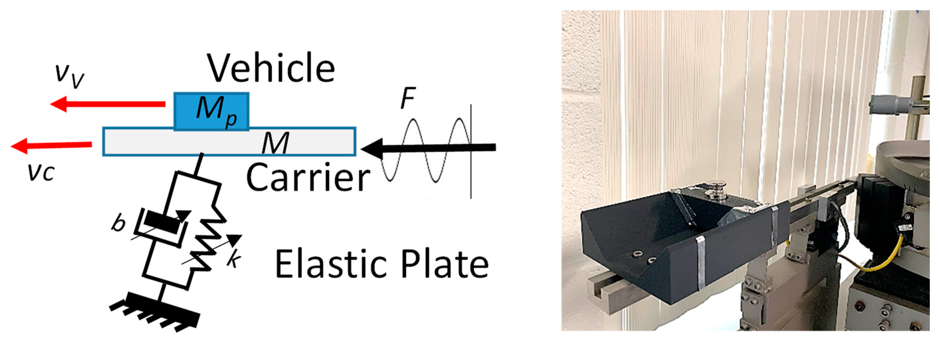
This research models inline feeder system, a sensorless vibration platform that controls the transportation of mesoscale particles along two spatial coordinates. The feeder is a vibrating beam driven by electromagnetic actuator and suspended by elastic plates. Particles which are sorted inside a grooved beam travels massively one-by-one at an average speed controlled by specific frequency and amplitude. A nonlinear forced spring-mass system is derived for the model shown in Figure 1. The derivations are based on well-known classical dynamics of vibrating particle in dry medium. Although numerous friction models have been developed for the control of motion system of small particles, a simple Coulomb friction model is adopted to define the sliding motion of millimeter to centimeter size particles [55,56]. The goal of this section is to obtain a parametric Ordinary Differential Equation (ODE) model optimized to control the speed of the particle.
3.2. Platform Model: Non-Linear ODE
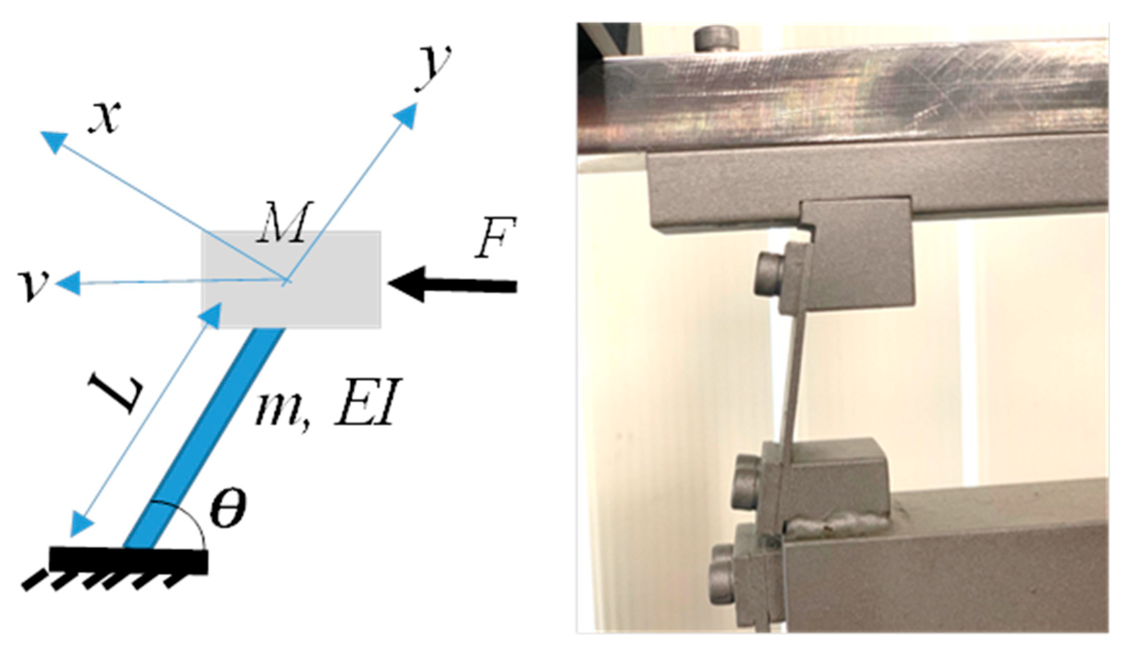
The inline tracking system described in Figure 1 or Figure 2 is comprised of an oscillating beam of mass M suspended on angled plate. The flexural rigidity, EI, offered by the plate is the product of its modulus of elasticity, E, and the second moment of area I. The equivalent second moment of area for q number of stacked plates with thickness h and width w is (qwh3/12). Consider m be the mass of the plate, with a particle—referred by vehicle—of mass Mp is resting on the top of the oscillating beam—referred by carrier. The plate in Figure 2 can be modeled by a cantilevered Bernoulli-Euler beam carrying a mass M at the free end. If the mass of the plate is small in comparison to the tip mass M, the equivalent spring stiffness coefficient on the tip mass along x-axis reduces to all in comparison to the tip mass M, the equivalent spring stiffness coefficient on the tip mass along x-axis reduces to [57,58]
The mass of the plate can be accounted for in the model by introducing a coefficient multiplied by the plate mass and added to the total mass of the carrier and the vehicle. Thus, the equivalent mass at the tip of the cantilever becomes . The exact fundamental Eigen frequency or the natural frequency for spring-mass system under no damping is
In the context of bending vibrations of the cantilever carrying a proof mass [, the coefficient is well known and it is equal to (33/144) [59].
Let the tip mass in Figure 2 be given a small perturbation along x-axis from an equilibrium position. This causes it to displace by with restoring spring force along the oscillating plane is given by
The sum of all forces along v-axis is equal to total inertia. Thus,
where is strong external excitation force applied along v-axis. In feeder system, the force is predominately induced by electromagnetic coil actuator driven by sinusoidal voltage input. The natural frequency of the single lumped spring-mass system in Equation (4) observed along the oscillating plane can be rewritten in parametric form by
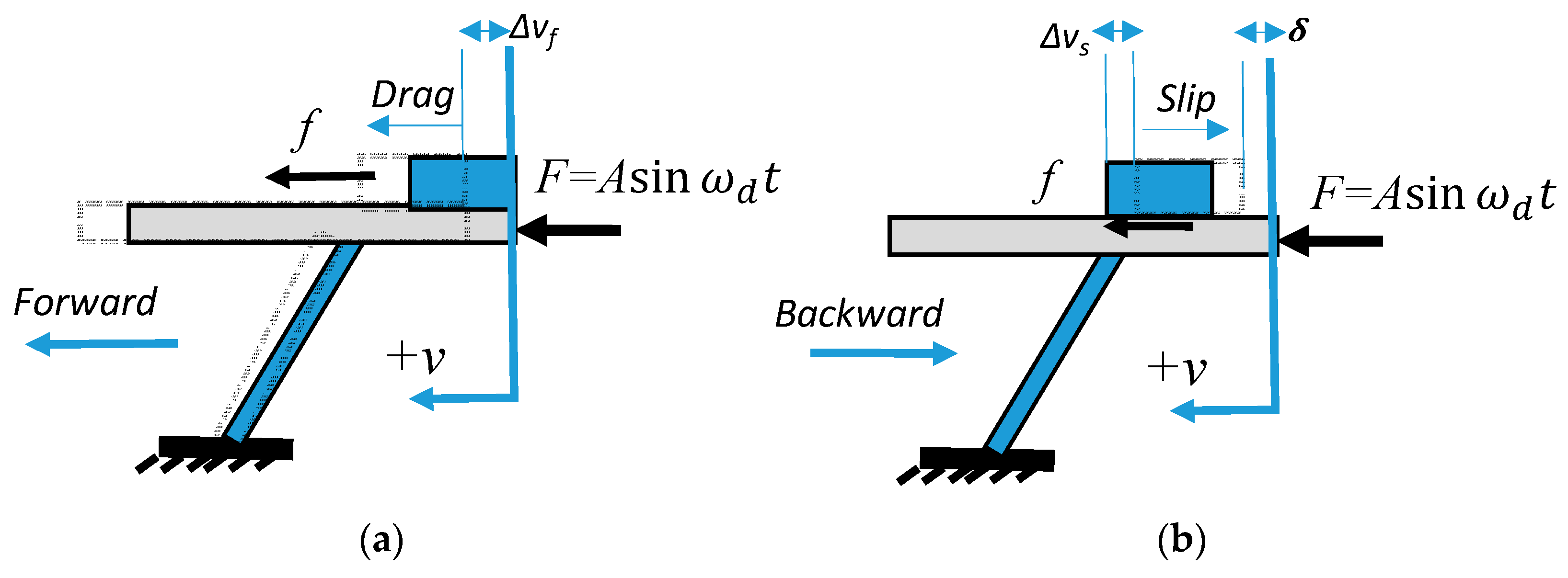
The linear forward locomotion of the particle, which is assumed positive in the direction of the v-axis, can be achieved by using incremental but cyclic forward-stick and backward-slip motions. During the forward-stick period in Figure 3a, the maximum static friction of the particle at the contact surface should be greater than the forward frictional force. Thus, the vehicle adheres to the carrier where both translocate together by a magnitude of per unit cycle in the positive direction of v-axis. On the other hand, the particle slips over the beam surface during the backward-slip motion due to an increase in the acceleration of the beam. This causes the vehicle to slip by a magnitude of per unit cycle in the negative direction of v-axis as illustrated in Figure 3b. Therefore, the net forward motion of the vehicle per unit cycle is . The rapid repetition of the stick-slip cycle causes the vehicle to move discretely at an average speed when both the driving input frequency and its amplitude are constant over time.
The stick-slip motion is satisfied when the value of the frictional force at contact is direction dependent. One technique to control the magnitude of contact friction is to control the carrier acceleration bi-directionally such that the backward acceleration is higher than the maximum allowable forward acceleration that causes slippage, i.e., the forward acceleration is any acceleration less than . This directional control of beam acceleration could be obtained by using several techniques such as: (1) time-variant control of an input shape force function, (2) use of non-linear spring with hysteresis, (3) insertion of omnidirectional damper or shock absorber, or (4) a design fixture that allows a linear elastic plate to have two effective spring constants dependent on the direction of motion.
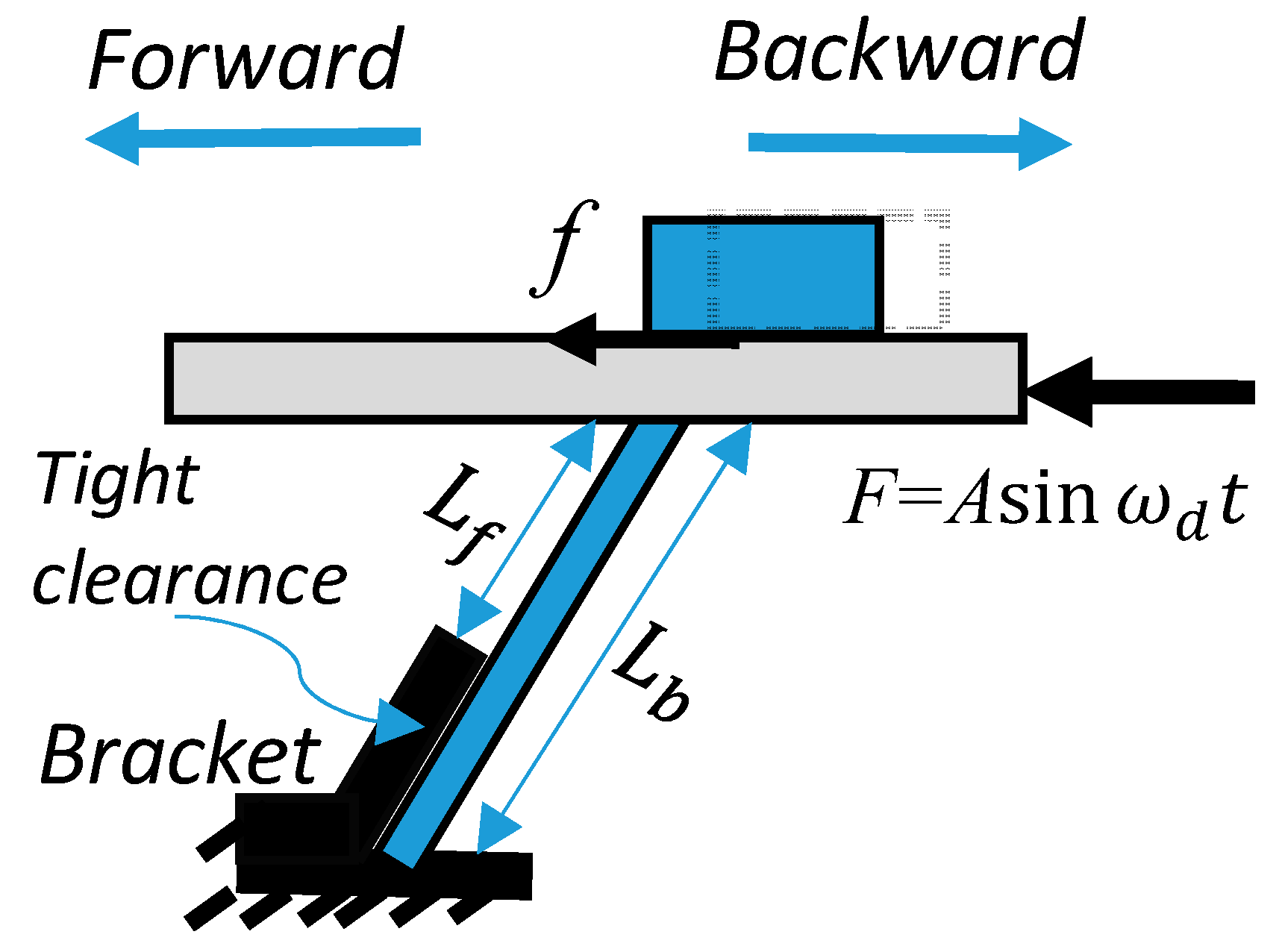
The last technique above is implemented by introducing a bracket in tight contact with the elastic plate as illustrated in Figure 4. This causes the stiffness to change depending on the velocity direction () of the bending. Where the effective lengths that correspond to forward and backward bending are and , respectively.
The equivalent spring constant for the forward and the backward bending are obtained by substituting the effective lengths in Equation (1). Therefore, the natural frequency of the oscillating system switches according to Equation (5).
Assume the vehicle travels together with the carrier, i.e., no slippage, then the combined system under very small bending can be modeled by inhomogeneous non-linear second order differential equation under external sinusoidal force. Let the displacements of carrier and vehicle be represented by , then the combined dynamic model can be described by
where theoretically the equivalent spring constant switches its value between the forward spring constant and backward spring constant depending on the direction of the beam displacement, i.e.,
A better approximation of could be obtained by using conventional Heaviside function with . The approximate equivalent spring constant can be rewritten
The discrete form of the Heaviside function could be replaced by a smooth analytical approximation such as logistic function. The equivalent spring constant can be rewritten in a continuous form
where a larger k corresponds to a sharper transition at v′ = 0. If H(0) = 1/2, equality holds in the limit as β → ∞. Finally, the second order nonlinear linear differential equation that represents system traveling together under alternating spring constant is written in a continuous form as following
The above one-dimensional nonlinear differential equation is accurate when the vehicle is adhering to the carrier surface, or when . The latter condition is sufficient to neglect the force caused by during slipping mode.
3.3. Stick-Slip Model: Linear ODEs
The solution of the nonlinear ODE in Equation (10) provides the displacement of the “vehicle and carrier” platform under no slippage assumption. However, a more detailed parametric model is required to understand the stick and slip dynamics in conjunction of the vibration of the platform. The forward and backward displacements undergo a cyclic pattern that can be separated by modeling each motion with a linear ODE. Because the carrier displacement is cyclic and continuous over time, the solution at the end of the forward period becomes initial condition for the backward period and vice versa. Newton’s second law is applied for forward motion without slippage, and then backward motion with slippage.
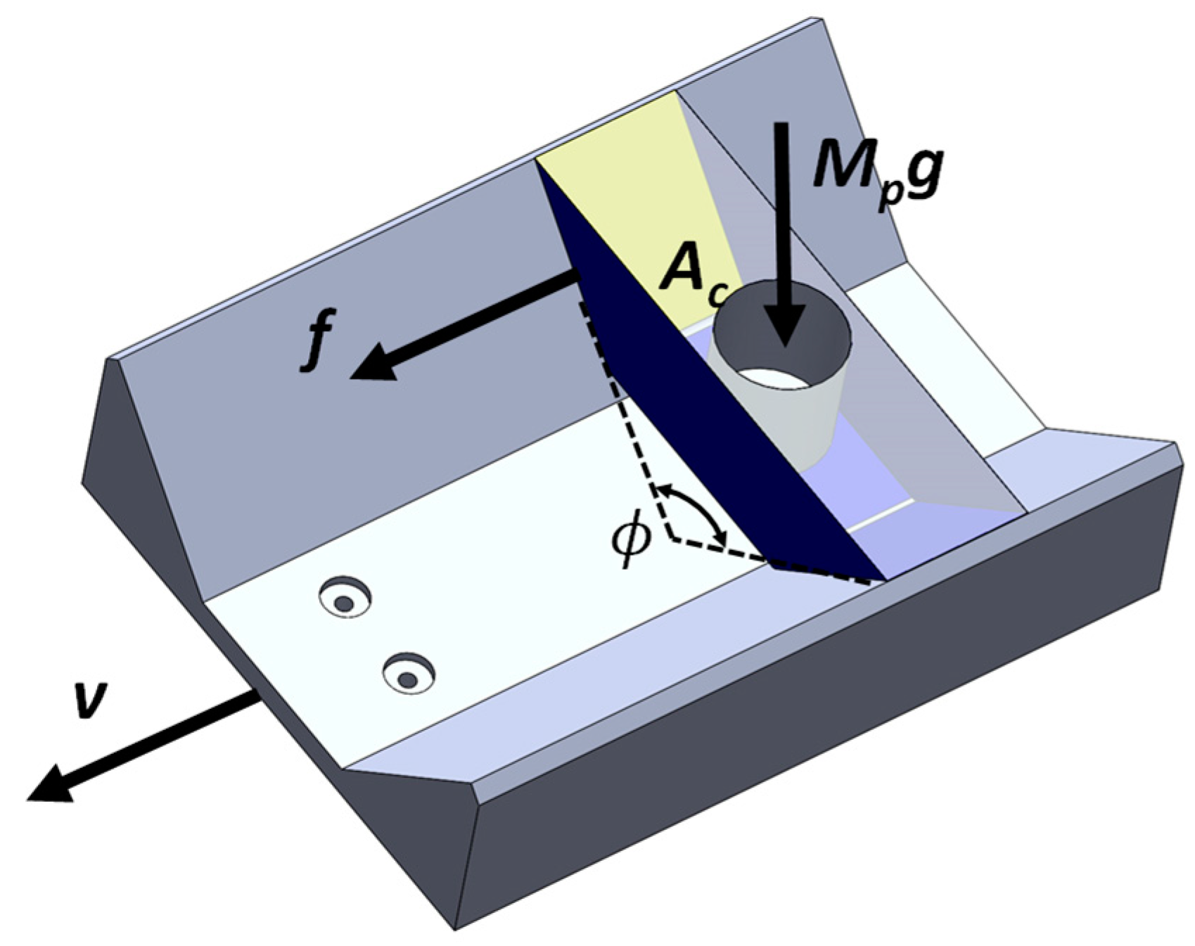
During the forward motion, it is desired to find the maximum allowable forward acceleration below which the vehicle does not slip. The static friction force fs at the contact surface pushes the vehicle to stay together with the carrier. Assume an ideal model where a simple isotropic dry friction condition exists at contact surface, and with static and dynamic coefficients of friction be and , respectively. The is calculated at the maximum static friction. Thus, the acceleration for the entire assembly described in Figure 5 during the forward motion of vehicle must satisfy the following stiction condition at any time during the forward motion:
where the forward motion in the decoupled system refers to the carrier displacement, and it is equal to the displacement of vehicle if the stiction condition in Equation (11) is satisfied. During the forward time , or , the spring constant is equal to . The forward displacement of the vehicle per unit cycle becomes equal to . A cycle is defined here by a period of time comprised of successive forward and backward motions.
The forward acceleration is found from the second order linear differential equation that represents a system traveling together under no slippage
Equation (12) is a forced spring-mass system with natural frequency obtained by substituting in Equation (5). The general solution is comprised of homogenous and particular functions:
where and are constants obtained from initial conditions (displacement and velocity ) updated at every time the carrier changes its direction () or when the conditions of the contact slippage change. The first fundamental frequency for the forward motion is obtained by substituting in Equation (5). The system is assumed to start in forward motion from a stationary boundary conditions, i.e., During the first cycle k = 1, the time at which the direction first switches from forward to backward is obtained from the roots of the derivative of Equation (13). When the velocity becomes negative ( or ), the dynamic model in Equation (13) transitions into the backward ODE model until the velocity switches back into a positive value. The backward ODE model is obtained from the free body diagram under slippage conditions. The dynamic equation of the carrier can be represented by
Equation (14) is a forced spring-mass system with external friction. The general solution is comprised of homogenous and particular functions
The first fundamental frequency for the backward motion is computed by substituting and in Equation (5). The backward motion occurs during negative velocity, , until it switches back into a positive value at the end of the first cycle . In this period, the slippage conditions are assumed to take over. The force analysis of a vehicle undergoing slippage during the backward motion is described by
The double integral of the left hand side of Equation (16) calculates the slipped displacement during the backward motion period. The slippage displacement per unit cycle or is
where and .
The total displacement traveled by the vehicle during the first cycle is ||||. The total distance traveled over a period of time can be obtained in the same manner by recalculating for every cycle k within . Assume the velocity profile of the carrier has n roots within period of time = , and let the vibration start with the forward direction at , then the total displacement of vehicle is:
where the roots of velocity belongs to set . Equation (18) is a simplified arithmetic for calculation of the total distance traveled over where it assumes that the vehicle undergoes pure drag in the forward motion, and pure slip in backward motion. In general, stick-slip could occur either direction and the distance travelled by vehicle can be calculated in similar approach discussed earlier, as will be demonstrated in the simulation case study. Also, it should be noted that although Equation (16) does not consider the mass of the vehicle, it contributes to the solutions in Equations (13) and (15).
3.4. Nondimensional Analysis
Previously, it was found that the stick-slip depends on the vibration of the platform regardless of the mass of the vehicle. Thus, the design of a platform that meets the stick-slip requirement depends on the platform dynamics, more accurately when . Assume the mass of the vehicle be negligible. Let and represent the nondimensional scaled quantities for the displacement and time, respectively. The zeroth order (no damping) linear differential equations are rewritten from Equations (12) and (14) in nondimensional format
where the subscript D is substituted with f or b to refer to forward or backward equation, respectively. The conditions used in variable transformation are and . The nondimensional frequency is equal to , and the characteristic coefficients and are normalized intrinsic units defined by:
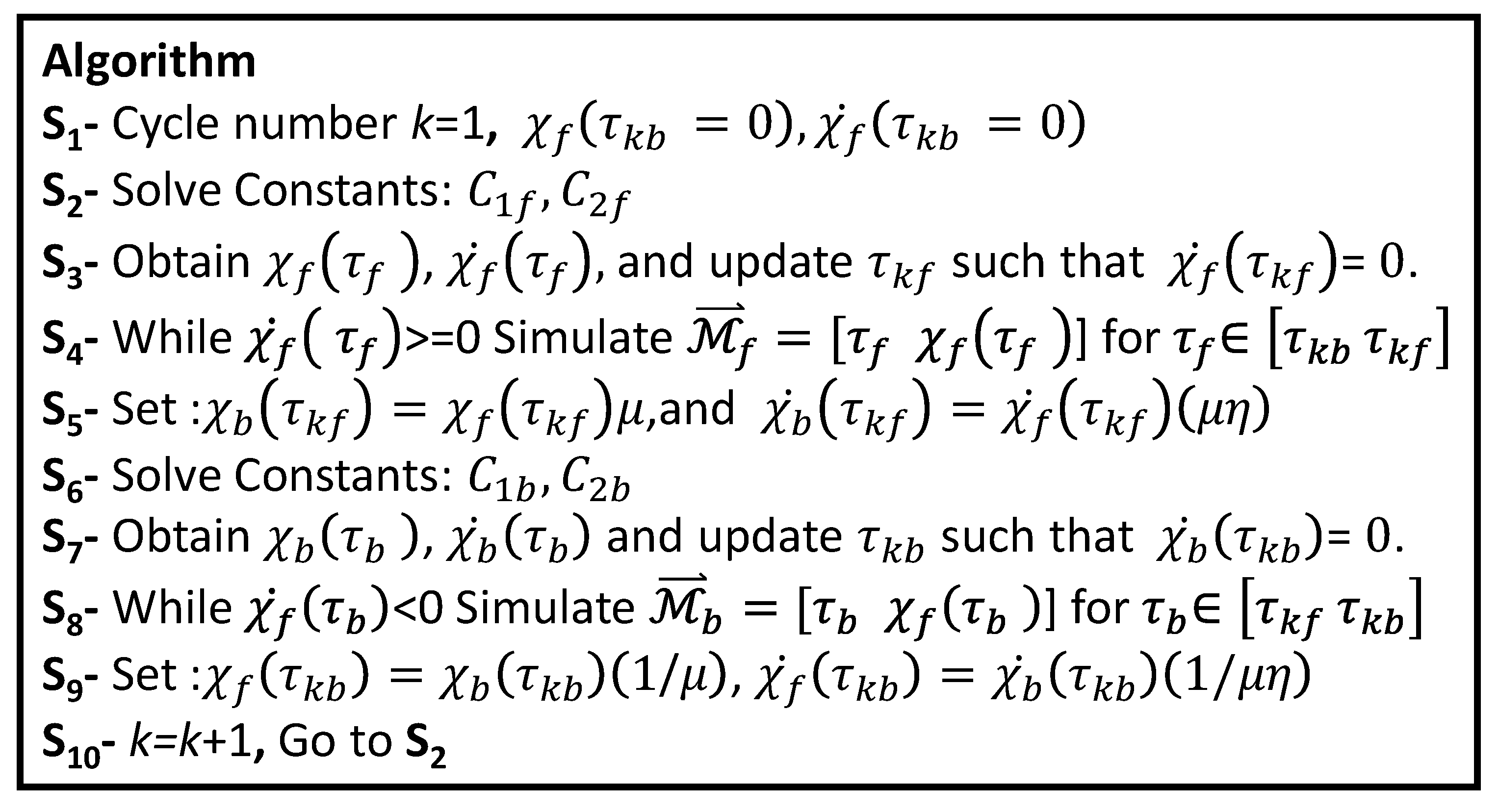
Further simplification is obtained by introducing ratio or , and . = if the flexure rigidity is constant. The algorithm in Figure 6 provides procedures for simulating platform vibration based on Equation (19). A nondimensional slip condition of Equation (11) can be simplified into and then compared with solution of equation to determine vehicle velocity using dimensionless form of Equation (18).
4. Simulation Example
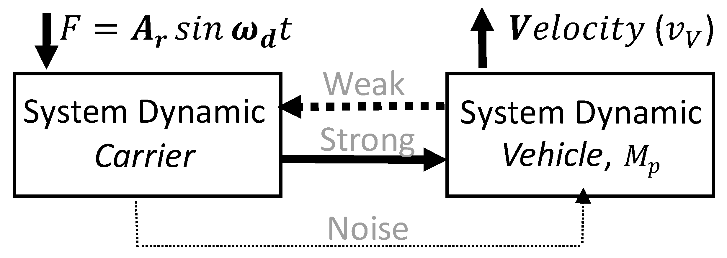
An optimal parametric design of a feeder system is when there exists an input function (say sinusoidal force with frequency(s) and amplitude(s) ) such that the total vehicle displacement per unit cycle is positive, i.e., in the forward direction. The stick-slip dynamic model of the vehicle does not affect the dynamical model of the carrier when . Therefore, the carrier’s vibration, as described in the non-linear ODE in Equation (10) or the system of linear ODEs in Equation (19), could provide an open control input to the vehicle system, as suggested in Figure 7.
Let be numerical solution of the nonlinear ODE model in Equation (10). The necessary but not sufficient conditions for a vehicle to move in the forward direction, , is such that S = { for , and for }. The optimal design parameters of the carrier could be searched within the conditions in the set S such that the sum of stick-slip displacements per unit time is maximized.
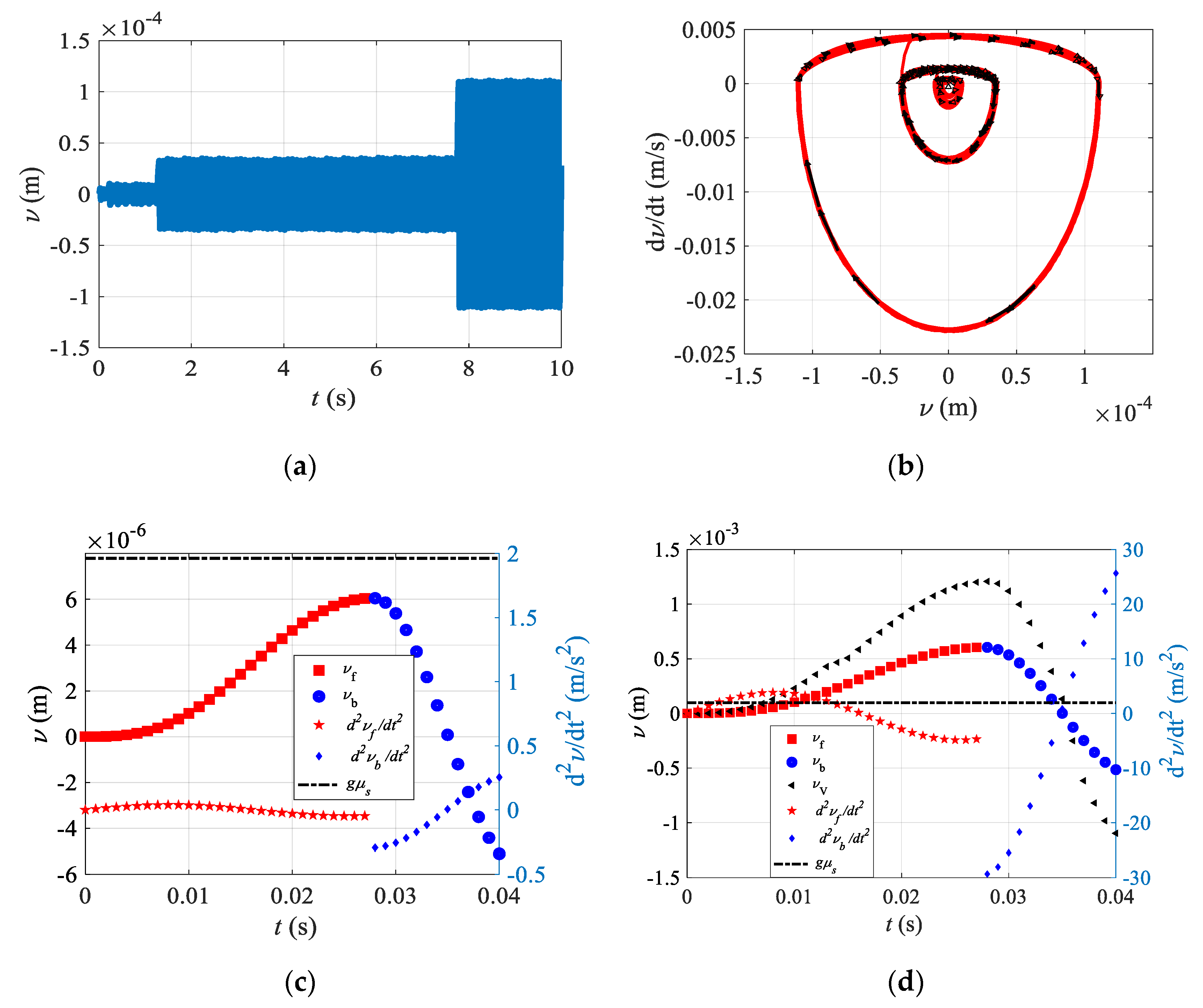
A case study is investigated to solve the nonlinear ODE in Equation (10) numerically by using Matlab ode45 function (Mathworks, 2019). The system parameters used in this case study are , , , , ,, ,, , , , ,, and sampling rate . The corresponding forward and backward frequencies are and , respectively. The numerical solution of the carrier displacement is simulated for time range of [0–100] s. Interestingly, the carrier displacement response abruptly jumped at ~0.2 s, ~1.2 s and ~7.8 s, as shown in Figure 8a. However, the dynamic system is stable around the equilibrium point (0,0) as shown in phase diagram Figure 8b. A small time window is examined and plotted in Figure 8c for a time range [0–0.04] s to compare how the acceleration of the carrier relates to the motion of the vehicle. In general, it should be noted that the forward and backward accelerations are below slip threshold , and therefore, the displacement response of the vehicle follows the displacement response of the carrier. Slip conditions are observed to take place in both directions when the amplitude is increased to N as shown in Figure 8d. The following discussion examines with great depth how stick-slip conditions occur. From initial time until 0.003 s, the forward acceleration value is identified below the value of the slip condition , and therefore the vehicle sticks to the carrier. As the simulation time increases, the vehicle starts slipping until time reaches 0.013 s. This is because the forward acceleration, , is greater than within time period [0.003–0.013] s. As the time progresses during the forward period, the vehicle sticks again until time reaches 0.027 s. At this instant, the motion switches to the backward direction, where backward acceleration, , being less than . This continues until 0.035 s. During this period of time, i.e., [0.027–0.035] s, the vehicle sticks to the carrier. Finally, the backward acceleration becomes greater than the slip condition until the end of the simulation at 0.04 s. During this last period of time, the vehicle exhibits slippage. The accumulated distance traveled by the vehicle, Vv, during the aforementioned stick-slip process is also plotted; showing the location of the vehicle in real-time. It should be pointed out that the parameters selected for this case study are not optimal, and further parametric design analysis are needed to tune the forward motion of the vehicle.
Moorfeed industrial feeder system in Figure 1 is obtained to test the characteristics of the vehicle speed in relation to its weight and the carrier input force characteristics, mainly amplitude and frequency. The input force actuator is delivered by electromagnetic coils attached to the carrier. The system consists of inline tracking and centrifugal bowl each is independently controlled by Rodix feeder cube system. The Rodix operates at input 120 VAC, 50/60 Hz to generate a sinusoidal force output frequency that could be ranging from 5 to 300 Hz and with an output voltage Ve ranging from 0 to 120 VAC. This tunable voltage corresponds to a power amplitude displayed in Rodix cube in terms of percentage 0–100%. The Rodix setting is adjusted to keep both amplitude and frequency within safe operation limits in order to avoid damage of mechanical parts. The tracking system of the Moorfeed is modified to allow for the pure linear translocation of an oriented object with pre-determined geometry and weight.
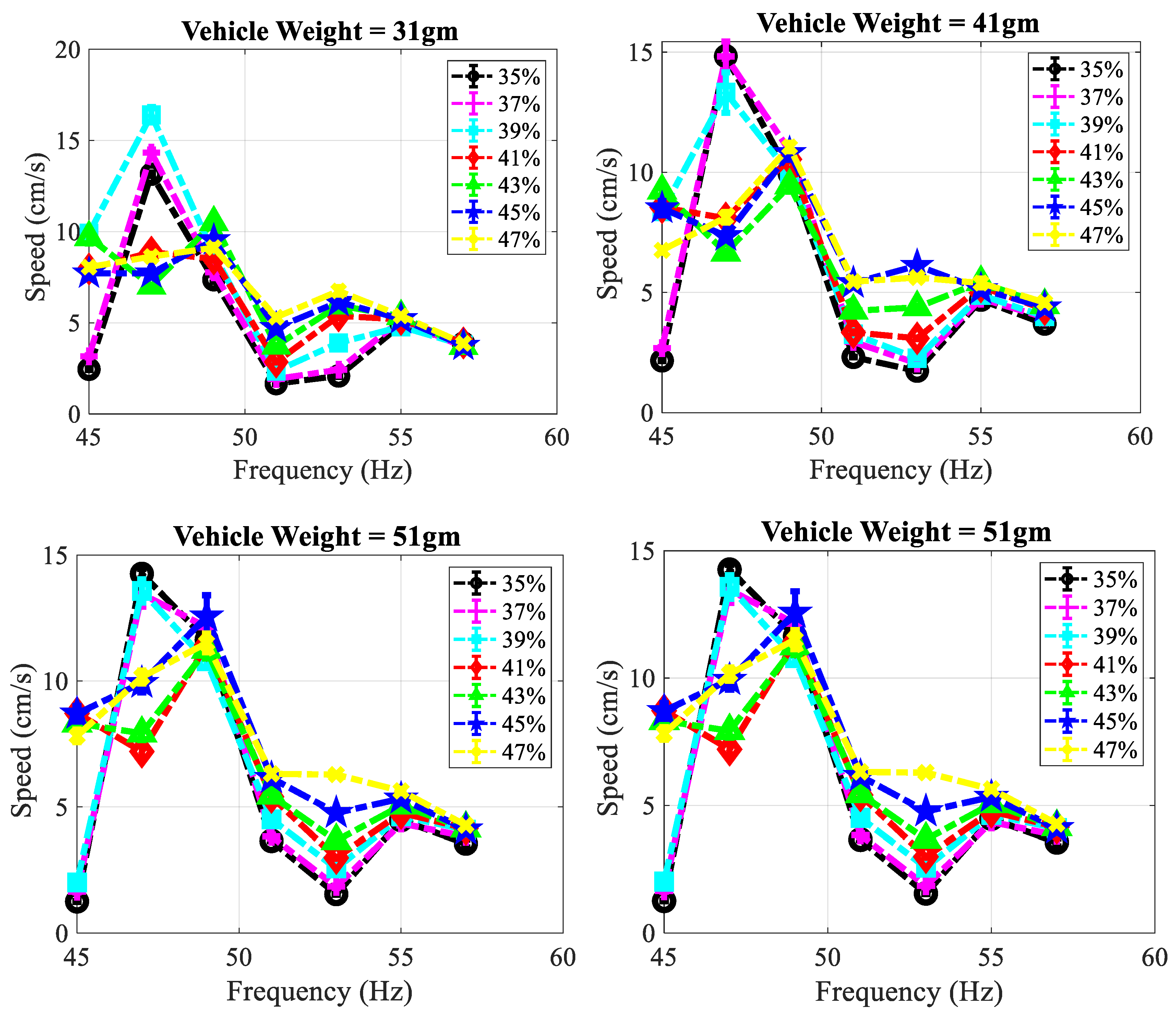
The parts (vehicle block and V-shape carrier adapter) in the CAD design shown in Figure 5 were manufactured from PLA material by using Makerbot Method 3D printer. The printer is based on FDM technology, which produces non-smooth surface. The carrier is covered with aluminum tape mainly to reduce both friction and surface irregularity at contact. The total contact area Ac is measured with a value of 24 cm2. The contact area is kept constant throughout all experiments. The average speed is measured by the time it takes the vehicle to travel a fixed linear distance of 8.5 cm. These measurements are carried out for a range of settings that include vehicle mass , frequency input and power amplitude input percentage Ae%. The is the driving force frequency generated by the electromagnetic actuator measured in Hz. The Ae% is dimensionless and it refers to the percentage ratio Ae = Ve/120 100%. Experiments are conducted to identify average speed model where the average speed is measured against one parameter at a time while others are fixed. The speed is averaged from three separate measurements. A standard weight is secured inside the hole of the vehicle. The experiments in Figure 9 plots the speed of the vehicle in cm/s for a range of input frequency 45–57 Hz and at sample increment of 2 Hz. Each curve represents constant power amplitude Ae which are tested for {35%, 37%, 39%,41%, 43%, 45%, 47%} and a set of mass values = {31, 41, 51, 60} gm which are less than the combined values of and . It should be noted that measurement sets are only collected when the vehicle is moving.
The average speed–frequency plots in Figure 9 shows that the maximum response takes place about frequency ~47 Hz, and decays at higher frequencies. The dynamic system can be identified by 2nd ODE model. It is observed that the vehicle speed is proportional to the amplitude power A%, especially at high frequency region, where the more power amplitude is supplied to the system, the faster the vehicle becomes. However, the relations become nonlinear due to disturbance at resonance frequency 47 Hz. In general, it is observed from Figure 9 that the weight of vehicle has insignificant effect on its average speed. Moreover, as the weight of the vehicle increases, the proportionality between amplitude and average speed becomes more obvious around resonance. This could be because the perturbation orthogonal to the stick-slip motion tends to be insignificant as the vehicle’s weight increases. A comparison between the four plots in Figure 9 confirms that the vehicle’s speed at any given input parameter () does not change significantly with mass of the vehicle . This confirms the validity of the theoretical model where the stick-slip model is independent of the vehicle mass. Also, the system dynamics becomes less dependent on the vehicle mass, particularly when .
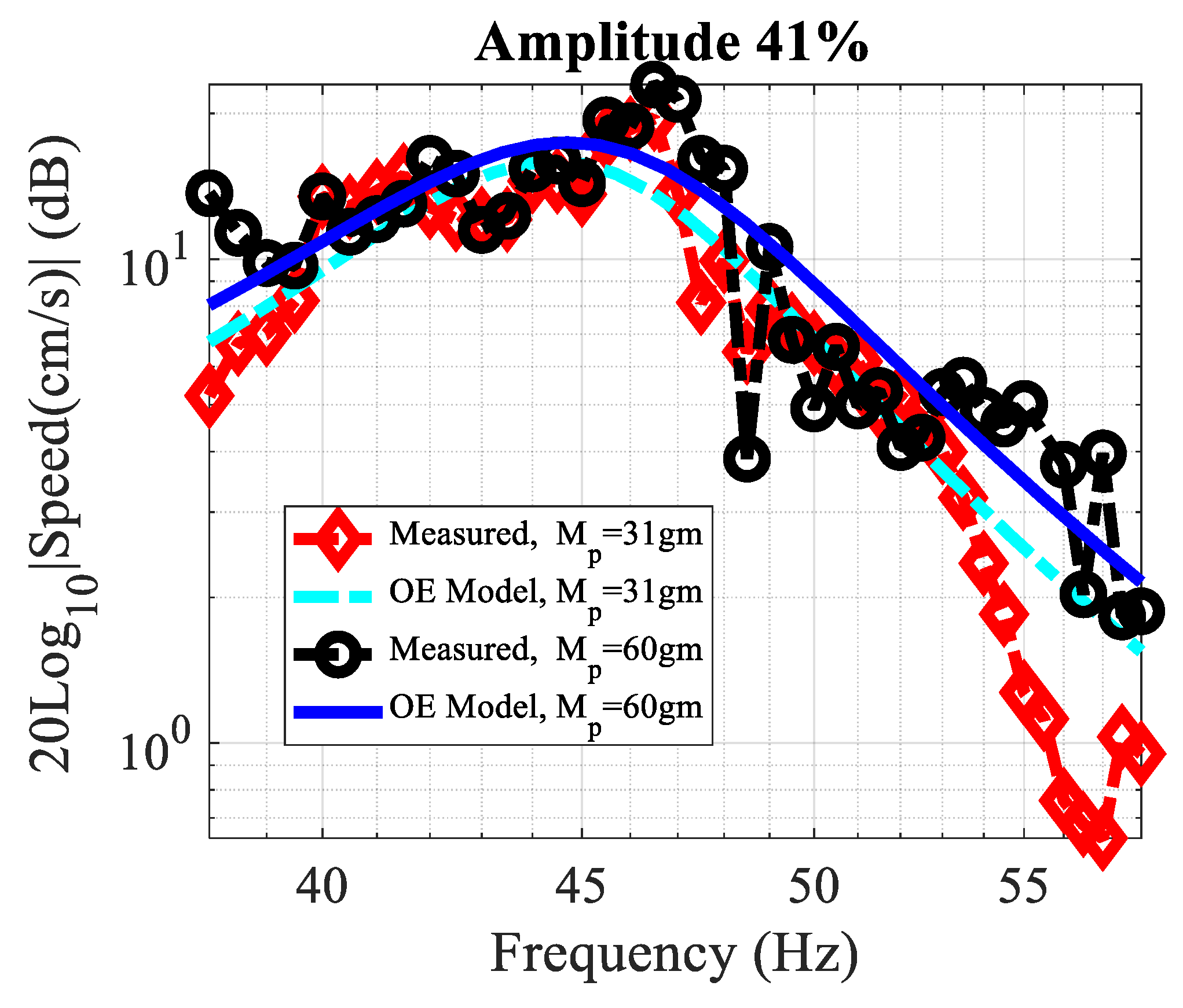
The final set of the experiment deals with system identification of the stick-slip motion model in terms of average velocity output measured for sinusoidal actuation input. The average speed output was measured for a sinusoidal input , where is a discrete frequency input, and t is the time it takes vehicle to travel a distance. Frequency analysis experiments are carried out for two different masses {31,60} gm. The input-output data was collected, and the bode plot is shown in Figure 10. A contentious single-input/single-output (SISO) model is developed for the measurements as follow: the frequency-response of the k-th SISO measurement was first stored in () vector with sample time is set to zero for Linear time invariant (LTI) continuous system. Then, the estimated speed function due to sinusoidal input and additive noise e is represented in continuous model expressed by
The above model could be represented in black-box approximation model constructed from polynomial rational. The model could be written in Laplace transfer function format with n zeros and m poles
where . The frequency-domain data at a frequency tells how a linear system responds to a sinusoidal input of the same frequency. The system identification procedures suggest finding best process model parameters = {,…,,…} that minimize a weighted least square criteria argument (Ljung, 2004)
where K is length of observed measurements, is the estimated parameters and is the weighted value. The speed of the vehicle VV(ω) was measured for range of input frequencies [38–58] Hz at increment size of 0.5 Hz and with constant power amplitude of 41%. The parameter optimization for a linear model was obtained using system identification toolbox in MATLAB software. An estimate output-error OE polynomial model was obtained based on continuous model in Equation (20) with n = 1 and m = 4. Least square criterion was applied to estimate the unknown parameters using frequency response measurements. The estimated OE transfer function for the vehicle with mass 31 gm is
The magnitude bode plot was generated for the estimated model with measurement data plotted in the loglog Figure 10. Moreover, 63% goodness of fit between estimate model and reference data was calculated based on accumulated error from least square method. Similarly, 50% estimated fit for vehicle of weight 60 gm was calculated from OE model.
The poles of the characteristic equation for the transfer functions in Equations (24) and (25) are approximately equal, which confirms that the system dynamic remains unchanged as vehicle mass varies. This validates the linear dynamic model discussed in Figure 7. Also, it is noticed that an increase in input amplitude of a feeder system would help the vehicle to overcome friction and start moving. Moreover, the experimental results and theoretical model confirm that the selection of a proper frequency input is the main factor for determining the stick-slip forward motion once the frictional forces is overcome.
5. Conclusions
This paper developed a model for vibration assisted manipulation techniques to move pre-oriented and singulated meso-scale objects in a linear direction, escorting them from a vibratory or centrifugal feeder into the intended final position through subsequent stick-slip motions. This feeder system was approximated by two models corresponding to the nonlinear vibrating platform and stick-slip motion of a particle. The dynamics of the platform can be assumed independent of the object when its mass is small compared to that of the platform. We developed two techniques to model the vibration of the platform, namely a single non-linear spring-mass ODE and two linear ODEs coupled by initial conditions. The initial conditions are periodically updated to guarantee continuity of the time response as platform is oscillating. The key concept of the stick-slip model is to control the amount of contact frictional force transmitted to the object. This was implemented mechanically by designing a hysteresis-like elastic spring whose value periodically switches depending on the direction of motion of the platform. A numerical simulation is obtained for a case study; showing the relationship between the particle motion, and the acceleration of the platform. The particle moves with a net forward displacement when both (1) the platform acceleration in the forward direction produces inertial force less than the friction force, and (2) the backward acceleration produces inertia larger than friction. This stick-slip motion was observed and confirmed in experiments, where an industrial feeder system is utilized to test the relation between input inertia and particle forward velocity. Frequency-response identification was obtained to model the dynamic model of the particle’s velocity to input force input. The model showed that the system can be approximated by second order ODE, where there exists a frequency at which the velocity is maximum. Finally, both the experimental results, and the parametric model suggest that the mass of particle is become significant when the mass of particle to platform mass ratio is significant. Future work will examine parametric optimization of ODE model under desired stick-slip conditions.
Funding
This research was partially funded by grant from Ohio Department of Higher Education, under grant RAPIDS 2020.
Conflicts of Interest
This work has no conflict of interest.
References
- Knudsen, C.; Feldberg, R.; True, H.; Thompson, J.; Rainey, R.; Soliman, M.; Harrison, A.; Pfeifer, F.; Hajek, M.; Jana, S.; et al. Nonlinear dynamics of engineering systems. Phil. Trans. R. Soc. Lond. A 1992, 338, 451–568. [Google Scholar]
- Hasan, N.A.; Mook, D.T. Nonlinear Oscillations; John Wiley & Sons Incorporated: Hoboken, NJ, USA, 1979. [Google Scholar]
- Nayfeh, A.H.; Mook, D.T. Nonlinear Oscillations; John Wiley & Sons: Hoboken, NJ, USA, 2008. [Google Scholar]
- Mitropolskii, Y.A.; Nguyen, V.D. Applied asymptotic methods in nonlinear oscillations. In Solid Mechanics and Its Applications; Kluwer Academic Publishers Group: Dordrecht, Germany, 1997. [Google Scholar]
- Jin, X.; Xu, H.; Wang, Y.; Huang, Z. Approximately analytical procedure to evaluate random stick-slip vibration of Duffing system including dry friction. J. Sound Vib. 2019, 443, 520–536. [Google Scholar] [CrossRef]
- Elmer, F.-J. Nonlinear dynamics of dry friction. J. Phys. A Math. Gen. 1997, 30, 6057–6063. [Google Scholar] [CrossRef] [Green Version]
- Feder, H.J.S.; Feder, J. Self-organized criticality in a stick-slip process. Phys. Rev. Lett. 1991, 66, 2669. [Google Scholar] [CrossRef]
- Schirmeisen, A.; Jansen, L.; Fuchs, H. Tip-jump statistics of stick-slip friction. Phys. Rev. B 2005, 71. [Google Scholar] [CrossRef]
- Awrejcewicz, J.; Delfs, J. Dynamics of a self-excited stick-slip oscillator with two degrees of freedom. I, Investigation of equilibria. Eur. J. Mech. Solids 1990, 9, 269–282. [Google Scholar]
- Jan, A.; Claude-henri, L. Bifurcation and Chaos in Nonsmooth Mechanical Systems; World Scientific: Singapore, 2003; Volume 45. [Google Scholar]
- Awrejcewicz, J.; Sendkowski, D. Stick-slip chaos detection in coupled oscillators with friction. Int. J. Solids Struct. 2005, 42, 5669–5682. [Google Scholar] [CrossRef] [Green Version]
- Van Geffen, V. A Study of Friction Models and Friction Compensation. Technische Universiteit Eindhoven Eindhoven. Technical Report. 2009. Available online: http://www.mate.tue.nl/mate/pdfs/11194.pdf (accessed on 13 October 2020).
- Berman, A.D.; Ducker, W.A.; Israelachvili, J.N. Origin and characterization of different stick−slip friction mechanisms. Langmuir 1996, 12, 4559–4563. [Google Scholar] [CrossRef]
- Wu-Bavouzet, F.; Clain-Burckbuchler, J.; Buguin, A.; De Gennes, P.-G.; Brochard-Wyart, F. Stick-Slip: Wet Versus Dry. J. Adhes. 2007, 83, 761–784. [Google Scholar] [CrossRef]
- Gourdon, D.; Israelachvili, J.N. Transitions between smooth and complex stick-slip sliding of surfaces. Phys. Rev. E 2003, 68, 021602. [Google Scholar] [CrossRef]
- Awrejcewicz, J.; Holicke, M.M. Melnikov’s method and stick–slip chaotic oscillations in very weakly forced mechanical systems. Int. J. Bifurc. Chaos 1999, 9, 505–518. [Google Scholar] [CrossRef]
- Schelleng, J.C. The bowed string and the player. J. Acoust. Soc. Am. 1973, 53, 26. [Google Scholar] [CrossRef]
- Ding, W. Self-Excited Vibrations; Tsing-Hua University Press: Beijing, China; Springer: Berlin, Germany, 2010; pp. 243–301. [Google Scholar]
- Feeny, B.; Guran, A.; Hinrichs, N.; Popp, K. A Historical Review on Dry Friction and Stick-Slip Phenomena. Appl. Mech. Rev. 1998, 51, 321–341. [Google Scholar] [CrossRef]
- Pennestrì, E.; Rossi, V.; Salvini, P.; Valentini, P.P. Review and comparison of dry friction force models. Nonlinear Dyn. 2015, 83, 1785–1801. [Google Scholar] [CrossRef]
- Chen, Z.; Liu, X.; Kojima, M.; Huang, Q.; Arai, T. Advances in Micromanipulation Actuated by Vibration-Induced Acoustic Waves and Streaming Flow. Appl. Sci. 2020, 10, 1260. [Google Scholar] [CrossRef] [Green Version]
- Zhou, Q.; Sariola, V.; Latifi, K.; Liimatainen, V. Controlling the motion of multiple objects on a Chladni plate. Nat. Commun. 2016, 7, 12764. [Google Scholar] [CrossRef]
- Collins, D.J.; Devendran, C.; Ma, Z.; Ng, J.W.; Neild, A.; Ai, Y. Acoustic tweezers via sub–time-of-flight regime surface acoustic waves. Sci. Adv. 2016, 2, e1600089. [Google Scholar] [CrossRef] [PubMed] [Green Version]
- Hou, Z.; Zhou, Z.; Liu, P.; Pei, Y. Robotic Trajectories and Morphology Manipulation of Single Particle and Granular Materials by a Vibration Tweezer. Soft Robot. 2020. [Google Scholar] [CrossRef]
- Lu, X.L.; Zhao, K.; Liu, W.; Yang, D.; Shen, H.; Peng, H.; Guo, X.; Li, J.; Wang, J. A Human Microrobot Interface Based on Acoustic Manipulation. ACS Nano 2019, 13, 11443–11452. [Google Scholar] [CrossRef]
- Baudoin, M.; Thomas, J.-L.; Al Sahely, R.; Gerbedoen, J.-C.; Gong, Z.; Sivery, A.; Matar, O.; Smagin, N.; Vlandas, A. Cell selective manipulation with single beam acoustical tweezers. arXiv 2020, arXiv:2001.04162 2020, preprint. [Google Scholar]
- Zhang, Z.M.; An, Q.; Li, J.W.; Zhang, W.J. Piezoelectric friction–inertia actuator—A critical review and future perspective. Int. J. Adv. Manuf. Technol. 2012, 62, 669–685. [Google Scholar] [CrossRef]
- Liu, Y.F.; Li, J.; Hu, X.H.; Zhang, Z.M.; Cheng, L.; Lin, Y.; Zhang, W.J. Modeling and control of piezoelectric inertia–friction actuators: Review and future research directions. Mech. Sci. 2015, 6, 95–107. [Google Scholar] [CrossRef] [Green Version]
- Zhong, B.; Zhu, J.; Jin, Z.; He, H.; Sun, L.; Wang, Z. Improved inertial stick-slip movement performance via driving waveform optimization. Precis. Eng. 2019, 55, 260–267. [Google Scholar] [CrossRef]
- Qin, F.; Huang, H.; Wang, J.; Tian, L.; Liang, T.; Zhao, H. Design and stepping characteristics of novel stick-slip piezo-driven linear actuator. Smart Mater. Struct. 2019, 28. [Google Scholar] [CrossRef]
- Shao, Y.; Xu, M.; Shao, S.; Song, S. Effective dynamical model for piezoelectric stick–slip actuators in bi-directional motion. Mech. Syst. Signal. Process. 2020, 145, 106964. [Google Scholar] [CrossRef]
- Lima, R.; Sampaio, R. Stick–slip oscillations in a multiphysics system. Nonlinear Dyn. 2020, 100, 2215–2224. [Google Scholar] [CrossRef]
- Bohringer, K.-F.; Donald, B.R.; Macdonald, N.C. Programmable Force Fields for Distributed Manipulation, with Applications to MEMS Actuator Arrays and Vibratory Parts Feeders. Int. J. Robot. Res. 1999, 18, 168–200. [Google Scholar] [CrossRef]
- Bohringer, K.-F.; Bhatt, V.; Goldberg, K.Y. Sensorless manipulation using transverse vibrations of a plate. In Proceedings of the 1995 IEEE International Conference on Robotics and Automation, Nagoya, Japan, 21–27 May 1995; pp. 1989–1996. [Google Scholar]
- Rayleigh, J.W.S. The Theory of Sound, 2nd ed.; Dover Publications: Mineola, NJ, USA, 1945; Volome 1, pp. 110–111. [Google Scholar]
- Timoshenko, S.P.; Woinowsky-Krieger, S. Theory of Plates and Shells; McGraw-Hill: New York, NY, USA, 1959. [Google Scholar]
- Chladni, E.F.F. Entdeckungen über die Theorie des Klanges; Bey Weidmanns erben und Reich: Leipzig, Germany, 1787. [Google Scholar]
- Mayyas, M.A. Methodologies for Automated Microassembly. Ph.D. Thesis, University of Texas at Arlington, Arlington, TX, USA, 2008. [Google Scholar]
- Cohn, M.B.; Boehringer, K.F.; Noworolski, J.M.; Singh, A.; Keller, C.G.; Goldberg, K.A.; Howe, R.T. Microassembly technologies for MEMS. In Microelectronic Structures and MEMS for Optical Processing IV; International Society for Optics and Photonics: Bellingham, WA, USA, 1998; pp. 2–16. [Google Scholar]
- Smith, B.D.; Mayer, T.S.; Keating, C.D. Deterministic Assembly of Functional Nanostructures Using Nonuniform Electric Fields. Annu. Rev. Phys. Chem. 2012, 63, 241–263. [Google Scholar] [CrossRef]
- Das, A.N.; Zhang, P.; Lee, W.H.; Popa, D.O.; Stephanou, H. μ3: Multiscale, Deterministic Micro-Nano Assembly System for Construction of On-Wafer Microrobots. In Proceedings of the 2007 ICRA. IEEE International Conference on Robotics and Automation (Cat. No.01CH37164), Roma, Italy, 10–14 April 2007; pp. 461–466. [Google Scholar]
- Dechev, N.; Cleghorn, W.; Mills, J. Microassembly of 3-D Microstructures Using a Compliant, Passive Microgripper. J. Microelectromech. Syst. 2004, 13, 176–189. [Google Scholar] [CrossRef] [Green Version]
- Wich, T.; Edeler, C.; Stolle, C.; Fatikow, S. Micro-nano-integration based on automated serial assembly. In Proceedings of the 2009 IEEE International Conference on Automation Science and Engineering, Bangalore, India, 22–25 August 2009; pp. 573–578. [Google Scholar]
- Wendenburg, R.; Michelmann, A.; Greulich, K.O.; Monajembashi, S.; Uhl, V. System for Introducing Optical Tweezers and/or a Treatment Beam Into a Laser Scanning Microscope. U.S. Patent 6,850,363, 1 February 2005. [Google Scholar]
- Mayyas, M.; Zhang, P.; Lee, W.H.; Shiakolas, P.; Popa, D. Design Tradeoffs for Electrothermal Microgrippers. In Proceedings of the 2001 ICRA IEEE International Conference on Robotics and Automation (Cat. No.01CH37164), Roma, Italy, 10–14 April 2007; pp. 907–912. [Google Scholar]
- Fontana, G.; Ruggeri, S.; Pagano, C.; Fassi, I.; Legnani, G. Manipulation of Microcomponents Using Vacuum Grippers. Available online: https://iris.unibs.it/retrieve/handle/11379/179101/4804/Aimeta2011-Bologna-Microgripper-MEM-230-0.pdf (accessed on 13 October 2020).
- Wang, F.; Liang, C.; Tian, Y.; Zhao, X.; Zhang, D. Design and Control of a Compliant Microgripper With a Large Amplification Ratio for High-Speed Micro Manipulation. IEEE/ASME Trans. Mechatron. 2016, 21, 1262–1271. [Google Scholar] [CrossRef]
- Monkman, G. Electroadhesive microgrippers. Ind. Robot. Int. J. 2003, 30, 326–330. [Google Scholar] [CrossRef]
- Donald, B.R.; Levey, C.G.; Paprotny, I. Planar Microassembly by Parallel Actuation of MEMS Microrobots. J. Microelectromech. Syst. 2008, 17, 789–808. [Google Scholar] [CrossRef]
- Chen, L.; Chen, T.; Sun, L.; Rong, W.; Shao, B.; Yang, Q. Active control of adhesion force for pick-and-place of micro objects with compound vibration in micromanipulation. In Proceedings of the 2010 IEEE International Conference on Automation Science and Engineering, Toronto, ON, Canada, 21–24 August 2010; pp. 716–721. [Google Scholar]
- Khalil, K.S.; Mahmoudi, S.R.; Abu-Dheir, N.; Varanasi, K.K. Active surfaces: Ferrofluid-impregnated surfaces for active manipulation of droplets. Appl. Phys. Lett. 2014, 105, 041604. [Google Scholar] [CrossRef]
- Boncheva, M.; Whitesides, G.M. Making Things by Self-Assembly. MRS Bull. 2005, 30, 736–742. [Google Scholar] [CrossRef] [Green Version]
- Rida, A.; Gijs, M.A.M. Manipulation of Self-Assembled Structures of Magnetic Beads for Microfluidic Mixing and Assaying. Anal. Chem. 2004, 76, 6239–6246. [Google Scholar] [CrossRef]
- Čižmár, T.; Romero, L.C.D.; Dholakia, K.; Andrews, D.L. Multiple optical trapping and binding: New routes to self-assembly. J. Phys. B At. Mol. Opt. Phys. 2010, 43, 102001. [Google Scholar] [CrossRef]
- Gagnon, L.; Morandini, M.; Ghiringhelli, G.L. A review of friction damping modeling and testing. Arch. Appl. Mech. 2019, 90, 107–126. [Google Scholar] [CrossRef] [Green Version]
- Liu, Y.F.; Li, J.; Zhang, Z.M.; Hu, X.H.; Zhang, W.J. Experimental comparison of five friction models on the same test-bed of the micro stick-slip motion system. Mech. Sci. 2015, 6, 15–28. [Google Scholar] [CrossRef] [Green Version]
- Gurgoze, M. On the eigenfrequencies of a cantilever beam with attached tip mass and a spring-mass system. J. Sound Vib. 1996, 190, 149–162. [Google Scholar] [CrossRef]
- Gurgoze, M. On the approximate determination of the fundamental frequency of a restrained cantilever beam carrying a tip heavy body. J. Sound Vib. 1986, 105, 443–449. [Google Scholar] [CrossRef]
- Gürgöze, M. On the representation of a cantilevered beam carrying a tip mass by an equivalent spring–mass system. J. Sound Vib. 2005, 282, 538–542. [Google Scholar] [CrossRef]
Figure 1.
Schematic of the inline tracking feeder system under small perturbation.

Figure 2.
Representation of beam of mass m suspender on a spring-plate.

Figure 3.
Cyclic increments: (a) forward-stick drag motion. (b) backward-slip motion.

Figure 4.
Bi-directional elastic plate with two spring constants.

Figure 5.
CAD assembly of carrier adapter and vehicle designs.

Figure 6.
Suggested simulation algorithm of forward and backward ODEs systems coupled by initial conditions.
Figure 6.
Suggested simulation algorithm of forward and backward ODEs systems coupled by initial conditions.

Figure 7.
Control model diagram showing coupled nonlinear system dynamics of stick-slip locomotion.

Figure 8.
Nonlinear dynamics. (a) displacement response of the carrier. (b) phase plot of the carrier simulated over [0–100] s. (c) The displacement and acceleration of carrier (similar to vehicle) simulated for . (d) Displacement and acceleration simulated for .
Figure 8.
Nonlinear dynamics. (a) displacement response of the carrier. (b) phase plot of the carrier simulated over [0–100] s. (c) The displacement and acceleration of carrier (similar to vehicle) simulated for . (d) Displacement and acceleration simulated for .

Figure 9.
Frequency response analysis obtained for the average speed it takes the vehicle to travel 8.5 cm. The experiments are conducted for a range of frequencies [45–57] Hz, set of power amplitudes {35, 37, 39, 41, 45, 47}%, and tested for weights of {31, 41, 51, 60} gm.
Figure 9.
Frequency response analysis obtained for the average speed it takes the vehicle to travel 8.5 cm. The experiments are conducted for a range of frequencies [45–57] Hz, set of power amplitudes {35, 37, 39, 41, 45, 47}%, and tested for weights of {31, 41, 51, 60} gm.

Figure 10.
loglog magnitude frequency response of the experiments with estimated models obtained from system identification analysis. Each sample data is averaged from three independent tests.
Figure 10.
loglog magnitude frequency response of the experiments with estimated models obtained from system identification analysis. Each sample data is averaged from three independent tests.

Publisher’s Note: MDPI stays neutral with regard to jurisdictional claims in published maps and institutional affiliations. |
© 2020 by the author. Licensee MDPI, Basel, Switzerland. This article is an open access article distributed under the terms and conditions of the Creative Commons Attribution (CC BY) license (http://creativecommons.org/licenses/by/4.0/).
Share and Cite
MDPI and ACS Style
Mayyas, M. Parallel Manipulation Based on Stick-Slip Motion of Vibrating Platform. Robotics 2020, 9, 86. https://0-doi-org.brum.beds.ac.uk/10.3390/robotics9040086
AMA Style
Mayyas M. Parallel Manipulation Based on Stick-Slip Motion of Vibrating Platform. Robotics. 2020; 9(4):86. https://0-doi-org.brum.beds.ac.uk/10.3390/robotics9040086
Chicago/Turabian StyleMayyas, Mohammad. 2020. "Parallel Manipulation Based on Stick-Slip Motion of Vibrating Platform" Robotics 9, no. 4: 86. https://0-doi-org.brum.beds.ac.uk/10.3390/robotics9040086
Note that from the first issue of 2016, this journal uses article numbers instead of page numbers. See further details here.