A New Soft RCC Device with Pneumatic Regulation


DIMEAS-Department of Mechanical and Aerospace Engineering, Politecnico di Torino, 10129 Turin, Italy
*
Author to whom correspondence should be addressed.
Robotics 2020, 9(4), 98; https://0-doi-org.brum.beds.ac.uk/10.3390/robotics9040098
Submission received: 24 September 2020
/
Revised: 7 November 2020
/
Accepted: 14 November 2020
/
Published: 21 November 2020
(This article belongs to the Section Soft Robotics)
Abstract
:The work described in this paper aims at exploiting the characteristic of a special deformable actuator with rolling membranes to realize a device with defined Remote Center of Compliance (RCC). Starting from theoretical approaches to the definition of the RCC, the authors propose a novel and simple formulation that can be applied to the soft actuator to determine its RCC. The position of the device’s RCC was determined by creating an asymmetry on the geometry of the device along its axis, i.e., by imposing a longitudinal displacement to the piston with respect to the membranes’ rest condition. FEM simulations of the device behavior were carried out and a first formulation describing the placement of the RCC by varying the operating pressure was found. Finally, a comparison of the theoretical model and FEM results is presented, validating the proposed formulation.
1. Introduction
The concept of the Remote Center of Compliance (RCC) has been investigated by researchers for a number of years and has been used in simple applications, such as inserting a peg in the hole [1]. The RCC is a localized point in the geometrical representation of a device, in which the application of external forces (or torques) produces a displacement related only to the applied external action (force or torque). Its position strongly depends on the geometry and the stiffness of the system and its components. Drake introduces the RCC as “a point in which an applied force causes only a lateral displacement while an applied moment causes only a rotation” [2]. Drake was one of the first researchers who investigated the properties of the compliance center, proposing mechanical systems with architectures capable of positioning it according to the work to be performed.
In the literature, the typical task used to describe the RCC is the insertion of a peg into a hole that can occur during an assembly operation [3,4]. If a misalignment between the peg and the hole axes occurs, and if the device is developed with the RCC concept (with the RCC placed at the physical end of the peg), the compliance of the system enables the peg to spontaneously re-align its axis with the hole axis without using any force sensory feedback. Aiming to completely automate the assembly functions in industries, this type of device is relevant to several applications: clearance fits, bearings in housings, shafts in bearings, mounting splines, or inserting screws into threaded cavities [5].
Several studies have highlighted that placing the center of compliance on the tip of the shaft avoids unwanted conditions, such as jamming or wedging [6,7]. Sorli and Govi [8] studied contact forces during insertion, making a comparison between different passive compliance designs. They analyzed different cases according to the initial position of the peg (1-point contact or 2-point contact), and for each derived a model capable of estimating optimal insertion parameters. They showed how an RCC system requires a lower insertion force. In [9], elastomeric shear pads are chosen instead of beams, which constitute the classical components of devices for applications with an RCC. This arrangement allows a lower lateral stiffness to be obtained to more quickly compensate for the misalignment of the device. However, the material properties of the elastomeric shear pads must be taken into account because they strongly influence the final placement of the center.
In many applications, the RCC position is fixed, which means that different RCC devices must be used for different peg lengths. In [10], an adjustable RCC device is presented, and the advantages and disadvantages of this type of device are outlined [11]. In particular, some of the errors of the axis misalignment between peg and hole may not be compensated for. In a structure with a constant stiffness and an established geometry, the position of the RCC is defined and fixed, which implies that the device can be used only for that specific task [12]. Practical solutions to change the position of the compliance center have been designed, including the improvement made along the axis of elastomeric shear pads [13]. By adjusting the insertion depth of a rod in a hole, a variable number of layers is clamped. In this way, lateral stiffness is controlled and different positions of the center of compliance are achieved.
Recently, Camilo et al. [14] presented a deep reinforcement learning approach for the variable compliance control for robotic peg-in-hole assembly, defining the RCC position using software rather than hardware. In Zhang et al. [15], the peg–hole disassembly was presented using active compliance, and, in particular, a quasi-static analysis of peg–hole disassembly with a compliant manipulator was performed. In Lai LJ et al. [16] a formulation of the RCC was proposed based on the stiffness matrix approach. In [17] a system device to align an array was presented, and in [18] a set of flexural hinges was used to create a RCC architecture for assembly operations.
In all of the presented systems, the RCC is defined for devices with compliant beams and elastic parts (e.g., flexural hinges and shear pads). In this paper, the authors attempted to apply the RCC concept to a new linear variable stiffness pneumatic actuator, which was presented for the first time in [19], and named for convenience using the acronym PATuCCo (Pneumatic Actuator with Tunable-Compliance Constraint). To date, a large number of variable stiffness actuators have been developed but, in general, stiffness is controllable only in the same direction of the actuation [20,21,22,23,24,25]. In [19], the authors proposed a novel pneumatic actuator with tunable compliance that is able to modify the general stiffness of its internal constraints due to the use of rolling diaphragm seals for separating the actuator’s chambers. Actuators with rolling deformable membranes have been recently used in soft robotics applications [26]. In this field, the possibility to modify the general stiffness of the soft actuator may lead to the realization of RCC devices with configurable characteristics, opening new frontiers in the field of soft robotics.
To apply the RCC concept to the novel soft actuator presented in [19], the specific constitutive characteristics of our system, which are distinctly different from those of the classical system considered for defining the RCC theory (shown in [27]), obliged us to find a novel formulation of the RCC for the soft actuators. This work is a first step in this direction.
2. RCC Formulation and Adaptation to PATuCCo Actuator
2.1. Remote Center of Compliance (RCC)
Ciblak and Lipkin designed a system consisting of an upper and a lower plate assumed to be rigid and connected by n linkages treated as beams and set out in a truncated-conical arrangement [27]. They considered these lateral beams to be the only compliant elements of the system. A simple sketch of the section of a truncated cone is shown in Figure 1, where E is the center of compliance, Ei is the midpoint of the i-th beam, P is the origin of the reference frame, and O is the geometrical center of the structure.
2.2. Pneumatic Actuator with Tunable-Compliance Constraint (PATuCCo)
In [19], Muscolo and Fontana proposed a novel pneumatic actuator with tunable-compliance constraint (PATuCCo); a sketch of this soft actuator is shown in Figure 3.
A sliding piston in a cylinder is surrounded by 2 membranes (upper and lower in Figure 3) arranged in such a way to form a pressure chamber. The pressure (p) inside this chamber is modified to change the compliance of the constraints of the whole system. The cylinder and the piston are both composed of two heads and one middle belt. The belt of the cylinder has a small radial hole for air supply to the pressure chamber, which is delimited by an upper and lower membrane fixed to the belt of the piston and cylinder.
If the cylinder is fixed to the frame, when the piston is moved in the axial direction, membranes roll on the surface of the piston and the cylinder. The advantage of an actuator having two rolling diaphragm seals, instead of classical bearings, is its ability to perform a movement with reduced friction. Unlike a large portion of the variable stiffness systems presented in the literature, where the impedance has the same direction as the actuation [20,21,22], in this design it is possible also to adjust the compliance in the not-actuated directions. This is achieved by modifying the pressure p in the chamber A, while the actuation is modifying the pressure pB in the chamber B. An actuator that is able to modify its compliance in the not-actuated directions (as in the cases of those presented in this paper and in [19]) presents greater advantages compared to the classical actuators with (or without) variable stiffness in the same direction of the actuation [20,21,22]. These advantages mainly consist in the reduced sensitivity to external perturbations and the ability to be reconfigured.
The characteristics of our actuator with variable stiffness can increase the number of applications in which particular sensitivity and adaptability to the environment are required. In particular, the ability to vary the compliance not only along the direction of actuation, but also in the transversal direction, makes 3D control of the whole mechanical characteristic of the device possible, allowing its use in applications such as precise assembly operations.
3. RCC Formula for the PATuCCo Actuator
Our objective is to apply the RCC concept to the PATuCCo system to identify its center of compliance when geometric properties or stiffness vary. In particular, in the PATuCCo actuator, it is possible to potentially change the position of the RCC by regulating the pressure in the membrane’s chamber and moving the piston along its stroke.
A characteristic which permitted the Remote Compliance Center (RCC) point to be defined in [27] is the asymmetry of the system shown in Figure 1. In [2], Drake noted how the geometry of the system is important in the RCC determination. In particular, it may be noted how the system of the Figure 1 is symmetric with respect to the longitudinal Y axis but asymmetric with respect to a transversal axis which passes from O. However, the existence of a defined RCC (point E in Figure 1) is also due to the convergence of beams to point P.
In the PATuCCo actuator shown in Figure 3, it may be shown how the system is symmetric with respect to the axis of the piston and the cylinder, but also with respect to any transversal axis which passes from the belt of the piston and cylinder. To determine a RCC for the PATuCCo actuator in a given position, it is necessary to create and define a corresponding asymmetry with respect to a transversal axis.
Due to the difficulty in predicting the elastic behavior of the membranes, the task of identifying the RCC position in the proposed system shown in Figure 3 is complex. To obtain a design which resembles Lipkin’s system, it is possible to longitudinally displace the piston (actuating the chamber B) to create an asymmetrical configuration. This also avoids the coincidence of the center of compliance with the center of the actuator.
The RCC identification accuracy is influenced by the dimensional characteristics of the whole system and by the dimensional and constitutive characteristics of the membranes. The asymmetrical configuration via the longitudinal displacement is differed by modifying one of these parameters.
Figure 4 shows the model of the PATuCCo system in the initial condition (dotted line) and when an yL displacement is imposed on the piston (continuous line). The reference frame X, Y, Z is positioned as in the scheme of Figure 1, and is fixed to the external cylinder. If yL increases (or Q decreases), the RCC of the device moves along the Y axis of the piston with an almost linear trend. A first formulation to calculate the RCC was empirically derived by the authors of this paper, by analyzing the results of the real device shown in [19]:
where
Q0 and RCC0 are the initial positions, respectively, of the piston tip and the compliance center, with respect to the used reference frame centered in P, as shown in Figure 4; yL is the displacement imposed on the piston; p is the actual pressure inside the chamber; L is the length of the piston; a and b are constant pressure values, which are empirically determined.
4. FEM Analysis of the PATuCCo actuator
The behavior of the system was simulated using FEM analysis. Figure 5a shows the used PATuCCo CAD model. The simulations were performed imposing 10 values of yL (from 1 to 10 mm) and applying a force of 5 N perpendicular to the Y axis at five different points on the piston (see Figure 5b). Simulations were carried out considering 5 values of pressure in the chamber from 0.2 to 1 bar. More trials were also undertaken using 1.5 and 2 bar, highlighting how the membrane buckles (or passes in other configurations) under such conditions. Piston and belts are made of aluminum, whereas membranes are made of silicon and modelled as hyper-elastic materials using the Mooney–Rivlin model:
where is the strain energy function, and are constants, and and are, respectively, the first and the second invariant [25,28]. All of the simulations were performed with: , , . In our simulations, boundary conditions were chosen in correspondence with Figure 3, in which the cylinder is the fixed frame and the piston is free to move, being connected to the cylinder by means of the upper and lower membranes. In particular, the external belt of Figure 5a represents the belt of the cylinder shown in Figure 3 and was fixed to the frame. The external sides of the upper and lower membranes (in contact with the cylinder) are modelled as a carriage/vertical sliding motion (i.e., one degree of freedom). The same approach was used for the modelling of the internal sides of the membranes (in contact with the piston). This configuration approximates the behavior of the PATuCCo system schematized in Figure 3. A scheme of the constraints used in the FEM model of the membrane is shown in Figure 5c.
In the simulations, the following values were used: Q0 = 80 mm, L = 100 mm, r = 10 mm, R = 17 mm, rc = 3.5 mm, thickness of the membrane = 1 mm, a = 0.8744, and b = 0.7205.
5. Results and Discussion
The RCC of the FEM simulation was obtained for each Q value (or yL displacement) using the following procedure:
- (1)
- Increasing values of the longitudinal displacement yL of the piston tip are imposed (see Figure 4);
- (2)
- At each yL, a transversal load (parallel to X axis) is applied to different points of the piston, producing a motion of the axis of the piston in the XY plane (translation and rotation);
- (3)
- The system’s RCC is individuated as the point of the applied load that produces a pure translation (parallel to X axis) of the axis of the piston without rotation.
Figure 6 shows the comparison between the RCC position calculated with the empirical model of Formulation (2) (mod in Figure 6) and obtained by the FEM simulation (sim in Figure 6), for a pressure range from 0.2 to 1 bar.
Figure 7 shows the same comparison between the RCC position calculated with the Formulation (2) (mod in Figure 7) and obtained by the FEM simulation (sim in Figure 7), but with a pressure range from 0.5 to 2 bar.
The graphs of Figure 6 and Figure 7 underline how the empirical Model (2) is highly effective for describing the behavior of the whole system for a chamber pressure up to 1 bar, whereas, for pressure greater than 1 bar, Formulation (2) is not able to describe the behavior of the system. After analyzing the results, it emerged that, at higher pressure values (the buckling of membranes may occur or other configurations of the whole system may be created), the nonlinearities of the system are more evident and the simple linear Formulation (2) cannot predict the RCC position.
The errors from the comparison between the FEM simulation and the empirical model were used to optimize the a and b gains of Equation (2), using the MATLAB tool. These gains will be optimized in future experimental tests.
Figure 8 shows the trend of the stiffness of the whole system when a force FX = 5 N is applied to the piston and the pressure varies from 0.5 to 2 bar. Figure 8 shows that after 1 bar the stiffness of the whole system also decreases if the pressure increases, thus highlighting the buckling of the membranes or the transformation of the whole system in other configurations.
In a real-life scenario, a soft actuator must be used in the functional operation ranges, excluding all buckling cases (which must be studied in future works). The commercial rolling diaphragm seals are produced using hyper-elastic membranes reinforced with fibers. To increase the performance and avoid the buckling condition, this solution should also be adopted for the future production of the PATuCCo actuator.
Figure 9 shows the results obtained if a linear force Fx of 5 N is applied at five different points equally spaced along the Y axis as shown in Figure 5b. It may be noted that when the piston is still in its original position (Q = Q0 = 80 mm and yL = 0 mm), the RCC is in the center of the piston (130 mm with respect to the reference system) for every pressure value. Consistent with the previous results, the stiffness is greater for a pressure of 1 bar, which corresponds to smaller rotations for the same point at which the force is applied, whereas, as expected, the graphs relating to 2 bar are unreliable for the reasons explained above. The maximum stiffness is in the geometrical center of the system.
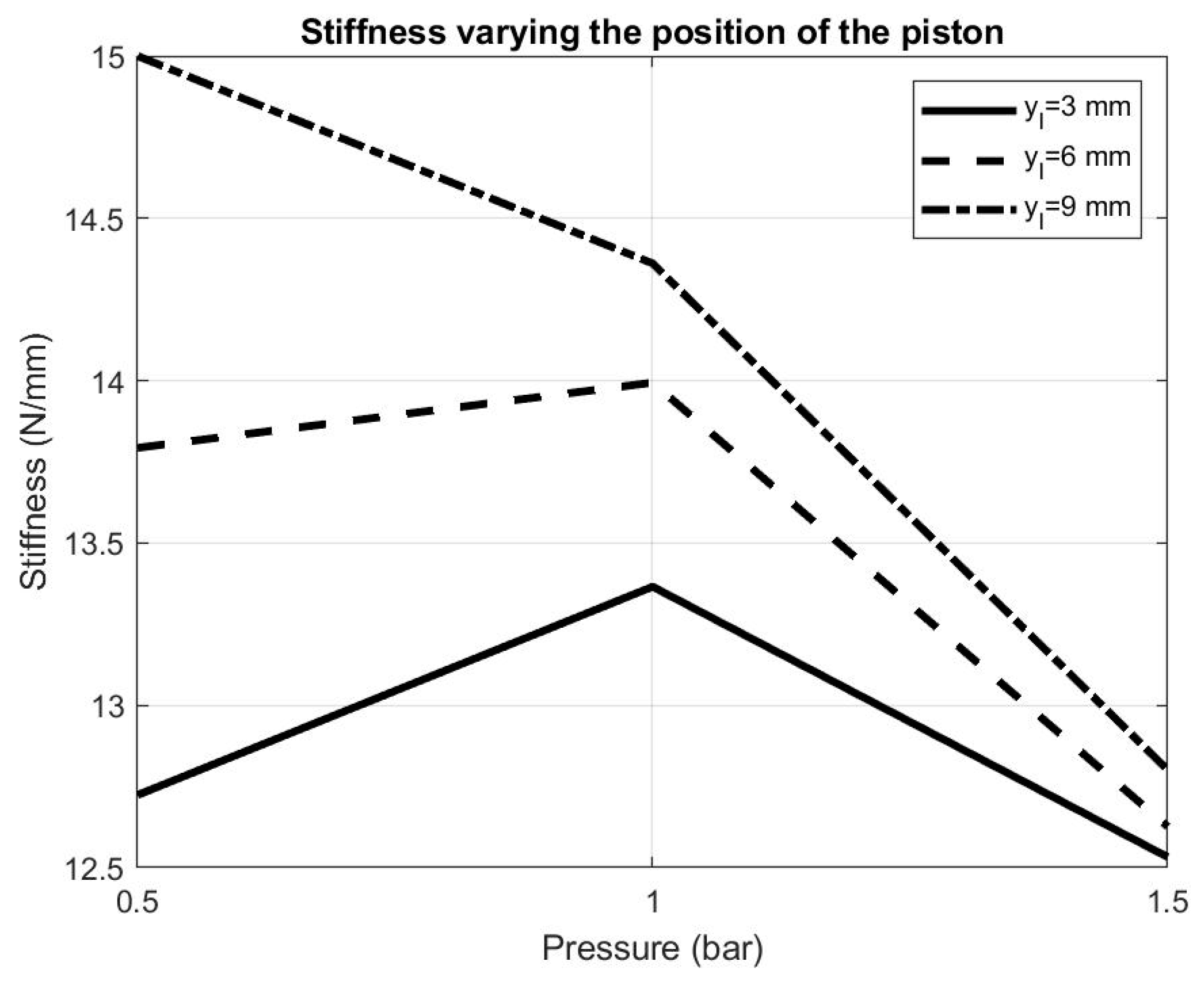
In Figure 10, the results show how the linear stiffness of the whole system varies as a function of the yl displacement. In particular, if the displacement increases (yl = 3 mm, yl = 6 mm, yl = 9 mm in Figure 10) the stiffness will increase its value more for a lower (0.5 bar) then a higher value (1.5 bar) of pressure.
6. Conclusions
In this work, an original variable Remote Center of Compliance (RCC) device obtained from a novel soft pneumatic actuator was studied. The device is equipped with a particular structure that also allows varying its stiffness in the not-actuated directions. The position of the RCC was determined by studying the symmetrical constraints of the device, as performed by past works on RCC, and a simple formulation based on the device characteristics and the operating pressures was proposed. Comparison with FEM analysis demonstrated the effectiveness of this formulation for the pressure range 0.2–1 bar. While keeping in mind the original characteristics of our device, its performance was compared with that of some of the RCC devices described in the literature. Ciblak and Lipkin [27] conducted a FEM simulation of their system, evaluating a stiffness of about 131 N/mm with a lateral displacement of the RCC point of about 5.08 mm. The variable RCC device proposed by Zhao et al. [29] presents a lateral stiffness of the device of 133.3 N/mm, which is able to modify the longitudinal RCC position from 42 to 160 mm. Our proposed device is softer because, in the current configuration, the lateral stiffness can vary between 4 and 15 N/mm. However, a significant increase could be achieved using membranes with a textile reinforcement, which is less subject to the buckling phenomenon. In addition, the regulation range of the RCC position, which currently varies between 125 and 221 mm, can be widened with the use of more performing membranes. Ultimately, the results of this work demonstrate the feasibility of soft RCC devices, highlighting possible new scenarios in the field of soft robotics. In the near future it is planned to create several prototypes, in various configurations, to evaluate their characteristics and verify the effectiveness of the empirical model.
Author Contributions
S.B. and G.G.M. performed the analysis; S.B. performed the simulation and validation. G.G.M. conceived and performed the models of the PATuCCo actuator, managed and supervised the entire work; C.F. conceived the idea to find the RCC of the PATuCCo actuator, managed and supervised the entire work. All authors participated in writing, review and editing of the paper. All authors have read and agreed to the published version of the manuscript.
Funding
This research received no external funding.
Conflicts of Interest
The authors declare no conflict of interest.
References
- Bright, G.; Duebler, C. Design and Implementation of an Intelligent Remote Centre Compliance (IRCC) as a Means of Intelligent Position Feedback for a Construction Robot. In Proceedings of the 16th IAARC/IFAC/IEEE International Symposium on Automation and Robotics in Construction, Madrid, Spain, 22–24 September 1999; pp. 719–723. [Google Scholar]
- Drake, S.H. Using Compliace in Lieu of Sensory Feedback for Automatic Assembly. Ph.D. Thesis, Massachusetts Institute of Technology, Cambridge, MA, USA, September 1977. [Google Scholar]
- Watson, P.C. Instrumented Remote Center Compliance Device. U.S. Patent 4,316,329A, 23 February 1982. [Google Scholar]
- Drake, S.H.; Simunovic, S.N. Compliant Assembly System Device. U.S. Patent 4,155,169A, 22 May 1979. [Google Scholar]
- Nevins, J.L.; Whitney, D.E. Assembly Research. Automatica 1980, 16, 595–613. [Google Scholar] [CrossRef]
- De Fazio, T. Single Stage Remote Center Compliance Device. U.S. Patent 4,414,750A, 15 November 1983. [Google Scholar]
- Whitney, D.E.; De Fazio, T. Transferrable-Center Compliance System. U.S. Patent 4,439,926A, 3 April 1984. [Google Scholar]
- Sorli, M.; Govi, G. Insertion Force Recognition by Modelling and Simulation of Assembly Systems with Accomodators. In IFAC Proceedings Volumes; Elsevier BV: Amsterdam, The Netherlands, 1992; Volume 25, pp. 111–116. [Google Scholar]
- Joo, S.; Miyazaki, F. On the Mechanics of Elastomer Shear Pads for Remote Center Compliance (RCC). Trans. Inst. Syst. Control. Inf. Eng. 1996, 9, 383–391. [Google Scholar] [CrossRef]
- Whitney, D.E.; De Fazio, E.T. Adjustable Remote Center Compliance Device. U.S. Patent 4,477,975A, 23 October 1984. [Google Scholar]
- Sethi, T. Design and Development of Instrumented Remote Centre Compliance. Master’s Thesis, National Institute of Technologyrourkela, Odisha, India, 12 January 2016. [Google Scholar]
- Drake, S.H.; Simunovic, S.N. Compliance Element for Remote Center Compliance Unit. U.S. Patent 4,276,697A, 7 May 1981. [Google Scholar]
- Lee, S. Development of a New Variable Remote Center Compliance (VRCC) With Modified Elastomer Shear Pad (ESP) for Robot Assembly. IEEE Trans. Autom. Sci. Eng. 2005, 2, 193–197. [Google Scholar] [CrossRef]
- Beltran-Hernandez, C.C.; Petit, D.; Ramirez-Alpizar, I.G.; Harada, K. Variable Compliance Control for Robotic Peg-In-Hole Assembly: A Deep-Reinforcement-Learning Approach. Appl. Sci. 2020, 10, 6923. [Google Scholar] [CrossRef]
- Zhang, Y.; Lu, H.; Pham, D.T.; Wang, Y.; Yongquan, Z.; Lim, J.; Su, S. Peg–hole disassembly using active compliance. R. Soc. Open Sci. 2019, 6, 190476. [Google Scholar] [CrossRef] [PubMed] [Green Version]
- Lai, L.-J.; Zhu, Z.-N. Modeling and Analysis of a Compliance Model and Rotational Precision for a Class of Remote Center Compliance Mechanisms. Appl. Sci. 2016, 6, 388. [Google Scholar] [CrossRef] [Green Version]
- Parks, P.A.; Light, N.A.; Bathurst, S.P.; Higginson, J.A.; Bibl, A. Mass Transfer Tool Manipulator Assembly with Remote Center of Compliance. U.S. Patent 10,183,396, 22 January 2019. [Google Scholar]
- Vaschieri, V.; Gadaleta, M.; Bilancia, P.; Berselli, G.; Razzoli, R. Virtual Prototyping of a Flexure-based RCC Device for Automated Assembly. Procedia Manuf. 2017, 11, 380–388. [Google Scholar] [CrossRef]
- Muscolo, G.G.; Fontana, M. A Novel Linear Pneumatic Actuator with Tunable-Compliance Constraint. Int. J. Mech. Control, submitted.
- Jafari, A.; Tsagarakis, N.G.; Caldwell, D.G. A Novel Intrinsically Energy Efficient Actuator with Adjustable Stiffness (AwAS). IEEE/ASME Trans. Mechatron. 2013, 18, 355–365. [Google Scholar] [CrossRef]
- Van Ham, R.; VanderBorght, B.; Van Damme, M.; Verrelst, B.; Lefeber, D. MACCEPA, the mechanically adjustable compliance and controllable equilibrium position actuator: Design and implementation in a biped robot. Robot. Auton. Syst. 2007, 55, 761–768. [Google Scholar] [CrossRef]
- Kim, B.-S.; Song, J.-B. Design and Control of a Variable Stiffness Actuator Based on Adjustable Moment Arm. IEEE Trans. Robot. 2012, 28, 1145–1151. [Google Scholar] [CrossRef]
- Franchi, V.; Di Rito, G.; Galatolo, R.; Cannella, F.; Caldwell, D.; Muscolo, G.G. Multibody Analysis and Design of an Electromechanical System Simulating Hyperelastic Membranes. In Computational Methods in Applied Sciences; Springer Science and Business Media LLC: Berlin/Heidelberg, Germany, 2019; Volume 53, pp. 115–122. [Google Scholar]
- Franchi, V.; Di Rito, G.; Galatolo, R.; Cannella, F.; Caldwell, D.; Muscolo, G.G. Modelling and Control Design of a Novel Robotic Membrane. Int. J. Mech. Control 2019, 20, 113–122. [Google Scholar]
- Muscolo, G.G.; Moretti, G.; Cannata, G. SUAS: A Novel Soft Underwater Artificial Skin with Capacitive Transducers and Hyperelastic Membrane. Robotica 2018, 37, 756–777. [Google Scholar] [CrossRef]
- Bolignari, M.; Fontana, M. Design and experimental characterization of a high performance hydrostatic transmission for robot actuation. Meccanica 2020, 1–11. [Google Scholar] [CrossRef]
- Ciblak, N.; Lipkin, H. Design and Analysis of Remote Center of Compliance Structures. J. Robot. Syst. 2003, 20, 415–427. [Google Scholar] [CrossRef]
- Ogden, R. Elastic Deformations of Rubberlike Solids. In Mechanics of Solids; Elsevier BV: Amsterdam, The Netherlands, 1982; pp. 499–537. [Google Scholar]
- Zhao, F.; Wu, P.S. VRCC: A variable remote center compliance device. Mechatronics 1998, 8, 657–672. [Google Scholar] [CrossRef]
Figure 1.
Simple sketch of the section of a truncated-conical arrangement.

Figure 2.
Movement of the system when a force F is applied to E.

Figure 3.
The linear Pneumatic Actuator system with Tunable-Compliance Constraint (PATuCCo).

Figure 4.
Device in the initial condition (dotted line) and after a longitudinal displacement yL (continuous line).
Figure 4.
Device in the initial condition (dotted line) and after a longitudinal displacement yL (continuous line).

Figure 5.
(a) CAD model of the linear pneumatic actuator used for the FEM analysis; (b) application points of force when yL = 0 and Q = Q0; (c) constraints used in the FEM model of the membrane.
Figure 5.
(a) CAD model of the linear pneumatic actuator used for the FEM analysis; (b) application points of force when yL = 0 and Q = Q0; (c) constraints used in the FEM model of the membrane.

Figure 6.
Comparison between Formulation (2) (mod) and the FEM simulation (sim) by modifying the distance Q from P and using a pressure range from 0.2 to 1 bar.
Figure 6.
Comparison between Formulation (2) (mod) and the FEM simulation (sim) by modifying the distance Q from P and using a pressure range from 0.2 to 1 bar.

Figure 7.
Comparison between Formulation (2) (mod) and the FEM simulation (sim), modifying the distance Q from P and considering a pressure range from 0.5 to 2 bar.
Figure 7.
Comparison between Formulation (2) (mod) and the FEM simulation (sim), modifying the distance Q from P and considering a pressure range from 0.5 to 2 bar.

Figure 8.
Linear stiffness as a function of the pressure (FX = 5 N).

Figure 9.
Stiffness of each point of application of the force along the Y axis and rotation angle around the Z axis if the force FX = 5 N is applied.
Figure 9.
Stiffness of each point of application of the force along the Y axis and rotation angle around the Z axis if the force FX = 5 N is applied.

Figure 10.
Stiffness varying the position of the piston (yl = 3 mm, yl = 6 mm, yl = 9 mm) for the pressure range 0.5–1.5 bar (FX = 15 N).
Figure 10.
Stiffness varying the position of the piston (yl = 3 mm, yl = 6 mm, yl = 9 mm) for the pressure range 0.5–1.5 bar (FX = 15 N).

Publisher’s Note: MDPI stays neutral with regard to jurisdictional claims in published maps and institutional affiliations. |
© 2020 by the authors. Licensee MDPI, Basel, Switzerland. This article is an open access article distributed under the terms and conditions of the Creative Commons Attribution (CC BY) license (http://creativecommons.org/licenses/by/4.0/).
Share and Cite
MDPI and ACS Style
Bottero, S.; Muscolo, G.G.; Ferraresi, C. A New Soft RCC Device with Pneumatic Regulation. Robotics 2020, 9, 98. https://0-doi-org.brum.beds.ac.uk/10.3390/robotics9040098
AMA Style
Bottero S, Muscolo GG, Ferraresi C. A New Soft RCC Device with Pneumatic Regulation. Robotics. 2020; 9(4):98. https://0-doi-org.brum.beds.ac.uk/10.3390/robotics9040098
Chicago/Turabian StyleBottero, Stefano, Giovanni Gerardo Muscolo, and Carlo Ferraresi. 2020. "A New Soft RCC Device with Pneumatic Regulation" Robotics 9, no. 4: 98. https://0-doi-org.brum.beds.ac.uk/10.3390/robotics9040098
Note that from the first issue of 2016, this journal uses article numbers instead of page numbers. See further details here.