
Extracting 3D Indoor Maps with Any Shape Accurately Using Building Information Modeling Data


Abstract
:1. Introduction
2. Literature Review
2.1. Floor-Level Indoor Map Generation Using BIM Data
2.1.1. Grid-Based Map
2.1.2. Topological Map
2.2. Cross-Floor Indoor Path Generation Using BIM Data
3. Materials and Methods
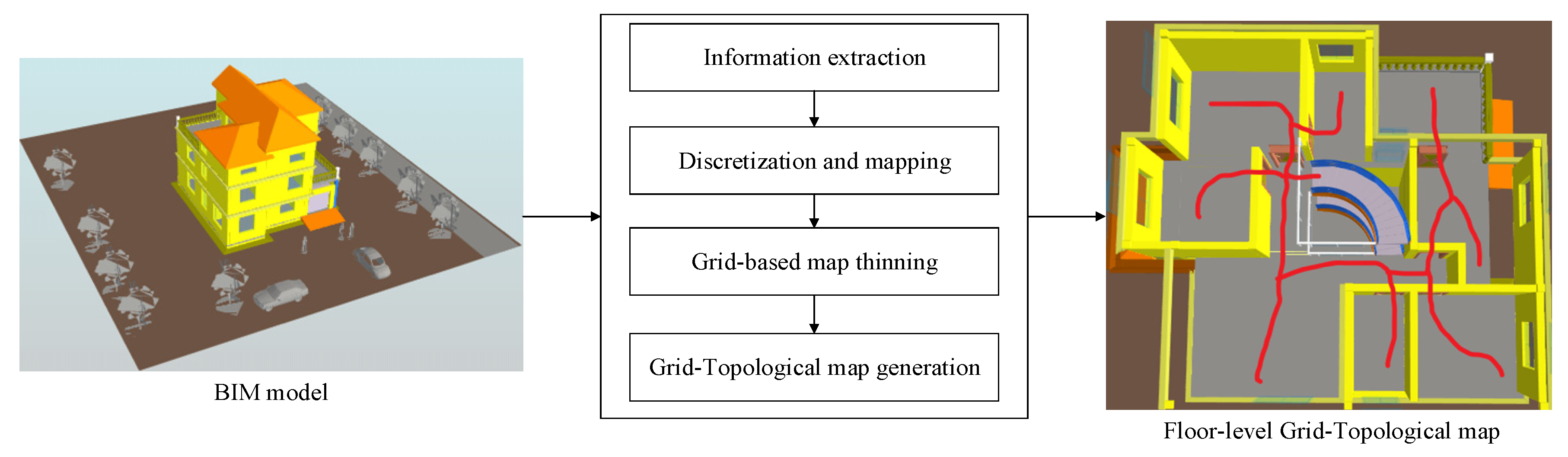
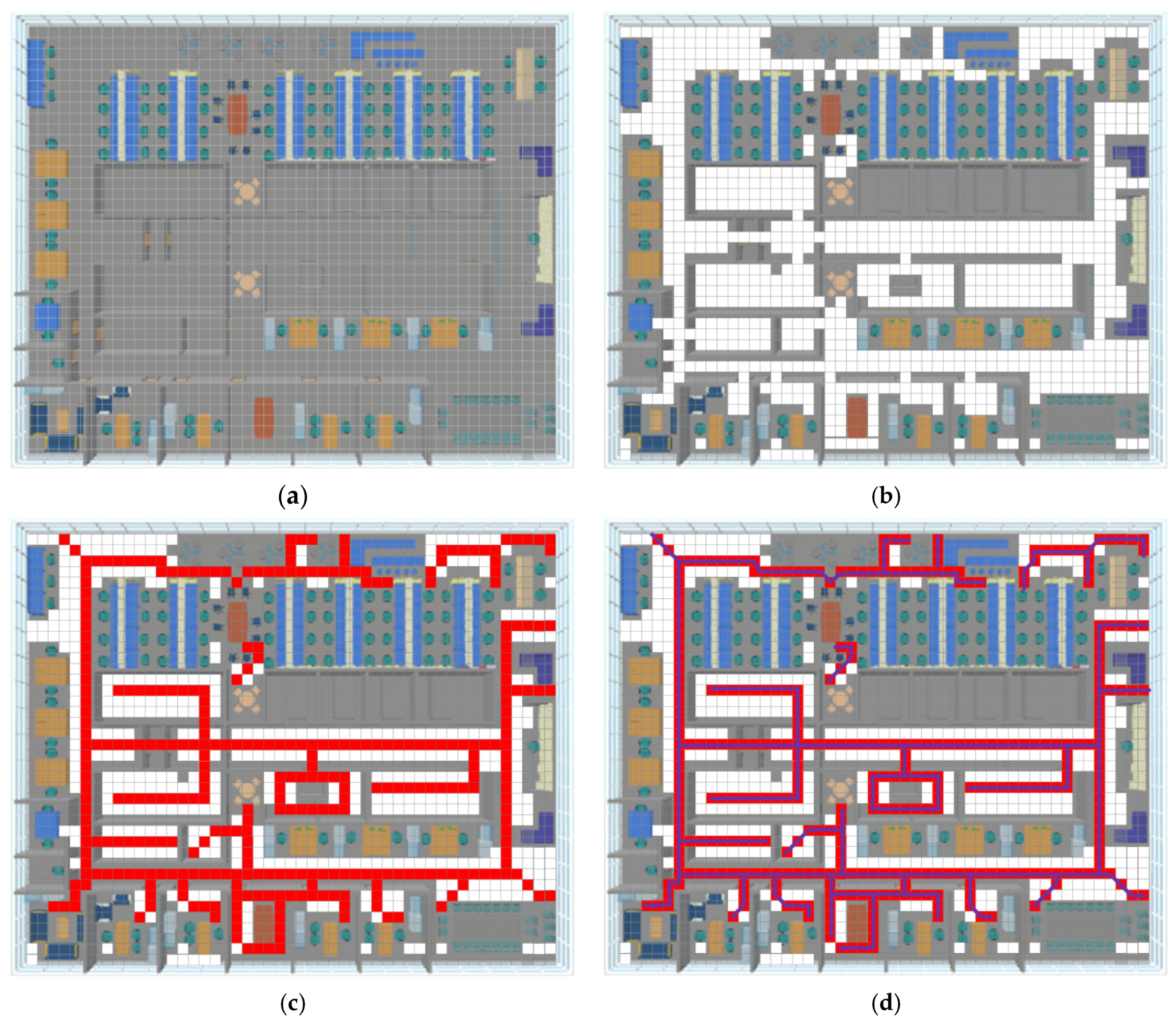
3.1. Floor-Level Indoor Map
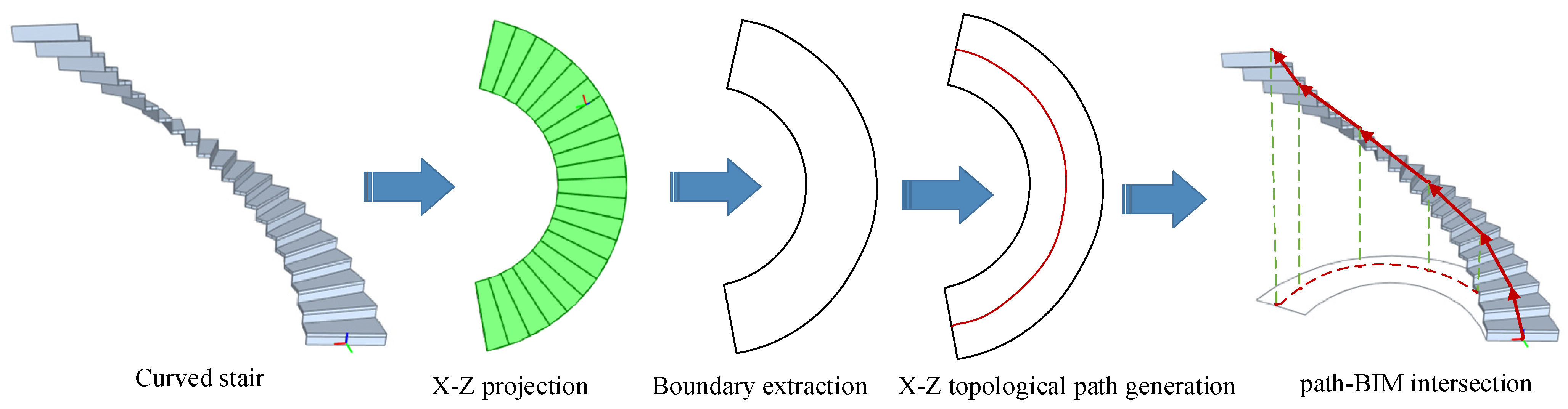
3.2. Cross-Floor Indoor Path Generation
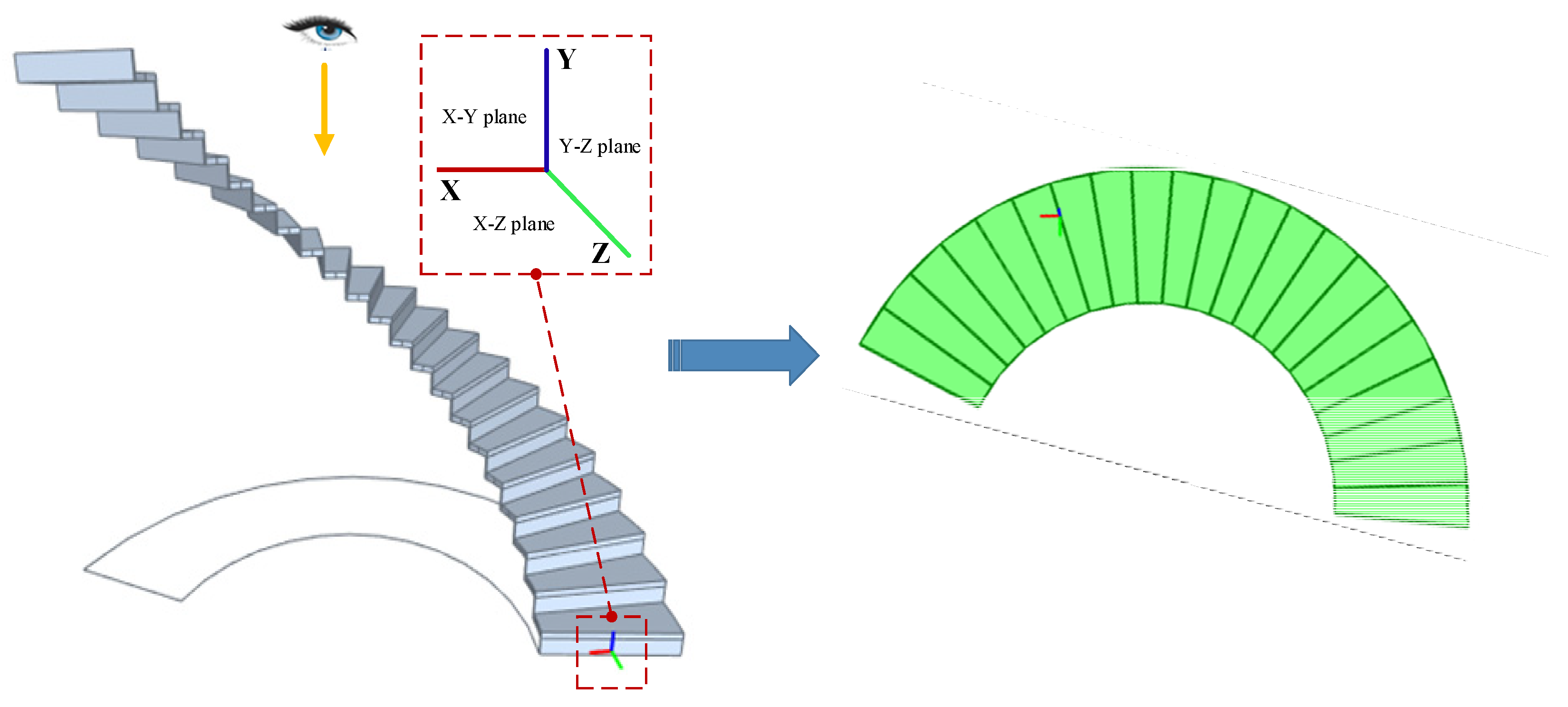
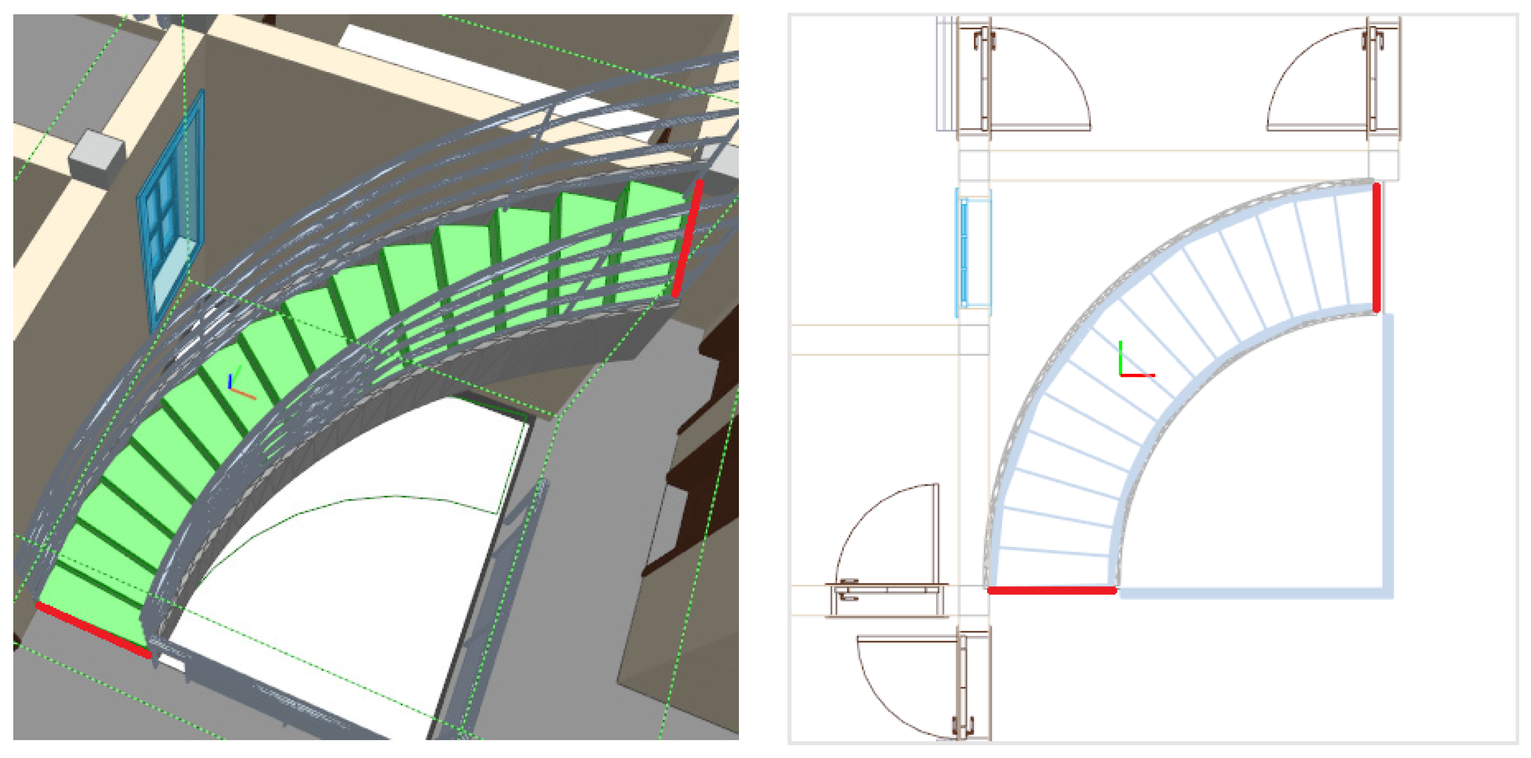
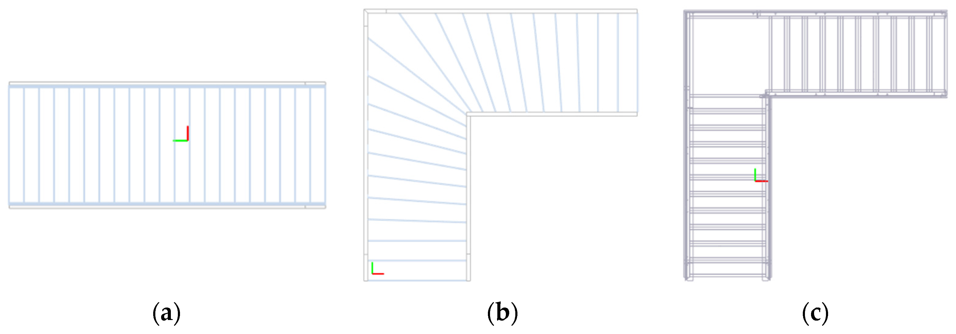
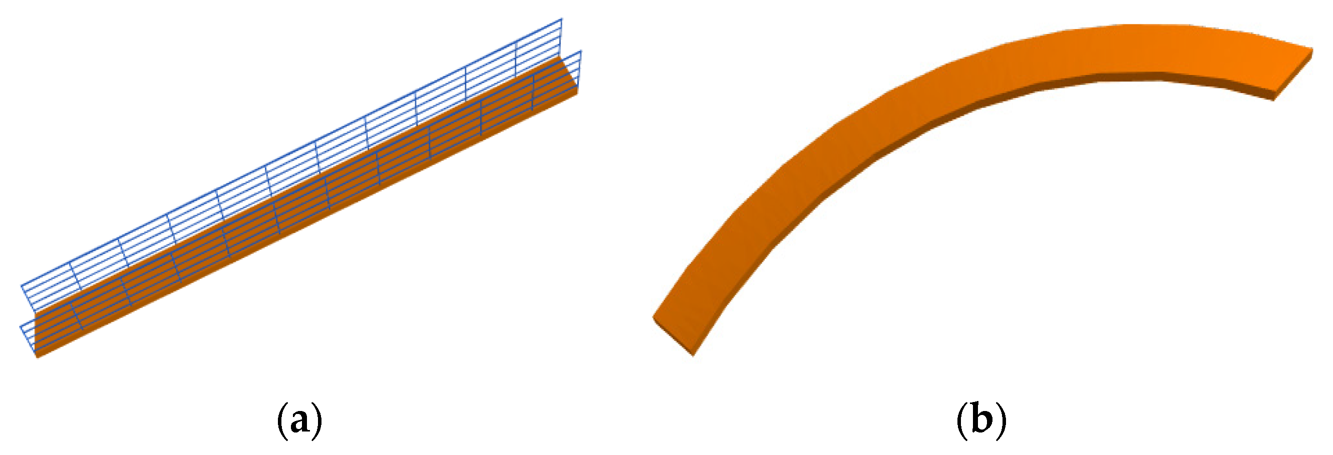
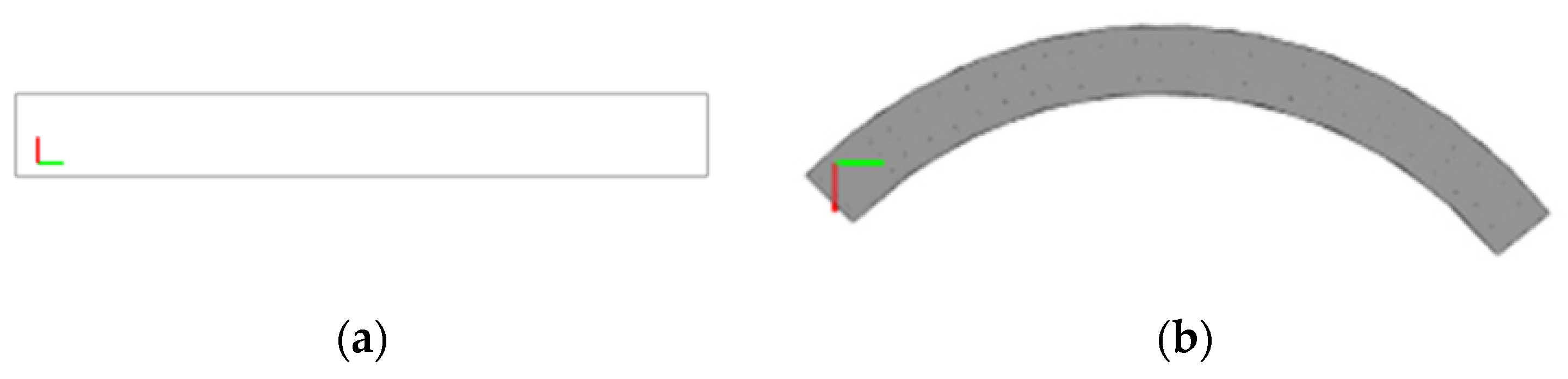
3.2.1. X-Z Projection
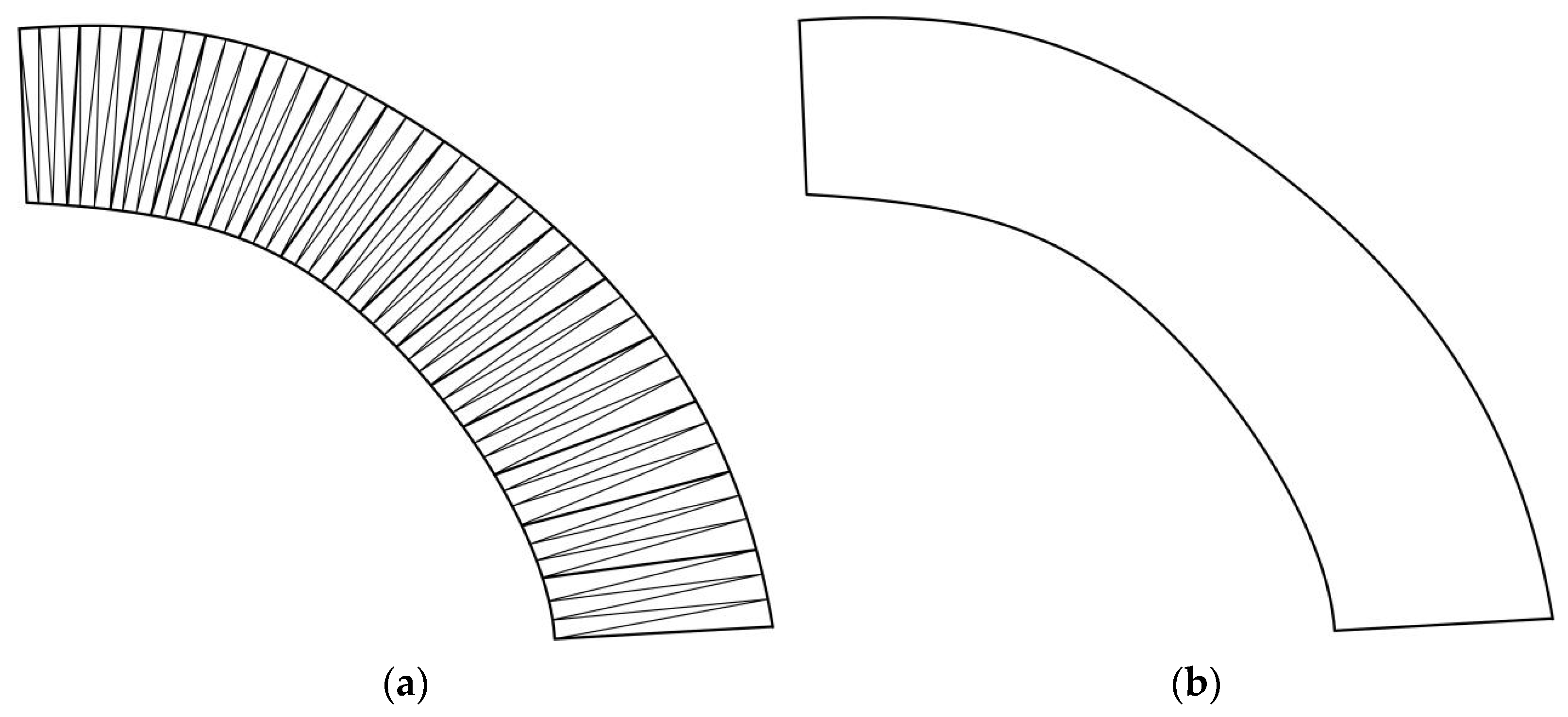
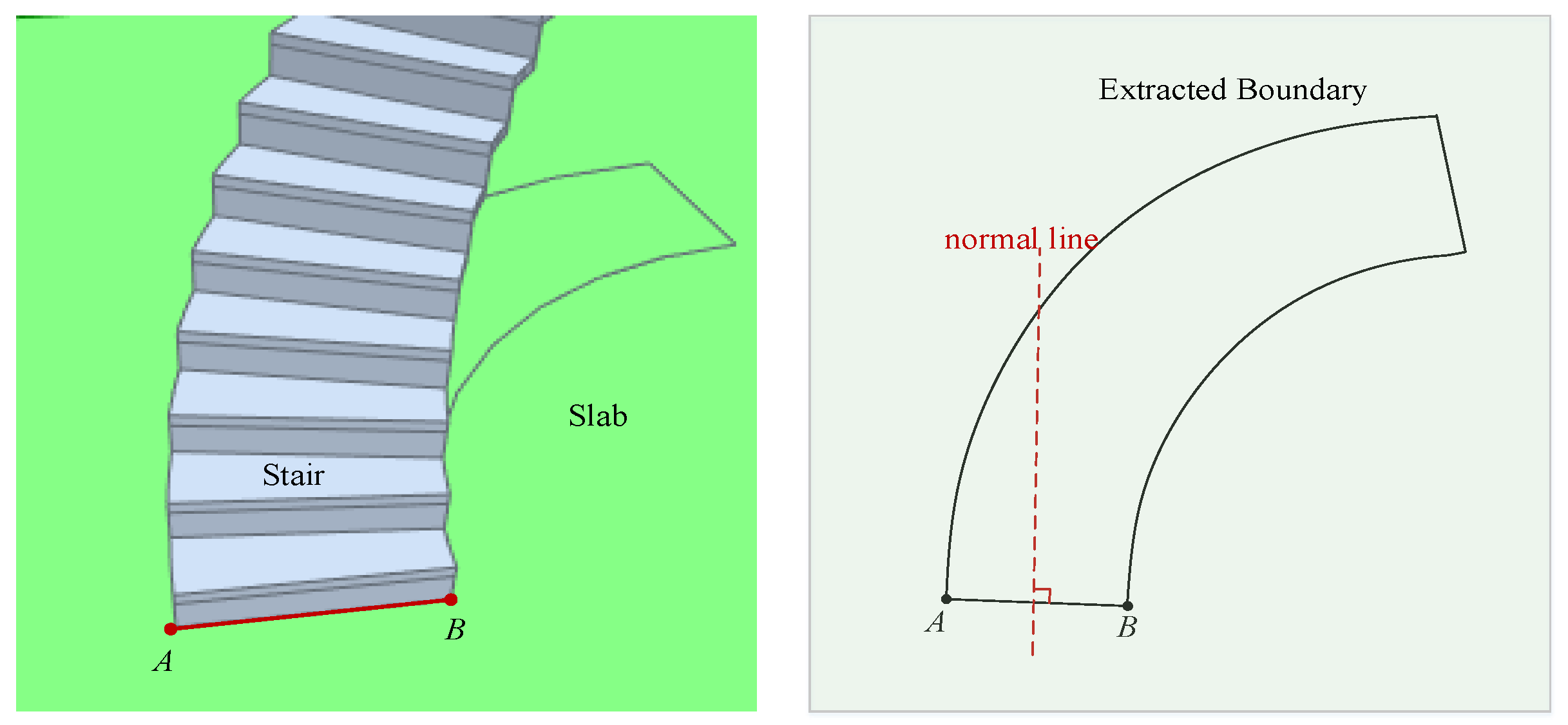
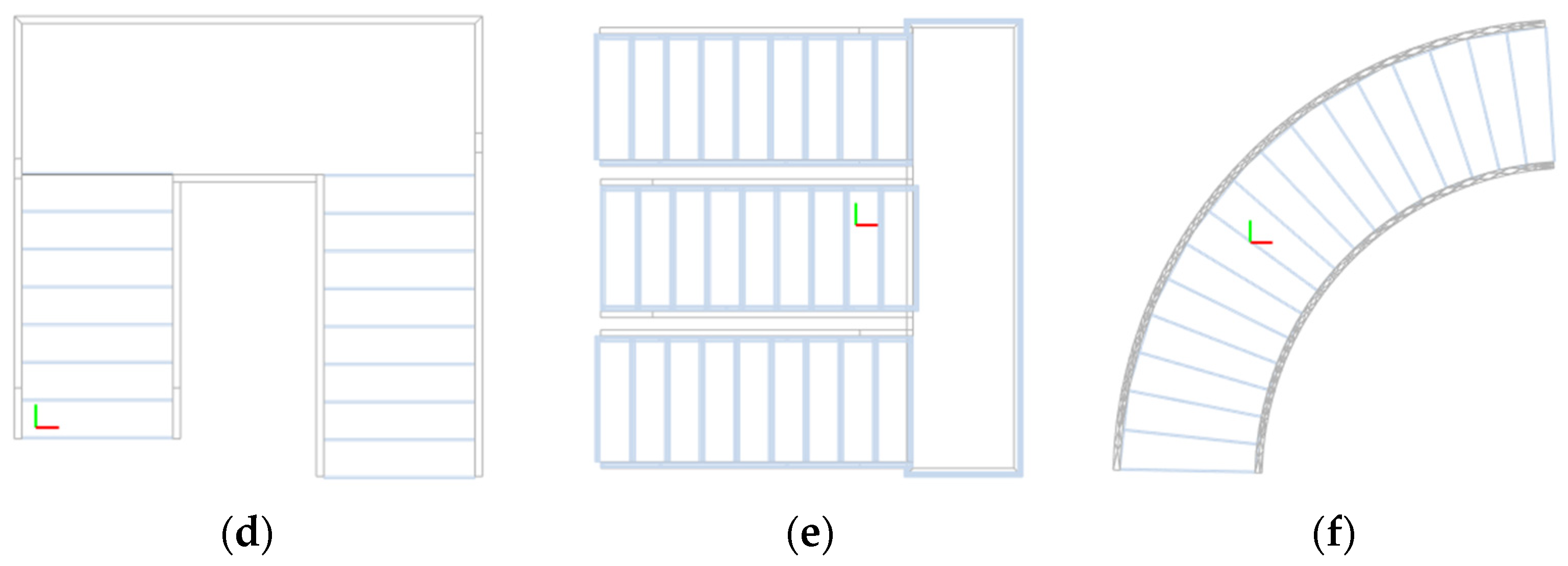
3.2.2. Boundary Extraction
| Algorithm 1. Boundary extraction for the X-Z projection |
| Input: Cross-floor element C |
| Output: Boundary b |
| 1: function BoundaryExtraction(C) |
| 2: Set 3D coordinate with x-, y- and z-axis for the cross-floor elements C. |
| 3: Obtain the X-Z projection CT by setting y = 0 in the 3D coordinate system. |
| 4: L = []. |
| 5: L = the projected intersection lines between slabs and cross-floor elements. |
| 6: ei = any line in L. |
| 7: Save the original coordinate of edge ei, ei = {p11, p12}. |
| 8: b = ei. |
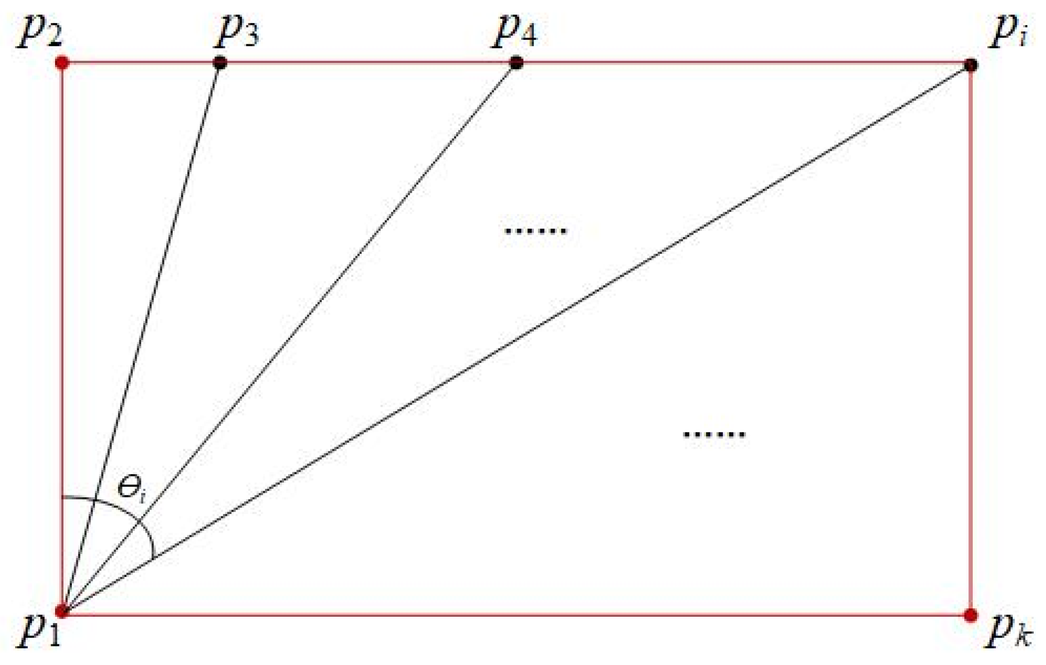
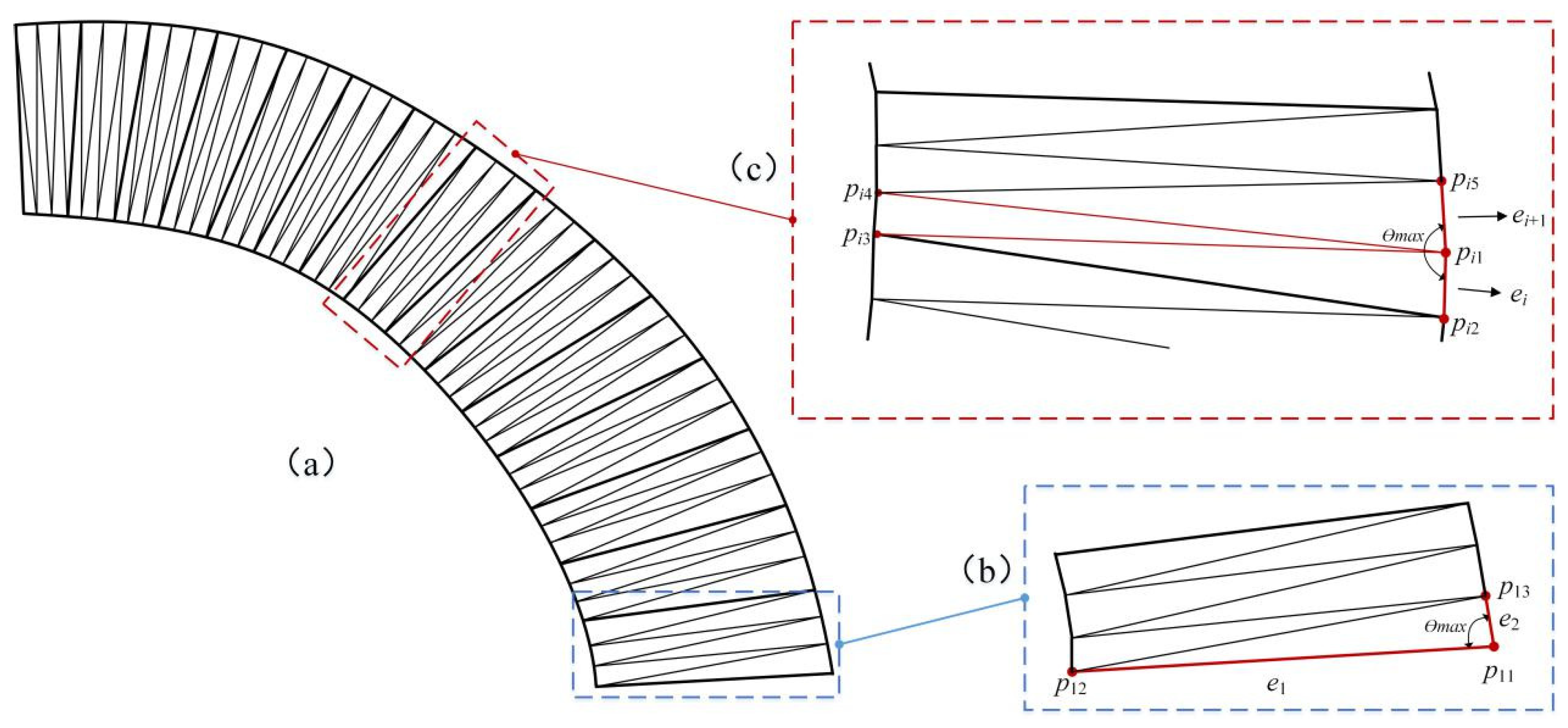
| 9: ei = pi1pi2. |
| 10: Define the other endpoints of the vectors as pi3, pi4, …, pik. |
| 11: Compute the turning angles between vector pi1pi2 and the other vectors respectively using Equation (3) and Equation (4). |
| 12: Extract vector pi1pij that has the maximum turning angle θj with vector pi1pi2. |
| 13: ei+1 = pi1pij. |
| 14: b = b ∪ {ei+1}. |
| 15: if pij = p12 |
| 16: ei = ei+1 and rerun line 9 to line 14. |
| 17: else end |
| 18: return boundary b. |
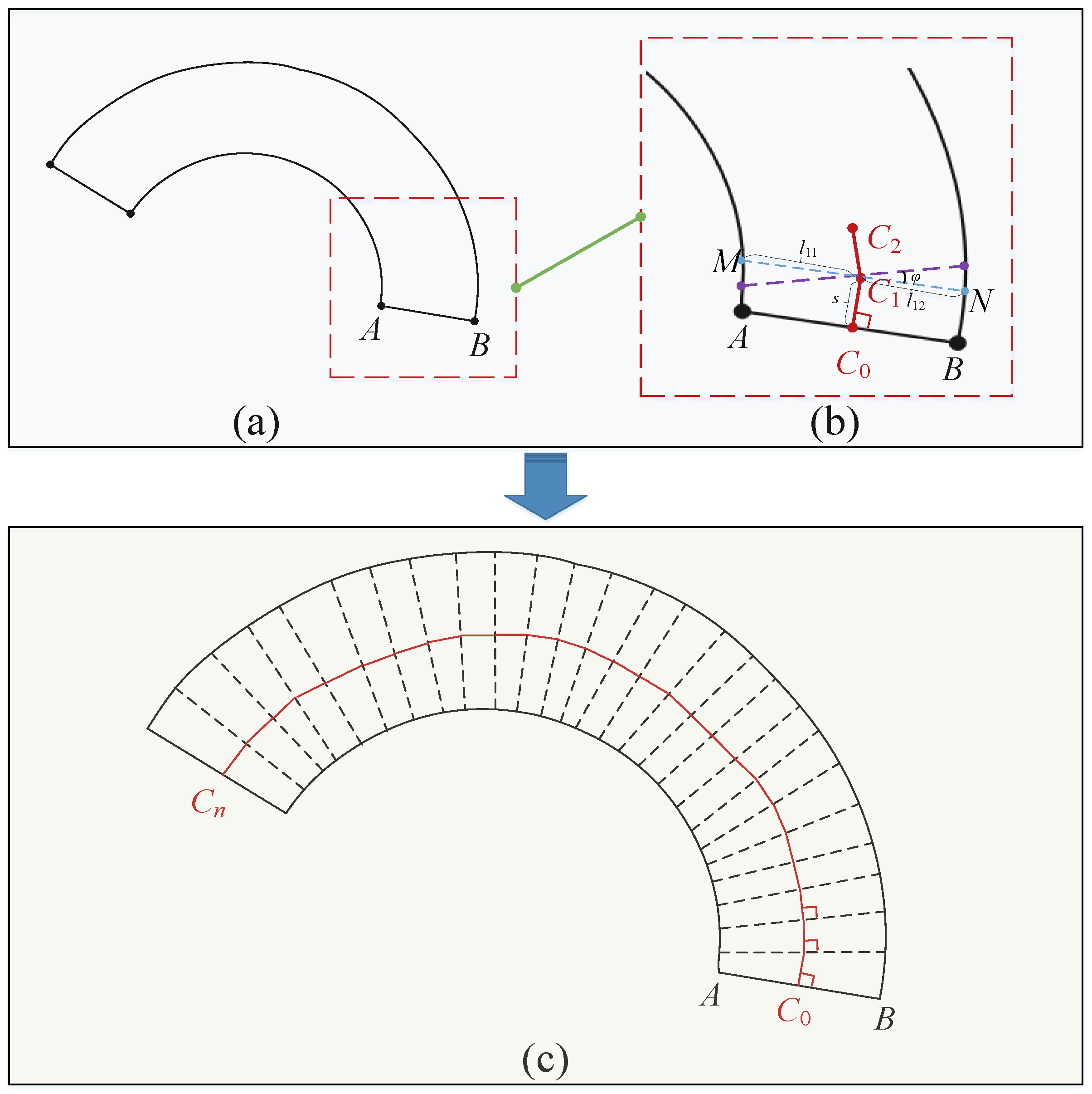
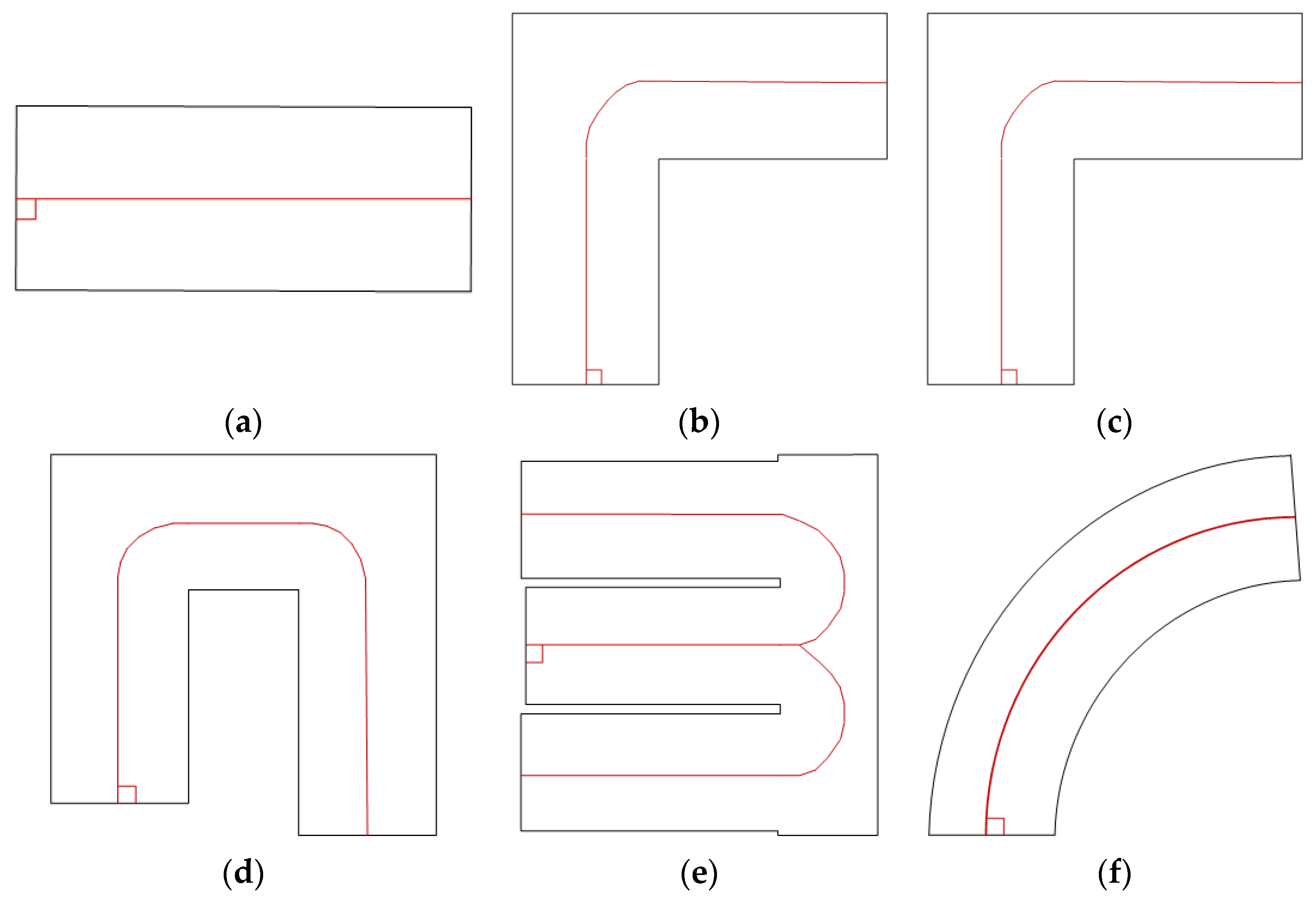
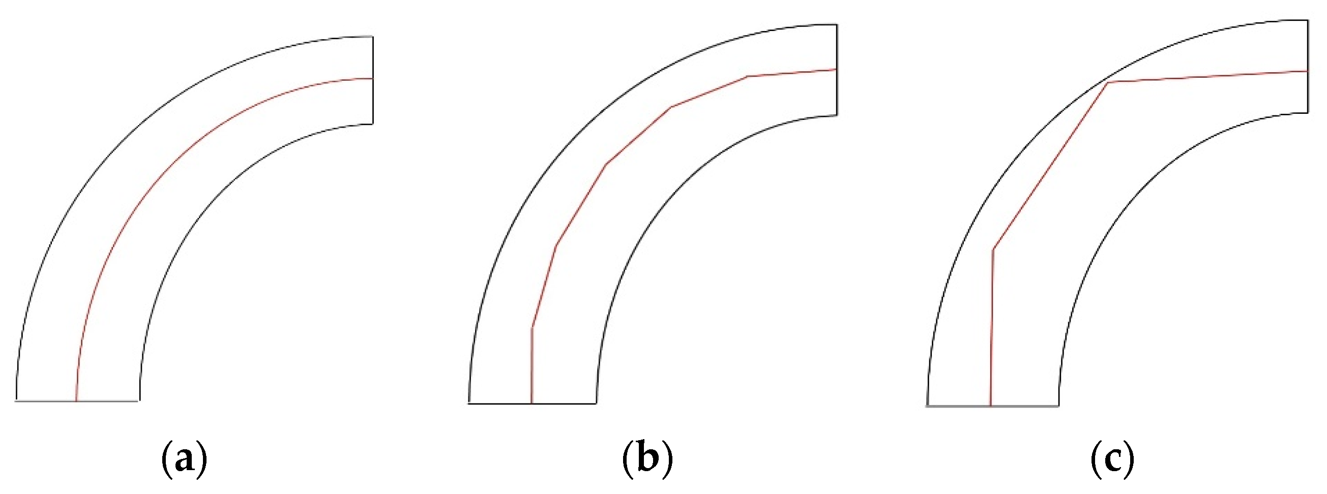
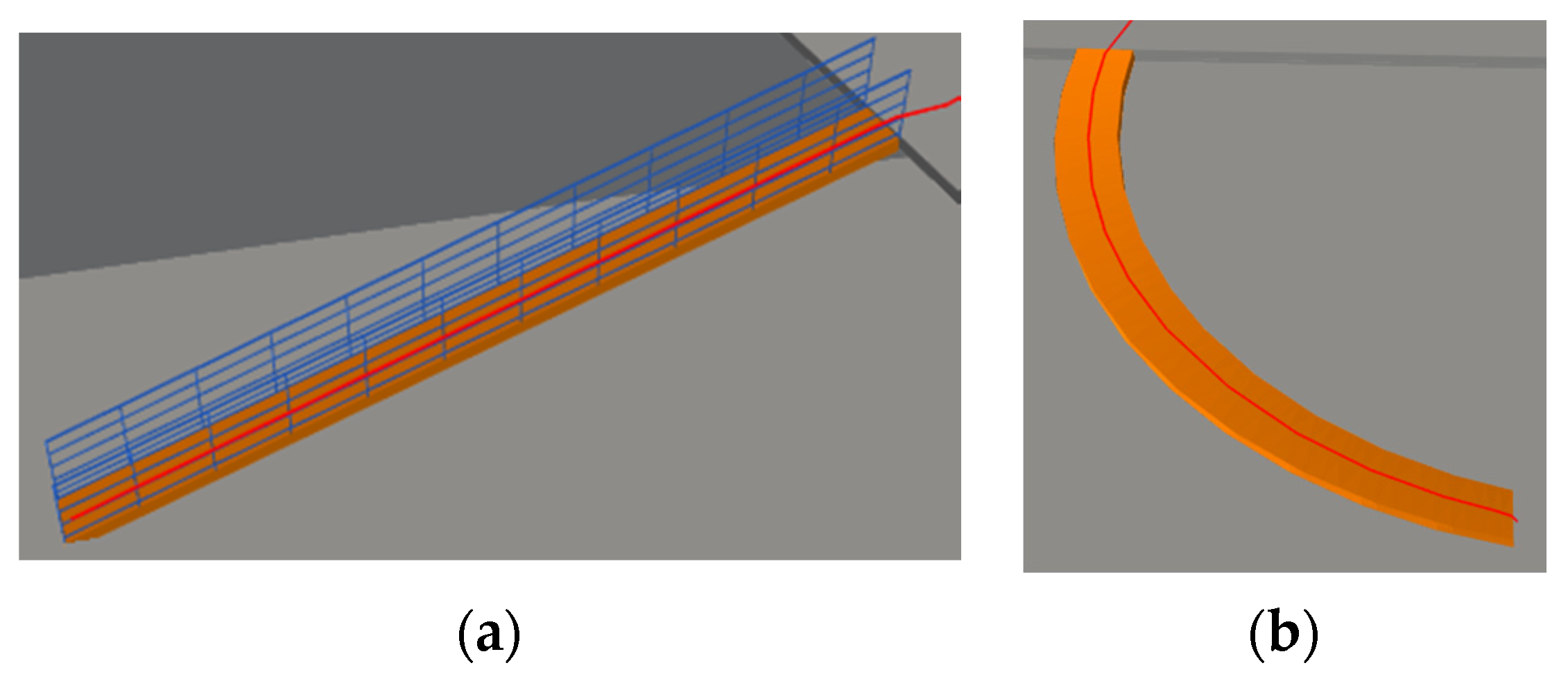
3.2.3. The X-Z Topological Path Generation
- Step 1. Making a vertical line.
- Step 2. Selecting reference line.
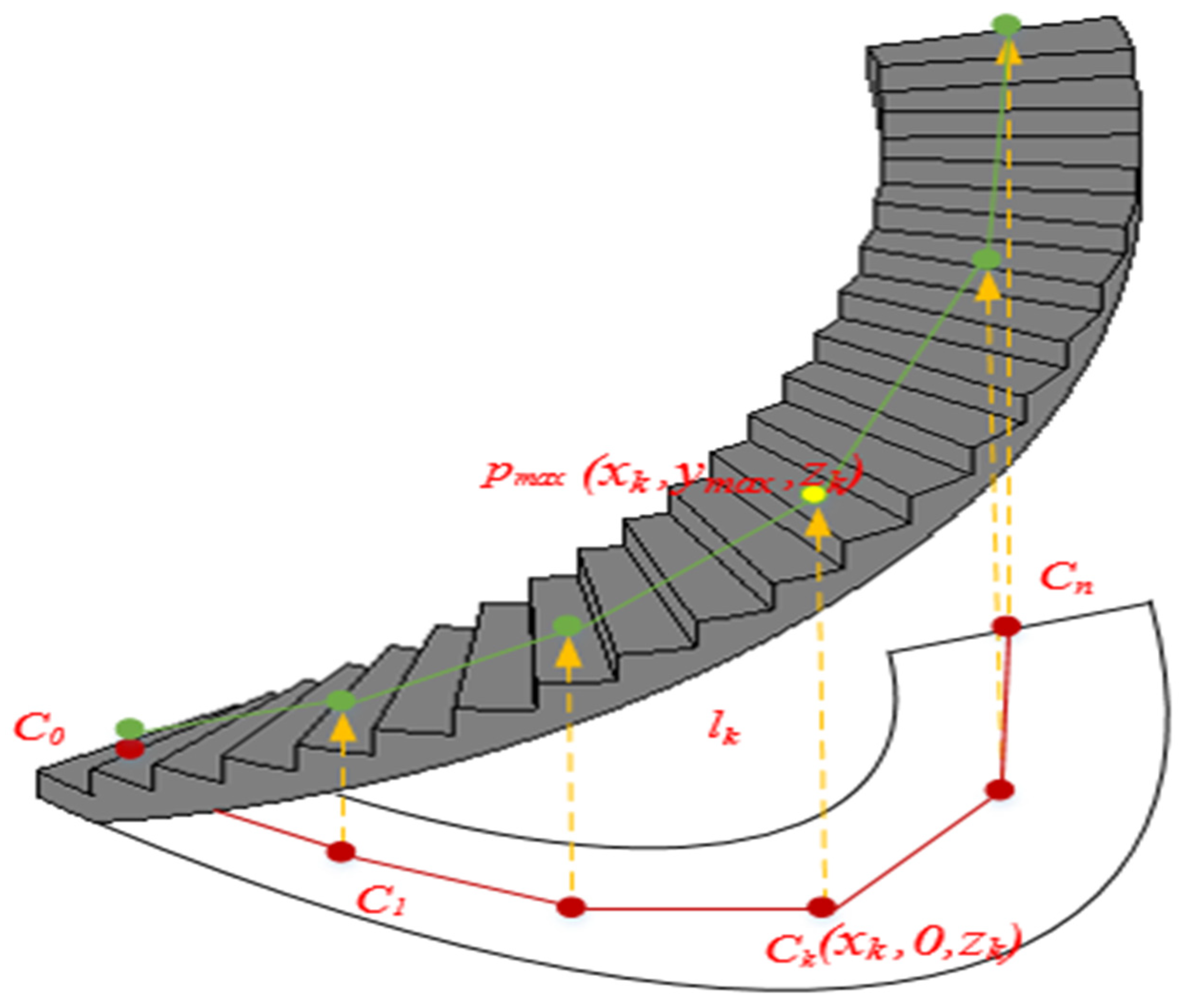
3.2.4. Path-BIM Intersection
| Algorithm 2. 3D topological path generation for the cross-floor elements |
| Input: The Boundary b of the cross-floor element C |
| Output: 3D topological path P |
| 1: function PathGenerationUsingCrossFloorElement(C) |
| 2: D = []. |
| 3: D = the start lines. |
| 4: Select any start line from the collection D. |
| 5: Define the start line AB as the reference line. |
| 6: Make the normal line of the reference line and select the direction that the normal line intersects with boundary b as the path direction. |
| 7: for the midpoint of AB, Ci, do |
| 8: Make a vertical line CiCi+1 with length s and CiCi+1 ⊥ AB. |
| 9: for the endpoint Ci+1, do |
| 10: Make a line MN through the endpoint Ci+1, and MN//AB. |
| 11: for line MN, do |
| 12: Rotate line MN with angle φ. |
| 13: Select the next reference line using Equations (5)–(7). |
| 14: Rerun line 6 to line 13 until line CiCi+1 intersects with the boundary b or the generated path. |
| 15: for any start line in the collection D that does not intersect with the generated path, do. |
| 16: Rerun line 5 to line 14. |
| 17: Get the X-Z topological path by collecting the generated short vertical line. |
| 18: Get a 3D topological path by intersecting the X-Z topological path with BIM. |
| 19: return 3D topological path P. |
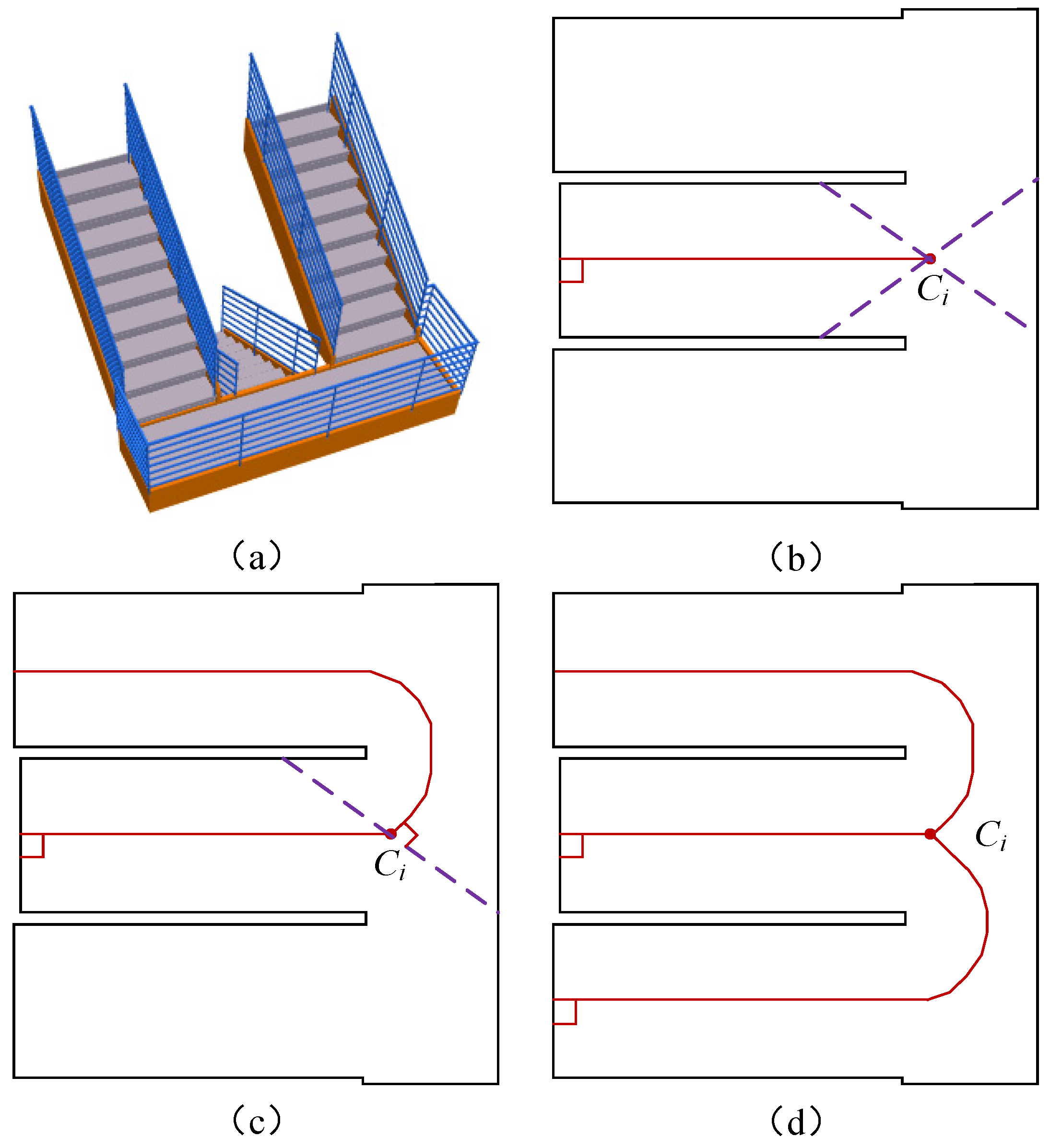
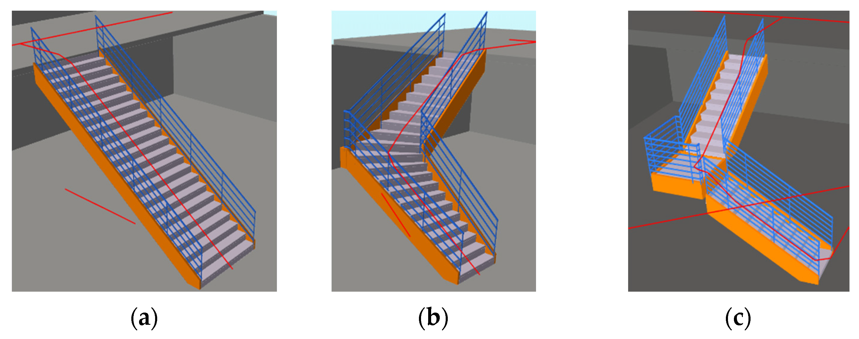
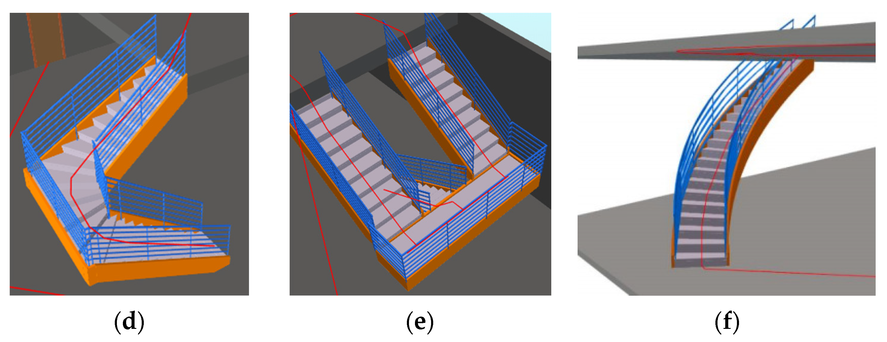
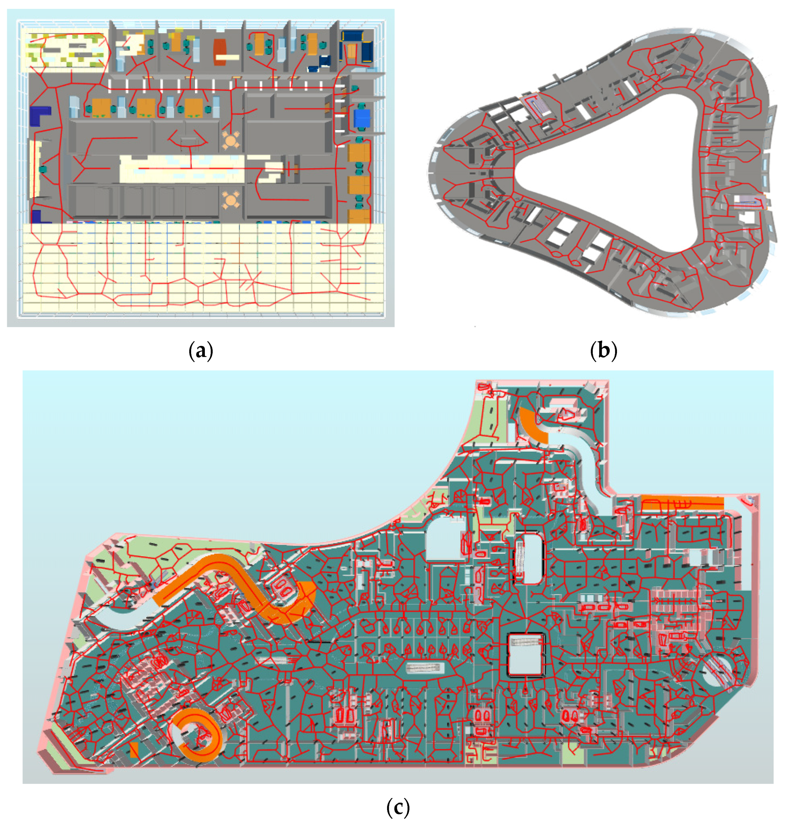
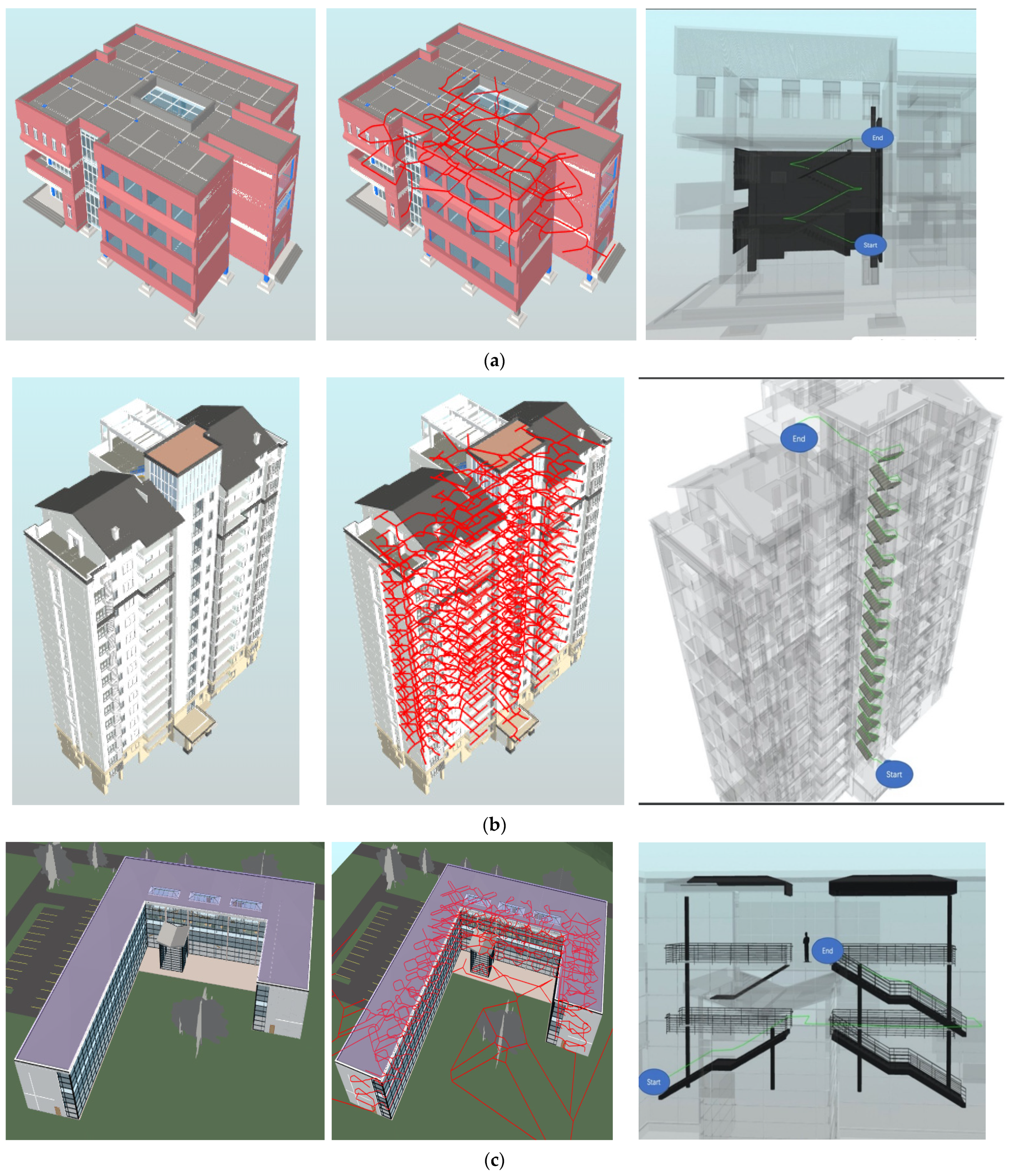
4. Empirical Studies
4.1. Cross-Floor Indoor Map
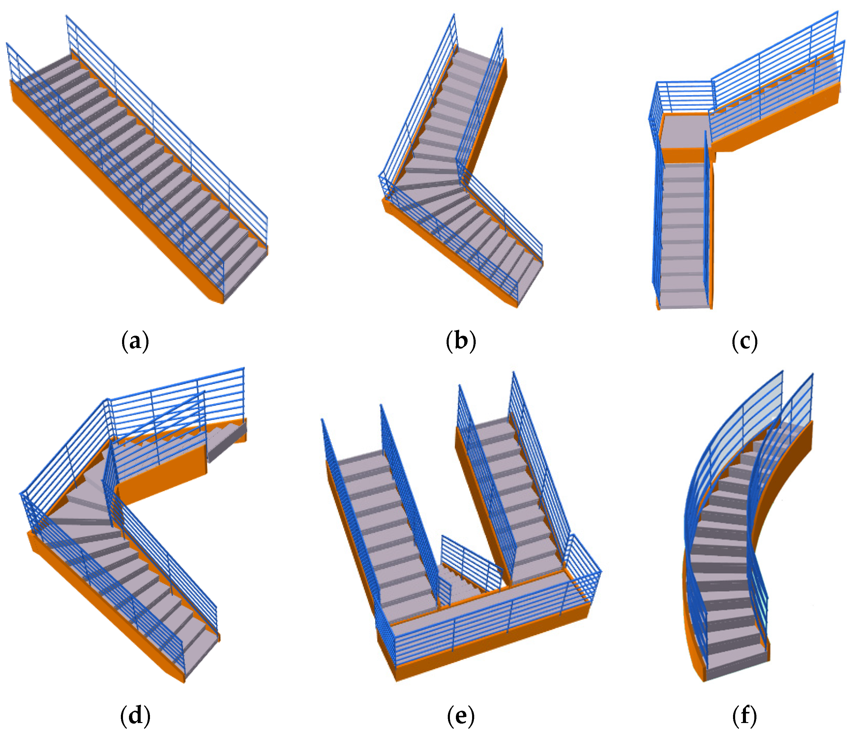
- (1)
- Stairs
- (2)
- Ramps
4.2. Multi-Floor Indoor Map Evaluation
5. Results and Discussion
6. Conclusions
Author Contributions
Funding
Institutional Review Board Statement
Informed Consent Statement
Conflicts of Interest
References
- Liu, J.; Luo, J.; Hou, J.; Wen, D.; Feng, G.; Zhang, X. A BIM Based Hybrid 3D Indoor Map Model for Indoor Positioning and Navigation. Int. J. Geo-Inf. 2020, 9, 747. [Google Scholar] [CrossRef]
- Zhou, X.; Xie, Q.; Guo, M.; Zhao, J.; Wang, J. Accurate and Efficient Indoor Pathfinding Based on Building Information Modelling Data. IEEE Trans. Ind. Inform. 2020, 16, 7459–7468. [Google Scholar] [CrossRef]
- Ji, J.; Ma, Z.; He, J.; Xu, Y.; Liu, Z. Research on Risk Evaluation and Dynamic Escape Path Planning Algorithm Based on Real-Time Spread of Ship Comprehensive Fire. J. Mar. Sci. Eng. 2020, 8, 602. [Google Scholar] [CrossRef]
- Chen, A.; Huang, T. Toward BIM-enabled decision making for in-building response missions. IEEE Trans. Intell. Transp. Syst. 2015, 16, 2765–2773. [Google Scholar] [CrossRef]
- Hassannayebi, E.; Memarpour, M.; Mardani, S.; Shakibayifar, M.; Bakhshayeshi, I.; Espahbod, S. A hybrid simulation model of passenger emergency evacuation under disruption scenarios: A case study of a large transfer railway station. J. Simul. 2019, 14, 204–228. [Google Scholar] [CrossRef]
- Lin, Y.H.; Liu, Y.S.; Gao, G.; Han, X.G.; Lai, C.Y.; Gu, M. The IFC-based path planning for 3D indoor spaces. Adv. Eng. Inform. 2013, 27, 189–205. [Google Scholar] [CrossRef] [Green Version]
- Han, T.; Almeida, J.S.; da Silva, S.P.P.; Honório Filho, P.; de Oliveira Rodrigues, A.W.; de Albuquerque, V.H.C.; Reboucas Filho, P.P. An effective approach to unmanned aerial vehicle navigation using visual topological map in outdoor and indoor environments. Comput. Commun. 2019, 150, 696–702. [Google Scholar] [CrossRef]
- Lin, W.Y.; Lin, H.P. Intelligent generation of indoor topology (i-GIT) for human indoor pathfinding based on IFC models and 3D GIS technology. Autom. Constr. 2018, 94, 340–359. [Google Scholar] [CrossRef]
- Zhou, X.; Zhao, J.; Wang, J.; Huang, X.; Li, X.; Guo, M.; Xie, P. Parallel computing-based online geometry triangulation for building information modeling utilizing big data. Autom. Constr. 2019, 107, 102942. [Google Scholar] [CrossRef]
- Cheng, B.; Li, J.; Tam, V.W.Y.; Yang, M.; Chen, D. A BIM-LCA Approach for Estimating the Greenhouse Gas Emissions of Large-Scale Public Buildings: A Case Study. Sustainability 2020, 12, 685. [Google Scholar] [CrossRef] [Green Version]
- Pang, Y.; Zhou, L.; Lin, B.; Lv, G.; Zhang, C. Generation of navigation networks for corridor spaces based on indoor visibility map. Int. J. Geogr. Inf. Sci. 2020, 34, 177–201. [Google Scholar] [CrossRef]
- Fernández-Caramés, C.; Serrano, F.J.; Moreno, V.; Curto, B.; Rodríguez-Aragón, J.F.; Alves, R. A real-time indoor localization approach integrated with a Geographic Information System (GIS). Robot. Auton. Syst. 2016, 75, 475–489. [Google Scholar] [CrossRef]
- Afyouni, I.; Ray, C.; Claramunt, C. Spatial models for context-aware indoor navigation systems: A survey. J. Spat. Inf. Sci. 2012, 4, 85–123. [Google Scholar] [CrossRef] [Green Version]
- Hart, P.E.; Nilsson, N.J.; Raphael, B. A formal basis for the heuristic determination of minimum cost paths. IEEE Trans. Syst. Sci. Cybern. 1968, 4, 100–107. [Google Scholar] [CrossRef]
- Lee, Y.C.; Park, S. Localization method for mobile robots moving on stairs in multi-floor environments. In Proceedings of the 2014 IEEE International Conference on Systems, Man, and Cybernetics (SMC), San Diego, CA, USA, 5–8 October 2014. [Google Scholar] [CrossRef]
- Babu, V.M.; Krishna, U.V.; Shahensha, S.K. An autonomous path finding robot using Q-learning. In Proceedings of the 2016 10th International Conference on Intelligent Systems and Control (ISCO), Coimbatore, India, 7–8 January 2016. [Google Scholar] [CrossRef]
- Kaleci, B.; Senler, C.M.; Parlaktuna, O.; Gürel, U. Constructing Topological Map from Metric Map Using Spectral Clustering. In Proceedings of the 2015 IEEE 27th International Conference on Tools with Artificial Intelligence (ICTAI), Vietri sul Mare, Italy, 9–11 November 2015; pp. 139–145. [Google Scholar] [CrossRef]
- Fu, C.; Huang, H.; Weibel, R. Adaptive simplification of GPS trajectories with geographic context—A quadtree-based approach. Int. J. Geogr. Inf. Sci. 2020, 35, 661–688. [Google Scholar] [CrossRef]
- Ang, C.H.; Samet, H. Node distribution in a PR quadtree. In Symposium on Large Spatial Databases; Springer: Berlin/Heidelberg, Germany, 1989; Volume 409, pp. 233–252. [Google Scholar] [CrossRef] [Green Version]
- Eppstein, D.; Goodrich, M.T.; Sun, J.Z. The skip quadtree: A simple dynamic data structure for multidimensional data. In Proceedings of the twenty-first annual symposium on Computational geometry, Pisa, Italy, 6–8 June 2005; pp. 296–305. [Google Scholar] [CrossRef]
- Zhang, Z.; Yang, X.; Xu, D.; Geng, K.; Meng, Y.; Feng, G. One Way to Fill All the Concave Region in Grid-Based Map. Robotica 2020, 38, 928–944. [Google Scholar] [CrossRef]
- Remolina, E.; Kuipers, B. Towards a general theory of topological maps. Artif. Intell. 2004, 152, 47–104. [Google Scholar] [CrossRef] [Green Version]
- Becker, C.; Dürr, F. On location models for ubiquitous computing. Pers. Ubiquitous Comput. 2005, 9, 20–31. [Google Scholar] [CrossRef]
- Ma, Y.; Zheng, G.; Perruquetti, W. Cooperative path planning for mobile robots based on visibility graph. In Proceedings of the 32nd Chinese Control Conference, Xi’an, China, 26–28 July 2013; pp. 4915–4920. [Google Scholar]
- Haunert, J.H.; Sester, M. Area collapse and road centerlines based on straight skeletons. GeoInformatica 2008, 12, 169–191. [Google Scholar] [CrossRef]
- Yang, L.; Worboys, M. Generation of navigation graphs for indoor space. Int. J. Geogr. Inf. Sci. 2015, 29, 1737–1756. [Google Scholar] [CrossRef]
- Kneidl, A.; Borrmann, A.; Hartmann, D. Generation and use of sparse navigation graphs for microscopic pedestrian simulation models. Adv. Eng. Inform. 2012, 26, 669–680. [Google Scholar] [CrossRef]
- Mortari, F.; Zlatanova, S.; Liu, L.; Clementini, E. “Improved Geometric Network Model” (IGNM): A novel approach for deriving Connectivity Graphs for Indoor Navigation. ISPRS Ann. Photogramm. Remote Sens. Spat. Inf. Sci. 2014, 2, 45. [Google Scholar] [CrossRef] [Green Version]
- Bruck, J.; Gao, J.; Jiang, A. MAP: Medial axis based geometric routing in sensor networks. Wirel. Netw. 2007, 13, 835–853. [Google Scholar] [CrossRef] [Green Version]
- Lee, J. A spatial access-oriented implementation of a 3-D GIS topological data model for urban entities. GeoInformatica 2004, 8, 237–264. [Google Scholar] [CrossRef]
- Taneja, S.; Akinci, B.; Garrett, J.H.; Soibelman, L. Algorithms for automated generation of navigation models from building information models to support indoor map-matching. Autom. Constr. 2016, 61, 24–41. [Google Scholar] [CrossRef] [Green Version]
- Wallgrün, J.O. Autonomous construction of hierarchical voronoi-based route graph representations. In International Conference on Spatial Cognition; Springer: Berlin/Heidelberg, Germany, 2004; pp. 413–433. [Google Scholar] [CrossRef]
- Choset, H.; Burdick, J. Sensor-based exploration: The hierarchical generalized voronoi graph. Int. J. Robot. Res. 2000, 19, 96–125. [Google Scholar] [CrossRef]
- Tsardoulias, E.G.; Serafi, A.T.; Panourgia, M.N.; Papazoglou, A.; Petrou, L. Construction of Minimized Topological Graphs on Occupancy Grid Maps Based on GVD and Sensor Coverage Information. J. Intell. Robot. Syst. 2014, 75, 457–474. [Google Scholar] [CrossRef]
- Teo, T.A.; Cho, K.H. BIM-oriented indoor network model for indoor and outdoor combined route planning. Adv. Eng. Inform. 2016, 30, 268–282. [Google Scholar] [CrossRef]
- Chen, W.; Sui, L.; Xu, Z.; Lang, Y. Improved Zhang-Suen thinning algorithm in binary line drawing applications. In Proceedings of the 2012 International Conference on Systems and Informatics, Yantai, China, 19–20 May 2012; pp. 1947–1950. [Google Scholar] [CrossRef]
- Lin, W.Y. Automatic Generation of High-Accuracy Stair Paths for Straight, Spiral, and Winder Stairs Using IFC-Based Models. ISPRS Int. J. Geo-Inf. 2020, 9, 215. [Google Scholar] [CrossRef] [Green Version]
- IFC. Industry Foundation Classes 4.0.2.1 Reference View 1.2. Available online: http://standards.buildingsmart.org/MVD/RELEASE/IFC4/ADD2_TC1/RV1_2/HTML/ (accessed on 18 August 2021).


| Type | Name | Accuracy of 3D Topological Map | ||||
|---|---|---|---|---|---|---|
| L2/m | L1/m (s = 40 cm) | Accuracy (L2/L1) × 100 | L1/m (s = 10 cm) | Accuracy (L2/L1) × 100 | ||
| Stair | Straight | 6.690 | 6.690 | 100.00 | 6.690 | 100.00 |
| Turn | 6.608 | 6.844 | 96.55 | 6.743 | 98.00 | |
| L-style | 7.326 | 7.638 | 95.92 | 7.512 | 97.52 | |
| n-style | 8.880 | 9.607 | 92.43 | 9.319 | 95.29 | |
| m-style | 8.122 | 8.745 | 92.88 | 8.677 | 93.60 | |
| spiral | 4.842 | 5.368 | 90.20 | 5.240 | 92.40 | |
| Ramp | Straight | 11.646 | 11.646 | 100.00 | 11.646 | 100.00 |
| Curved | 11.395 | 12.461 | 91.45 | 12.045 | 94.60 | |
| Buildings | #-th Path | Length of Generated Path (m) | Length of Actual Path (m) | Accuracy of one Path (%) | Average Accuracy (%) |
|---|---|---|---|---|---|
| Teaching Building | 1 | 24.683 | 23.055 | 93.40 | 89.09 |
| 2 | 24.585 | 21.696 | 88.25 | ||
| 3 | 22.480 | 20.456 | 91.00 | ||
| 4 | 32.395 | 28.124 | 86.82 | ||
| 5 | 47.186 | 40.562 | 85.96 | ||
| Residential Building | 1 | 37.532 | 34.861 | 92.88 | 89.95 |
| 2 | 48.952 | 45.004 | 91.93 | ||
| 3 | 62.359 | 54.680 | 87.69 | ||
| 4 | 85.734 | 76.382 | 89.09 | ||
| 5 | 74.235 | 65.463 | 88.18 | ||
| Office Building | 1 | 34.299 | 33.013 | 96.25 | 88.01 |
| 2 | 36.556 | 32.617 | 89.22 | ||
| 3 | 46.701 | 39.337 | 84.23 | ||
| 4 | 78.250 | 69.334 | 88.61 | ||
| 5 | 103.579 | 84.653 | 81.73 |
Publisher’s Note: MDPI stays neutral with regard to jurisdictional claims in published maps and institutional affiliations. |
© 2021 by the authors. Licensee MDPI, Basel, Switzerland. This article is an open access article distributed under the terms and conditions of the Creative Commons Attribution (CC BY) license (https://creativecommons.org/licenses/by/4.0/).
Share and Cite
Qiu, Q.; Wang, M.; Xie, Q.; Han, J.; Zhou, X. Extracting 3D Indoor Maps with Any Shape Accurately Using Building Information Modeling Data. ISPRS Int. J. Geo-Inf. 2021, 10, 700. https://0-doi-org.brum.beds.ac.uk/10.3390/ijgi10100700
Qiu Q, Wang M, Xie Q, Han J, Zhou X. Extracting 3D Indoor Maps with Any Shape Accurately Using Building Information Modeling Data. ISPRS International Journal of Geo-Information. 2021; 10(10):700. https://0-doi-org.brum.beds.ac.uk/10.3390/ijgi10100700
Chicago/Turabian StyleQiu, Qi, Mengjun Wang, Qingsheng Xie, Junjun Han, and Xiaoping Zhou. 2021. "Extracting 3D Indoor Maps with Any Shape Accurately Using Building Information Modeling Data" ISPRS International Journal of Geo-Information 10, no. 10: 700. https://0-doi-org.brum.beds.ac.uk/10.3390/ijgi10100700