
Development of a Conceptual Data Model for 3D Geospatial Road Management Based on LandInfra Standard: A Case Study of Korea


Abstract
:1. Introduction
1.1. Geo-Information in Road Management
1.2. LandInfra Standard for Road Infrastructure Management
2. Materials and Methods
2.1. Highway Management System (Model) in Korea
2.1.1. Analysis of Pavement Management System
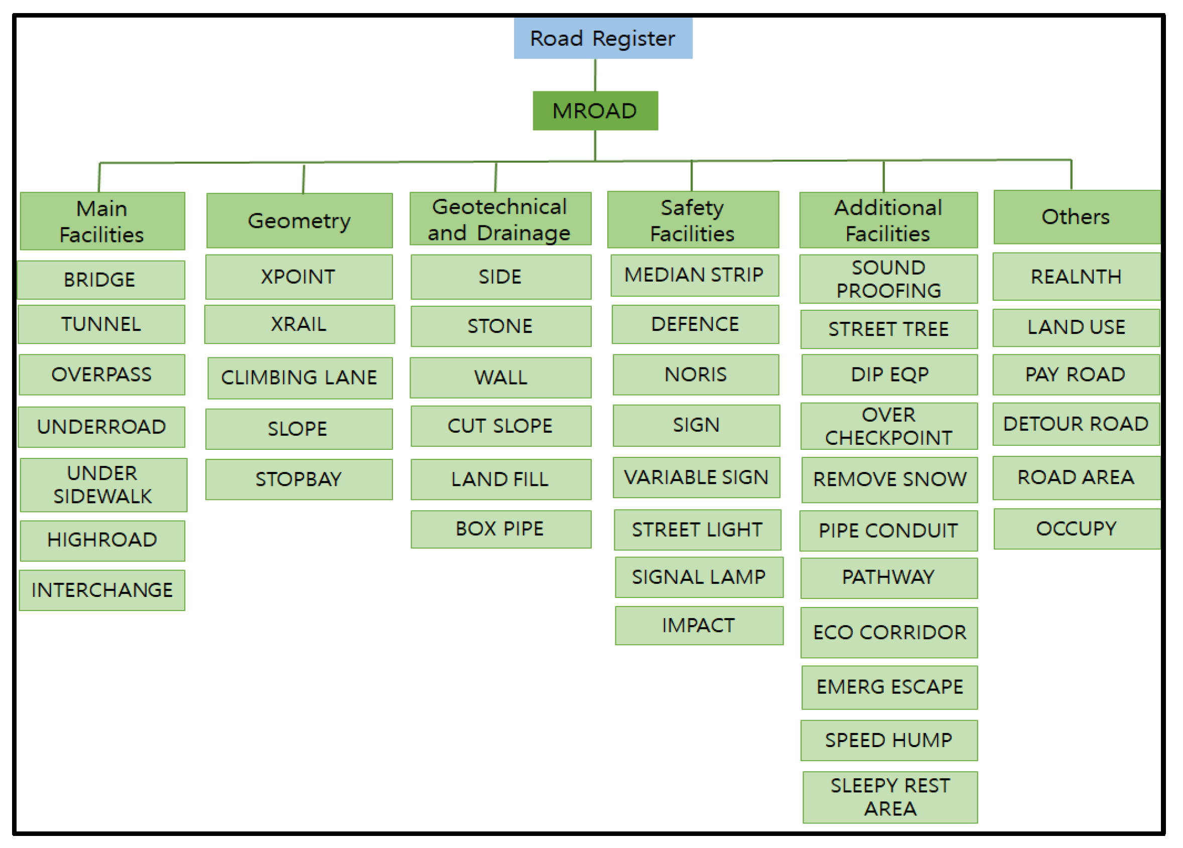
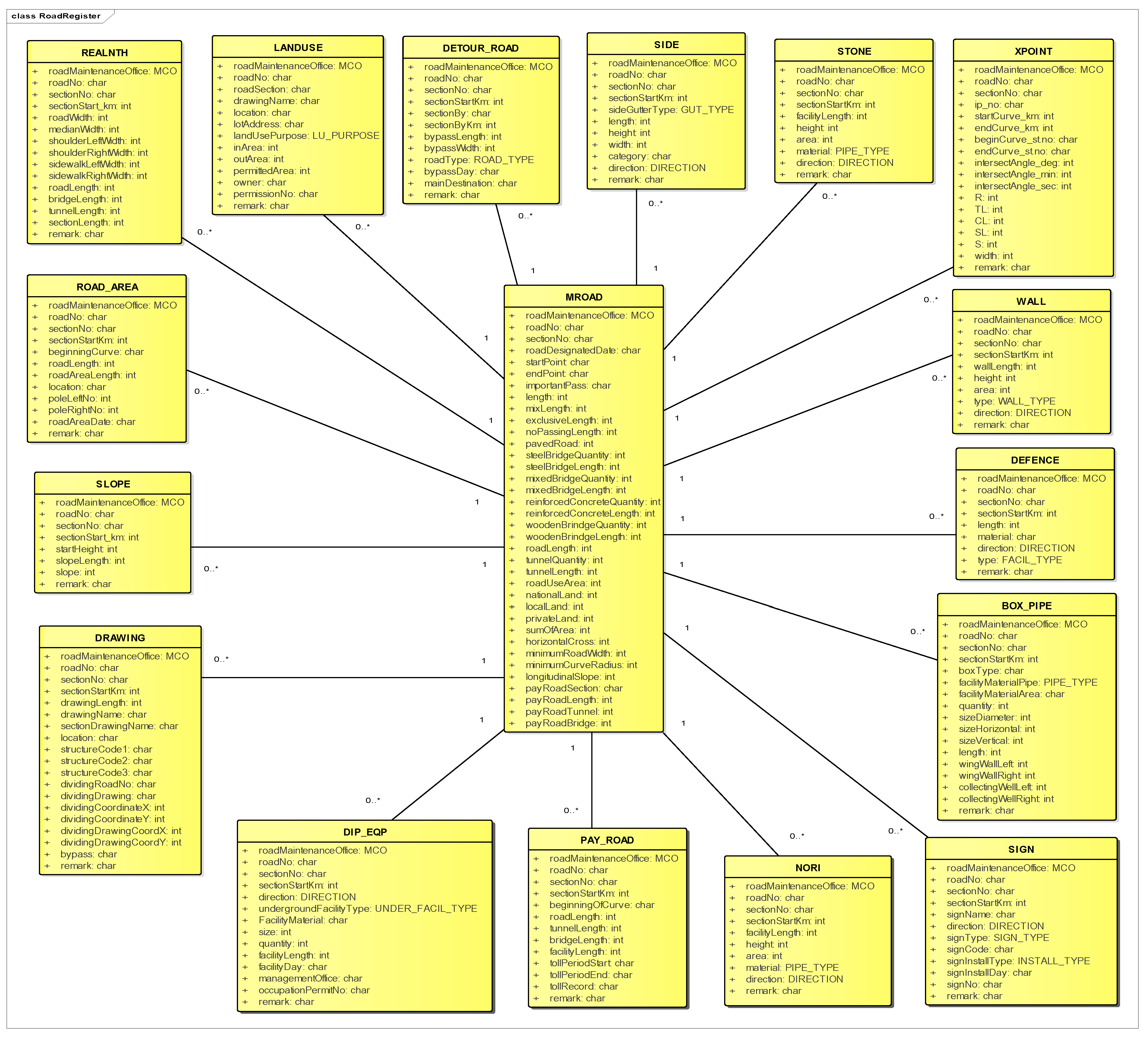
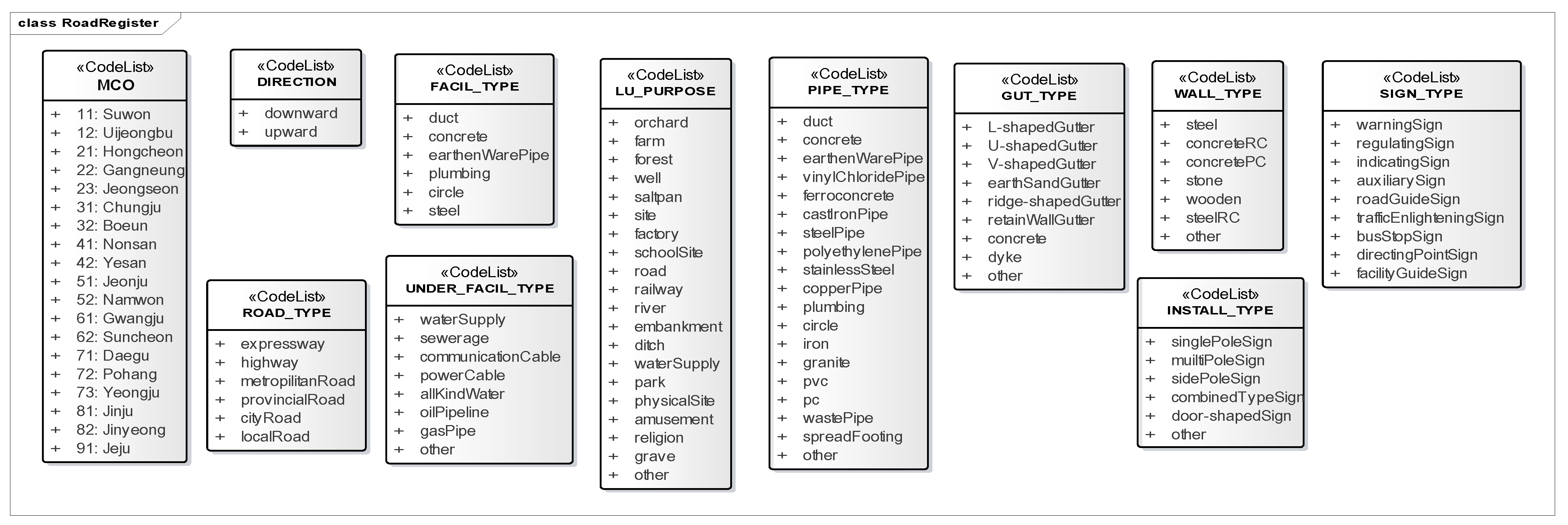
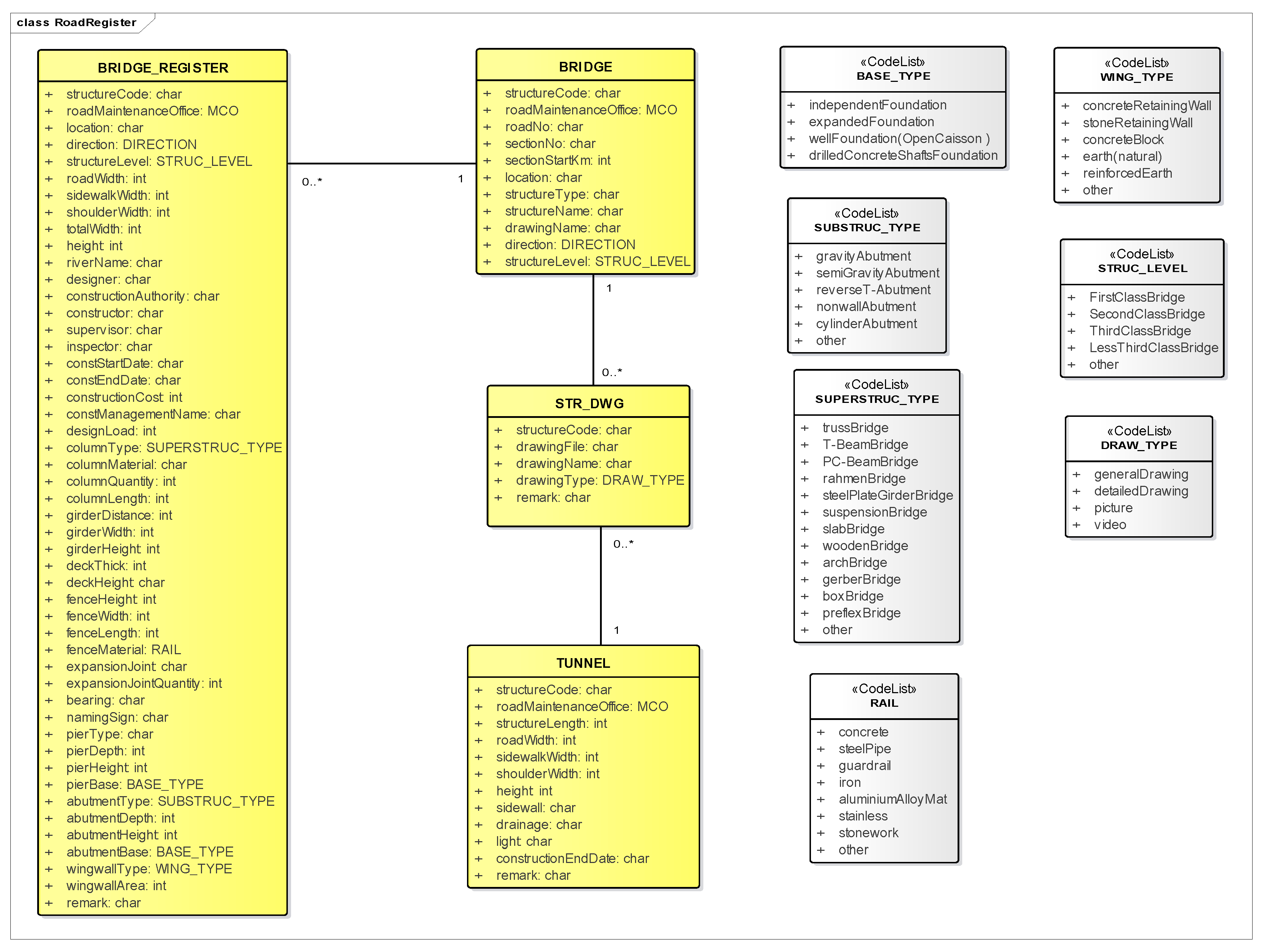
2.1.2. Analysis of Road Register Information System
2.2. Mapping between Classes from the Road Management Model and LandInfra
3. Results
3.1. Proposed Data Model Based on LandInfra Corresponding Parts
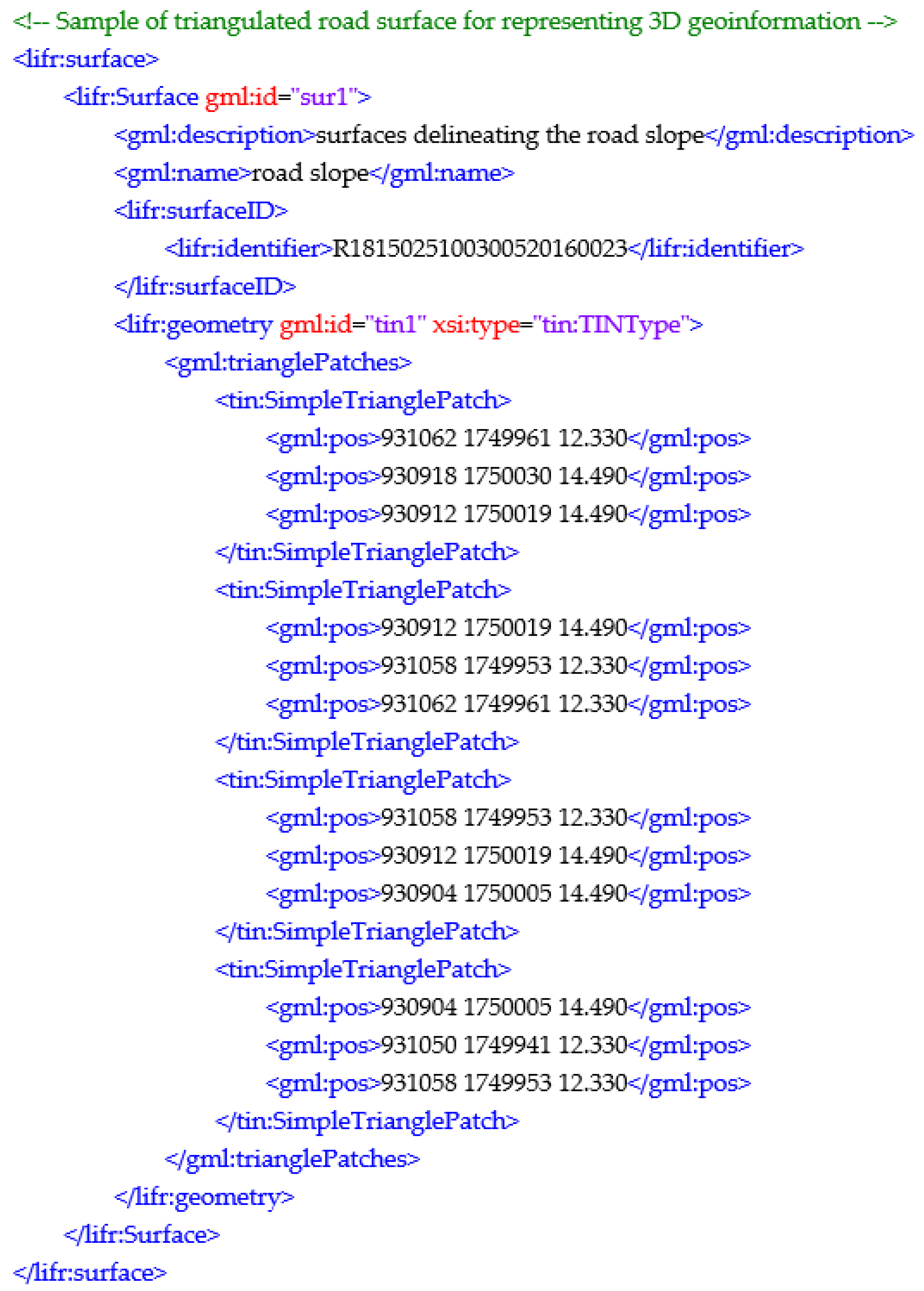
3.2. InfraGML Encoding of the Proposed Data Model for Road Management
4. Discussion
5. Conclusions
Author Contributions
Funding
Institutional Review Board Statement
Informed Consent Statement
Data Availability Statement
Conflicts of Interest
References
- Cafiso, S.; Graziano, A.D.; D’Agostino, C.; Pappalardo, G.; Capace, B. Road Asset Management for Sustainable Development, Environmental Science and Sustainable Development: International Conference on Environmental Science and Sustainable Development (ICESSD 2015); World Scientific: Singapore, 2016; pp. 337–342. [Google Scholar]
- European Union Road Federation. ERF Road Asset Management–An ERF Position Paper for Maintaining and Improving a Sustainable and Efficient Road Network; European Union Road Federation (ERF): Brussels, Belgium, 2014. [Google Scholar]
- Roberts, J. Road infrastructure management systems (RIMS): The main components. Road Transp. Res. 2004, 13, 94. [Google Scholar]
- Labetski, A.; van Gerwen, S.; Tamminga, G.; Ledoux, H.; Stoter, J. A proposal for an improved transportation model in CityGML. Int. Arch. Photogramm. Remote Sens. Spat. Inf. Sci. 2018, XLII-4, 89–96. [Google Scholar] [CrossRef] [Green Version]
- Kiema, J.; Mwangi, J.M. A prototype GIS-based road pavement information and management system. J. Civ. Eng. Res. 2009, 6. [Google Scholar] [CrossRef]
- Morova, N.; Terzi, S.; Gökova, S.; Karaşahin, M. Pavement management systems application with geographic information system method. J. Nat. Appl. Sci. 2016, 20, 103–110. [Google Scholar] [CrossRef]
- Acquah, P.C.; Fosu, C. Implementation of geographic information system application in the maintenance management of roads in Ghana: A case study of roads in Kumasi Metropolis. Am. J. Geogr. Inf. Syst. 2017, 6, 90–102. [Google Scholar]
- Musa, I.J.; Richard, T.S.; Iguisi, E.O. GIS-based road transport infrastructure management system for Adamawa Central, Adamawa State, Nigeria. J. Environ. Earth Sci. 2015, 5, 1–16. [Google Scholar]
- Ministry of Land, Infrastructure and Transport. Study on the Improvement of Road Register Computerization. 2015. Available online: https://www.codil.or.kr/filebank/original/RK/OTKCRK160181/OTKCRK160181.pdf?stream=T (accessed on 1 February 2022).
- Buuveibaatar, M.; Kim, M.G.; Shin, S.P. Towards application of LandInfra standard for highway management in Korea. Int. Arch. Photogramm. Remote Sens. Spat. Inf. Sci.-ISPRS Arch. 2020, 43, 435–439. [Google Scholar] [CrossRef]
- Richard, T.S.; Musa, I.J.; Iguisi, E.O. Development of GIS-based road transport information management system for Adamawa Central, Adamawa State, Nigeria. J. Inf. Sci. Eng. 2015, 5, 56–73. [Google Scholar]
- Korea Institute of Civil Engineering and Building Technology. Development of Highway Management System: 5th Stage. 2003. Available online: https://www.codil.or.kr/filebank/original/RK/OTMCRK040495/OTMCRK040495.pdf?stream=T (accessed on 28 January 2022).
- Buuveibaatar, M.; Shin, S. Design of data model for 3D geospatial information-based highway management using LandInfra standard. Int. J. Highw. Eng. 2021, 23, 87–94. [Google Scholar] [CrossRef]
- Moon, H.; Choi, W.; Kang, L.; Nah, H. Extraction of road structure elements for developing IFC (Industry Foundation Classes) model for road. J. Korea Acad.-Ind. Coop. Soc. 2014, 15, 1195–1203. [Google Scholar]
- Gristina, S.; Ellul, C.; Scianna, A. Developing a 3d road cadastral system: Comparing legal requirements and user needs. Int. Arch. Photogramm. Remote Sens. Spat. Inf. Sci.-ISPRS Arch. 2016, 4, 223–231. [Google Scholar] [CrossRef] [Green Version]
- Hatger, C.; Brenner, C. Extraction of road geometry parameters from laser scanning and existing databases. Int. Arch. Photogramm. Remote Sens. Spat. Inf. Sci.-ISPRS Arch. 2003, 34, 225–230. [Google Scholar]
- Sun, M.; Chen, J. Data structure research of 3D city road network. Int. Arch. Photogramm. Remote Sens. Spat. Inf. Sci.-ISPRS Arch. 2000, 33, 1025–1037. [Google Scholar]
- Zhu, Q.; Li, Y. Hierarchical lane-oriented 3D road-network model. Int. J. Geogr. Inf. Sci. 2008, 22, 479–505. [Google Scholar] [CrossRef]
- OGC (Open Geospatial Consortium). City Geography Markup Language (CityGML) Encoding Standard, Version 2.0.0; OGC: Wayland, MA, USA, 2012. [Google Scholar]
- Kim, B.S.; Jeong, D.W.; Oh, S.H.; Ahn, J.W.; Hong, S.K. Design and implementation of data model for detailed 3D road data. J. Korean Soc. Geogr. Inf. Sci. 2019, 27, 13–23. [Google Scholar] [CrossRef]
- Beil, C.; Kolbe, T.H. CityGML and the streets of New York—A proposal for detailed street space modelling. ISPRS Ann. Photogramm. Remote Sens. Spat. Inf. Sci. 2017, 2–9. [Google Scholar] [CrossRef] [Green Version]
- Beil, C.; Ruhdorfer, R.; Coduro, T.; Kolbe, T.H. Detailed streetspace modelling for multiple applications: Discussions on the proposed CityGML 3.0 transportation model. ISPRS Int. J. Geo-Inf. 2020, 9, 603. [Google Scholar] [CrossRef]
- Jang, H.; Kim, H.; Kang, H. Building large-scale CityGML feature for digital 3D infrastructure. J. Korean Soc. Surv. Geod. Photogramm. Cartogr. 2021, 39, 187–201. [Google Scholar]
- Beil, C.; Kolbe, T.H. Combined modelling of multiple transportation infrastructure within 3D city models and its implementation in CityGML 3.0. ISPRS Ann. Photogramm. Remote Sens. Spat. Inf. Sci. 2020, 6, 29–36. [Google Scholar] [CrossRef]
- Niestroj, M.G.; McMeekin, D.A.; Helmholz, P. Overview of Standards towards Road Asset Information Exchange. 2018, pp. 443–450. Available online: https://www.int-arch-photogramm-remote-sens-spatial-inf-sci.net/XLII-4/443/2018/ (accessed on 19 September 2018).
- Austroads. Data Standard for Road Management and Investment in Australia and New Zealand Version 3.0. No. AP-R597-19; Australia, 2019. Available online: https://austroads.com.au/publications/asset-management/ap-r597-19 (accessed on 30 January 2019).
- Jetlund, K.; Onstein, E.; Huang, L. Information exchange between GIS and geospatial its databases based on a generic model. ISPRS Int. J. Geo-Inf. 2019, 8, 141. [Google Scholar] [CrossRef] [Green Version]
- Kalogianni, E.; Floros, G.S.; Dimopoulou, E.; Skanska, U.K. Investigating transport infrastructure objects within their spatial development lifecycle. ISPRS Ann. Photogramm. Remote Sens. Spat. Inf. Sci. 2021, 8, 129–136. [Google Scholar] [CrossRef]
- Kumar, K.; Labetski, A.; Ohori, K.A.; Ledoux, H.; Stoter, J. Harmonising the OGC standards for the built environment: A CityGML extension for LandInfra. ISPRS Int. J. Geo-Inf. 2019, 8, 246. [Google Scholar] [CrossRef] [Green Version]
- Malmkvist, M.; Axelsson, P.; Wikström, L.; Bergman, O.; Nilsson, A.; Granberg, S.; Jensen, J.; Häggström, E.; Sigfrid, J.; Karlsson, K. Alignment deployment. Implementation report. In Verification IFC Alignment and InfraGML; Technical Report; Nordic Project Team, BuildingSMART: Hertfordshire, UK, 2017. [Google Scholar]
- Kumar, K.; Labetski, A.; Ohori, K.A.; Ledoux, H.; Stoter, J. The LandInfra standard and its role in solving the BIM-GIS quagmire. Open Geospat. Data Softw. Stand. 2019, 4, 1–16. [Google Scholar] [CrossRef] [Green Version]
- Gilbert, T.; Rönsdorf, C.; Plume, J.; Simmons, S.; Nisbet, N.; Gruler, H.; Kolbe, T.H.; van Berlo, L.; Mercer, A. Built Environment Data Standards and Their Integration: An Analysis of IFC, CityGML and LandInfra. Version 1.0, 2 March 2020, OGC Document 19-091r1, bSI TR1012. 2020. Available online: https://portal.ogc.org/files/?artifact_id=92634 (accessed on 4 February 2022).
- Guyo, E.; Hartmann, T.; Ungureanu, L. Interoperability between BIM and GIS through open data standards: An overview of current literature. In Proceedings of the 9th Linked Data in Architecture and Construction Workshop—LDAC2021, Luxembourg, 11–13 October 2021; Volume 3, pp. 5–9. Available online: http://ceur-ws.org/Vol-3081/10paper.pdf (accessed on 14 January 2022).
- Doc. No. 15-111r1; Land and Infrastructure Conceptual Model Standard. OGC: Rockville, MD, USA, 2016.
- LandXML-1.2. Available online: http://landxml.org/About.aspx (accessed on 4 March 2022).
- Document No. 16-104r2; OGC InfraGML 1.0: Part 4–LandInfra Roads-Encoding Standard. OGC: Rockville, MD, USA, 2017.
- Austroads. Guide to Asset Management-Overview Part 1: Introduction; Austroads Ltd.: Sydney, Australia, 2018. [Google Scholar]
- Lei, X.; Wu, P.; Zhu, J.; Wang, J. Ontology-based information integration: A state-of-the-art review in road asset management. Arch. Comput. Methods Eng. 2021, 1–19. [Google Scholar] [CrossRef]
- Road Statistics and Maintenance Information System. Available online: http://www.rsis.kr/statistics_road_national.htm (accessed on 2 February 2022).
- Korea Institute of Civil Engineering and Building Technology. A Planning Study on Smart Road Management Integration System and Elementary Technology. 2018. Available online: https://www.codil.or.kr/filebank/original/RK/OTKCRK190422/OTKCRK190422.pdf?stream=T (accessed on 4 February 2022).
- Ministry of Land Infrastructure and Transport. Road Duty Handbook. 2021. Available online: https://www.codil.or.kr/filebank/original/MA/OTKCMA211234/OTKCMA211234.pdf?stream=T (accessed on 22 March 2022).
- Document No. 16-100r2; OGC InfraGML 1.0: Part 0–LandInfra Core–Encoding Standard. OGC: Rockville, MD, USA, 2017.
- Document No. 16-102r2; OGC InfraGML 1.0: Part 2–LandInfra Facilities and Projects–Encoding Standard. OGC: Rockville, MD, USA, 2017.
- Document No. 16-103r2; OGC InfraGML 1.0: Part 3–LandInfra Alignments–Encoding Standard. OGC: Rockville, MD, USA, 2017.
- Schaller, J.; Gnaedinger, J.; Reith, L.; Freller, S.; Mattos, C. GeoDesign: Concept for Integration of BIM and GIS in Landscape Planning. J. Digit. Landsc. Archit. 2017, 2, 102–112. [Google Scholar]


| No. | Class Name | Description |
|---|---|---|
| 1 | PMS_ROUTE_GENERAL | Route information |
| 2 | PMS_EVENT | Event information |
| 3 | PMS_EVENT_CODE | Event code |
| 4 | PMS_REHAB_CODE | Road maintenance code |
| 5 | PMS_TRF_VOL | Traffic volume |
| 6 | PMS_ROUTE_CODE | Route code |
| 7 | PMS_PR_CODE | Administrative area code |
| 8 | PMS_MCO_CODE | Management office code |
| 9 | PMS_ASP_STRUC | Asphalt structure |
| 10 | PMS_CON_STRUC | Concrete structure |
| 11 | PMS_PAV_SURV | Pavement condition |
| No. | Class Name | Description | Spatial Data Type | Presence of Data |
|---|---|---|---|---|
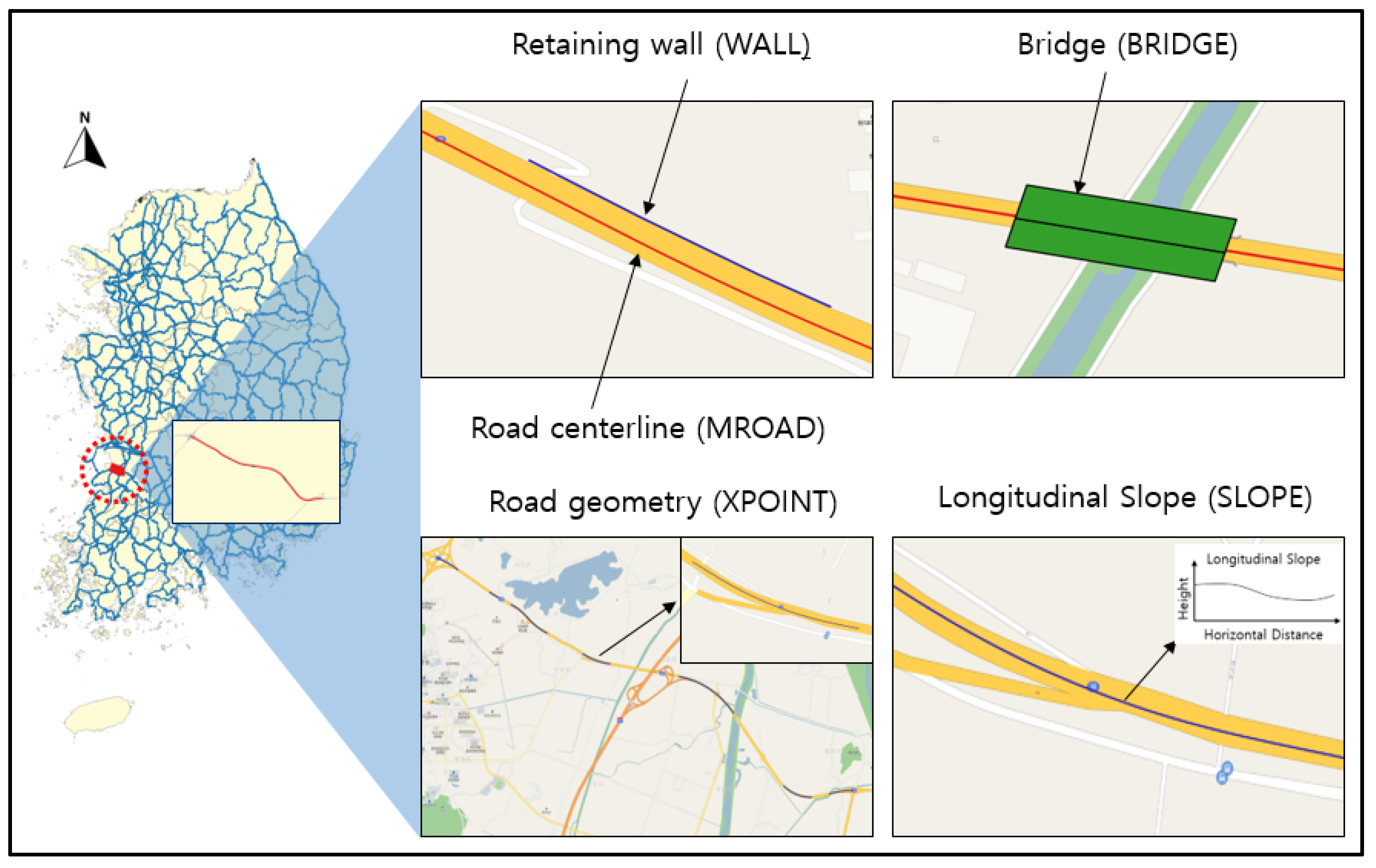
| 1 | MROAD | Road register | Line | Yes |
| 2 | REALNTH | Real length | Line | Yes |
| 3 | LANDUSE | Road space/area | Polygon | No |
| 4 | DETOUR_ROAD | Detour road | Line | No |
| 5 | SIDE | Side gutter | Line | Yes |
| 6 | STONE | Stone embankment | Line | No |
| 7 | XPOINT | Road geometry | Line | Yes |
| 8 | WALL | Retaining wall | Line | Yes |
| 9 | DEFENCE | Guardrail | Line | Yes |
| 10 | BOX_PIPE | Drainage culvert and pipe | Polygon | Yes |
| 11 | SIGN | Road sign | Point | Yes |
| 12 | NORI | Rockslide prevention facility | Line | No |
| 13 | PAY_ROAD | Toll road | Line | No |
| 14 | DIP_EQP | Underground facility | Line | Yes |
| 15 | DRAWING | Drawing | - | No |
| 16 | SLOPE | Longitudinal slope | Line | Yes |
| 17 | ROAD_AREA | Area near road | Polygon | No |
| 18 | BRIDGE_REGISTER | Bridge register | Polygon | No |
| 19 | BRIDGE | Bridge | Polygon | Yes |
| 20 | STR_DWG | Structural drawing | - | No |
| 21 | TUNNEL | Tunnel | Polygon | NA |
| No. | Road Management Class | LandInfra Class | Part |
|---|---|---|---|
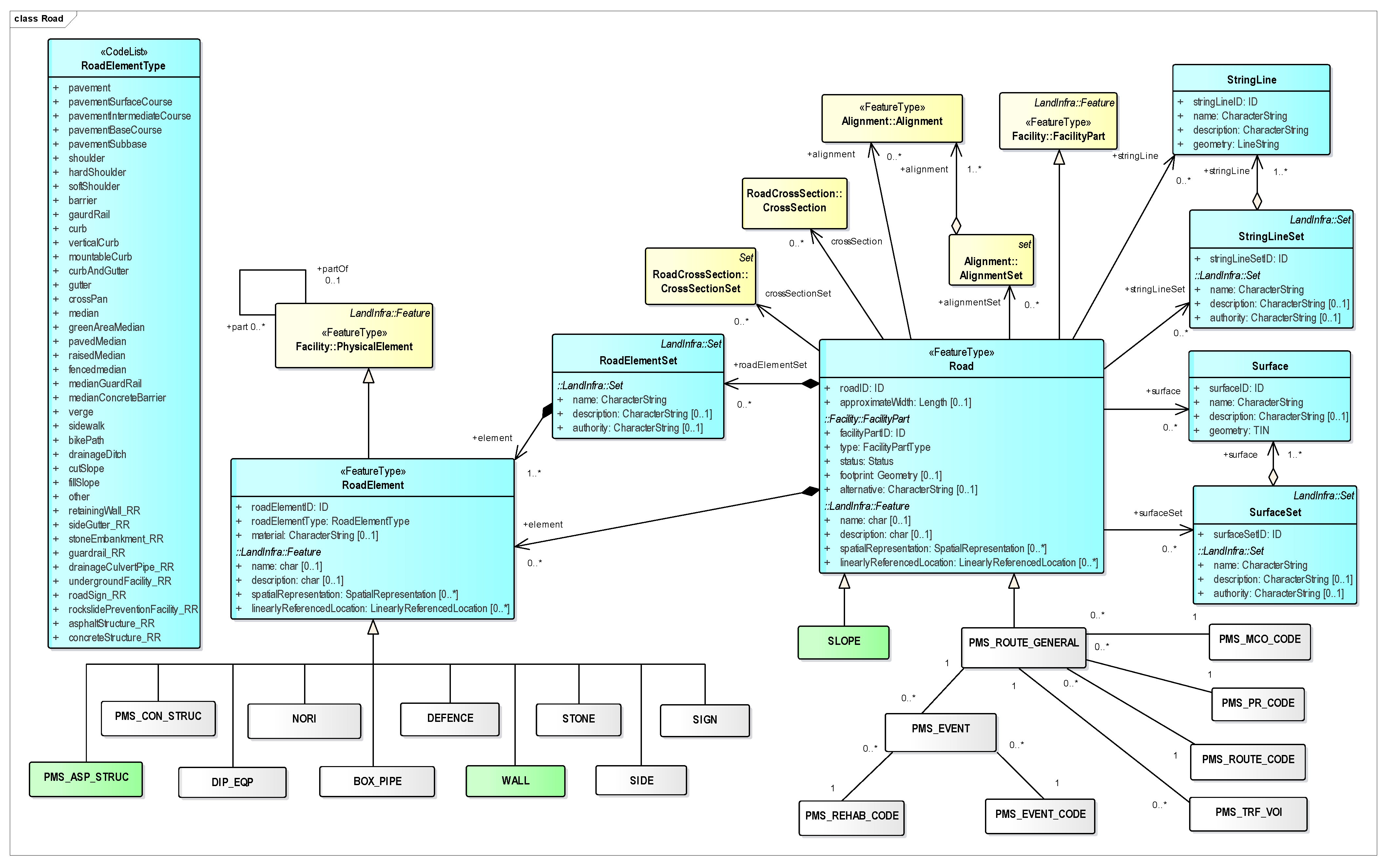
| 1 | PMS_ASP_STRUC | RoadElement | Road |
| 2 | PMS_CON_STRUC | RoadElement | Road |
| 3 | PMS_PAV_SURV | PhysicalElement | Facility |
| 4 | PMS_ROUTE_GENERAL | Road | Road |
| 5 | PMS_TRF_VOL | Road | Road |
| 6 | PMS_ROUTE_CODE | Road | Road |
| 7 | PMS_PR_CODE | Road | Road |
| 8 | PMS_MCO_CODE | Road | Road |
| 9 | PMS_EVENT | Road | Road |
| 10 | PMS_EVENT_CODE | Road | Road |
| 11 | PMS_REHAB_CODE | Road | Road |
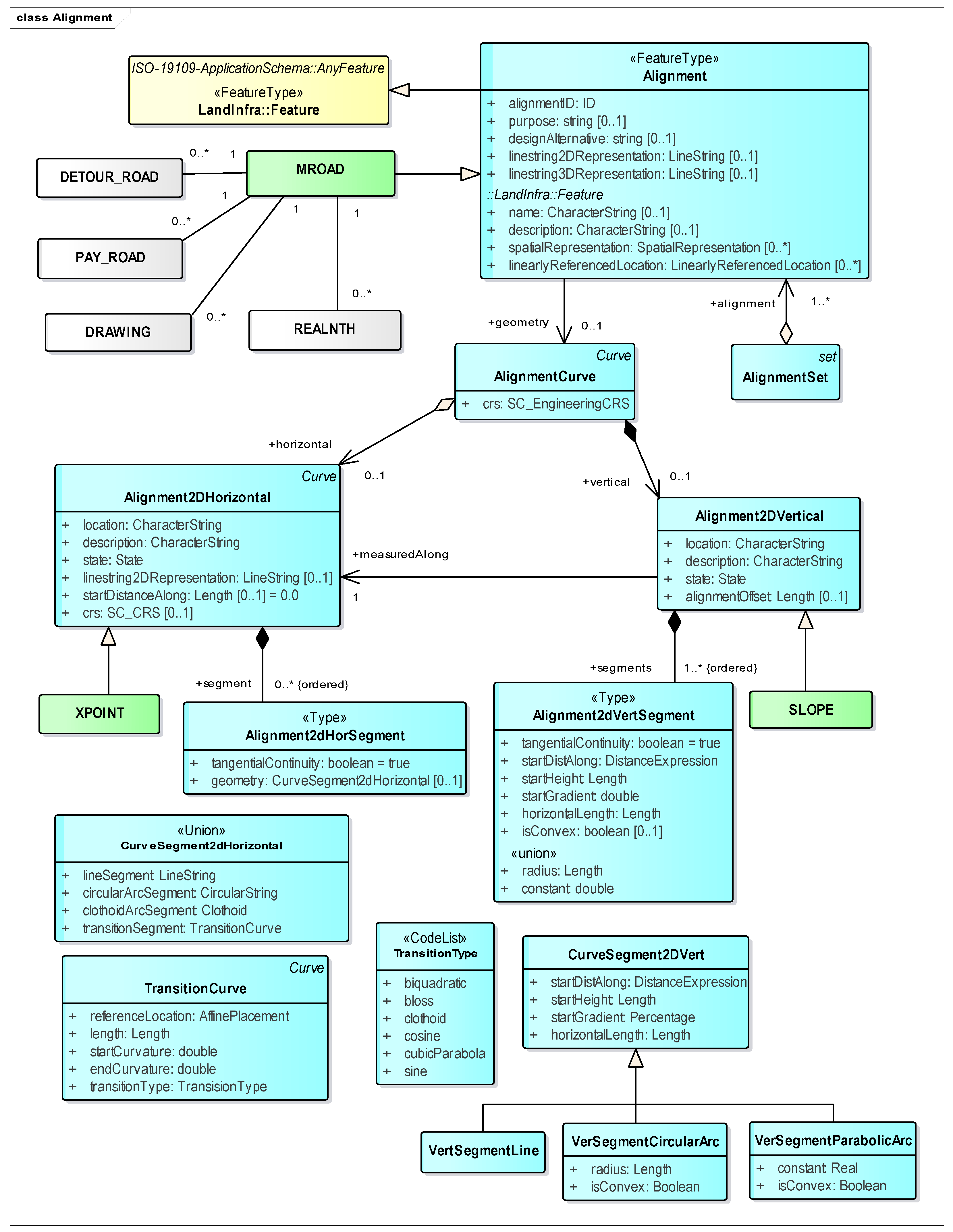
| 12 | MROAD | Alignment | Alignment |
| 13 | REALNTH | Alignment | Alignment |
| 14 | LANDUSE | PhysicalElement | Facility |
| 15 | DETOUR_ROAD | Alignment | Alignment |
| 16 | SIDE | RoadElement | Road |
| 17 | STONE | RoadElement | Road |
| 18 | XPOINT | Alignment2DHorizontal | Alignment |
| 19 | WALL | RoadElement | Road |
| 20 | DEFENCE | RoadElement | Road |
| 21 | BOX_PIPE | RoadElement | Road |
| 22 | SIGN | RoadElement | Road |
| 23 | NORI | RoadElement | Road |
| 24 | PAY_ROAD | Alignment | Alignment |
| 25 | DIP_EQP | RoadElement | Road |
| 26 | DRAWING | Alignment | Alignment |
| 27 | SLOPE | Road | Road |
| Alignment2DVertrical | Alignment | ||
| 28 | ROAD_AREA | PhysicalElement | Facility |
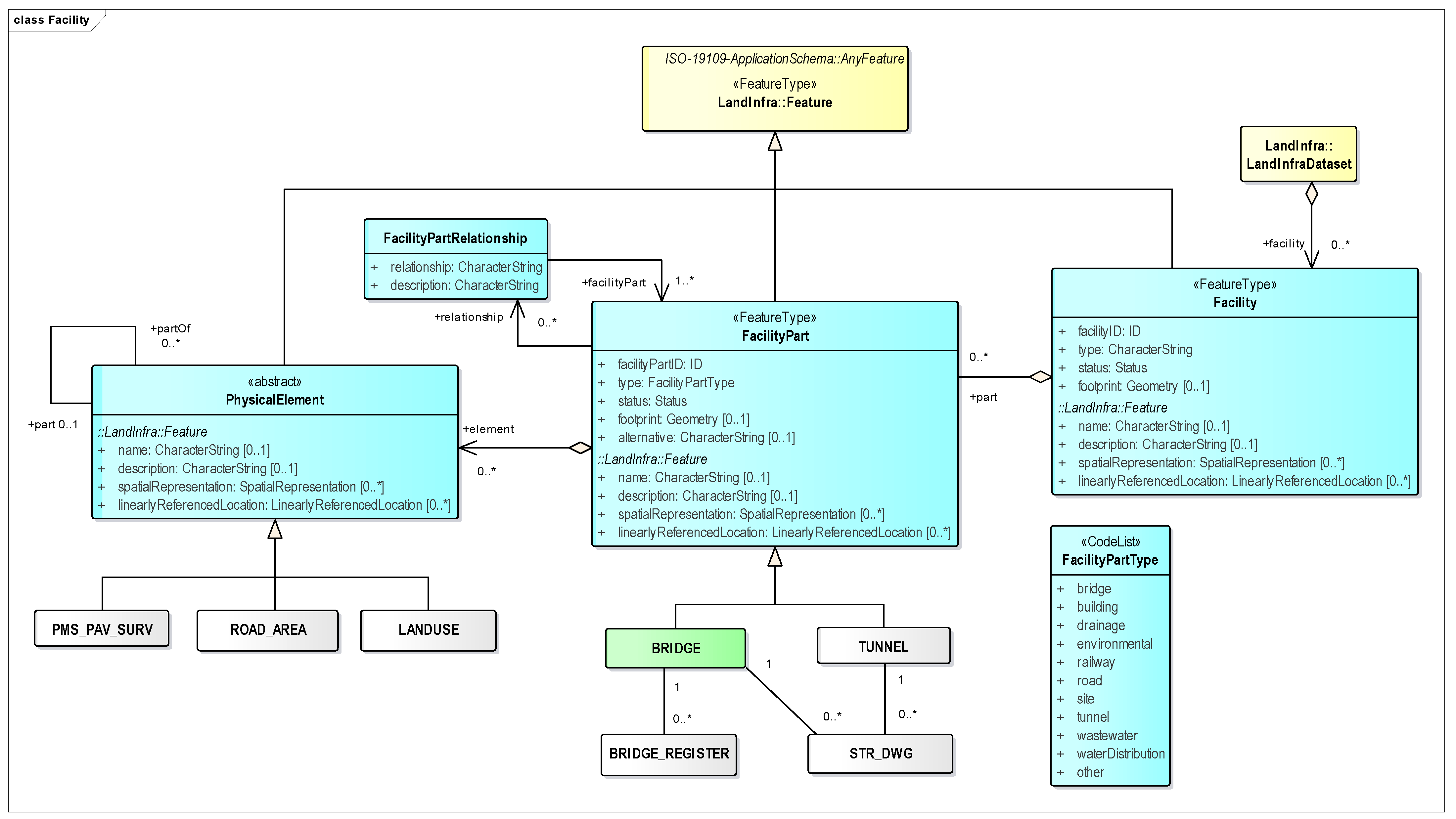
| 29 | BRIDGE_REGISTER | FacilityPart | Facility |
| 30 | BRIDGE | FacilityPart | Facility |
| 31 | STR_DWG | FacilityPart | Facility |
| 32 | TUNNEL | FacilityPart | Facility |
Publisher’s Note: MDPI stays neutral with regard to jurisdictional claims in published maps and institutional affiliations. |
© 2022 by the authors. Licensee MDPI, Basel, Switzerland. This article is an open access article distributed under the terms and conditions of the Creative Commons Attribution (CC BY) license (https://creativecommons.org/licenses/by/4.0/).
Share and Cite
Buuveibaatar, M.; Lee, K.; Lee, W. Development of a Conceptual Data Model for 3D Geospatial Road Management Based on LandInfra Standard: A Case Study of Korea. ISPRS Int. J. Geo-Inf. 2022, 11, 316. https://0-doi-org.brum.beds.ac.uk/10.3390/ijgi11050316
Buuveibaatar M, Lee K, Lee W. Development of a Conceptual Data Model for 3D Geospatial Road Management Based on LandInfra Standard: A Case Study of Korea. ISPRS International Journal of Geo-Information. 2022; 11(5):316. https://0-doi-org.brum.beds.ac.uk/10.3390/ijgi11050316
Chicago/Turabian StyleBuuveibaatar, Munkhbaatar, Kangjae Lee, and Wonhee Lee. 2022. "Development of a Conceptual Data Model for 3D Geospatial Road Management Based on LandInfra Standard: A Case Study of Korea" ISPRS International Journal of Geo-Information 11, no. 5: 316. https://0-doi-org.brum.beds.ac.uk/10.3390/ijgi11050316