Article

Remote Sensing and GIS Applied to the Landscape for the Environmental Restoration of Urbanizations by Means of 3D Virtual Reconstruction and Visualization (Salamanca, Spain)

by
Antonio Miguel Martínez-Graña
* and
Virginia Valdés Rodríguez
Geology Department, External Geodynamics Area, Faculty of Sciences, University of Salamanca, Plaza Merced s/n, 37008 Salamanca, Spain
*
Author to whom correspondence should be addressed.
ISPRS Int. J. Geo-Inf. 2016, 5(1), 2; https://0-doi-org.brum.beds.ac.uk/10.3390/ijgi5010002
Submission received: 1 July 2015 / Revised: 15 November 2015 / Accepted: 30 November 2015 / Published: 6 January 2016

Abstract

:
The key focus of this paper is to establish a procedure that combines the use of Geographical Information Systems (GIS) and remote sensing in order to achieve simulation and modeling of the landscape impact caused by construction. The procedure should be easily and inexpensively developed. With the aid of 3D virtual reconstruction and visualization, this paper proposes that the technologies of remote sensing and GIS can be applied to the landscape for post-urbanization environmental restoration. The goal is to create a rural zone in an urban development sector that integrates the residential areas and local infrastructure into the surrounding natural environment in order to measure the changes to the preliminary urban design. The units of the landscape are determined by means of two cartographic methods: (1) indirect, using the components of the landscape; and (2) direct methods, using the landscape’s elements. The visual basins are calculated for the most transited by the population points, while establishing the zones that present major impacts for the urbanization of their landscape. Based on this, the different construction types are distributed (one-family houses, blocks of houses, etc.), selecting the types of plant masses either with ornamentals or integration depending on the zone; integrating water channels, creating a water channel in recirculation and green spaces and leisure time facilities. The techniques of remote sensing and GIS allow for the visualization and modeling of the urbanization in 3D, simulating the virtual reality of the infrastructure as well as the actions that need to be taken for restoration, thereby providing at a low cost an understanding of landscape integration before it takes place.

1. Introduction

The term “landscape” integrates a set of natural and human elements that interact within a territory [1,2,3]. The landscape constitutes a valuable resource and its aesthetics are a result of the interaction between geology, geomorphology, climate, soils, vegetation, hydrology and human activities [4,5,6,7,8].
The integration of human activities or buildings can provoke or bring about a negative impact on the components of the natural environment; therefore, it is necessary to protect it by developing specific regulations. The regulation of these impacts falls under the “European Agreement of the Landscape” [9]. Because the agreement defines landscape as any part of the territory perceived to have been influenced by the population, as a result of the action and interaction between the natural and human factors, the establishment of measures for its protection, management and arrangement in accordance with the European standards was deemed necessary [10,11,12,13].
In Spain, the laws of soil, urbanism and environmental evaluation state that all constructions and buildings must adapt to the environment, taking the necessary measures to harmonize with the landscape and not distort it [14,15,16,17,18,19]. These parameters therefore require the establishment and cataloging of the units of the landscape at a regional level, in order to establish the directives of arrangement. For instance, any action that would affect soil in terms of its distribution, use, height, volume, color, composition, and materials must adapt to the surrounding landscape and preserve the vegetation as well as the natural slopes of the area.
Through 3D visualization and an analysis of spatial distribution, remote sensing and Geographical Information Systems (GIS) are helpful tools used in the design of urban areas [20,21,22,23]. They promote the evaluation and decision-making processes in the territorial planning of the project with the assistance of the inexpensive and easy-to-use process of Building Information Modeling (BIM), in addition to augmented reality tools found on the Google Earth free platform.
In this paper, we discuss the BIM applied to the municipality of Zarapicos, north of the outskirts of the city of Salamanca. This region is of interest because it is undergoing construction of an urbanized settlement (hereafter Z5) and because there is already a great deal of construction, at varying degrees of completion, at a nearby golf course that shares infrastructure with Z5 (Figure 1). The land area for the project Z5 is 57 ha and is surrounded by “solar fields” of photovoltaic plates to the north, east and west. The density of housing is 20 houses/ha, with 0.35 m2/m2 as the coefficient of edificability. The general arrangement of the sector is as follows: (1) predominant use: residential one-family houses, hotels and community services; (2) compatible uses: collective housing and community services, gas stations, offices and solar power plants; and (3) prohibited uses: industrial and agricultural livestock. Thus, the primary planned usage is residential. The residential soil zones are divided into three types of housing: one-family row houses, one-family detached houses, and houses on open blocks (Figure 1). The use of urban furnishing is subdivided into different zones: community services and private use; sports facilities; and free public and road spaces. The zone allocated for industrial use will include a solar park. The areas dedicated to the community’s private and public services will have swimming pools and other sports facilities.
Figure 1. Study area (left) and distribution of the community services and residential uses (right).
Ijgi 05 00002 g001
The aim of this research was to establish a BIM for a 3D virtual reconstruction of the completed subdivision, in order to map out the geomorphological integration of Z5 into the environment and to plan for green spaces and gardens to make the interior of the urbanized subdivision seem more natural. These environmental improvements can be manifested in one of three ways. The first is to regenerate the green spaces that were damaged or altered (e.g., tree removal, machinery traffic, etc.) during construction and modifying the morphology of the area accordingly.
The second is to integrate the main water channels and the channel that transverses the watercourse, which crosses the sector in a South−North (N-S) direction, so that a more natural state—one that is in line with the current ecosystem—is achieved. The third is by analyzing the visual basin of the different sectors together with the synergies and its effects to calculate the landscape impact of the Z5 project on the different soil uses. Subsequently, preventative and corrective techniques based on virtual efficiency, such as the efficiency of the vegetal visual barriers or the creation of leisure areas, can be established.
The main contribution of this paper is the utilization of remote sensing and GIS to simulate the Urban Furnishing in 3D in order to anticipate the landscape impact prior to the construction of the technical project. The innovation is such that the indicated procedure is analyzed from the digital models LiDAR (Light Detection and Ranging) sensor with a pixel of 5 m. An overlap of the aerial photographs establishes the visual basins of the residential areas and equipment zones, thereby integrating and minimizing the impact on the landscape.

Characteristics of the Study Area

From a climatic point of view, the Z5 project is located in the climate of the Mediterranean region, of the bioclimatic meso-Mediterranean stage. The climatic condition of the zone is characterized by cold winters and warm summers, presenting a minimal average temperature of 21 °C in January and a maximum temperature of 39 °C in July. There are icings in January, with a minor probability of icings occurring in the months of November and April. In terms of precipitation, the project area is characterized by the presence of a dry period with precipitation of 30 mm/month during the summer period, and a period of major precipitation between 30 mm and 60 mm/month during the winter.
Geologically, the context of the project is the Duero basin, which is a depression in the terrain, according to a few morphotectonic guidelines. It was refilled during the Cenozoic era with sandy deposits formed by an overlapping of the alluvial fans, resulting from the erosion of the mountainous surrounding areas. Consequently, the lithology is constituted of more or less sandy deposits (from the granitic reliefs of the adjacent saws), or sandy-clayey (arising from metasediments from schist and gray wackes). During the Quaternary, the erosion of these geological materials by the fluvial fitted processes of the Tormes River and its tributaries resulted in the formation of fluvial terraces and erosion surfaces, constituting singing sands, gravels, sands, slimes and clays, inherited from the arkosic materials. Z5 is built upon sandstones from the Paleogene and Neogene ages, and the gravels, sands and clays are alluvial funds of the Quaternary age (Figure 2).
The geomorphological analysis shows that project Z5 is located in the peneplain of Salamanca with a difference in relief formed from tectonic readjustment movements that unbalance the Paleozoic blocks and the overlying sediments. The fluvial network generates wavinesses in the area, caused by erosion and subsequently developing into a series of hills and bedrock forms directly related to the lithological hardness due to the appearance of cemented sandstones. The waviness of the area concentrates the runoff in the depressed zones. In the hills or polygenic surfaces, the waviness of the area predominates over the erosion processes, resulting in the loss of the pedological cover and the substratum outcrop. These intensive erosive processes are shown by the formation of gulleys and rills. Therefore, polygenic surfaces appear with hillsides in the high zones of the hills, where the gulley’s water laminates and concenters in the creeks and riverbeds of a major entity, presenting a major generating deposit of terraces and creating the bottom of the valley (Figure 3).
The soils are leptosol and cambisol sands, with a marked anthropogenic character due to the agricultural and ranching activities that are carried out on them. It is a question of soils with little depth and high instability, due to the effect of the successive droughts and rains in the highest zones of the area; the materials that are lost are accumulated in the zones of the watercourse or the valley. The thickness of the soil varies in the different zones of the sector, being practically non-existent in those zones of the mother rock (in polygenic summits and high hillside), and at its maximum thickness in the zones of watercourse. Generally, it is arranged in three horizons: (1) a superficial horizon “Ap,” with a yellowish color, a free or clotted structure, and a low content in organic matter and singings of quartzite of diverse sizes, both appearing on the surface and in the mass of the soil; (2) a low horizon “C” type placed between the rock mother and the superficial horizon, up to a maximum depth of 80 cm, containing a high mineralogical content, a compact structure and a clear color; and (3) the horizon “R,” corresponding to the unaltered mother rock.
Figure 2. Lithological distribution in the study area and relief in Google Earth.
Ijgi 05 00002 g002
From the point of view of the vegetation, we are inside the Supramesomediterranean Salmantina, Lusitano-Duriense and Orensano-Sanabrense climate series of the oak (Genistrohystricis-Querceto rotundifoliae sigmetum). The associated Genisto hystricis-Quercetum rotundifoliae constitutes the climax stage, but as a very anthropized area, elements of this climax vegetation are rarely found. The zone thus presents diverse vegetable communities. Nitrophilous pastures are developed in those zones with high anthropogenic influence, such as boundaries and limits of infrastructures. In the most developed zone, the watercourse comprises arranged meadows, naturalized by annual and vivacious species, as well as by rocky species. The opened zones of the sector rely on a vegetable coverage of scanty density, composed of different species of bushes and herbaceous plants; almost all of them are vivacious and derived from the undergrowth of a grove of evergreen oaks present in the zone long ago. Only five specimens or form of holm oaks distributed and isolated by the whole sector remain. Apart from these, a forest of pine grove of the productive character in the left margin of the principal watercourse is in a bad vegetative state due to the lack of forestry maintenance and increase in exploitation.
In general, it is a question of species lacking interest in its conservation, neither they nor the ecosystem on which they develop possess any kind of environmental protection because they present a low level of biodiversity and a high degree of degradation. The fauna present in the zone of study is constituted by communities of vertebrates and invertebrates. The fauna has a small influence on the landscape because of its negligible parameter.
Figure 3. Distribution of geomorphological units in the study area.
Ijgi 05 00002 g003
The socioeconomic context of the municipality on which one agrees with the constructive project, presents agriculture as the principal economic activity, as well as the big estates of pastures of holm oak for cattle usage. Low demography, which is in a state of regression, was caused by the emigration of the inhabitants of the cities since 1950. Almost 50% of the surface of the municipality is devoted to agriculture, and 40% is devoted to rearing bovine and sheep livestock. The urbanization will lead to an increase in both direct and indirect employment. During the construction phase, temporary jobs are generated through the tasks of earthmoving, in addition to transporting material. Once construction is complete, direct jobs consisting of the maintenance of the sector and additional indirect activities will be created.
Finally, the space-time historical analysis was carried out from aerial photographs sequenced for the years 1956, 1997, 2002, and 2011, by observing the evolutionary changes of the relief in the zone of study and its natural conditions. Focusing first on the curvature of the channel that crosses the project over time, a stable tracing was observed. In the year 1956, this channel presented a curvature that was less sinuous in later years, presenting in the year 2011 a curvature with the most sinuosity. With regards to the vegetation, it does not undergo much transformation; nevertheless, the arboreal freightage that was found in the southern zone diminished slightly in the year 1997 compared to the year 1956, and it was more or less constant in subsequent years. The appearance of a pine forest repopulation from the year 1997 must be noted. The most notable changes in the landscape appeared with the introduction of a golf course in the southern zone, such that it became visible for the first time in photography in the year 1997, and the installation of solar parks in the photography of the year 2011. In regards to the network of roads, they did not present a great variation in the installation of the solar parks, due to the lack of network access road until the year 2011.

2. Experimental Section

To establish a series of actions ensuring integration of the subdivision with the environment, we analyzed the constituent units of the landscape. We then conducted an analysis of the impacts that might occur on the landscape due to urban development by studying the visual basins from different points of observation. This helped us to determine the zones of major visual fragility in which restoration efforts would consequently have to be focused on [24,25,26]. Indirect and direct methods were used and are described below.

2.1. Indirect Methods

The indirect methods consisted of the identification of the distinct units that made up the current landscape of the zone. The landscape units corresponded to the portions of the territory where the landscape possessed a certain degree of homogeneity in its perceptual characteristics, as well as a certain degree of visual autonomy [27,28,29]. Identification was done using lithological, geomorphologic and vegetation mapping, specified to the area of study. As the existing maps of these variables did not contain a sufficient level of detail, they were developed purposely for the area of study.
The lithological map developed for the sector as shown in Figure 2 presented a slightly varied lithology. The yellow sandstones belonging to the formation of “Cabrerizos” constituted the dominant formation, spreading over the whole sector except for the zone of the watercourse that crossed the sector in the S−N direction, consisting of rock, gravel, sand and silt of sedimentary fluvial origin. The sandstones appeared in the highest zones of the hillsides and in the summits, due to erosion by the runoff of the surface alteration layer [30].
The geomorphological map was developed from a Triangular Irregular Network (TIN) obtained from the digital terrain model, the slope map and the topographic map. We differentiated three geomorphological units in this sector, one of which was the bottom of the valley or watercourse that crossed the sector in the S−N direction (as well as smaller ones in this range) and which will henceforth be referred to in this study as the principal watercourse or “channel.” When designing the urban development, it was taken into account that, during the rainy season, the watercourses collect the runoff from the sector. The dominant forms were the hillsides, and their slopes varied depending on the point at which they were located. Thus, according to the slope map, the slopes on the southern side of the principal watercourse presented an inclination of around 60°, while in the zones nearer to the outer roads, the slope was very low. The steepest slopes were ruts, caused by erosion due to runoff. The hills or the polygenic surfaces constituted the highest zones of the sector, and were therefore the most visible zones. In the latter, the bedrock emerged at the surface due to erosion and runoff.
The mapping of slopes in the area of study showed very high slopes in the hillside of the principal riverbed. The lower slopes were delimited by topographically higher zones, whereas the intermediate slopes were delimited by the hillsides of the interfluvial zones. The altitudinal striping was estimated using the TIN model.
The mapping of the vegetation was developed from the digitalization of the Aerial Orthography National Plan ortophotos of maximum resolution, differentiating between three types of vegetation: pasture vegetation, bush vegetation, and trees, such as pine and oak. Combining these three maps (lithology, geomorphology and vegetation) using GIS resulted in the landscape map consisting of nine different units.
In studying the map, it appears that the hills are located on the sandstones. The major portion of the map is dedicated to pasture vegetation, since the bedrock shows on the surface and lacks a layer of superficial alteration capable of supporting greater vegetation. The hillsides also rest on the sandstones; the vegetation they support varies depending on the area, with pasture and bushes being predominant. As mentioned earlier, the hillsides with more pronounced slopes that lack vegetation are ruts which are caused by erosion, due to runoff. As for the valley bottoms, the principal watercourse is seated on an alluvial material such as rock, gravel, sand, silt and clay, and its vegetation consists of trees such as oak. The other watercourses are located in sandstone, and areas dedicated to pasture. Vegetation made up of oak trees can be found to the north of the zone and to the west of the principal watercourse. The actions to be taken on the watercourse are included in the “Partial Plan” and will, therefore, not be taken into account with regard to the effects of the restoration. Turning now to the vegetation, we noticed the presence of a productive pine forest in the left range of the principal watercourse that is in a degraded state due to neglect. Although not included within the units, the zone situated farther north of the sector, included in the zoning of the Partial Plan as an industrial area—and which is an installation of photovoltaic panels—severely disrupts the naturalness of the landscape (Figure 4).

2.2. Direct Methods: Visual Basins and Landscape Impacts

The zone of study presents a seminatural landscape, such that the biotic elements are combined with man-made elements. Generally speaking, the landscape can be defined by its visual components. Thus, in terms of its form, it is a surface that tends to be regular, with lower inclines near the surface and steeper inclines on the slopes of the valleys or valley bottoms. The promontories of the outcrops of the rocky substratum in the highest zones are contrasted with the nearby valley bottoms. As for the color, there is a chromatic variety of light yellow and ochre colors in its lithology standing out against the range of greens of the vegetation, that consist mainly of planted pasture and meadows of oak. The texture is a result of the size of the medium-coarse grain—a sparse density dispersing at certain points, but becoming thicker at other points—presenting a regularity regarding the arrangement of the different landscape units, and a good internal contrast. As for the scale, the size occupied by the sector is relatively small in relation to the zone of the integrated one. Finally, it is possible to define this as a landscape that is open and continuous with the environment; in addition, it is integrated with the panorama since, from the highest observation zones, the horizontal aspects dominate with amplitude and grandeur.
The man-made elements disrupting the naturalness of the area include the solar park, installations of photovoltaic solar power arranged around the edges of Z5, a golf course located in the south, and a network of unpaved roads and electrical lines.
The special importance that the principal watercourse or channel has relating to the landscape is taken into consideration as it is an area, in terms of the landscape of the territory, in which the visual units are perfectly defined and differentiated. It appears as a visual corridor that crosses the territory, thus generating a certain contrast of color, line and texture with the environment. In addition, given that it is an area linked to a fluvial riverbed, it presents a seasonal dynamism caused by the variation of its two components, vegetation and water, which cause very striking changes in its visual basic elements across the various seasons.
The direct methods used in this research include an analysis of: the visual basin; the recipient of the landscape alteration caused by the urban development; and of every type of element (housing, facilities, etc.) with its own characteristics (height, topographic position, etc.). Through the likelihood that they will be visible from specific points of observation, we were thus able to decide which zones were the most susceptible to visual fragility. The result of this analysis was kept in mind when the actions needed to reduce the impact of the urban sector on the environment were subsequently considered. This analysis was undertaken from both intrinsic and extrinsic perspectives, and made use of ArcGIS v.10.2 automatic processing techniques (Figure 5).
Figure 4. Determination of the landscape units by indirect methods and extrusion 3D with solar parks.
Ijgi 05 00002 g004
Figure 5. Visibility analysis by indirect methods: visual basins of (A) the nearest villages; (B) visual basins of roads; visual basins of (C) the principal watercourse; and direct methods: visual basins of (D) points of observation. Down: extrusion (left) and anaglyphs (right).
Ijgi 05 00002 g005

2.2.1. Evaluation of the Intrinsic Landscape

The intrinsic landscape is defined as an observer’s perception of a landscape or territorial unit that is located anywhere in the environment from which the unit is accessible to multisensory perception. In this sense, the unit can be considered a viewing station [24,25]. The areas with the heaviest human traffic situated outside the Z5 perimeter were used as observation points. Thus, we calculated the visual basins of the nearest villages (Figure 5A) and roads with the following results. First, regarding the visual basins of the villages, the sector is not within the field of vision of the San Pedro del Valle municipality. On the contrary, it is visible from the urban core of Zarapicos, a place where one can observe certain zones of the principal watercourse (Figure 5B), while the rest of the sectors remain outside of the line of vision. As for the visibility from the roads (Figure 5C), the sector is out of the field of vision of the road that connects San Pedro del Valle with the golf course. Conversely, from the road SA-CV-208, certain zones of the principal watercourse can be observed. In conclusion, from an intrinsic point of view, the zone of greatest visibility is the principal watercourse. This means that once the works are completed, it will be the most visible point from the outward part of the sector and thus should be the primary recipient of landscape restoration efforts.

2.2.2. Evaluation of the Extrinsic Landscape

The extrinsic landscape is defined as the perception of an observer about a certain landscape unit of the surrounding environment. The study of the extrinsic landscape was undertaken by establishing five internal points of high altitude (the tops of the hills) as the points of observation (Figure 5D), as well as the most travelled points, which in this case corresponded to the network of roads and streets projected in its interior. The visual basin of the network of interior roads included almost all the areas of the sector, with the summits or polygenic surfaces turning out to be the most visible (besides the principal watercourse) from these points. The external zones were also very visible in such a way that, from the interior roads, it was possible to observe from the north the photovoltaic parks that share its border as well as the golf course and Zarapicos. As for the visual basins calculated for the points of observation, it was possible to observe the golf course from point 3. From points 5 and 0, the principal watercourse and the east of the hillsides of sandstones with vegetation consisting of trees and meadows can be observed. Although there are solar parks to the west of these two points, they are not visible because of the configuration of the topography.
The field of visibility of points 1 and 4 face the northeast and Zarapicos’s urban core, and are visible from point 1. In addition, from these zones, the four watercourses or valley bottoms, constituted by yellow sandstone and dedicated to pasture, are extremely visible. Considering this, the external zones most visible from the sector are Zarapicos’s urban core, as well as the solar parks in the eastern part. To a lesser extent, the golf course and the solar parks situated along the northern and western edges are also visible. The principal watercourse is once again the zone of greatest visibility inside the perimeter. A comparison between the extrinsic and intrinsic basins therefore reveals that the principal watercourse is the most visible zone, and that this is the place where the restoration efforts of integrating the zone into the environment should be concentrated. To ensure that the channel has the greatest naturalness possible, smoothing the hillsides and planting species of flora often found in a riverbank area such as this is recommended. From an extrinsic point of view, the sector is visible mainly from its northern and eastern borders; therefore, a visual screen that can conceal these zones needs to be created, though it will not be necessary to establish this for the southern and western zones, since the sector is not visible from these areas.
To confirm this, a 3D model was created, in which the different facilities were simulated on the terrain at different heights. The 3D modeling was accomplished by using the algorithms of different technologies and extensions of GIS, and generating anaglyphs to spatially simulate the initial and final state of the landscape once construction is complete.
With these images, we can conclude that the restoration efforts will require a placement of a vegetable barrier along the northern and eastern edges, where the erected structures will be most visible. The watercourses or depressed zones situated on the eastern border have to be restored and conditioned because it is the principal watercourse that is most visible from the north. In addition, bearing in mind the environmental regulations, a series of green spaces is thus created inside the sector, primarily for ornamental purposes. The green spaces are attached to cartographies, 3D images, anaglyphs of visual projections with two-color glass, and photographs of comparable scenes with adjacent urbanizations.

3. Results and Discussion

3.1. Areas of Operation

Landscape restoration must meet the following criteria: it must be environmentally and economically viable, both in its execution and in its maintenance; it must harmonize new structures with the shape of the land; and it must take into account the visual accessibility of the zones being occupied. Any action taken should not disrupt the existing harmony with the rest of the sectors already constructed, as well as that of the natural environment. For this purpose, an ornamental design physically similar to that of the closer zones was used, and a natural rustic design adapts to the zones with the most intrinsic visibility. The demand of restoration centers on those areas cataloged as free spaces and that correspond with the very visible zones. Inside these free spaces, the geomorphology (geomorphologic units and slopes), the lithology, the vegetation, and the landscape units are divided into different zones. The aforementioned zones are cataloged based on: the structure of its wooded mass (isolated zones or watercourses); the combination of species chosen for replanting; the zone’s location, and the potential of the zone for irrigation (Table 1).
Table 1. Resulting zones and crossings between functional variables.
Ornamental EndIntegration End
Isolated zonesJ000Central
000EPerimeter
Watercourses000V1Central
0V200Perimeter
with irrigationwithout irrigationwith irrigationwithout irrigation
Where:
  • Zone E, or “zone of the grove of evergreen oaks,” are zones isolated due to very little slope, without definite orientation, next to the open zones because of the shape of the pasture. The restoration of this zone is orientated to the integration of the sector into the environment.
  • Zone J, or “zone gardens,” are zones isolated inside the buildings of scanty slope, without definite and next orientation to roads and buildings. The planting of species in this area is orientated towards the gardening and ornamentation of the sector. This zone has water for irrigation.
  • Zone V1, or “zone of the principal watercourse,” is the principal watercourse that crosses the sector. The landscape is very fragile here, which is evident from different points. Restoration efforts here are fundamentally of integration character. For its revegetation, species that fit in with the ecosystem as well as others that can serve educational purposes have been proposed. The zone is divided into four subfields:
    Subfield channel: A linear zone that follows the bottom of the current watercourse, with a water riverbed in permanent recirculation.
    The subfield watercourse surrounding the subfield channel with somewhat of a slope and with vegetation integrated to fit this space.
    Subfield meadow are integrated zones or those situated next to the subfield watercourse. Here, meadows of grass species present in the zone have been created by means of the hydro-sowing.
    Subfield agroforestry are zones with banks of average slopes and with a design orientated towards education in specific systems of crops.
  • Zone V2, or “zone of secondary watercourses,” are composed of two watercourses placed along the outer edge of the sector, on an average-discharge slope, and are very visible from both the outer and inner points of the sector. Planting has been executed with a strongly ornamental character directed towards rejuvenating the soil albeit with low water requirements since permanent irrigation is not an option. However, such zones could simultaneously be devoted to other uses, such as: (1) agriculture aimed at the recovery of habitats that are mindful of the landscape, vegetation, and watercourses and lagoons; (2) recreational uses such as a place for playing, walking, engaging in sports and which includes a children’s playground, dog park, etc.; (3) industrial uses, urban development uses, and the use of another type of facility necessary for the functioning of urbanization. The compatibility of each one of these zones in relation to the project in its entirety—while keeping in mind that agriculture and industrial uses are prohibited according to the general arrangement—are outlined in Table 2.
Table 2. Matrix of compatibility of uses of the soil: x—uses prohibited by parameters of the general arrangement; O—compatible; *—less compatible; +—compatible in some cases.
AgricultureHabitatRecreationUrbanIndustrialInstallations
Zone ExOO*x*
Zone JxOO+x+
ZoneV1xOO*x*
ZoneV2xOO*x*

3.2. Geomorphologic Analysis of the Area

3.2.1. Movements of Land and Recovery of Vegetable Land

In order to facilitate the processes of vegetable settling in the wake of the felling that took place at the beginning of the construction, the superficial level of the land was withdrawn. The thickness of the vegetable land was heterogeneous for the whole surface; it was at its maximum in the zones of watercourses, and its minimum in the zones of hills. The geomorphologic map was therefore used as a reference to estimate the area and the thickness of the superficial formations that had to be withdrawn at every point. Once it was retired, it was gathered selectively, depending on its horizons. To prevent degradation and the effects of runoff, the collections will have a maximum height of 2 m and will establish themselves accordingly, as the work progresses on the steep slope. Its storage did not exceed a period of six months, in order to ensure their conservation and to avoid the loss of property. If it exceeds six months, organic matter will be added. Once the work is finished, the gathered soils are spread over the area with a bulldozer or grader at a uniform thickness of 30 cm, avoiding as much as possible the compacting of the soil. It was scarified on the ground before its extension (5 cm–15 cm and for very compacted soils, 50 cm–80 cm).
Once extended, a light reworking was used to equalize and fluff it. In this state, the soil improved the infiltration and the water movement; conditions adapted to the maintenance of the vegetation were created, at least within the first two years, thereby increasing the probability of adjustment and survival, especially for those species requiring maintenance. We calculated that a total of 33,808 m3 of vegetable land was recovered and that 1,690,899 m3 of land was needed for the restoration. A supplementary contribution is thus not necessary.

3.2.2. Remodeled Topography of the Area

The relief that represents the zone of study is a determinant for the drainage of the superficial water and the integration of the sector in the landscape [11,15]. Once the phase of work is finished, the geomorphological characteristics (domains and slopes) and the resultant topography remain slightly modified, but the construction site remains very distinct, giving rise to a sudden variety of forms that need to be harmonized with regard to the environment. Based on this, the remodeling followed the different reliefs and geomorphologies presented by every zone. Keeping the map of geomorphologic and hanging domains in mind, the different areas were categorized into flat zones of soft hillsides and zones with hillsides of hanging discharge. The process of remodeling the area was realized in a different way for each of them:
-
Flat areas of soft hillsides: In these areas, we included the zone of the grove of evergreen oaks (Zone E), and the zone of gardens (Zone J). These zones had a slope lower than 20%, where there were no obstacles to machinery access. Development inevitably creates hills in those places with a slope lower than 5°/6°, increasing the inclination and favoring a correct evacuation of the water.
-
Hillsides of hanging average-discharge: Labor occurred on the geomorphologic domains of hillsides with slopes of 60%, principally in the hillsides of the primary watercourse. The access of machinery on the major slopes was more complicated in these areas, and the ability for vegetation growth was also very difficult. To reduce the degree of the slope in order to obtain a more accessible surface, remodeling occurs: land from a few zones, preferably those nearest to the top of the hillsides, was removed with bulldozers, thresh and excavators and moved elsewhere. In zones where the rocky substratum was visible and extremely hard, explosives were used.
The materials removed from these zones were used for the landfill of the lower zones. To create successive landfill layers, each layer could not be more than 20 cm thick and must be compacted immediately afterwards to prevent later collapses. The thickest materials settle at the back of the hollows and clayey materials are reserved for the surface. Compaction depends on the degree of cohesion of the materials by means of irrigation, as well as the usage of suitable equipment of compaction (smooth rollers, etc.). The landfill needs to have enough permeability to allow for the percolation of rainwater to prevent puddling. Similarly, the existing banks between the housing and the solar park zone in the northern part of the sector were smoothed over. The land materials used to remodel the banks came from the current on-site felling or adapted from the quarries. In this respect, the land must fulfill a series of geotechnical requirements by having: a dry density of minimal compaction of 1.65 gr/cm3, a percentage of organic matter lower than 1% of its weight, and stony elements not exceeding 15 cm. The area’s form was able to be smoothed, thus integrating with the environment at a major scale.

3.2.3. Conditioning of the Area

The preparation of the substratum is a fundamental step for the restoration of the vegetation, since it involves a few conditions adapted for its development and implantation. Labor in this phase included preparing the area before establishing the vegetation. The objectives were to provide good drainage and decompacting to encourage the correct development of the rooting by increasing the supply of essential nutrients to the plants, and integrating the morphology of the area into the surrounding landscape. The preparation of the substratum for later planting was carried out in a series of actions dependent upon the topography and the accessibility of the zone. All methods used conformed to the curvature of the area, resulting in the following:
-
Backhoe: In order to break the compactness of the soil that restricted the growth of the roots and reduced the movement of the air inside it in zones E, J, V1 and V2 (Figure 6), as well as in the minimally sloped zones, one backhoe is needed consisting of two diagonal passes of subsoiler with a depth of at least 50 cm necessary for the clayey material.
-
Contribution and extension of the vegetable land: To create a fertile substratum that guarantees viable sowing in the watercourse zones, as well as the cork-soled clogs of the tree-lined avenues and in low slope zones, a 0.3 m extension of vegetable land was needed.
-
Humic amendment: In those zones where the conditions of the area need the contribution of a vegetable land and this could not be realized due to its mistake or because an enrichment of the same one is needed, it was implemented by an organic contribution of manure, compost and rubble.
-
Scarifying the terrain: The meadow of Zone V1 was raked, in order to avoid dragging the seeds.
-
Tillage: Diagonal passes of 25 cm depth in the same zones is realized where it has executed the contribution of vegetable land in order to obtain the soft filling of the soil.
-
Placement of geotextiles: Geotextiles of polyester of 5 mm in profile were placed to avoid the growth of the bad grasses inside the path.

3.3. Geomorphologic-Hydrological Analysis: The Channel

The principal watercourse of the sector has an irregular riverbed that changes depending on the basin’s temperature and rainfall. In those places where the valley expands, overflows can occur. The natural conditions of these riverbeds initiate this overflow for a return period of ten years, by which time organisms have adapted to the river and gradually to the hydrological peculiarities of each section. In this respect, this creek’s small and intermittent flow, according to the aerial photographs taken between year 1956 and 2011, presented very little change in its sinuosity. In addition, the lithology present in this area is of high permeability, capable of rapidly infiltrating the water from rainfall, and increasing the chances of flooding. Though it is true that the developing an urban area will have an effect on the regulation of the flows, the building and paving will increase the runoffs in proportional forms that are generated during heavy rains.
Thus, an increase in the flow diminishes the time of concentration and the physical and biological degradation of the fluvial system. Although, the effect is minimal, the actions are detailed in this paragraph.
On the other hand, the channel constitutes a definite visual unit and is differentiated in the landscape context of the territory and, therefore, its restoration becomes imperative. The channeling of the creek is necessary to obtain a constant flow that guarantees the maintenance of the ecosystems dependent on it [23]. In this way, a water channel was created with constant recirculation along the lower part of Zone V1. Its dimensions were of 2 m width, depth of 0.5 m, length of 900 m and a leveling such that the water sheet stays always 30 cm below the lower end of the area. After taking into account the topography, racing the channel has slightly increased the sinuosity of the riverbed to favor the directionality of the flows and to provide the creek with natural surroundings. To achieve the stabilization of the bed, the control of the surrounding flows and the stabilization of the banks, two procedures can be followed:
-
The coating of the riverbed from the highest to the lowest depth is composed of the following caps: sub-base of 20 cm native graded compartment, bases of 10 cm of cement mortar mixed with artificial graded compartment, upon which the structural elements of the channel settle, waterproofing of 2 cm and riverbed of 15 cm full of stone of reinforced concrete, of which the stones of the breakwater is absorbed at the banks, and singing river at the bottom. The breakwater is the best option for the coating of the channel, since it is the material that adapts best to the fluvial processes, and best preserves the ecological aesthetics of the river.
-
To achieve minimal artificiality and minor loss of the creek’s natural habitat, a reduction in the thickness coating, using the following properties of the breakwater, is necessary: one of the banks in its original condition and others with a breakwater condition can be arranged on the sectors of the external margin of the curves of the channel, where there is a major erosive force of the current and tension of dragging. In this manner, the erosion or the collapse of the bank can be avoided and, in the part without coating, there is a reduction in the slope which allows the emergence of vegetation, thereby achieving a much more natural-looking riverbed.
For better integration into the environment, the reddish-yellowish breakwater that harmonizes with the colors of the environment is recommended. The channel possesses small drops of water to favor its oxygenation and to avoid eutrophication.
Tree rafts are constructed along the channel, 6 m in diameter and 50 cm depth. Its design is similar to that of other sectors constructed around it. These rafts facilitate the growth of macrophytes that contribute to the stabilization of the bed and to the water of runoff, as well as increase the biodiversity of the habitat of the shores, creating preferential zones for the nest building of certain birds. On the other hand, shallow backwaters are executed every 100 m to foster the communities of amphibians. Another aspect of interest is the height of the shores; in this respect, the contact of the water sheet with the material of bed must be small, in order to favor its movement to the channel of species of birds, of small mammals in rivers and macroinvertebrates of lentic zones (dragonflies, hemiptera, etc.) that of the shores, and its preferential habitat.
The flow in the channel is about 115 L/s and the difference in level between the end and the beginning of the channel is 16 m. A pump consisting of two horizontal axes working in parallel, and automated to attend to all possible situations is necessary. Likewise, the installation of a third bomb is recommended, which will be used as a reserve, in case some of the others break down. The group of pumps connects to a warehouse with a crossbeam of concrete for the storage and distribution of the water. The warehouse has a direct capture of the water circuit of urbanization, which takes the necessary water to compensate for losses caused by evaporation. The pipeline leads the flow from the warehouse up to the bombs of drive and circulates in a form parallel to the channel. The pipe is arranged underground at a depth of approximately 100 cm, and is guarded at certain distances with regard to other networks of service outlined in the partial plan (drinkable water, electricity …). The urban furnishing is modeled in 3D and the spatial simulation is recreated with anaglyphs with all the geo-referenced natural elements and urban tools (lamp posts, banks and so on) and the situation of the channel once it finishes with the labors of landscape restoration.

3.4. Analysis of Infrastructures

3.4.1. Roads

The access road to Z5crosses right through the sector. It is used from the northern end of Zarapicos and is connected to the road above San Pedro del Valle. This area will remain entirely urbanized. The roads and pedestrian sidewalks inside the urbanized area will be distributed in such a way that allows for minimal displacement.

3.4.2. Walkways

To enable the visitors to enjoy the sights, a network of walkways that will pass through the different zones will be created. The paths are to be arranged in the zones of the principal watercourse, the grove of evergreen oaks, and in the secondary watercourse. The 2 m wide paths or sidewalks remain slightly raised and are constructed with concrete aggregates of a reddish-brown coloring to best blend in. The aggregates are a permeable material facilitating the infiltration of the water, to avoid the formation of big puddles. To facilitate traffic and to promote the easy movement of people of different ages and abilities, the tracing of these paths has been organized in circuits of different lengths and routes. They have been planned with a certain sinuosity to visually prolong the dimension of the space, without exceeding the extent of the curvatures, so as to discourage the pedestrians from taking uncontrolled “shortcuts.” Its disposition has been realized, following the level curves, so that the users could have a global image of the set. The first step involves extracting and withdrawing all obstacles like trees, stumps, bushes, roots with a diameter to a 10 cm depth, under the surface of the area, and placed on the paths have been projected.
Once obstacles are removed and resultant holes filled in, a felling of the area follows. The felling is carried out with bulldozers, thresh and excavators, and the use of explosives in the rockier and more solid zones are used. The land extracted during felling is used for the remodeling of the banks. Leveling and compaction of the area with a motor grader follows. Then an extension of a 20 cm thick sub-base of native aggregates, and an overlapping base 15 cm thick of artificial reddish-brown aggregates is made. From the center of this sub-base there is an incline outwards to the edges of the path for rainwater drainage.
In those zones where the watercourse transverses to the longitudinal axis of the walkway, a simple tube of concrete with an of inside diameter of 0.4 m, placed on a bed of concrete 20 cm thick is installed, generating water steps for drainage, in addition to a simple tube with an inside diameter of 40 cm placed at the two river mouths. In order to protect the area, vehicle access is restricted.

3.4.3. Systems of Irrigation

Irrigation needs to be well planned for the new subdivision. For the new vegetation in Zone J, a system for drip irrigation will be arranged along the road and inside the sector; drip irrigation uses less water than other systems by minimizing losses due to evaporation, as is the case with spray irrigation. The irrigation circuits consist of buried lines made up of a set of primary and secondary pipelines in which the automatic drippers are placed. They are arranged in line with the curvature of the area, perpendicular to the lines of the maxim slope. Ditches are dug to install the pipes and the soil that was removed to form the ditch is gathered at the edges and as soon as the pipelines are installed, it is poured back on top to bury the pipes. To optimize water use, the drippers to be installed should be placed in in such a way that every plant has its own dripper for its own water supply.

3.4.4. Installation of Playground Structures

A series of recreational areas assigned for leisure and for the enjoyment of nature will be arranged.
Children’s play structures and a canine park are placed inside the zone of the principal watercourse and the zone gardens. These have purposely been placed away from zones with major slopes (Table 3).
Table 3. Distribution of playground structures.
ZoneIdSurface(m2)Composition
Zone V1In1420
-
Double swing;
-
Slide for 12-year-olds and under;
-
Jungle gym, network of climbing structures;
-
Modular playground unit for 12 years and younger.
In2358
-
Double swing;
-
Slide for 12 years and younger;
-
Double balance beam;
-
Modular playground unit for up to 12 years.
In3391
-
Simple swing;
-
Slide for 12 years and younger;
-
Double balance beam.
Zone JIn3162
-
Simple swing set;
-
Slide for 12 years and younger;
-
Double balance beam.
Can1175
-
Sandbox;
-
Bicycle ramp;
-
Hurdles.
The fluvial spaces constitute enclosures for the development of recreational activities. The zone of the principal watercourse constitutes in and of itself an area for leisure and the enjoyment of nature. In order for the users to enjoy their environment, the recreational structures are arranged at every 200 m and wastebaskets are provided along the walkways of the channel banks every 100 m. Footbridges that cross the channel in several places are constructed, as well as platforms around the rafts and at certain points of the riverbed. In addition, five informative wooden signs are arranged and provided. The structures to be installed will have a simple design and will be constructed using natural materials.
The equipment in the area is anchored by means of reinforced concrete. Identical benches and wastebaskets are installed at every 100 m along all the walkways and paths planned for the different zones of the sector. Finally, a network outdoor lighting will be installed along the walkways.

3.4.5. Analysis of Revegetation

The success of revegetation depends principally on four sequential tasks: the preparation of the substratum to support a stable vegetable cover; the selection of species that can adapt to the conditions of each zone; the utilization of suitable planting methods; and the maintenance of the vegetable plots. It is important to emphasize the presence of five randomly distributed oaks throughout the whole subdivision for design coherence. The selection of the vegetable species depends on the characteristics of each zone (
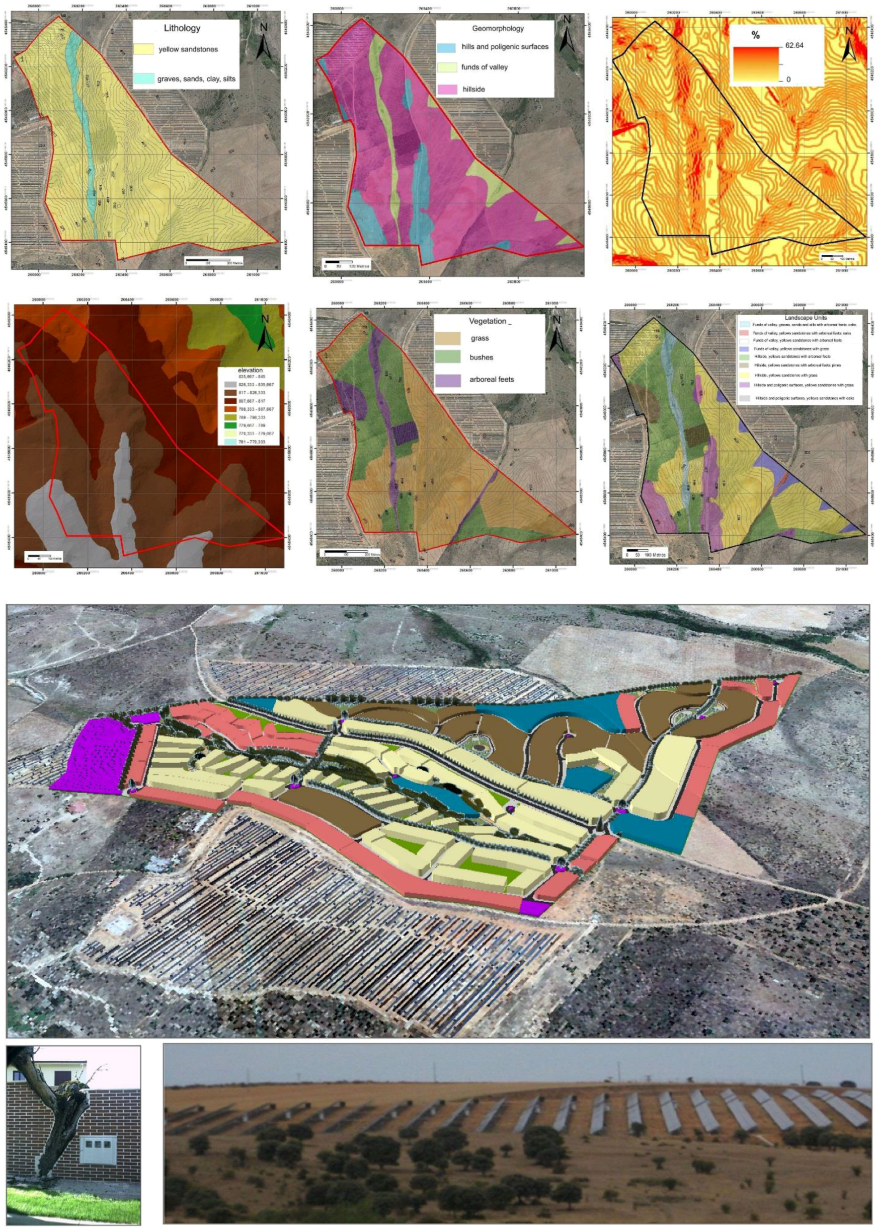
Figure 6) and the ornamental or integration ends that they are assigned to. All the selected species resist the climatic conditions of the zone. To guarantee the survival of each species, they have to be planted at the time of year and with the method specific to each species. In general, the replanting occurs in spring or autumn, as it is inadvisable during winter frost or summer heat. Likewise, a more detailed model of each of the re-vegetated zones is included in the 3D model and map outlining distribution of each species in the different areas. To achieve integration of this new urbanized sector into the environment, the choice of species was dependent on the autochthonous vegetation, avoiding the introduction of native or hybrid varieties that introduce genetic pollution, and of non-native species with invasion properties. Figure 6 outlines the vegetation planted in each zone.
Zone E, or “zone of the grove of evergreen oaks,” has very little slope and blends in with the open zones of the pastures beside it. The zone does not possess a system of irrigation, but it is an area of small watercourses, so the plants will have sufficient water. In addition, the plants have an integral maintenance of 2 years, which will allow the implantation of species of a major size (plants of 1–2 saps). The vegetation is composed of pluriespecific trees and bushes, with a total density of 2.31 feet/m2. The species consist of the following (Table 4):
Table 4. Selected species.
SpeciesSizesNumber of Feet
TreesQuercus ilex rotundifolia18–20 cm perimeter9 feet
BushesGenista scorpius40–60 cm height12 feet
Cytisusscoparius40–60 cm height12 feet
Retama sphaerocarpa40–60 cm height4 feet
These species are naturally present in the zone, which ensures their survival and integration with the environment.
Zone J, or “zone of gardening,” are those zones isolated between the buildings with little slope, without definite orientation and situated next to the road and buildings. The selected species are for decorative and water for irrigation is provided. In this zone, two types of planting are established: inner gardens and outer hedges that act as borders.
Inner gardens: These plots are ornamental in character and are composed of the formations of trees and pluriespecific bushes, with a density of 3.50 feet/m2. Though the zone could have water for irrigation, in these gardens, permanent systems of irrigation are not utilized and rather manual irrigation is performed with a hose connected to a hydrant. There are therefore no further hydrological requirements. Table 5 lists the species.
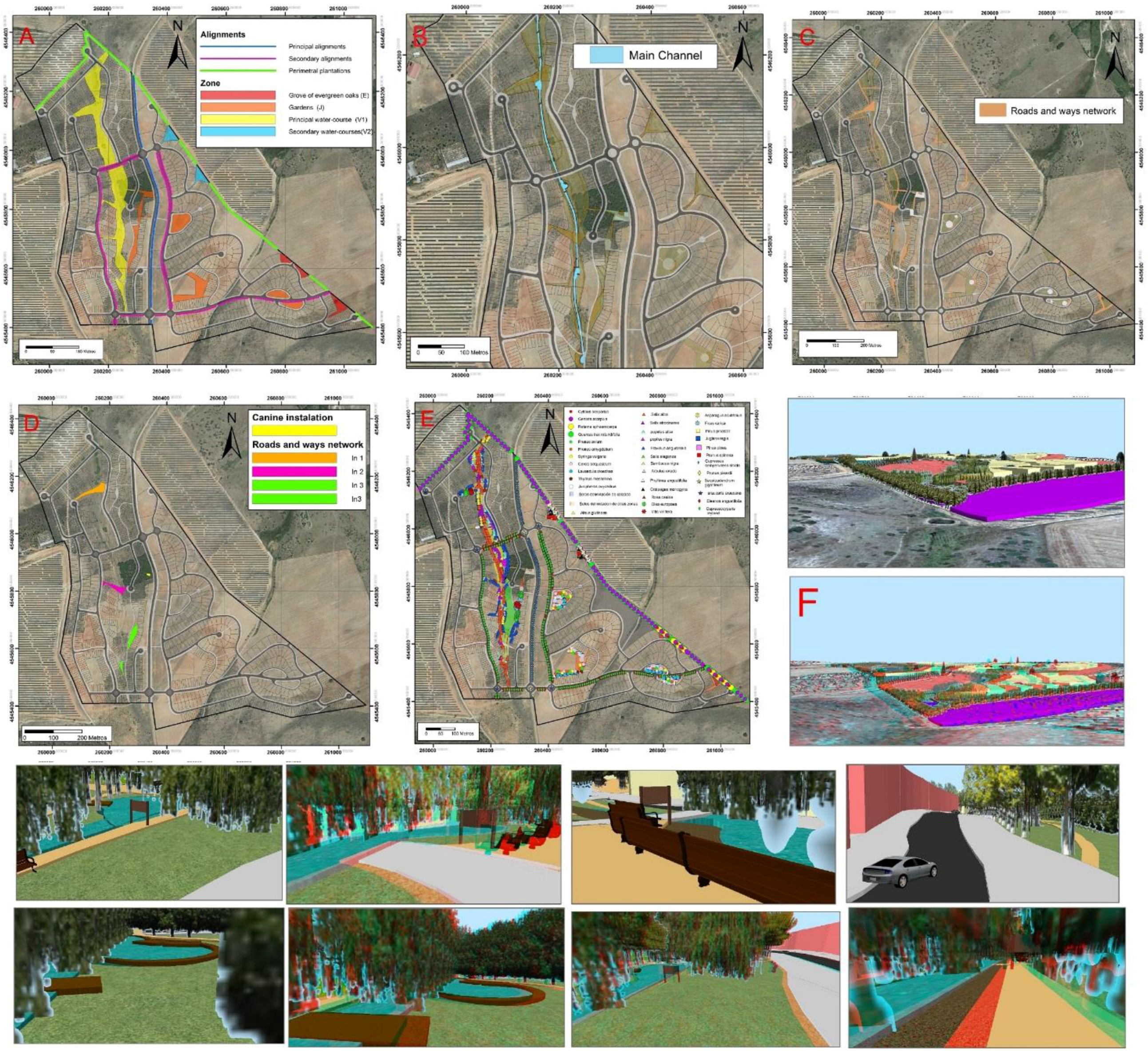
Figure 6. Up: (A) Project plan of environmental and landscape restoration: Avenues and landscape restoration; (B) Main channel; (C) Roads and walkways network; (D) Play structures for children, designated areas for dogs; (E) Vegetable species distribution; (F) anaglyphs of vegetation and 3D restoration: BIM analysis. Down: Virtual modeling near of channel of the decorative furnishings.
Ijgi 05 00002 g006
Table 5. Species selected for inner planting of Zone J.
SpeciesSizeNumber of Feet
TreesPrunus avium14–16 perimeter3 feet
Prunus amygdalus14–16 cm perimeter3 feet
Cercis siliquastrum12–14 cm perimeter3 feet
Syringa vulgaris80–100 cm height4 feet
BushesLavandula stoechas20–40 cm height16 feet
Thymus mastichina20–40 cm height16 feet
Junipherus oxycedrus20–40 cm height8 feet
All these species have ornamental characteristics since they develop flowers and colorful fruits. Some of them, such as Thymus mastichina and Lavandula stoechas, have aromatic properties.
Border hedges: They consist of linear or semi-linear planted bushes and shrubs that act as a boundary between the zone and the road and/or other zones of the sector. Density is of 5 feet/m2, and it possesses a system of drip irrigation which, at the time of species selection had not taken into account the lack of water. Table 6 outlines the planted species.
Table 6. Species selected for planting and border hedges for Zone J.
SpeciesSizeNumber of Feet
Hedges that border the walkwayLigustrum vulgare80–100 cm height5 feet
Hedges that border other zonesMyrtus communis40–60 cm height5 feet
The characteristics of these species make them not only suitable for decorative and/or aromatic purposes, but due to the density of its leaves, also as as an excellent visual screen to block adjacent zones.
Because of its crucial role as the most visible zone both inside and outside of the sector, Zone V1 of the principal watercourse requires its revegetation to integrate with the landscape. The existing vegetation on the riverbanks of the biogeographical zone unaltered by human interference acts as the model.
In this respect, the substrata, placed in a natural way in relation to the watercourses, show differences in granulometry, temperature, salt concentration, dampness, etc., depending on how far each stratum is from the riverbed. They are divided into three different zones: Zone 1 (Soil permanently flooded: It corresponds to the zone that is included in the riverbed; Zone 2 (Soil that remains saturated in water or is humid all year round and that is flooded from time to time); Zone 3 (Soil that presents a partial desiccation during the period of low water, and increases the depth of the groundwater level in comparison to the previous zone).
Based on this, the vegetation is arranged in a series of well-defined bands depending on the species’ needs. In order to recreate the ecosystem before its degradation, the aforementioned bands will be recreated. It is the principal watercourse zone that has been divided into four subfields: Subfield channel, subfield watercourse, subfield meadow and subfield agroforestry.
Plots on the subfield channel: The subfield channel is comprised of a linear zone following the bottom of the current watercourse with a water riverbed in permanent recirculation. The replanted vegetation in this subfield consists of semi-linear rows along the watercourse of helophytics or aquatic vegetable species that need constant water for survival. The subsequent actions performed on the channel are numerous: the shores protect against erosion; they retain the sediments, generate abundant organic matter and detrita necessary for the development of the populations of chironomids and other invertebrates; its plunged roots will be used as refuge and food for fish and tadpoles; its stems source of refuge, food and a place to nest for certain birds etc. Planting should be in dense masses of pluriespecific groupings. Alhough the zone has water available for irrigation, it is not utilized; already the plants have taken the water necessary for its growth and survival directly from the riverbed of the channel. The plantation has a density of 9.50 feet/m2, with the following species as listed in Table 7:
Table 7. Aquatic species selected to be planted in the subfield channel.
SpeciesSizesNumber of Feet
Aquatic plantsTypha latifolia3l6 feet
Phragmites australis3l4 feet
Acorus gramineus3l2 feet
Rorippa nasturtium-aquaticum3l4 feet
Lythrum salicaria3l3 feet
The planting of these species will be realized by bands more or less removed from the channel, depending on the characteristics of each species. The band which is the most removed from the shore will be occupied by Phragmites australis and then in this order: Typha latifolia, Acorus gramineus, Rorippa nasturtium-aquaticum and Lythrum salicaria.
Plots in the subfield watercourse and the subfield meadows: The subfield watercourse is the zone adjacent to the subfield channel. The revegetation in this areafollows, different levels and depends on the water requirement of each species. The species that require a major quantity of water are placed in the zones nearest to the channel and the distances for species that require less water. This is an area with clay soil with flowers on both banks and a typical riverside forest that includes, in descending order, willow trees, an alder grove, a grove of black poplars and ash trees.
Specimens of white Salix, Salix atrocinerea, and Alnus glutinous are arranged in the zones almost next to the channel, since they reduce the risk of flooding. The Elm grove is comprised of specimens of white Populus and Populus nigra and the ash grove constituted by specimens of Fraxinus angustifolia, arranged along the paths that cross the watercourse. As certain species should accompany them, bushes grouped by species (Sálix eleagnos, Sambucus nigra, Arbutus unedo, Phillyrea angustifolia, Crataegus monogyna, and Canine rose) will be planted. The aforementioned species act as a visual and acoustic barrier, as well as windshields.
Meadows are included in the design to fit the climatic species of the zone. The slope of the area shows that the most suitable method is the hydro-sowing. As for the irrigation of the zone, it is worth mentioning that, despite the zone having water available, the plants will develop without it as there will be regular maintenance every two years. Therefore, water availability will not pose a problem, and even very large plants will be able to grow. The density is 3.06 feet/m2, and is composed of the following (Table 8):
Table 8. Species to be planted on the subfield watercourses and subfield meadows.
SpecieSizesNumber of Feet
TreesSalix alba14–16 cm perimeter1 foot
Alnus glutinosa16–18 cm perimeter3 feet
Salix atrocinerea14–16 cm perimeter1 foot
Populus alba3.5–4.0 m height1 foot
Populus nigra3.5–4.0 m height1 foot
Fraxinus angustifolia14–16 cm perimeter2 feet
BushesSalix eleagnos100–120 cm height4 feet
Sambucus nigra80–100 cm height4 feet
Arbutus unedo60–80 cm height4 feet
Phyllirea angustifolia60–80 cm height8 feet
Crataegus monogyna60–80 cm height8 feet
Rosa canina60–80 cm height8 feet
% hydro-sowing
GrasslandsCynodon dactylon30% hydro-sowing
Lolium perenne30% hydro-sowing
Poa bulbosa20% hydro-sowing
Trifolium arvense20% hydro-sowing
All this vegetation placed on the watercourse operates like a protective wall for the channel; it acts as a filter for pollution; a mechanism for sediment retention that reduces erosion; infiltration of the water in the area by retaining the water runoff thus avoiding the formation of puddles.
Agroforestry plots: In the agroforestry subfield, the plots with average slopes served the purpose of education in specific systems of culture. Replanted arboreal and bush plots of an educational character will be organized in monospecific formations for each one of the four cultures. Despite the fact that irrigation had been planned for this area, it will not be used, since there is regular maintenance every two years in order to nurture very large plants that would otherwise not thrive under these conditions. The density will be different in each case. The species selected for replanting are as follows (Table 9):
Table 9. Species for agroforestry plantation.
SpeciesSizesDensity of the Tree or Bush
Olea europeaGreat specimen833 feet/ha
Vitis vinífera60–80 cm height1667 feet/ha
Asparagus acutifolius20–40 cm height3333 feet/ha
Ficus caricaGreat specimen833 feet/ha
Zone V2 or “zone of secondary watercourse” is made up of two watercourses at the exterior edge of the sector, with an average-to-high slope. The species have been selected based on ornamental characteristics and capacity to prevent erosion. Because this zone has a slope that has a moderate incline and that is visible from numerous points inside the sector, it will not be eligible for permanent irrigation. Therefore, the selected species will necessarily not require much water for their survival.
The formations are forests of diverse species, shaped in a pluriespecific-type plot with no particular species assigned to this zone as the goal is to even out the landscape with ornamental correction [17]. The arboreal specimens are Pinus pinea, Pinus pinaster, Juglans regia and Ficus carica planted in rows along the perimeter of the watercourse zone that coincides with the eastern border of the sector. These trees act as an ornamental element; its arboreal high freightage acts as a visual screen, concealing part of the sector, with regard to the external zones. In addition, they block the view of the adjacent solar parks.
The bushes of Crataegus monogyna, Canine Rose and Prunus spinosa also serve decorative purposes for the whole zone of the watercourses. The plants have regular maintenance every two years, meaning that very large species can be planted. The density is 2.37 feet/m2, and includes the following species (Table 10):
Table 10. Species for agroforestry plots in Zone V2.
SpeciesSizesNumber of Feet (Modulate Type of Plot: 8 × 4 m2)
TreesPinus pinea30–35 cm perimeter2 feet
Pinus pinaster30–35 cm perimeter2 feet
Juglans regia25–30 cm perimeter4 feet
Ficus carica25–30 cm perimeter2 feet
BushesCrataegus monogyna60–80 cm height16 feet
Rosa canina60–80 cm height32 feet
Prunus spinosa60–80 cm height16 feet
Avenues: Since they are solely for decoration, the avenues are cork-soled clogs along the road passing through the sector; depending on if the trees line main or side streets, one or more species will be planted. These avenues act as acoustic and visual barriers, separating the different zones inside the sector. As areas with permanent irrigation systems, the species have been chosen without water restrictions. Their planting is linear with a 4 m separation between them, creating a density of 0.25 feet/m2. The species with large roots are placed at the intersection of several streets. The species are as follows (Table 11):
Table 11. Species for the planting of agroforestry avenues.
SpeciesSizes
Principal avenuesCupressus sempervirens16–18 cm perimeter
Prunus pisardiicont. 14–16 cm perimeter
Sequoiadendrum giganteum (roundabouts)Great specimen
Secondary avenuesEleagnos angustifolia16–18 cm perimeter
Cupressocyparis leylandii16–18 perimeter
Araucaria araucana (roundabouts)Great specimen
Perimetral Vegetation: The sector is visible from the north. To conceal the urbanization and to block the view of the nearby solar panels, a vegetable screen is placed along these edges, functioning simultaneously as a visual and acoustic barrier.
The double avenue is Quercus ilex “three-bobbin lace” with a density of 1.25 feet/m2 planted at 1 m intervals, and of bush species with 600 feet/m2 density planted at 0.50 m intervals. The selected species are (Table 12):
Table 12. Species for perimetral planting.
SpeciesSizesNumber of Feet
TreesQuercus ilex rotundifolia18–20 cm perimeter5 feet
BushesGenista scorpius40–60 cm height3 feet
Lavandula stoechas20–40 cm height3 feet
The plots of broom and lavender are arranged linearly on a ridge of land chosen for remodeling. Both species are perennial and the barrier will be effective both in winter and summer.

4. Conclusions

Applying Building Information Modeling (BIM) to the landscape for planning environmental restoration ensures the evolution of a rustic rural zone into a sustainable urban sector. Because the integrated technologies of remote sensing and GIS (ArcGis 10.2) allow for visualization and modeling by simulating the different zones of the construction project, it becomes possible to integrate the residential areas and infrastructure with the natural environment. A series of measures for the adjustment of the urban development’s preliminary design to better conform to the physical environment promises a constructive, respectful design that blends in with the lithology, geomorphology, etc. of the landscape, thereby improving the intrinsic and extrinsic landscape of the natural environment. The following conclusions can be made:
  • GIS with remote sensing provides detailed analysis of the lithological and geomorphological factors guides the remodeling of the area’s surface, thereby integrating, smoothing and harmonizing the forms, chromatism, and size of the slopes.
  • The interaction between the cartographic indirect methods of the components of the landscape and direct methods determining the elements of the landscape (forms, sizes, scales …), from points of observation and fieldworks constitutes a very effective methodology which is used to determine the different landscape units and its geospacial distribution. The emplacement of the houses has been designed so that they are all separated by green spaces and vehicle access between them is minimized.
  • The calculation of the visual basins with GIS technologies determines with great precision the zones of perceptual affection of the different units of work, buildings and own infrastructures of the urbanization. It decides the scope of the different urban development pressures in every sector of the territory and for every type of soil uses.
  • The utilization of digital models of the area, with its very detailed spatial resolution, facilitates planning of the modifications based on predicted damage during the urban development phase.
  • The simulation of the different 3D models generated with scripts of ArcGis 10.2, contributes different symbols (spread vegetables, housing types, green spaces, roads, urban tools …), and outlines different attributes (height, thickness of glass ….), thereby allowing early and virtual forms that predict lines of visibility from the different points of interest.
  • The replanting of the different plots for screening in the external perimeter and along the different zones conceals human activities and provides green spaces.
  • The integration of the water corridors (natural watercourses) in the sustainable design of the urban development planning helps to heighten, improve and stabilize the water positively, creating perceptions of major naturalness, promoting re-greening efforts and synergizing the urban development with the environment.
  • Well-executed landscape restoration allows for the creation of outdoor spaces that include recreational facilities (playgrounds, dog parks, etc.), where the local inhabitants can enjoy the nature and landscape that surround them, which ultimately contributes to improvement in the population’s quality of life.

Acknowledgments

Ministry of Economy and Competitiveness: BTE, CGL2012-33430/BTE and CGL2012-37581/BTE.

Author Contributions

All the authors contributed equally to this work.

Conflicts of Interest

The authors declare no conflict of interest.

References

  1. Dunn, M. Landscape Evaluation Techniques: An Appraisal and Review of the Literature; Centre of Urban and Regional Studies, University of Birminghan: Birminghan, UK, 1974. [Google Scholar]
  2. Baby, S.; Nagyvaradi, L.; Balassa, B. Choropleth mapping and interpolation technique to analyze the demographic influence on Kuwait’s coastal morphological landscape. Environ. Eng. Manag. J. 2013, in press. [Google Scholar]
  3. Baundry, J.; Burel, F. Ecología del Paisaje: Concepto, Métodos y Aplicaciones; Mundi-Prensa: Madrid, Spain, 2002. [Google Scholar]
  4. Bevins, R.E.; Ixer, R.A.; Webb, P.C.; Watson, J.S. Provenancing the rhyolitic and dacitic components of the Stonehenge landscape bluestone lithology: New petrographical and geochemical evidence. J. Archaeol. Sci. 2012, 39, 1005–1019. [Google Scholar] [CrossRef]
  5. Instrumento de ratificación del Convenio Europeo del Paisaje. Madrid, Spain, 2008. Available online: https://www.boe.es/buscar/doc.php?id=BOE-A-2008-1899 (accessed on 25 November 2015).
  6. Bolós, M. Manual de Ciencia del Paisaje: Teoría, Métodos y Aplicaciones; Masson: Barcelona, Spain, 1992. [Google Scholar]
  7. Bronnikova, M.; Panin, A.; Uspenskaya, O.; Fuzeina, Y.; Turova, I. Late Pleistocene-Holocene environmental changes in ultra-continental subarid permafrost-affected landscapes of the Terekhol’Basin, South Siberia. Catena 2014, 112, 99–111. [Google Scholar] [CrossRef]
  8. Cifuentes, P. La Calidad Visual de Unidades Territoriales. Aplicación al Valle del Río Tiétar. Tesis Doctoral. E.T.S. de Ing. de Montes; Universidad Politécnica: Madrid, Spain, 1979. [Google Scholar]
  9. European Landscape Convention (2000). Florence, Italy, 20 October 2000. Available online: https://rm.coe.int/CoERMPublicCommonSearchServices/DisplayDCTMContent?documentId=09000016800805ce (accessed on 22 November 2015).
  10. Franco-Magalhaes, A.O.B.; Cuglieri, M.A.A.; Hackspacher, P.C.; Saad, A.R. Long-term landscape evolution and post-rift reactivation in the southeastern Brazilian passive continental margin: Taubaté basin. Int. J. Earth. Sci. (Geol. Rundsch) 2014, 103, 441–453. [Google Scholar] [CrossRef]
  11. García-Quintana, A.; Martín-Duque, J.F.; González-Martín, J.A.; García-Hidalgo, J.F.; Pedraza, J.; Herranz, P.; Rincón, R.; Estévez, H. Geology and rural landscapes in Central Spain (Guadalajara, Castilla-La Mancha). Environ. Geol. 2005, 47, 782–794. [Google Scholar] [CrossRef]
  12. Hou, Y.; Burkhard, B.; Müller, F. Uncertainties in landscape analysis and ecosystem service assessment. J. Environ. Manag. 2013, 127, S117–S131. [Google Scholar]
  13. Hurni, L.; Veronesi, F. A GIS tool to increase the visual quality of relief shading by automatically changing the light direction. Comput. Geosci. 2015, 74, 121–127. [Google Scholar]
  14. Directive 2007/2/EC of the European Parliament and of the Council of 14 March 2007 Establishing an Infrastructure for Spatial Information in the European Community (INSPIRE). Available online: http://eur-lex.europa.eu/legal-content/EN/ALL/?uri=CELEX:32007L0002 (accessed on 30 November 2015).
  15. Jefferson, A.; Grant, G.E.; Lewis, S.L.; Lancaster, S.T. Coevolution of hydrology and topography on a basalt landscape in the Oregon Cascade Range, USA. Earth Surf. Process. Landf. 2010, 35, 803–816. [Google Scholar] [CrossRef]
  16. La Rosa, D.; Martinico, F. Assesment of hazards and risks for landscape protection planning in Sicily. J. Environ. Manag. 2013, 127, 155–167. [Google Scholar] [CrossRef] [PubMed]
  17. La Rosa, D.; Privitera, R.; Martinico, F.; La Greca, P. Measures of safeguard and rehabilitation for landscape protection planning: A qualitative approach based on diversity indicators. J. Environ. Manag. 2013, 127, 573–583. [Google Scholar] [CrossRef] [PubMed]
  18. Martínez-Graña, A.M.; Goy, J.L.; Zazo, C.Z. Dominant soil map in “Las Batuecas-Sierra de Francia” and “Quilamas” nature parks (Central System, Salamanca, Spain). J. Maps 2015, 11, 371–379. [Google Scholar] [CrossRef]
  19. Martínez-Graña, A.M.; Goy, J.L.; Zazo, C. Water and wind erosion risk in natural parks. A case study in “Las Batuecas-Sierra de Francia” and “Quilamas” protected parks (Central System, Spain). Int. J. Environ. Res. 2014, 8, 61–68. [Google Scholar]
  20. Martínez-Graña, A.M.; Goy, J.L.; de Bustamante, I.; Zazo, C. Characterisation of environmental impact on resources, using strategic assessment of environmental impact and management of natural spaces of “Las Batuecas-Sierra de Francia” and “Quilamas” (Salamanca, Spain). Environ. Earth Sci. 2014, 71, 39–51. [Google Scholar] [CrossRef]
  21. Martínez-Graña, A.M.; Goy, J.L.; Zazo, C. Cartographic-environmental analysis of the landscape in natural protected parks for his management using GIS. Application to the natural parks of the “Las Batuecas-Sierra de Francia” and “Quilamas” (Central System, Spain). J. Geogr. Inf. 2013, 5, 54–68. [Google Scholar] [CrossRef]
  22. Martínez-Graña, A.M.; Goy, J.L.; Zazo, C.; Yenes, M. Engineering geology maps for planning and management of natural parks: “Las batuecas-sierra de francia” and “quilamas” (Central Spanish system, Salamanca, Spain). Geosciences 2013, 3, 46–62. [Google Scholar] [CrossRef]
  23. Martínez Vega, J.; Martin, M.P.; Calcerrada, R. Valoración del paisaje en la zona de especial protección de aves carrizales y sotos de Aranjuez (Comunidad de Madrid). Rev. Geofocus 2003, 3, 1–21. [Google Scholar]
  24. Masnavi, M.R. Environmental sustainability and ecological complexity: Developing an integrated approach to analyse the environment and landscape potentials to promote sustainable development. Int. J. Environ. Res. 2013, 7, 995–1006. [Google Scholar]
  25. Otero Pastor, I.; Casermeiro Martínez, M.A.; Ezquerra Canalejo, A.; Esparcia Mariño, P. Landscape evaluation: Comparison of evaluation methods in a region of Spain. J. Environ. Manag. 2007, 85, 204–214. [Google Scholar] [CrossRef] [PubMed]
  26. Ramos, A. Visual Landscape Evolution. A grid technique. Landsc. Plan. 1976, 3, 67–88. [Google Scholar] [CrossRef]
  27. Rink, K.; Scheuermann, G.; Kolditz, O. Visualisation in environmental sciences. Environ. Earth Sci. 2014, 72, 3749–3751. [Google Scholar] [CrossRef]
  28. Shiliang, D.; Xiao, R.; Delong, L.; Hu, Y. impacts of transportation routes on landscape diversity: a comparison of different route types and their combined effects. Environ. Manag. 2013. [Google Scholar] [CrossRef]
  29. Shulin, L.; Wang, T. Aeolian processes and landscape change under human disturbances on the sonid grassland of inner Mongolian Plateau, northern China. Environ. Earth Sci. 2014, 71, 2399–2407. [Google Scholar]
  30. Taylor Perron, J.; Fagherazzi, S. The legacy of initial conditions in landscape evolution. Earth Surf. Process. Landf. 2012, 37, 52–63. [Google Scholar] [CrossRef]

