Article

Laser Scanning and Data Integration for Three-Dimensional Digital Recording of Complex Historical Structures: The Case of Mevlana Museum

1
Department of Geomatics, Engineering Faculty, Selcuk University, Selcuklu, Konya 42075, Turkey
2
Department of Architecture, Built Environment and Construction Engineering, Politecnico di Milano, Milano 20132, Italy
*
Author to whom correspondence should be addressed.
ISPRS Int. J. Geo-Inf. 2016, 5(2), 18; https://0-doi-org.brum.beds.ac.uk/10.3390/ijgi5020018
Submission received: 3 November 2015 / Revised: 12 January 2016 / Accepted: 25 January 2016 / Published: 18 February 2016

Abstract

:
Terrestrial laser scanning method is widely used in three-dimensional (3-D) modeling projects. Nevertheless it usually requires measurement data from other sources for full measurement of the shapes. In this study a 3-D model of the historical Mevlana Museum (Mevlana Mausoleum) in Konya, Turkey was created using state-of-the art measurement techniques. The building was measured by terrestrial laser scanner (TLS). In addition, some shapes of the indoor area were measured by a time-of-flight camera. Thus, a 3-D model of the building was created by combining datasets of all measurements. The point cloud model was created with 2.3 cm and 2.4 cm accuracy for outdoor and indoor measurements, and then it was registered to a georeferenced system. In addition a 3-D virtual model was created by mapping the texture on a mesh derived from the point cloud.

1. Introduction

Cultural assets are extremely important structures to be transferred to next generations as the common heritage of the humanity [1]. Therefore, their documentation is an important facet of this process. In particular, recording their shape, dimensions, colors, and semantics may allow architects to restore their original forms and rebuild them when they would be destroyed [2]. Any kinds of geometric information about the object (volume, length, location, digital elevation model, cross-sections) can be retrieved from three-dimensional (3-D) digital models [3,4]. 3-D modeling has been practiced for many aims such as virtual reality, heritage building information model (HBIM) applications [5,6], documentation of historical structures, physical replication of artefacts [7], among others. It requires collecting and integrating high-density spatial data from the object surface [8]. In the last decade, with the impressive development of digital photogrammetric techniques, scanning and 3-D imaging sensors, 3-D spatial data of architectural objects can be measured very quickly and precisely. Plenty of literature has been published where different approaches are analyzed and compared [3,9,10,11,12]. In reality, in many cases their integration in the optimal solution, being imaging and scanning techniques, are quite complementary [8]. Terrestrial laser scanning should be preferred when the target is a complex structure that is difficult to model by means of geometric primitives [13]. It is also increasingly used for digitization of cultural heritage [10]. Many studies about heritage documentation projects have been made by using laser scanning technique singly, or together with image based techniques [3,14,15]. Due to object size, shape, and occlusions, it is usually necessary to use multiple scans from different locations to cover every surface [10]. Multiple scan stations can be integrated in a relatively easy way by means of consolidated registration techniques [16,17,18,19]. On the other hand, photogrammetry is more suitable for modeling those surfaces that can be decomposed in regular shapes, even though the development of dense matching techniques [20] gave the opportunity to obtain results comparable to terrestrial laser scanners (TLS) in the reconstruction of free-form objects [21,22]. Photogrammetry also has the advantage of being operated by light sensors that can be carried onboard unmanned aerial vehicle (UAV) systems [23]; such platforms are useful for data acquisition over roofs and other non-accessible places. Very often a camera is integrated into a TLS instrument to allow the contemporary recording of 3-D shape and color information.
The emerging technology for 3-D measurement is range imaging [24], which can be operated by means of time-of-flight (ToF) cameras. Such sensors can instantly measure a set of 3-D points (point cloud) which represents the geometry of the imaged area. Due to the small size and weight, and the capability of directly recording 3-D information, ToF cameras have a great potential to devise a wide range of applications in the future. The measurement process is based on recording the response of a modulated laser light emitted by the sensor itself. [25] and [26] exploited a ToF camera and image-based modeling for 3-D visualization of cultural heritage. On the other hand, influences of the measuring direction inclination and material types on distance measurement accuracy have been investigated by [27].
In this study, a 3-D digital model of Mevlana Museum (Konya, Turkey) was created by combining TLS and ToF camera data. The outside of the building were solely measured by laser scanner, while indoor details were measured by using both techniques. Virtual models and orthophoto images were created for important details by texturing image onto the point cloud, after creating a mesh surface. Thus, the performance of ToF cameras for cultural heritage (CH) documentation has been evaluated in terms of possible new applications. In addition, the accuracy of the 3-D point cloud model was analyzed.

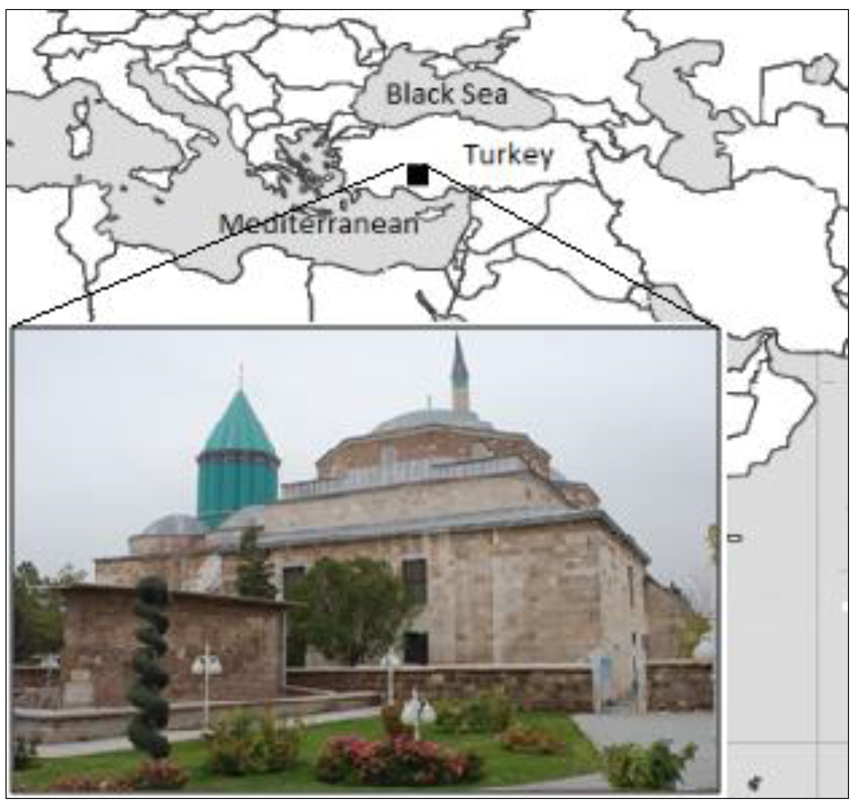
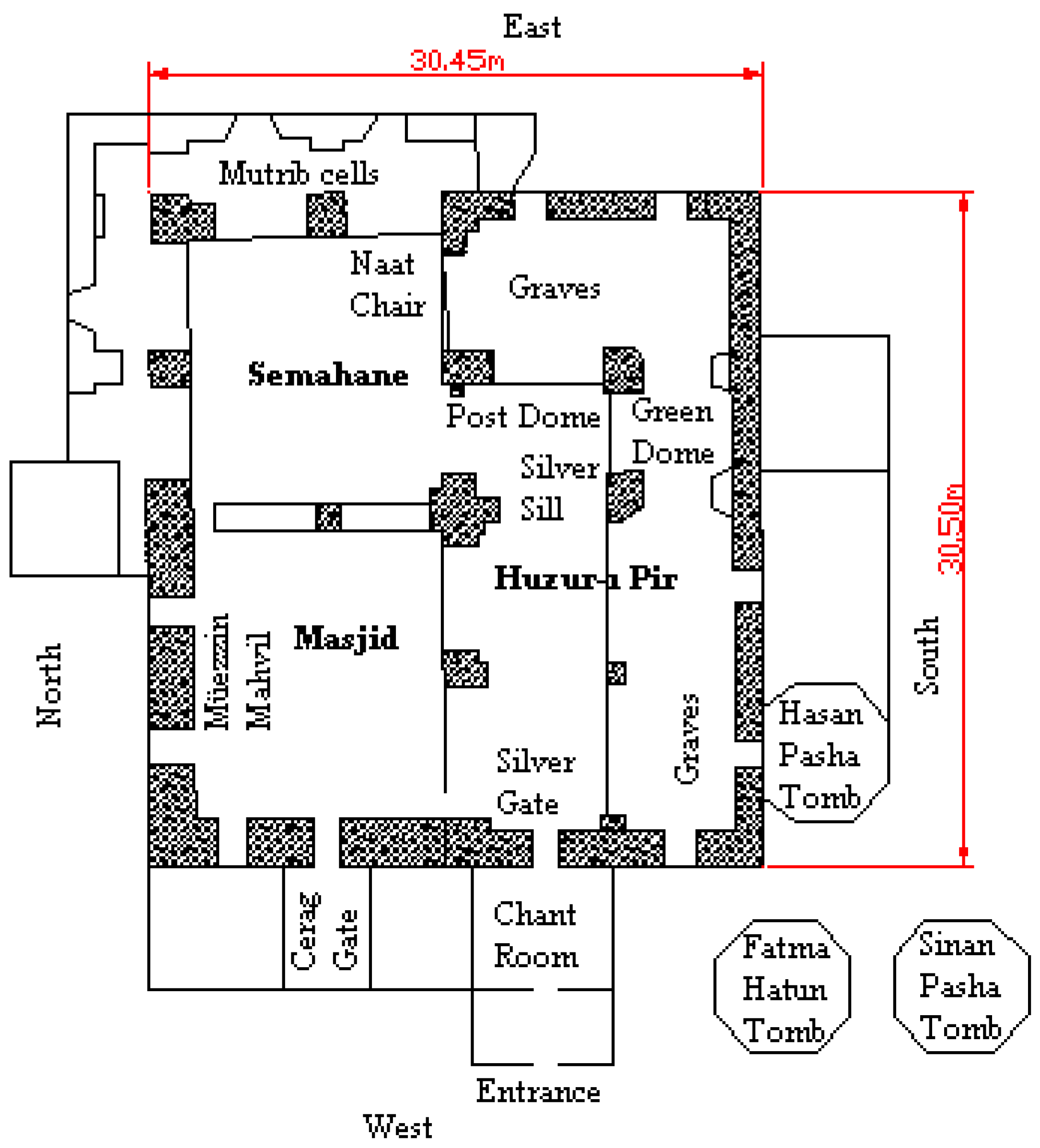
2. The Case Study: Mevlana Museum

Mevlana Museum is located in the city center of Konya, Turkey (Figure 1). The museum was setup around the mausoleum of Mevlana Jalaluddin Rumi, which was built during the Seljuq period (13th century). The location of “Dervish Lodge” which is currently used as a museum used to be a rose garden of the Palace of the Seljuq. “Dervish Lodge” was gifted by Sultan Alaeddin Keykubat to Sultanul-Ulema Bahaeddin Veled, the father of Mevlana. The mausoleum where the Green Dome (Kubbe-i Hadra) is located was built with the permission of the son of Mevlana, Sultan Veled, by architect Tebrizli Bedrettin in 1274 after the death of Mevlana. From that time, the construction activities continued up to the end of the 19th century [28].
The “Mevlevi Dervish Lodge” and the mausoleum began to serve as a museum under the name “Konya Asar-ı Atika Museum” in 1926. In 1954 the exhibition and arrangement of the museum was revised and the name of the museum was changed to the Mevlana Museum [28]. The section where the mausoleum is located is 30.5 m × 30.5 m in size and the courtyard is 68 m × 84 m in size.
The courtyard of the museum is entered from Dervisan Gate. There are “Dervish Rooms” along the north and west sides of the courtyard. The south side next to the Matbah and the Hurrem Pasha Mausoleum ends with the Hamusan Gate opened to the Ucler Cemetery. In the east of the courtyard there is the main building where Semahane, Masjid, and the graves of Mevlana and his family members are located. The covered fountain and “Seb-i Arus” pool give a novel touch to the courtyard [28].
The entrance to the mausoleum of Hazreti Mevlana is from the Chant Room (Figure 2). The Chant Room is a dome-covered square place. Next to it, beyond the silver gate there is the mausoleum hall (Huzur-ı Pir) to enter, which is roofed by three small domes. The third dome is called Post Dome and it adjoins the Green Dome in the north. The mausoleum hall is surrounded by a high wall in the east, south, and north. The graves of Mevlana and his son, Sultan Veled, are located under the Green Dome [28].
The Semahane along with Masjid was built by Suleiman the Magnificent in XVI century. The naat chair in Semahane, the Mutrib room where musicians lived, and the gathering places belonging to men and women are preserved in their original state.
The Masjid is entered from the Cerag Gate. Also, there are transitions with a small door from Semahane and Huzur-ı Pir sections where there are the graves. In this section, the Muezzin Mahvil and the Mesnevihan chair are kept in their original form.

3. Materials and Methods

Terrestrial laser scanning (TLS) surveying has been used to creating 3-D models of historical buildings. The main steps of the 3-D modeling process with this technique are point cloud registration, texture mapping, and geo-referencing, which necessitates connection with the other related spatial data. The high-resolution spatial data measured, like the point cloud, depicts the shape of the object. In addition, the texture data should be mapped to the point cloud, after meshing, for the real visualization of the object. Terrestrial laser scanners are used for measurement of the outside and inside details. In addition, in the indoor area, complex details that cannot be completely measured with TLS were imaged by ToF imaging, which is an affordable tool to accomplish this task. The flowchart in Figure 3 shows the method followed in the measuring and creation of the 3-D model of the museum.

3.1. Terrestrial Laser Scanning

In this study, laser scanning measurements were carried out with Optech ILRIS-3D laser scanner device. This device can measure 2500 points in a second using direct ToF method. The range measurement accuracy is 7 mm at 100 m. Its minimum sampling step (point-to-point spacing) is 0.001146° (20 μrad). Beam divergence is 0.009740° (170 μrad). It records color data for the measured points on the basis of the integrated camera (six megapixel). The maximum measurement range of the instrument is 1300 m. It makes panoramic measurements at 220° vertical and 360° horizontal field-of-view, respectively [29].
The ability to capture centimeter accuracy data at high resolution and the rapid response capability afforded by TLS makes it the ideal tool for quantitative measurement of architectural buildings. TLS may use direct ToF, phase-shift, and triangulation methods to measure the distance from the instrument to the object points [30]. The maximum measurement range of phase-shift and time-of-flight laser scanners can reach, approximately, five hundred to a few thousand meters away, respectively. They have been used for modeling of buildings and outdoor objects [31,32,33]. The maximum range of the instruments based on the triangulation method is about eight meters away. Thus, it has been generally used for 3-D modeling of small objects.
Laser scanning data are a benefit to creating 3D drawing, virtual models, and orthophoto images of architectural structures. One of the limitations of laser scanning is the measurement from ground-based static instrument stations. Thus, multiple scans are frequently required in order to model large objects. In this regards, all of the point clouds should be registered into a common reference system. Another limitation of the laser scanning is the equipment cost, which may reach several tens of thousands of U.S. dollars.

3.2. Time-of-Flight (ToF) Imaging

A SwissRanger® SR4000 camera was used in this study [34,35]. It has size 65 mm × 65 mm × 68 mm and weight of 470 g. The imaging sensor has size 144 × 176 pixels and the measurement error is 1 cm on its maximum measurement range of 5 m [36]. The SR4000 camera records 50 frames per second (fps). The coordinates (xyz), the amplitude, and confidence values are recorded into the measurement files. The origin of the coordinates is the optical axis and overlaps the camera frontal plane (Figure 4). All frames acquired sequentially are recorded in separate measurement files. In the case of the ToF camera is kept in the stationary position during data acquisition, some differences usually occur between the measurements (frames) recorded from the same scene. Such departures are due to various systematic errors that need to be modeled, and to random noise. Therefore, if more than one measurement of the same image area is recorded, an average image file can be generated in order to minimize noise. According to the results obtained by other researchers, a number between 10 and 30 frames is generally adequate to create 3-D models [37]. The self-calibration of ToF cameras has been performed with various techniques [38]. The effect of distortion error in the coordinate measurement of the SR4000 camera was corrected by using the factory settings. The output of the ToF camera is a point cloud. On the other hand, the measurement can also be made in motion by handling the ToF camera by registering different 3-D scenes into a single coordinate system [39].
ToF imaging techniques can be used in several domains. Driver assistance, interactive screen, and biomedical applications are reported in [40]. Even though these processes can be carried out by using laser scanning or photogrammetry, the use of a ToF camera makes data acquisition faster and economically sustainable. Hussmann et al. [34] compared photogrammetry and a ToF camera, in terms of field of view, conjugate point detection, and measurement. These two methods were examined in the automotive industry for driver assistance, accident prevention, automatic brakes, and for determining the movements on the road. The ToF camera was found superior to the photogrammetric method. Boehm and Pattinson [41] investigated the exterior orientation of ToF point clouds in relation to a given reference TLS point cloud. In addition, ToF imaging has been used for object modeling [37,42,43], structural deflection measurement [44,45], and human motion detection [46]. Moreover, mobile measurement was carried out by ToF imaging for detecting the route of moving robots [39] or mapping indoor environment [47].

4. Data Acquisition Process

4.1. Measurement of the Outside Surfaces

The outside surfaces of the museum were measured by using a Optech ILRIS-3D terrestrial laser scanner (see Subsection 3.1). The selected spatial sampling resolution was about 1.5 cm on the object walls, ceilings, and floors. The doors, due to fine details and embellishments, were measured with a sampling spatial resolution of 1 cm and 3 mm, respectively. The sampling resolution on the roof (outer surface) was 3 cm. Each scan was overlapped with others for at least 30% to help co-registration. The laser scanning measurements of the outside surfaces of the museum were carried out from a distance of approximately 25 m. The roof was measured from the minarets of Selimiye Mosque located near the museum, and the measuring distance was approximately 60 m. The sections of the roof that cannot be measured from there were measured by climbing onto the roof. A total number of 110 laser scanning stations were set up for measuring the outside surfaces of the museum (Figure 5). Totally, 2,980,000 laser points were recorded.

4.2. Measurement of the Indoor Environment

The indoor areas of the museum were measured by TLS with a spatial sampling resolution of 1 cm. The same instrument Optech ILRIS-3D was applied here. Details were measured with a sampling resolution of 3 mm. The indoor environment was recorded from 72 stations and 5,835,000 points were measured. As the administration of the museum did not allow scanning of the place where the tomb of Mevlana is located, the measurement of the ceiling of this section could not be carried out. With the exception of this area, a SR4000 ToF camera was used to record any small details inside the museum. The light weight and the chance to handle the ToF camera helped the acquisition of details located in positions difficult to cover with TLS. Some details in Huzur-ı Pir and Masjid were measured by the SR4000 camera from different stations in order to overlap. The point cloud registration and the integration of TLS and ToF data are illustrated in Section 5.

4.3. Image Acquisition

Photorealistic texture mapping was needed to create a virtual-reality (VR) model of the museum [48]. Due to the low resolution of imaging sensors embedded in the adopted TLS and ToF camera, independent images were acquired for the mere purpose of photo-texturing.
A single-lens reflex (SLR) Nikon D80 camera (pixel array 3872 × 2592, pixel size 6.1 µm, focal length 24 mm), which had been calibrated beforehand [49], was used for image acquisition. The details to be textured were photographed from a frontal position, in order to mitigate perspective distortions and irregularity in color and intensity. The brightness of the image depends upon the light source and camera position. Thus, the images should be taken from proper positions [50,51].

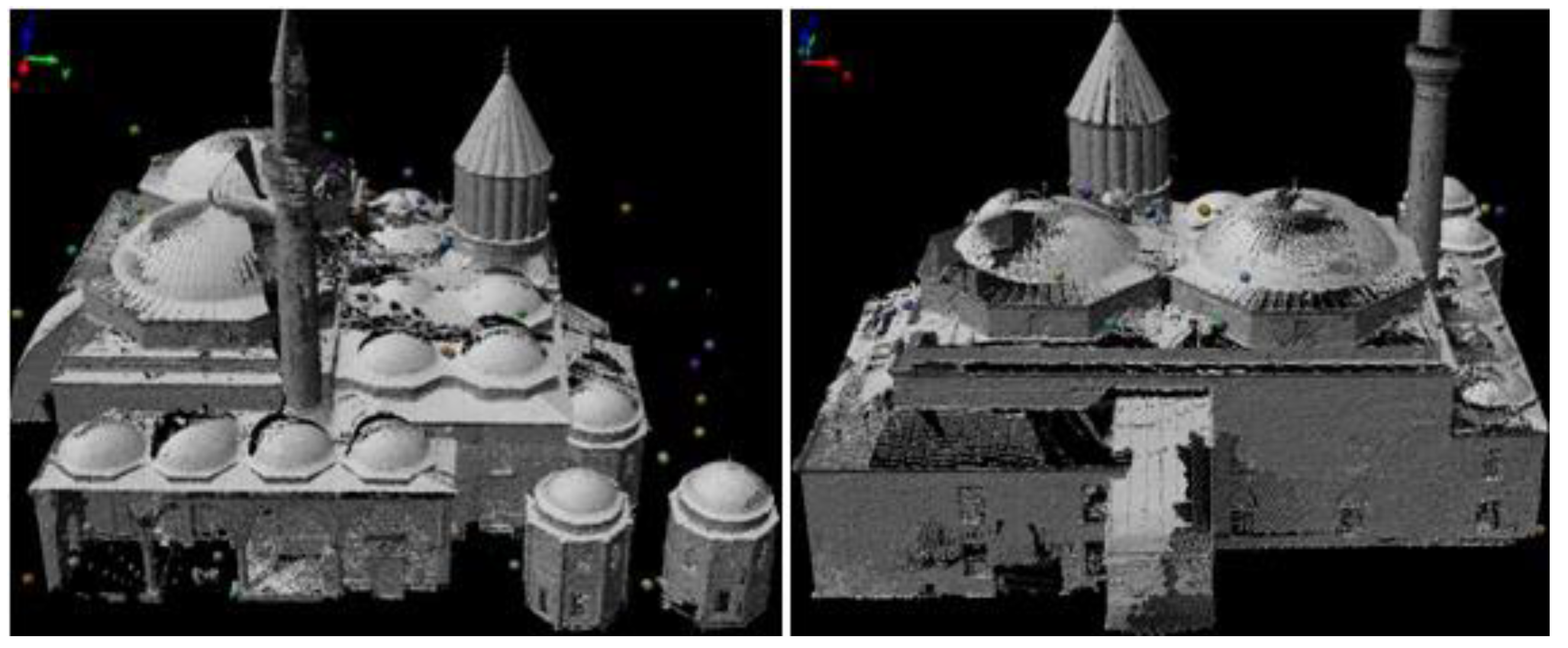
5. Creating 3D Point Cloud Model

5.1. Registration of Laser Scanner Measurements

The registration of the laser scanner point clouds and the creation and editing of the triangulated (mesh) surface was undertaken with PolyWorks® software [52]. First of all, the measurement files recorded from TLS were converted to the PIF file format with Optech Parser (ver.4.2.7.2) software.
The registration of the point clouds was operated in PolyWorks® IMAlign® module with the Iterative Closest Point (ICP) method (see Pomerleau et al. [53] for a review). The point cloud featuring the largest overlap with respect to other scans was selected as a reference. Scans that directly overlapped this were registered to its coordinate system. After the registration of this group of scans to the reference, the process continued up to include all remaining scans.
In order to apply ICP, initial registration parameters were obtained from the manual measurement of at least three common points (from natural details such as corners, edges, or distinctive details). Then, the fine registration was applied with the ICP method. After registering all scans in this way, the global registration was accomplished to minimize the cumulative errors originated from consecutive registrations. In the global registration, the registration of all the scans with respect to the reference data set were performed simultaneously. The maximum root mean square error (RMSE) of scan registrations after the global registration was 2.5 cm. In the first stage, TLS point clouds of outdoor (Figure 6) and indoor (Figure 7) environments were independently registered. Then, these were combined with the georeferencing stage that is illustrated in Section 6.

5.2. Registration of ToF Camera Point Clouds

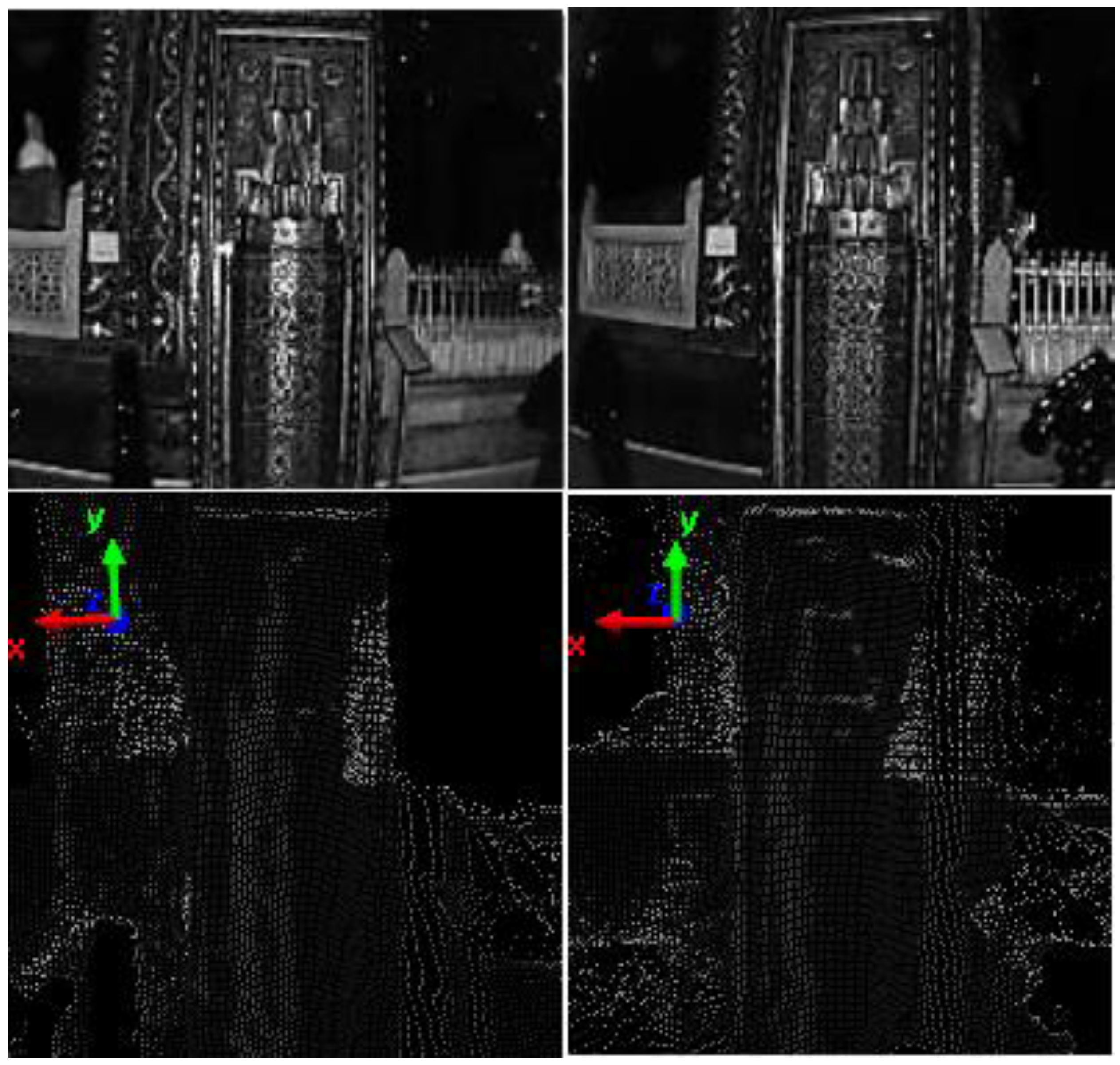
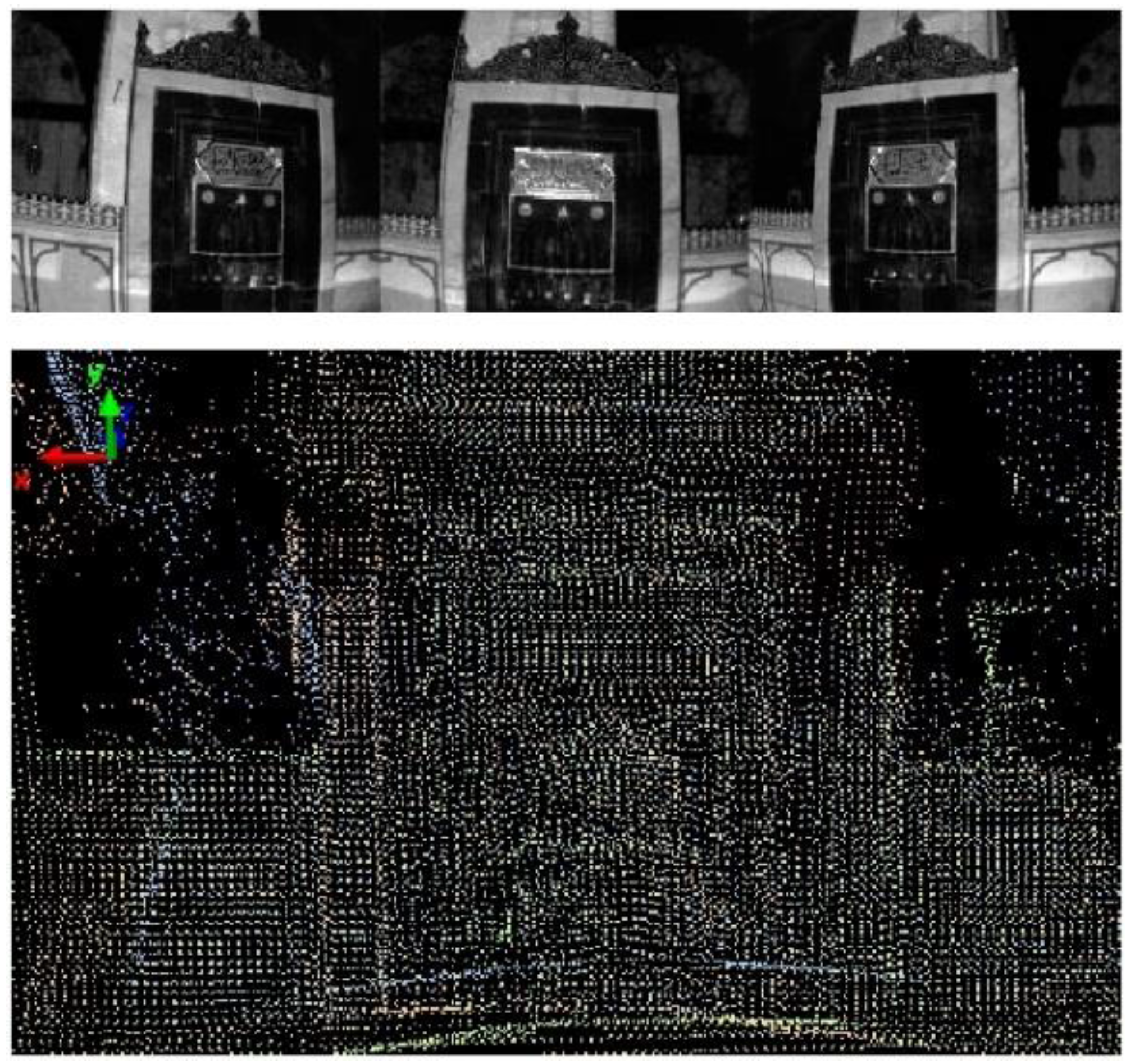
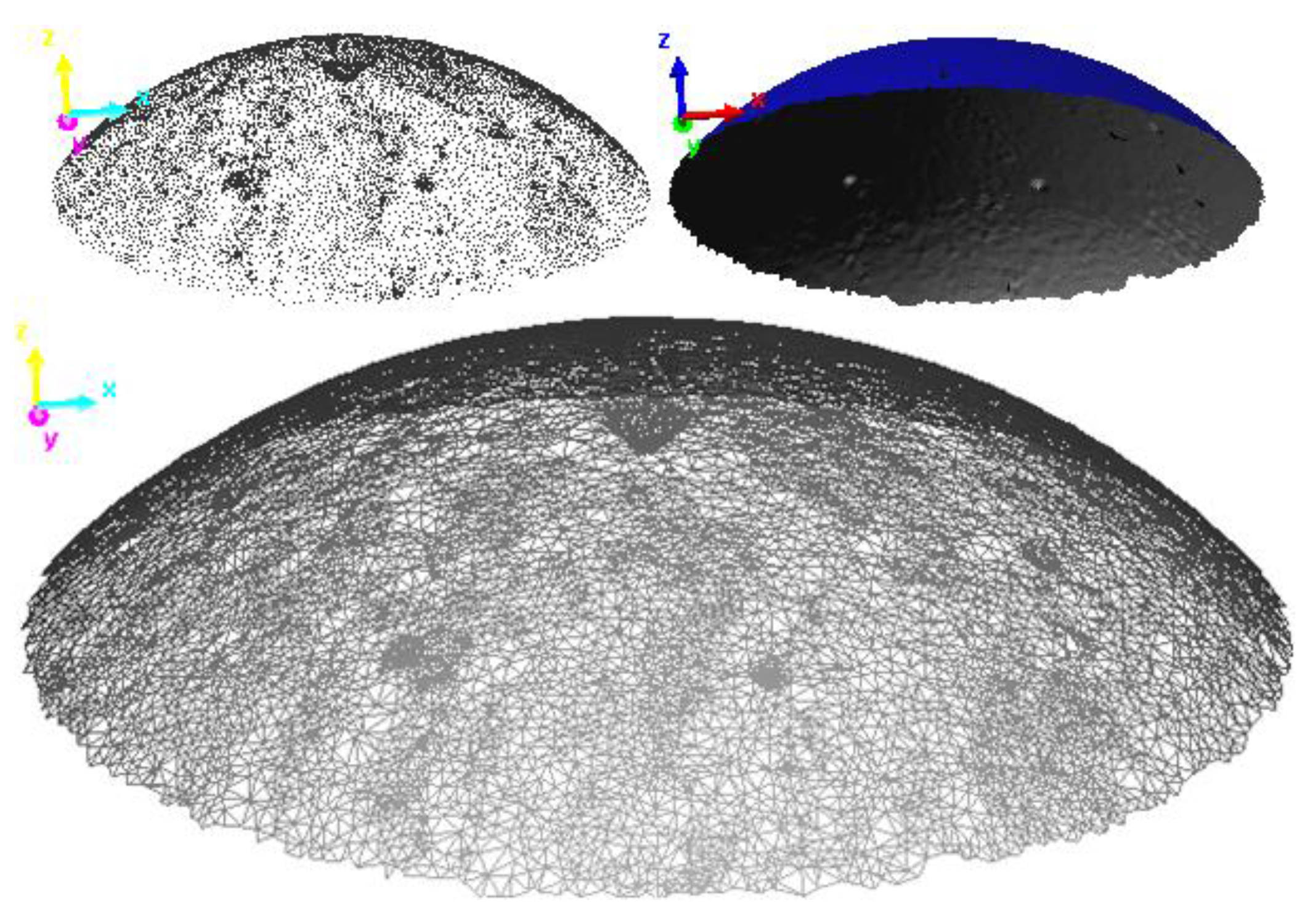
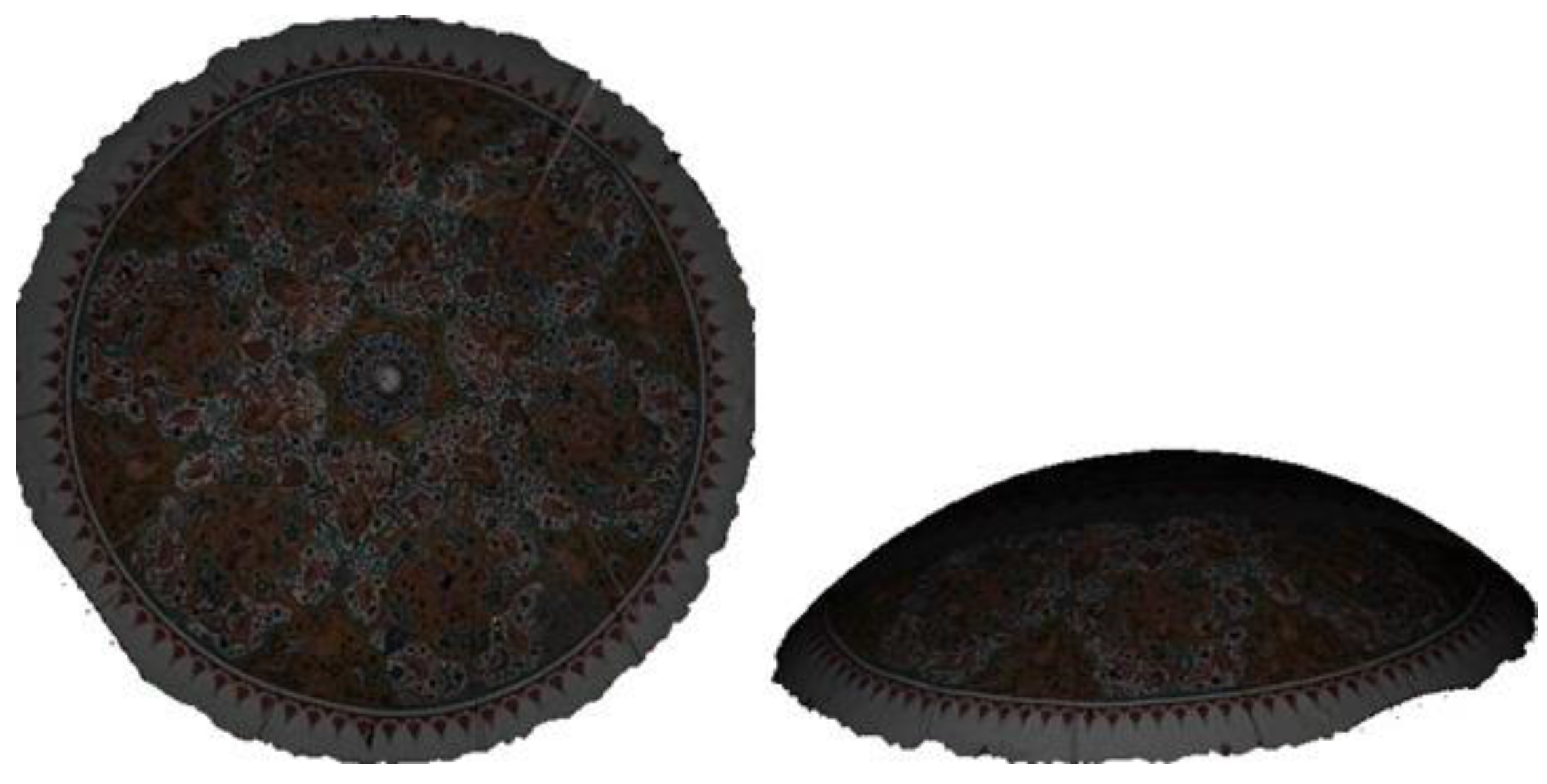
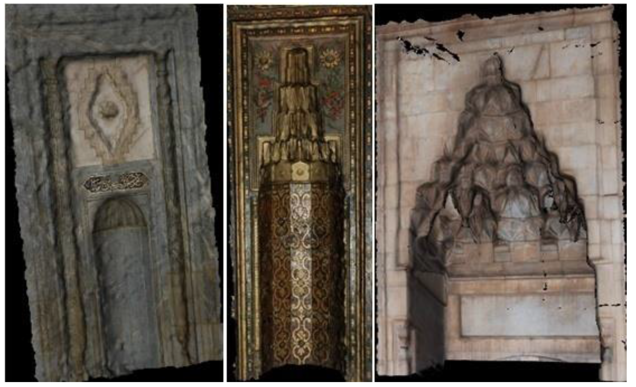
5.2.1. Case 1: Measurement of the Mihrab in Huzur-ı Pir Section

In Huzur-ı Pir section, the Mihrab next to the silver sill was measured using a SR4000 ToF camera. Fifty frames were recorded from a distance of 4.5 m at two stations. This measurement distance resulted in a mean object sampling spatial resolution of 2.0 cm (angular resolution 0.24 degrees). The integration time was set to 30 (unit is arbitrary) and the modulation frequency was set to 15 MHz. The average measurement files (Figure 8) of the raw frames from both stations were created using Matlab® code. ToF point clouds have more mistaken points, especially close to the edge of the frame. Thus, the parts that have error-prone points on the edge were removed from the point clouds. Then, the second point cloud was registered to the coordinate system of the first (reference) point cloud with 1.9 cm standard deviation by using ICP.

5.2.2. Case 2: Measurement of Mihrab on the Masjid

The Mihrab of the Masjid was captured with a SR4000 ToF camera from three different stations. Forty images were recorded from each station (Figure 9). The distance between the camera station and the measured Mihrab was approximately 4 m at three points-of-view. The mean object spatial sampling resolution at this measurement range was 1.7 cm. The second and the third point clouds were registered using ICP with 1.6 cm and 1.7 cm standard deviations, respectively, by assuming the first scan as reference.

5.3. Integration of ToF Camera and TLS Data

The gate between the mausoleum and the Semahane was measured with both laser scanning and ToF imaging techniques. Thus, the measurements needed to be integrated. Laser scanning surveying was accomplished with an average spatial resolution of 1.2 cm on the object surface, while ToF imaging provided a spatial resolution of approximately 1 cm. After creating the average image file from multiple frames imaged by the ToF camera, both point clouds were integrated by using ICP (Figure 10). The RMSE of registration resulted in a resolution of 1.9 cm.

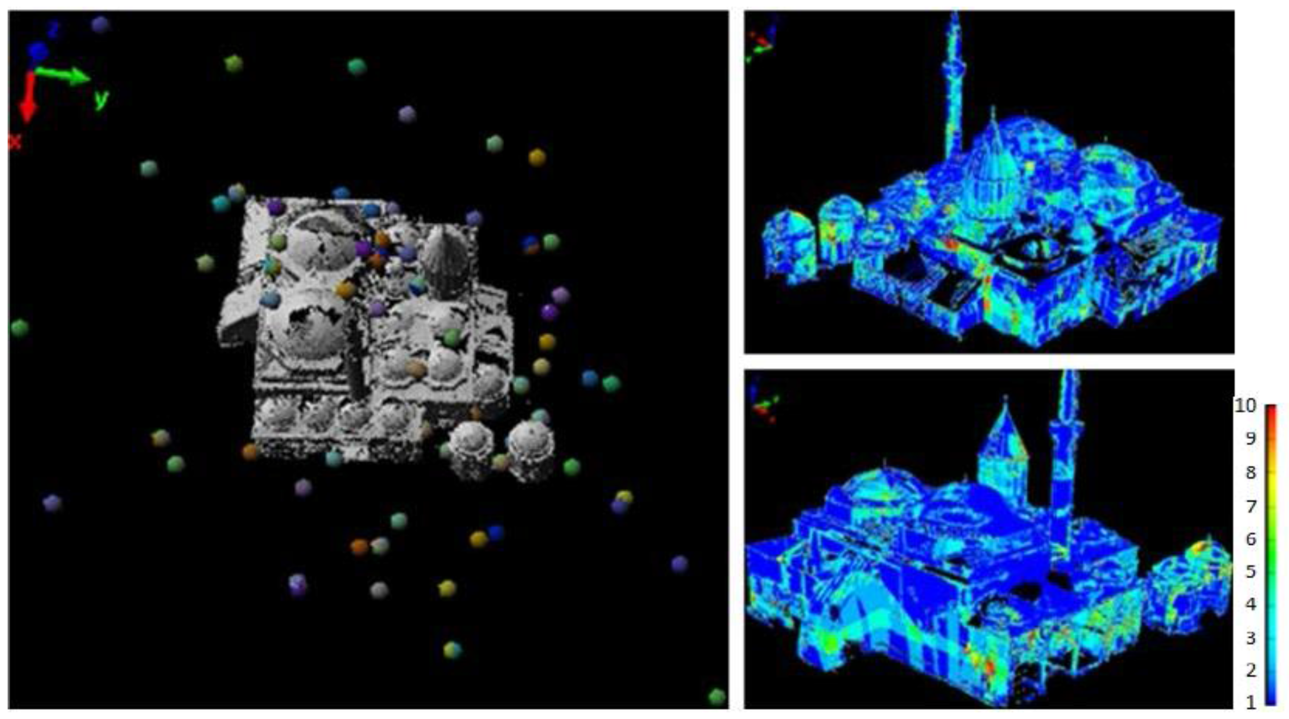
6. Georeferencing and 3D Model Accuracy Evaluation
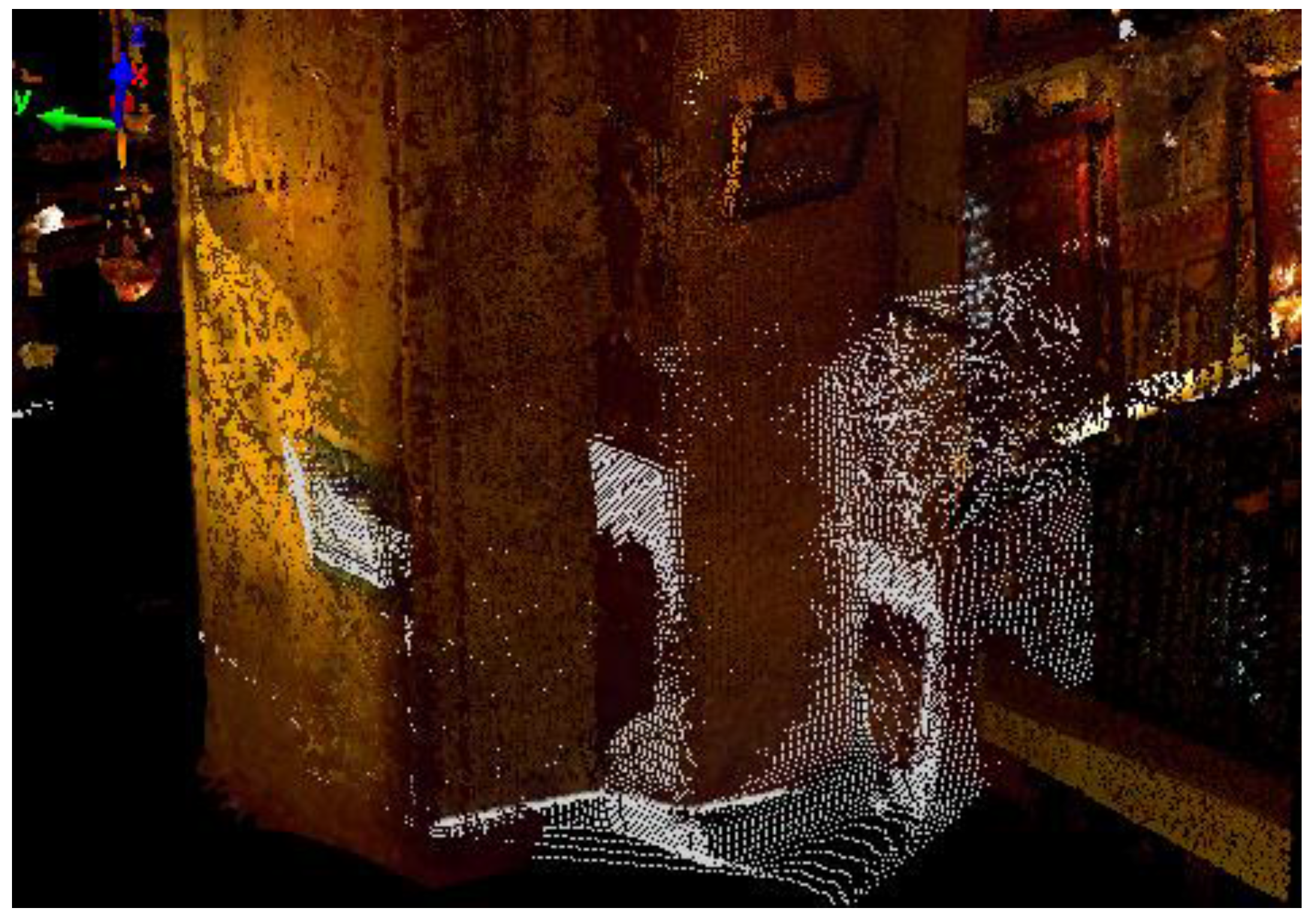
We grouped together the final georeferencing of any point clouds in a common reference frame and the assessment of 3-D model accuracy because both were based on the measurement of an independent set of control points (CP). These consisted of thirty-six control points that could be well distinguished in the TLS/ToF point clouds (Figure 11). A local geodetic 3-D network was set up to measure CP coordinates. A Topcon GPT-3007N theodolite was employed for this purpose, which allowed for measuring CP 3-D coordinates thanks to the integrated reflectorless rangefinder. Considering the intrinsic measurement precision of such an instrument, the error related to the determination of the network’s stations, and the use of reflectorless mode, the precision of CPs has been evaluated to be better than ±5 mm in all directions [54]. This precision is superior to the one of 3D points from TLS and ToF imaging.
The indoor and outdoor point clouds were georeferenced and aligned by using 3-D rigid-body transformations on the basis of CPs, whose coordinates were identified in the 3-D model. After georeferencing, the accuracy assessment was carried out by using a set of check points (ChP) made up of those CPs that had not been adopted for georeferencing. The metric used for evaluating the accuracy was the RMSE of 3-D residuals on ChPs (Table 1). The average residuals of the ChP coordinates were less than one centimeter and their standard deviations were about 2 cm. These are very good results when compared to the average point spacing (ranging between 1 cm and 3 cm) of laser scanning data. On the other hand, a rigorous quality assessment was carried out by the comparison of CPs distances between coordinates in the point cloud to the ones in the geodetic measurements. Globally, two subsets of 16 and 20 CPs were selected for quality assessment of indoor and outdoor point clouds, respectively. The average results showed high accuracy of 3-D modeling (Table 2 and Table 3). According to these results, the accuracy of the obtained 3-D point cloud model was positively evaluated.

7. Texture Mapping

Although the 3-D point cloud model represents the shape of the measured object, it does not have texture data to render a realistic visualization. When the texture data of the object is requested to be recorded in addition to the geometric data, a photorealistic texture has to be mapped on the point cloud after meshing to obtain a continuous surface connecting discrete points. Thus, both geometry and texture data can be visualized together. In order to map the texture, first the triangulated (mesh) model surface has to be derived from the raw point cloud [48]. The triangulated model depicts the model shape with triangles adjacent to each other through the object surface.
Texturing images over a mesh requires the knowledge of the camera interior orientation and exterior orientation of any stations [49]. The former can be obtained from the preliminary camera calibration. The latter may be computed by following one of the photogrammetric procedures for image orientation. In this case, the presence of several images, which are not well connected in a photogrammetric network, led us to prefer the space resection method for computing the exterior orientation in an independent way for any camera stations. This task, theoretically, required the computation of at least three corresponding control points (CP) visible in both the image and the mesh. Alternatively, ground control points (GCP) can be used. Due to some numerical problems (space resection models are non-linear), usually the computational methods require more points, a fact that may also increase the redundancy of the observations.
The triangulated surface was created in PolyWorks® software. Unlike in many software packages that implement the triangulation process is 2.5-D, in PolyWorks® a real 3-D data triangulation can be done. After creating the mesh model, editing was required to fix some residual problems. The triangulated image of the dome belonging to Semahane can be seen on Figure 12.
PI-3000 software (ver. 3.21) was used to map photo-texture on the triangulated model of the museum. The triangulated model from PolyWorks was transferred to PI-3000 software using the DXF format. The images captured by the Nikon D80 camera were also imported into the software. The photographs which will be used for texture mapping were selected interactively. They were registered to the object (point cloud) coordinate system with conjugated points chosen from the photograph and the point cloud. Then, 3-D virtual models and orthophoto images [55] were created by mapping photo-textures onto the triangulated model (Figure 13). Similarly, the triangulated and texture-mapped models of the Mihrabs in Huzur-ı Pir section and the door of the Masjid were created (Figure 14).

8. Conclusions

In this study, a 3-D model of the Mevlana Museum (Konya, Turkey) was created using TLS and ToF imaging datasets. While the application of TLS for 3-D modeling of cultural heritage has been largely proved to be effective in projects carried out so far, here, the usability of a ToF camera in documentation studies of historical structures was investigated. The areas that cannot be measured with laser scanning were measured by a ToF camera and a final unique point cloud model was generated by merging both datasets. In fact, ToF cameras can be handled with ease due to the light weight and the capability of recording images when in motion. However, the short measurement range of the ToF cameras can be seen as a drawback of this technology, even though this limitation is going to be overcome in future sensors. In addition, since the point cloud of ToF camera does not have any color, it is difficult to select details. These deficiencies limit the use of a ToF camera in full 3-D modeling studies.
The object spatial sampling resolution at the maximum measurement distance from the camera is approximately 2 cm. The point clouds recorded by the ToF cameras can be combined using ICP registration. Moreover, integration of point clouds from the ToF camera and laser scanner can be also accomplished using ICP.
The terrestrial laser scanning method, which has been used for modeling historical structures for nearly twenty years, has been proved to be an efficient measurement technique in the field of cultural heritage documentation. The laser scanning of indoor and outdoor surfaces were performed in six days. The measurement of the roof and indoor complex details was especially time consuming. On the other hand, large scale data is a burden on computer capacity. The computer that was used to process the data had an Intel Core i5-2400 CPU processor and 8 GB RAM. The process required about five days for completion. At the end of this project, all the details of the Mevlana Museum were measured and the 3-D virtual model was created. The quality assessment showed that the point cloud models were created with high accuracy despite of the large number of measurements and the complex structure of the building. On the other hand, georeferencing of the measurements was made by using adequate numbers of control points with high accuracy. In addition, texture mapping with digital images recorded by an independent SLR camera allowed an increase in the information content of the final 3-D model.

Acknowledgments

This study was funded by The Scientific and Technological Research Council of Turkey (TUBITAK) with project number 112Y025.

Author Contributions

Cihan Altuntas was the primary author of this article. Each of the co-authors Ferruh Yildiz and Marco Scaioni contributed to the article on a roughly equally basis. All authors reviewed the final version of the article.

Conflicts of Interest

The authors declare no conflict of interest.

References

  1. Seker, D.Z.; Alkan, M.; Büyüksalih, G.; Kutoglu, S.H.; Kahya, Y.; Akcin, H. Kültürel Mirasın Kaydı, Analizi, Korunması ve Yaşatılmasına Yönelik Bir Bilgi ve Yönetim Sisteminin Geliştirilmesi, Örnek Uygulama: Safranbolu Tarihi Kenti; The Scientific and Technological Research Council of Turkey (TUBITAK): Ankara, Turkey, 2011. [Google Scholar]
  2. Gruen, A.; Remondino, F.; Zhang, L. Document photogrammetric reconstruction of the Great Buddha of Bamiyan, Afghanistan. Photogramm. Rec. 2004, 19, 177–199. [Google Scholar] [CrossRef]
  3. Remondino, F. Heritage recording and 3D modeling with photogrammetry and 3D scanning. Remote Sens. 2011, 3, 1104–1138. [Google Scholar] [CrossRef] [Green Version]
  4. Remondino, F.; Boehm, J. Editorial: Theme section, terrestrial 3D modeling. ISPRS J. Photogram. Remote Sens. 2013, 76, 31–32. [Google Scholar] [CrossRef]
  5. Murphy, M.; McGovern, E.; Pavia, S. Historic building information modelling—Adding intelligence to laser and image based surveys of European classical architecture. ISPRS J. Photogram. Remote Sens. 2013, 76, 89–102. [Google Scholar] [CrossRef]
  6. Oreni, D.; Brumana, R.; Torre, S.D.; Banfi, F.; Barazzetti, L.; Previtali, M. Survey turned into HBIM: The restoration and the work involved concerning the Basilica di Collemaggio after the earthquake (L’Aquila). In Proceedings of the ISPRS Technical Commission V Symposium, Riva del Garda, Italy, 23–25 June 2014; pp. 267–273.
  7. Scaioni, M.; Vassena, G.; Kludas, T.; Pfeil, J.U. Automatic DEM generation using digital system InduSCAN: An application to the artworks of Milano Cathedral finalized to realize physical marble copies. In Proceedings of the XVIIIth ISPRS Congress, Vienna, Austria, 9–19 July 1996; pp. 581–586.
  8. Kedzierski, M.; Fryskowska, A. Methods of laser scanning point clouds integration in precise 3D building modelling. Measurement 2015, 74, 221–232. [Google Scholar] [CrossRef]
  9. Blais, F.; Beraldin, J.A. Recent developments in 3D multi-model laser imaging applied to cultural heritage. Mach. Vis. Appl. 2006, 17, 395–409. [Google Scholar] [CrossRef]
  10. El-Hakim, S.; Gonzo, L.; Voltolini, F.; Girardi, S.; Rizzi, A.; Remondino, F.; Whiting, E. Detailed 3D modelling of castles. Int. J. Archit. Comput. 2007, 5, 200–220. [Google Scholar] [CrossRef]
  11. Barazzetti, L.; Binda, L.; Scaioni, M.; Taranto, P. Importance of the geometrical survey for structural analyses and design for intervention on C.H. buildings: Application to a My Son Temple in Vietnam. In Proceedings of the 13th International Conference on Repair, Conservation and Strengthening of Traditionally Erected Buildings and Historic Buildings, Wroclaw, Poland, 2–4 December 2009; pp. 135–146.
  12. Alsadik, B.; Gerke, M.; Vosselman, G. Automated camera network design for 3D modeling of cultural heritage objects. J. Cult. Hérit. 2013, 14, 515–526. [Google Scholar] [CrossRef]
  13. Grussenmeyer, P.; Hanke, K. Cultural heritage applications. In Airborne and Terrestrial Laser Scanning; Vosselman, G., Maas, H.-G., Eds.; Whittles Publishing: Caithness, UK, 2010; pp. 271–290. [Google Scholar]
  14. Akca, D.; Remondino, F.; Novàk, D.; Hanusch, T.; Schrotter, G.; Gruen, A. Recording and modeling of cultural heritage objects with coded structured light projection systems. In Proceedings of the 2nd International Conference on Remote Sensing in Archaeology, Rome, Italy, 4–7 December 2006; pp. 375–382.
  15. Grussenmeyer, P.; Alby, E.; Assali, P.; Poitevin, V.; Hullo, J.F.; Smiciel, E. Accurate documentation in cultural heritage by merging TLS and high-resolution photogrammetric data. Proc. SPIE 2011. [Google Scholar] [CrossRef]
  16. Alba, M.; Scaioni, M. Comparison of techniques for terrestrial laser scanning data georeferencing applied to 3-D modelling of cultural heritage. In Proceedings of the 3D-ARCH, Zurich, Switzerland, 12–13 July 2007; pp. 1–8.
  17. Salvi, J.; Matabosch, C.; Fofi, D.; Forest, J. A review of recent range image registration methods with accuracy evaluation. Image Vis. Comput. 2007, 25, 578–596. [Google Scholar] [CrossRef]
  18. Aquilera, D.G.; Gonzalvez, P.R.; Lahoz, J.G. An automatic procedure for co-registration of terrestrial laser scanners and digital cameras. ISPRS J. Photogramm. Remote Sens. 2009, 64, 308–316. [Google Scholar]
  19. Altuntas, C. Pair-wise automatic registration of three-dimensional laser scanning data from historical building by created two-dimensional images. Opt. Eng. 2014, 53, 1–6. [Google Scholar] [CrossRef]
  20. Haala, N. The landscape of dense image matching algorithms. In Proceedings of the Photogrammetric Week 2013, Stuttgart, Germany, 9–13 September 2013; pp. 271–284.
  21. Barazzetti, L.; Scaioni, M.; Remondino, F. Orientation and 3D modelling from markerless terrestrial images: Combining accuracy with automation. Photogramm. Rec. 2010, 25, 356–381. [Google Scholar] [CrossRef]
  22. Remondino, F.; Spera, M.G.; Nocerino, E.; Menna, F.; Nex, F. State of the art in high density image matching. Photogramm. Rec. 2014, 29, 144–166. [Google Scholar] [CrossRef]
  23. Colomina, I.; Molina, P. Unmanned aerial systems for photogrammetry and remote sensing: A review. ISPRS J. Photogramm. Remote Sens. 2014, 92, 79–97. [Google Scholar] [CrossRef]
  24. Remondino, F.; Stoppa, D. ToF Range-Imaging Cameras; Springer: Berlin, Germany, 2013. [Google Scholar]
  25. Rinaudo, F.; Chiabrando, F.; Nex, F.; Piatti, D. New instruments and technologies for cultural heritage survey: Full integration between point clouds and digital photogrammetry. In Digital Heritage; Ioannides, M., Ed.; Springer: Berlin, Germany, 2010; pp. 56–70. [Google Scholar]
  26. Chiabro, F.; Rinaudo, F. ToF cameras for architectural surveys. In TOF Range-Imaging Cameras; Remondino, F., Stoppa, D., Eds.; Springer: Berlin, Germany, 2013; pp. 139–164. [Google Scholar]
  27. Rinaudo, F.; Chiabrando, F. Calibrating and evaluating a range camera for cultural heritage metric survey. In Proceedings of the XXIV International CIPA Symposium, Strasbourg, France, 2–6 September 2013; pp. 271–276.
  28. Republic of Turkey Ministry of Culture and Tourism. Available online: http://www.kulturvarliklari.gov.tr/TR,43870/konya---mevlana-muzesi.html (accessed on 3 December 2012).
  29. GEO3D Optech Ilris-3D Specifications. Available online: http://www.geo3d.hr/download/ilris_3d/brochures/ilris_36d.pdf (accessed on 10 January 2013).
  30. Vosselman, G.; Maas, H.G. Airborn and Terrestrial Laser Scanning; Whittles Publishing: Caithness, UK, 2010. [Google Scholar]
  31. Clark, J.; Robson, S. Accuracy of measurements made with a Cyrax 2500 laser scanner. Surv. Rev. 2004, 37, 626–638. [Google Scholar] [CrossRef]
  32. Vezočnik, R.; Ambrožič, T.; Sterle, O.; Bilban, G.; Pfeifer, N.; Stopar, B. Use of terrestrial laser scanning technology for long term high precision deformation monitoring. Sensors 2009, 9, 9873–9895. [Google Scholar] [CrossRef] [PubMed]
  33. Gikas, V. 3D terrestrial laser scanning for geometry documentation and construction management of highway tunnels during excavation. Sensors 2012, 12, 11249–11270. [Google Scholar]
  34. Hussmann, S.; Ringbeck, T.; Hagebeuker, B. A Performance review of 3D ToF vision systems in comparison to stereo vision systems. In Stereo Vision; Bhatti, A., Ed.; InTech: Rijeka, Croatia, 2008; pp. 103–120. [Google Scholar]
  35. Piatti, D.; Rinaudo, F. SR-4000 and CamCube 3.0 Time of Flight (ToF) cameras: Tests and comparison. Remote Sens. 2012, 4, 1069–1089. [Google Scholar]
  36. MesaImaging, SwissRanger SRSR4000 Overview. Available online: http://www.mesa-imaging.ch/products/sr4000/ (accessed on 9 March 2015).
  37. Piatti, D. Time-of-Flight Cameras: Tests, Calibration and Multi Frame Registration for Automatic 3D Object Reconstruction. Ph.D. Thesis, Politecnico di Torino, Torino, Italy, 2010. [Google Scholar]
  38. Lichti, D.D.; Qi, X.; Ahmed, T. Range camera self-calibration with scattering compensation. ISPRS J. Photogramm. Remote Sens. 2012, 74, 101–109. [Google Scholar] [CrossRef]
  39. Valverdea, S.A.; Castilloa, J.C.; Caballeroa, A.F. Mobile robot map building from time-of-fight camera. Expert Syst. Appl. 2012, 39, 8835–8843. [Google Scholar] [CrossRef]
  40. Oggier, T.; Büttgen, B.; Lustenberger, F.; Becker, G.; Rüegg, B.; Hodac, A. SwissRanger SR3000 and first experiences based on miniaturized 3D-ToF cameras. In Proceedings of the 1st Range Imaging Research Day, Zurich, Switzerland, 8–9 September 2005; pp. 97–108.
  41. Boehm, J.; Pattinson, T. Accuracy of exterior orientation for a range camera. In Proceedings of the ISPRS Commission V Mid-Term Symposium, Newcastle upon Tyne, UK, 21–24 June 2010; pp. 103–108.
  42. Cui, Y.; Schuan, S.; Chan, D.; Thrun, S.; Theobalt, C. 3D shape scanning with a time-of-flight camera. In Proceedings of the IEEE Conference on Computer Vision and Pattern Recognition (CVPR), San Francisco, CA, USA, 13–18 June 2010; pp. 1173–1180.
  43. Altuntas, C.; Yildiz, F. The registration of point cloud data from range imaging camera. Géod. Cartogr. 2013, 39, 106–112. [Google Scholar] [CrossRef]
  44. Lichti, D.D.; Jamtsho, S.; El-Halawany, S.I.; Lahamy, H.; Chow, J.; Chan, T.O.; El-Badry, M. Structural deflection measurement with a range camera. ASCE J. Surv. Eng. 2012, 138, 66–76. [Google Scholar] [CrossRef]
  45. Qi, X.; Lichti, D.D.; El-Badry, M.; Chan, T.O.; El-Halawany, S.I.; Lahamy, H.; Steward, J. Structural dynamic deflection measurement with range cameras. Photogramm. Rec. 2014, 29, 89–107. [Google Scholar] [CrossRef]
  46. Ganapathi, V.; Plagemann, C.; Koller, D.; Thrun, S. Real time motion capture using a single time-of-flight camera. In Proceedings of the IEEE Conference on Computer Vision and Pattern Recognition (CVPR), San Francisco, CA, USA, 13–18 June 2010; pp. 755–762.
  47. Clemente, L.A.; Davison, A.J.; Reid, I.D.; Neira, J.; Tardos, J.D. Mapping large loops with a single hand-held camera. In Proceedings of the Robotics: Science and Systems, Atlanta, GA, USA, 27–30 June 2007.
  48. Previtali, M.; Barazzetti, L.; Scaioni, M. An automated and accurate procedure for texture mapping from images. In Proceedings of the 18th International Conference on Virtual Systems and Multimedia (VSMM), Milan, Italy, 2–5 September 2012; pp. 591–594.
  49. Luhmann, T.; Robson, S.; Kyle, S.; Böhm, J. Close Range Photogrammetry: 3D Imaging Techniques; Walter De Gruyter: Berlin, Germany, 2013; p. 702. [Google Scholar]
  50. Yu, Y.; Debevec, P.; Malik, J.; Hawkins, T. Inverse global illumination: Recovering reflectance models of real scenes from photographs. In Proceedings of the 26th Annual Conference on Computer Graphics and Interactive Techniques, Los Angeles, CA, USA, 8–13 August 1999; pp. 215–227.
  51. Yang, H.; Welch, G.; Pollefeys, M. Illumination intensive model-based 3D object tracking and texture refinement. In Proceedings of the 3rd International Symposium on 3D Data Processing, Visualization, and Transmission (3DPVT’06), Chapel Hill, NC, USA, 14–16 June 2006; pp. 869–876.
  52. PolyWorks Software, version 9.0, InnovMetric Software Inc.: Ville de Québec, QC, Canada, 2007.
  53. Pomerleau, F.; Colas, F.; Siegwart, R.; Magnenat, S. Comparing ICP variants on real-world data sets. Auton. Robot. 2013, 34, 133–148. [Google Scholar] [CrossRef]
  54. Schofield, W.; Breach, M. Engineering Surveying, 6th ed.; Butterworth-Heinemann: Oxford, UK, 2007. [Google Scholar]
  55. Yastikli, N. Documentation of cultural heritage using digital photogrammetry and laser scanning. J. Cult. Hérit. 2007, 8, 423–427. [Google Scholar] [CrossRef]
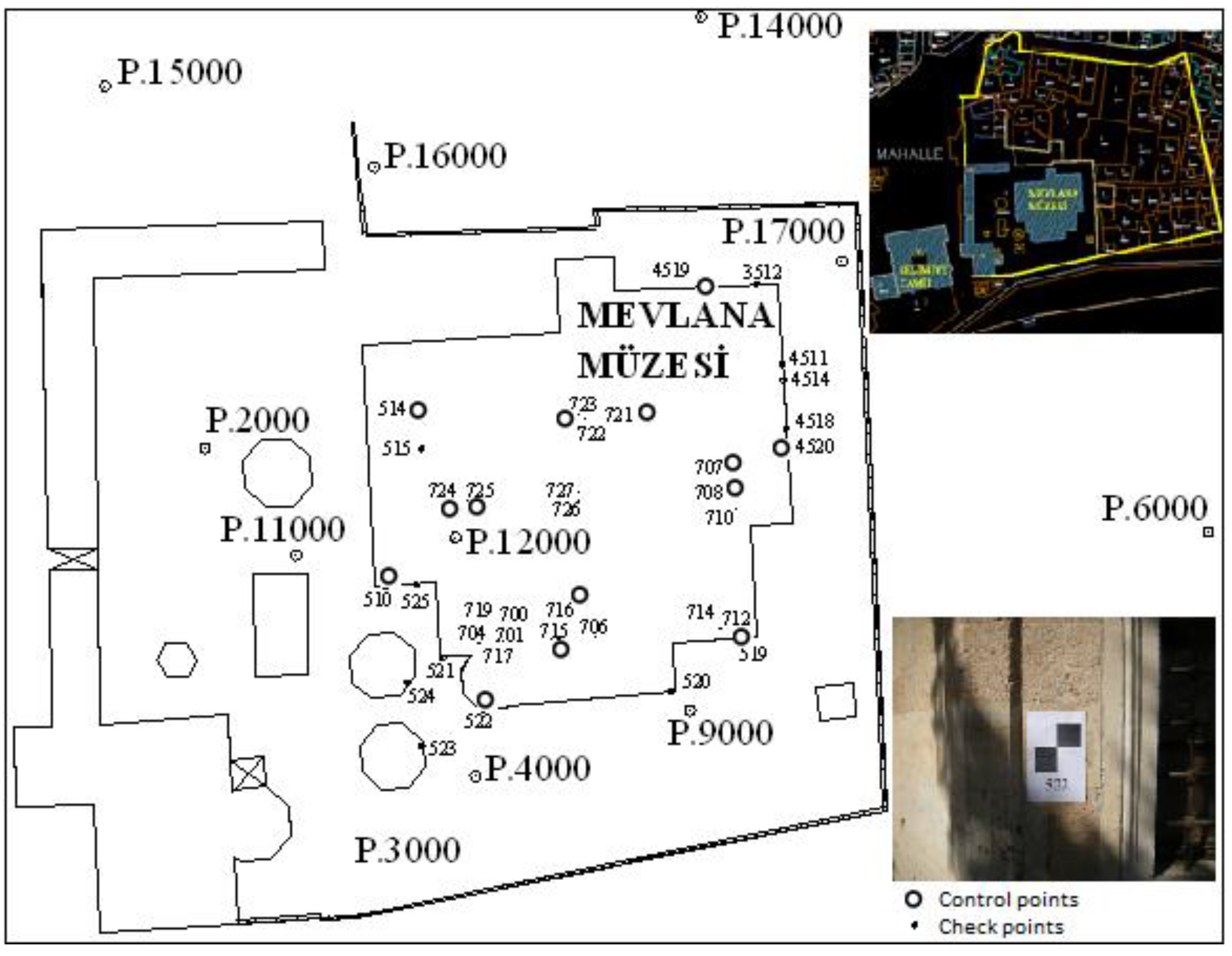
Figure 1. Mevlana Museum.
Ijgi 05 00018 g001
Figure 2. Ground plan of Mevlana Museum.
Ijgi 05 00018 g002
Figure 3. The flowchart of the surveying and 3-D modeling methodology.
Ijgi 05 00018 g003
Figure 4. Coordinate axis of the SwissRanger SR4000 camera.
Ijgi 05 00018 g004
Figure 5. The outside of the museum was measured by laser scanner from 110 stations. Some details were scanned many times with overlapped measurements. The color legend on the right shows the repeated measurements (for example, red areas were measured10 times).
Ijgi 05 00018 g005
Figure 6. The outside 3-D point cloud model of the Mevlana Museum. The images are from west (left) and north (right) sides.
Ijgi 05 00018 g006
Figure 7. The inside 3-D point cloud model with color.
Ijgi 05 00018 g007
Figure 8. The Mihrab in Huzur-ı Pir section was measured with a SR4000 camera from two stations. Intensity images (top), and point clouds (below).
Ijgi 05 00018 g008
Figure 9. The Mihrab in Masjid was measured from three stations with a SR4000 camera. The registration of the measurements relation to the first point cloud was applied by ICP. Intensity images (top), and combined point clouds (below).
Ijgi 05 00018 g009
Figure 10. The point clouds of the ToF camera and TLS were combined with ICP.
Ijgi 05 00018 g010
Figure 11. Control points were measured from traverse points. Georeferencing of the inside and outside point cloud models were executed by ground control points. The accuracy of the georeferencing was assessed by check points.
Ijgi 05 00018 g011
Figure 12. The point cloud (top-left), solid (top-right), and mesh (below) visualization of Semahane’s dome.
Ijgi 05 00018 g012
Figure 13. Orthophoto and texture mapped 3-D model of the dome of Semahane.
Ijgi 05 00018 g013
Figure 14. Texture mapped 3-D models of Mihrabs in Huzur-ı Pir section (left, middle) and the door of Masjid (right).
Ijgi 05 00018 g014
Table 1. The georeferencing results of inside and outside point cloud model of the Mevlana Museum.
Point CloudControl Points #Check Points #Average Residuals (m)Std.Dev.of Residuals (m)
dxdydzσxσyσz
Outside6100.005−0.002−0.0040.0220.0130.007
Inside9110.014−0.0040.0070.0200.0260.026
Table 2. The quality assessment criteria (df) for the outside 3-D point cloud model of the Mevlana Museum.
Control/Check Point LineITRF-2005 Distance (m)TLS Distance (m)Discrepancy (m)df (m)
522–52513.71613.705−0.0110.023
525–5103.0663.052−0.014
510–5218.8808.9020.021
521–5244.2074.2180.011
524–5236.3146.278−0.035
523–52024.65824.654−0.004
520–5199.1579.1670.010
519–51438.74438.714−0.030
514–5153.5663.541−0.024
515–451934.23734.2550.018
4519–35122.5352.5650.030
3512–45149.6619.647−0.014
4514–45111.6111.573−0.038
4511–45208.2938.3320.038
4520–45181.9741.965−0.008
Table 3. The quality assessment criteria (df) for the inside 3-D point cloud model of the Mevlana Museum.
Control/Check Point LineITRF-2005 Distance (m)TLS Distance (m)Discrepancy (m)df (m)
707–7081.2771.295−0.0180.024
708–72215.95115.982−0.030
722–7231.1611.1480.013
723–7213.0893.0540.035
721–71521.40821.425−0.017
715–7162.4402.445−0.004
716–72417.08717.0600.027
724–7251.2521.2220.030
725–70618.09818.106−0.008
706–72613.44013.4110.029
726–7270.6800.694−0.015
727–71015.20015.1690.031
710–70025.91225.9120.001
700–7011.2961.316−0.020
701–7042.3282.365−0.037
704–7175.1365.1170.019
717–7193.2173.249−0.032
719–71223.74423.754−0.010
712–7142.5592.594−0.035

