1. Introduction
Photorealistic visualization is not only one of the key technologies of Geographic Information Systems (GIS), but also one of the basic elements for public geospatial services [
1]. As one of the basic functions in GIS, the ability to visualize 3D spatial information in an efficient, photorealistic, and real-time manner has become an important indicator for the performance of systems [
2]. The advancement of modeling technologies and the improvement of the measurement of accuracy have made the understanding and usage of geographic information transition from the traditional vector or raster of the 2D age into a new 3D age in which objects can be represented by an accurate geometry model with high quality textures and a spatial-temporal mode with dynamic features. The volume of geospatial data has experienced exponential growth, and the data that need to be rendered are far beyond the processing abilities of current personal computers (PCs) [
3]. Making full use of the existing multi-CPU (Central Processing Unit) and multi-GPU (Graphics Processing Unit) architectural features to speed up the data processing and visualization of large-scale geospatial data has become a hot research issue, as well as a large challenge in the fields of geographic information science and computer graphics science.
Real-time visualization is generally described as a cyclical procedure that can be divided into three stages: the application stage, the geometry processing stage, and the fragment processing stage [
4]. Since the 1990s, the analysis and realization of parallel processing for real-time visualization have fallen into two categories. The first type is process based, which appeared in the earlier years of the PC age, when the processing abilities of the CPUs were not powerful enough. The procedure of the visualization stage can be divided into four tasks: the visibility calculation task, the render task, the data loading task, and the LOD (Level of Detail) selection task. Each task is handled in a separate CPU and is run as a process. This kind of processing method has wide applications. The UC Berkeley walkthrough system [
5] takes four CPUs to perform the tasks. Each CPU of the system runs one process, and each process of the CPU performs one task. The Massive Model Rendering (MMR) system [
6] decomposes the procedure of visualization into eight tasks, namely culling, LOD selection, view frustum culling, occlusion culling, occlusion rendering, Textured Depth-Mesh (TMD) rendering, geometry rendering, and pre-fetch asynchronously. These tasks are performed in four CPUs. Each CPU runs two processes, and each process binds with one task. The second type of parallel processing is thread based, which appears in the fast developing times of the CPU with a hyper-thread and multi-core trend. This kind of processing method adopts the same strategy as the previous method. Both of them break down the procedure of visualization into several tasks. However, the thread-based method performs each task in a single thread. The iWalk system [
7] breaks down the procedure of visualization into five tasks, which are approximate calculation for visibility, conservation calculation for visibility, rendering, look-ahead pre-fetching, and loading form disks, and each task is attached to one independent thread. The Quick-VDR system [
8] divides the rendering process into four tasks, namely LOD selection, occlusion culling, rendering, and data fetching. The feature of this system that is different from others is that each task may be performed in more than one thread. For example, the data fetching task runs in two threads to load the data from external memory. The Geomorphing of Levels of Detail (GoLD) system [
9] breaks down the procedure of visualization into five tasks, including LOD selection, occlusion culling, rendering, geometry data loading, and texture data loading. The system takes only two threads to perform the above five tasks, one thread for the data loading task and the other thread for all other tasks. The ANYGL system [
10] adopts a different strategy in which the six tasks, namely visibility calculation, LOD selection, rendering, disk mapping for data loading, data pre-fetch asynchronously, and disk mapping replacement, are cataloged into three types and each type can be performed by multiple threads.
In the field of Geographic Information Science, many studies have been conducted to investigate the high efficient rendering in 3DGIS (three-dimensional Geographic Information Systems). Zheng [
11] proposed a parallel dynamic storage and rendering algorithm based on integer wavelet transform and restricted quad-tree combination in a GPU to reduce the impacts of data updating and data storage to real-time terrain deformation for a dynamic rendering speed. The high-precision surface modelling method, which is GPU accelerated, can also be used to create a high accuracy Digital Elevation Model (DEM) [
12]. According to different characteristics of parallel algorithms, Song [
13] noted that the data divide mechanism has become the key issue among research problems. Other kinds of methods, such as Map Reduce [
14], divide the grid area into raster cells and assign every raster data to different calculating units to achieve parallel computing for terrain processing. To achieve efficient rendering of 3D models, Xu [
15] proposed a fast data loading strategy, which combined the data-bind stream reader through a multi-thread parallel processing algorithm, and implied a new data re-organized method by converting the CityGML city model into a grid Direct3D object. To process the remote sensing images efficiently, a CPU and GPU co-processing mode is performed through orthorectify. Xie [
16] took full advantages of the natural features of the parallel patterns in remote sensing images, and Guo [
17] explored the usage of GPU for image matching. Aiming at the specific tasks, the optimization algorithms are implied by using a CPU and GPU collaborative model for parallel processing. The traditional methods of visualization in 3DGIS mainly focus on the issues of symbolization, scale, and representation in three dimensions. In the era of big data, given the massive volume, dynamic changes, and uncertainty of data, it is urgent to develop new interactive and dynamic demonstration methods to explore the discoveries and to develop a visual analytics method combined with geographic calculations, including statistics or data mining. These methods have become important characteristics of GIS big data [
18].
In summary, there is no a systematic analysis for real-time visualization of urban 3DGIS in the fields of computer graphics or geographic information science. Real-time visualization for the dynamic observation targets and the sensor data has become an urgent topic, especially since Real-Time GIS has been proposed [
19]. We need to investigate a method for real-time big data processing from a theoretical model to a real tool.
This paper first summarizes the basic procedure of real-time visualization of urban 3DGIS and then analyzes the pipelines of the real-time rendering process of the visualization. Furthermore, the decomposition of the pipeline with tasks is taken by the task order in the pipeline and the data input-output dependency between adjacent tasks. After that, the data characteristics of the basic algorithms inside tasks are evaluated. On this basis, this paper proposes a parallel co-processing mode and a collaborative strategy for real-time visualization of urban 3DGIS. This method seems to provide effective evidence for the development of rendering applications of 3DGIS systems.
2. Procedure Analysis on Real-time Visualization of Urban 3DGIS
As one of the visualization methods of 3D city models, the vector-based visualization method uses a vector to represent 3D models. After the view point and the view directions are set, considerable processing such as shading, occlusion, lighting, texture mapping, projection, and finally a photograph are generated to reflect the virtual scene [
20]. The tasks and functions associated with the visualization of 3D city models can be summarized as multi-view browsing, zooming in and out, walking-through, rotating, and flying by any router and driver on ground [
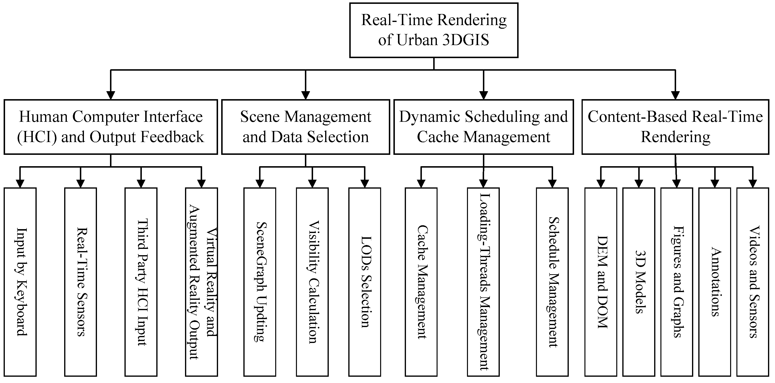
21]. With the development of real-time GIS, the requirement for visualization ability has grown rapidly, which can process various data acquired from space, airplane, and ground equipment sensors or generated by new interface techniques, such as somatosensory interactive devices, or virtual reality and augmented reality sensor devices. The real-time visualization of urban 3DGIS should be able to process the exponentially growing data with limited memory, manage the scene graph, and schedule the large-scale data dynamically and effectively. The procedures range from the data input, scene management, and dynamic scheduling to real-time rendering. The basic procedure of visualization of urban 3DGIS is shown in
Figure 1.
Similar to the methods in computer science, the visualization procedure mentioned in this paper takes the real-time visualization of urban 3DGIS as a pipeline and then divides the pipeline into four stages based on the task order and the data input-output dependency. They are the human interface and output feedback stage, scene management and data selection stage, scheduling and cache management stage, and the content-based real-time rendering stage. Each stage can be further divided into several tasks. In the stage of human-interface and output feedback, the urban 3DGIS system can process the input data from commonly used devices such as a mouse and keyboard. In addition, with the fast development of virtual reality and augmented reality, the system should have the ability to address all kinds of signals acquired from real-time input sensors, attached systems, and holographic interactive input devices and virtual glasses, such as Kinect, Google Glass+, Oculus, and HoloLens. The input signals will be converted into commands as soon as they are transferred into the system, and then these commands will be calculated into parameters used for visualization. In the stage of scene management and data selection, the nodes of the scene graph are first updated with the data change, and then the visible nodes are calculated according to the visual conditions. At the end of the stage, a node list is generated for data loading, and a list of objects is also generated for rendering. One more important job in this stage is that the suitable LODs of the data should be selected based on the balance between the rendering quality and the cost of rendering. In the stage of scheduling and cache management, a high-efficient buffer management method is implemented for a limited memory size. It allocates threads to load the data dynamically and unload the unnecessary data to maintain a suitable size. In the stage of content-based real-time rendering, the data are pushed into the cache for rendering. The data contents include DEM, DOM, 3D models, vector-based data, figures, notations, annotations, and stream-based real-time input data. The sub-tasks in this stage include the data division of content, the setup of elementary graphics, the creation of the texture objects, the data transformation into GPU, and the geometry and pixel processing to generate the output image.
3. Real-Time Visualization Pipeline of Urban 3DGIS
The visualization of urban 3DGIS is a process that maps the digital value into a cognitive scale and transfers the information in a visual manner, and it is also a calculation process from the description of a scene to image generation [
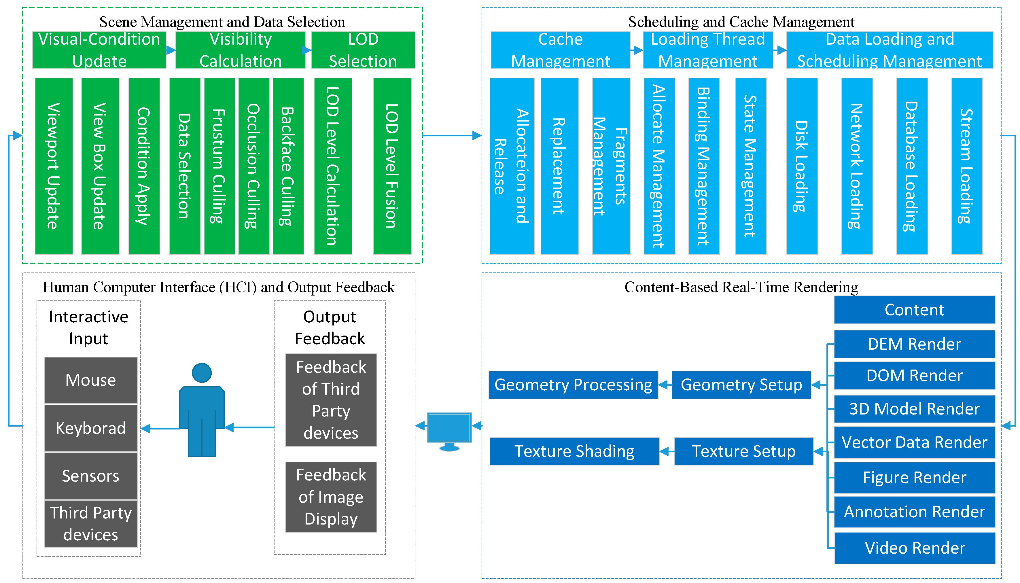
22]. In this paper, we describe the detail process of rendering pipeline of urban 3DGIS, as shown in
Figure 2. First, the system catches the signals from the input devices such as a mouse, a keyboard, sensors, and other third-party devices. The signals might be a moving view point, a query box, a gesture, and/or a voice command. Then, all of these signals are converted into a visual box, which is the most important parameter used to calculate the visual objects and suitable LODs. Based on the calculated visual object list and the LODs, the data content of the object lists that are located in external memory are loaded into the main memory by multi-threads. After, the loaded data are processed by Graphic Application Programming Interfaces (APIs), such as OpenGL or DirectX, by the steps of rendering environment setting, primitive setup, and state setting. Finally, the data primitives, the draw commands, and control commands of the rendering are transferred into the graphic cache, such as frame buffer, and finally a picture is generated. After the user observes the image and then receives feedback, the visual condition changes and the process begins with the first step, which runs as loops. In such a manner, the procedure of real-time visualization of urban 3DGIS works on the pattern of a pipeline. The asynchronous pipelined manner can address the fluctuation of the frame rate caused by waiting and delay during the steps of synchronous serials and realize real-time and smooth visualization.
3.1. Pipeline Task Characteristics
The real-time rendering pipeline in computer graphics can be divided into the application stage, the geometric process stage, and the pixel process stage [
23,
24]. This method focuses on the tasks processed in the graphics hardware. In this paper, the pipeline for urban 3DGIS is divided into the human-computer interaction and output feedback stage, the scene management and data selection stage, the scheduling and cache management stage, and the content-based real-time rendering stage. The first three parts correspond to the application stage defined in computer graphics. The fourth part of the content-based real-time rendering stage can be subdivided into geometry processing and texture processing stages.
The task of the human-computer interaction and output feedback stage is to monitor all kinds of input devices and receive the input instruction and data stream. The input contents include mouse input signals, keyboard input signals, sensor data, and other input signals from third-party devices. The output to the following stage in the pipeline can be regarded as a visual output and feedback output, which are the images and the standard signals of the sensor devices.
The scene management and data selection stage can be subdivided into three tasks: the update services for visual conditions, the visibility calculation, and the LOD selection. The update services for visual conditions can be defined as when the system receives the input parameters, it converts them into a viewpoint position, and transfers them into a view volume box. The tasks of visibility calculation include traversing the scene graph and calculating the intersection of each node with the view volume box by performing the frustum visibility algorithm, occlusion culling calculation, and back visibility calculation. The list of visible scene nodes is the output for the next stage. The LOD selection entails calculating the distance between each node and the viewpoint by using the list of visible scene nodes. According to the projection screen error tolerance of projection screen and the distance, the appropriate LOD level for each node can be determined based on the storage of the data content of the node. Therefore, the input of this stage is the viewpoint parameter of the human-computer interaction, and the output for the next stage is an object list with its suitable LOD.
The scheduling and cache management stage can be subdivided into three tasks: cache management, multi-thread management, and dynamic scheduling management for data loading and unloading. Cache management needs to implement the allocation and deallocation algorithms for blocks of memory and a replacement policy to ensure high efficiency without duplication of loading from slow external storage devices. Multi-thread management develops a thread pool to manage bundles of threads. For the data that should be loaded, the threads are applied from the pool and then bound to certain loading jobs. The state of the thread will be monitored during the job, and then the thread will be returned to the pool when the job is finished. Data loading and unloading management makes it clear where the data are stored. The storage location will decide the method used for data loading by local disk data file reading, by network data transferring, by databases data loading, or by streaming. The output of this stage is a list of scene graph nodes with a data list.
The content-based real-time rendering stage decomposes the content of the data. The existing data type can be classified as DEM, DOM, 3D model, 2D vector, chart properties, annotation tags, and video data. All the data are analyzed and then expressed as a geometry with its corresponding texture units or data stream. After, all of the data will be set up by using the drawing APIs (such as OpenGL or DirectX) for the primitives and the texture units. The graphic APIs will try to package all the drawing commands and elements to create the display lists or high speed drawing orders, which will be sent to the graphics engine. Lastly, a resulting image is generated as the output to the frame buffer and is output by the display devices. The input data of this stage are the object list and the data list with its content, and the output are the displayed image and other feedbacks.
3.2. Data Characteristics in Task
The parallel patterns of real-time visualization of urban 3DGIS show the characteristics of the tasks’ parallel pattern in the pipeline and the data parallel pattern of algorithms in tasks. Thus, it is necessary to explore the characteristics of the data in each task of the stages in the pipeline. Based on the clear description about the data input-output dependency relationship between tasks, we can build the single instruction multiple data parallelism mode (SIMD mode) to improve the ability of real-time rendering of urban 3DGIS.
3.2.1. Human-Computer Interaction and Output Feedback Stage
The input data of this stage can be expressed as the instructions during the real-time rendering of 3DGIS and the feedback from the input sensors during the visualization process in each frame image. After the user observes the rendering image and decides the new feedback through the input devices or sensors, the new instructions will be generated and then converted to new parameters, which are the input data for the next stage.
3.2.2. Scene Management and Data selection Stage
The instructions of sensors in the previous stage can be converted into visual information. Further, the codes of sensors and visual information are calculated as the view point position or other parameters. In addition, the scene graph of the study area can be used as input data, and the visual conditions of the view point can be transferred into the view scope, which is represented as a view box. Then, the task of visibility calculation uses the scene bounding box as the parameter to perform frustum culling, back-face culling, and occlusion culling calculation. The data characteristics of these algorithms can be represented as faces of the view frustum, the bounding box of the nodes, objects and polygons of the objects, which are organized by the b-rep representation method. In LOD selection, the viewpoint and the positions of the nodes of the scene graph are used to compute the distance or projection error parameter, which are used to select the discrete LOD or to compute the continuous LOD for the connected scene graph nodes. The output of this stage is the visible list of nodes and the LOD parameters of the scene graph nodes.
3.2.3. Scheduling and Cache Management Stage
After the visibility calculation and data selection, the list of visible scene graph nodes and the LODs of each node are the input parameters for this stage. The dependent input data of this stage also include the geometry and texture data located in slow external memory and the sensor data from a data center or network. The organization structure of the data in external memory should be consistent with the data organization of the scene graph, which means that one can locate the external memory data storage of the object through the scene graph nodes. The data storage and organization in external memory are always established during the off-line process. The functions of the buffer management make the memory allocation and management in data blocks. The data characteristics represented in memory allocation are a data block. Data management and loading scheduling achieve the smooth loading of data from the external memory to the cache memory by multiple threads, and the data pattern is the block of the geometric data, the texture data, and the data stream of sensors.
3.2.4. Content-Based Real-Time Rendering Stage
This stage relies on the lists of data loading in caches, including the geometric data, texture data, and stream data of sensors. Taking the common implementation method into account, the cached data refer only to the data that have been loaded into the frame cache. They can also be called the cache rendering data of the current frame. The geometry processing task first breaks down the block data of the object into vertex and polygon data and then applies the model view transform, lighting calculations, projection computing, and cutting operations. For the texture data, the texture coordinate values are interpolated based on the vertex and original texture coordinate. Finally, the coordinates should be further transformed into the texture space, which can map the coordinate to draw an image to complete the geometry processing task. The input data of the pixel processing task include the vertex object and the texture object. The vertex object is the colored value generated in the vertex processing stage, and the texture object is produced through a command processing and texture format setup by the graphical interface API, such as OpenGL. Both of the above objects can be used to generate the fragment after the raster stage, and the fragment can be called as a pixel after the related operations. The final output of this stage is a generated image put to the frame buffer for display.
4. Parallel Mode of Tasks and Collaborative Mode of Data in Real-Time Visualization Pipeline
The frame rate required for real-time visualization is up to 15 frames per second (FPS) or more, whereas a frame rate of over 60 FPS is beyond the perceived sensitive ability of the human eye [
4]. Therefore, the time for each frame to be rendered is approximately 0.0167 to 0.067 seconds. Because the tremendous fluctuation frame rates will affect the user experience dramatically, it is a basic requirement for most real-time visualization applications to obtain a stable frame rate, such as a constant frame rate for films at 24 FPS or 30 FPS. In this paper, the real-time visualization pipeline of urban 3DGIS has been analyzed. However, the different visual conditions between frames can cause a large imbalance in data, which will result in a misbalance of the processor working load and create a stop or delay during the frame rendering. The time-based self-adaptive visualization method limits the processing time of each frame by adaptively selecting the appropriate LOD level for each model and stops the processes when the total rendering time reaches the time budget [
25]. This method can effectively solve the processing timeouts, but cannot avoid inter fluctuations for frame rates.
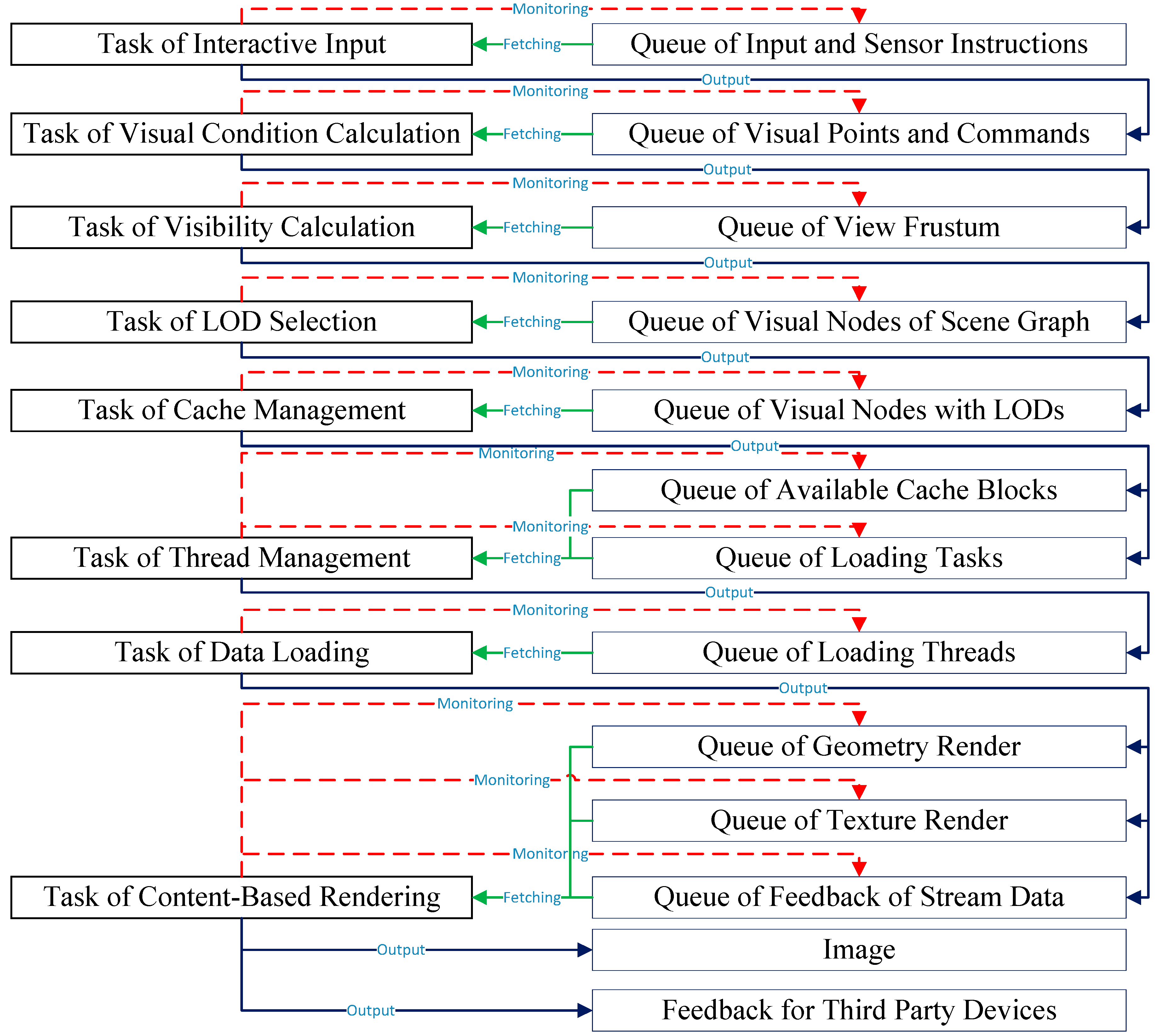
This paper proposes a collaborative model based on sharing the data list during the processing of queue data of each stage. A data queue which can be operated in parallel is set up according to the relationships between the input and output data quantity of the consequent tasks in the pipeline. The previous tasks write the results to the queue once it finishes the job, and the following task monitors the states of the queue. That is, once the data signals change, the task operates the data as input parameters to finish the process and then passes the results as the new input parameters to the queues of the following tasks. The shared queue of different tasks is ensured to be read and written consistently by a muted value in globe. The processing of all the tasks and shared queues is shown in
Figure 3. The task of interaction input monitors the queue of interactive operation and sensor instructions to get the input data. When it finishes the jobs, the output is written to the queue of the visual point and commands. The task of visual condition calculation obtains the input data from the queue of visual point and commands, uses the visible frustum viewpoint coordinates to calculate the view frustum parameters, and writes the result to the queue of the view frustum. The task of visibility calculation monitors the queue of the view frustum to obtain a new frustum, and a visible list of scene graph nodes can be written to the queue of visible scene nodes of the scene graph by the complex process of visibility calculation. The task of LOD selection grabs the data to perform the calculation of LOD parameters for each visible scene graph nodes, and finally the outputs are written to the queue of visible nodes with LODs. The task cache management uses the LOD parameters and the visible scene graph nodes to calculate the desired buffer size and allocate the suitable blocks to the queue of available cache blocks. At the same time, the data lists should be loaded and written to the queue of data loading tasks. The task of thread management generates a thread job by binding the data loading to the target cache block with a thread, and then writes the job to the queue of loading threads. The task of data loading monitors the changes and then employs a different thread to load the data. According to the data type of geometry data, texture data, and stream data of sensors, the data content will be stored to different queues by the data types. Lastly, the task of content-based rendering monitors the changes of the queues, completes the drawing and feedback sessions, displays the result image on a screen, and sends the feedback through the sensors.
The unbalanced computational complexity and data-dependent accessibility issues between frames can cause asynchronous operation in each frame during the real-time rendering. Therefore, a synchronization control is needed to make the data and processing balanced for inner-frame and intra-frames. We designed a task parallel collaborative model based on the shared data queue.
Figure 4 shows the tasks and the queue synchronization process. When the frame starts, an operation named inner-frame synchronization synchronizes all the queues. The data items in the queue will be tagged, which represents the previous frame. It makes sure that the newest items in the queue have the priority to be processed first during the current frame. Each task monitors the data change of the related queue and obtains the correct result for the current frame based on the principle of Last In First Out (LIFO). It achieves frame synchronization and collaboration by allocating the threads to process the data in queues.
Because the different visual conditions between frames cause differences in computational complexity and amounts of data, the current frame may not be able to complete the process for all the items in the queue. This paper proposes a collaboration method to dynamically adjust the number of threads based on the amount of data between frames. At the beginning of the new frame, the task receives a frame synchronization signal, and the processing thread is set to the intra-frame processing thread. If more data need to be processed, the task will apply a new inter-frame processing thread from the thread pool to monitor the data changes of the queue. While the current frame processing threads are in a monitoring state, we do not need to apply a thread from the thread pool, but to just set the jobs of the tasks to the current thread. After the intra-frame processing threads complete the tasks, the frame number tag will be added to the output data. It will process directly if the associated tasks obtain the result from the intra-frame and the current inner-frame processing threads hold the waiting state. While the inner-frame thread is currently in execution, it will check whether there is an intra-frame processing thread. If it exists, the tasks will bind to the intra-frame processing thread. If the intra-frame processing thread returns to the thread pool, the jobs of the tasks will be added to the ends of the queue and will wait for the inner-frame processing threads until one thread becomes idle. If the difference between the output tagged frame and the current frame is more than three, it should apply a new processing thread for the intra-frame to process the current task data. The adaption of threads in frame or between frames can maintain a balance in the consistency of frame rates.
5. Experiments and Results
In this section, we discuss the development of a walk-through navigation program to test the proposed methods. The implementation of the application was a desktop program using VC++. The dataset of the urban city we used comes from the surveying and mapping department of the government, which is not public.
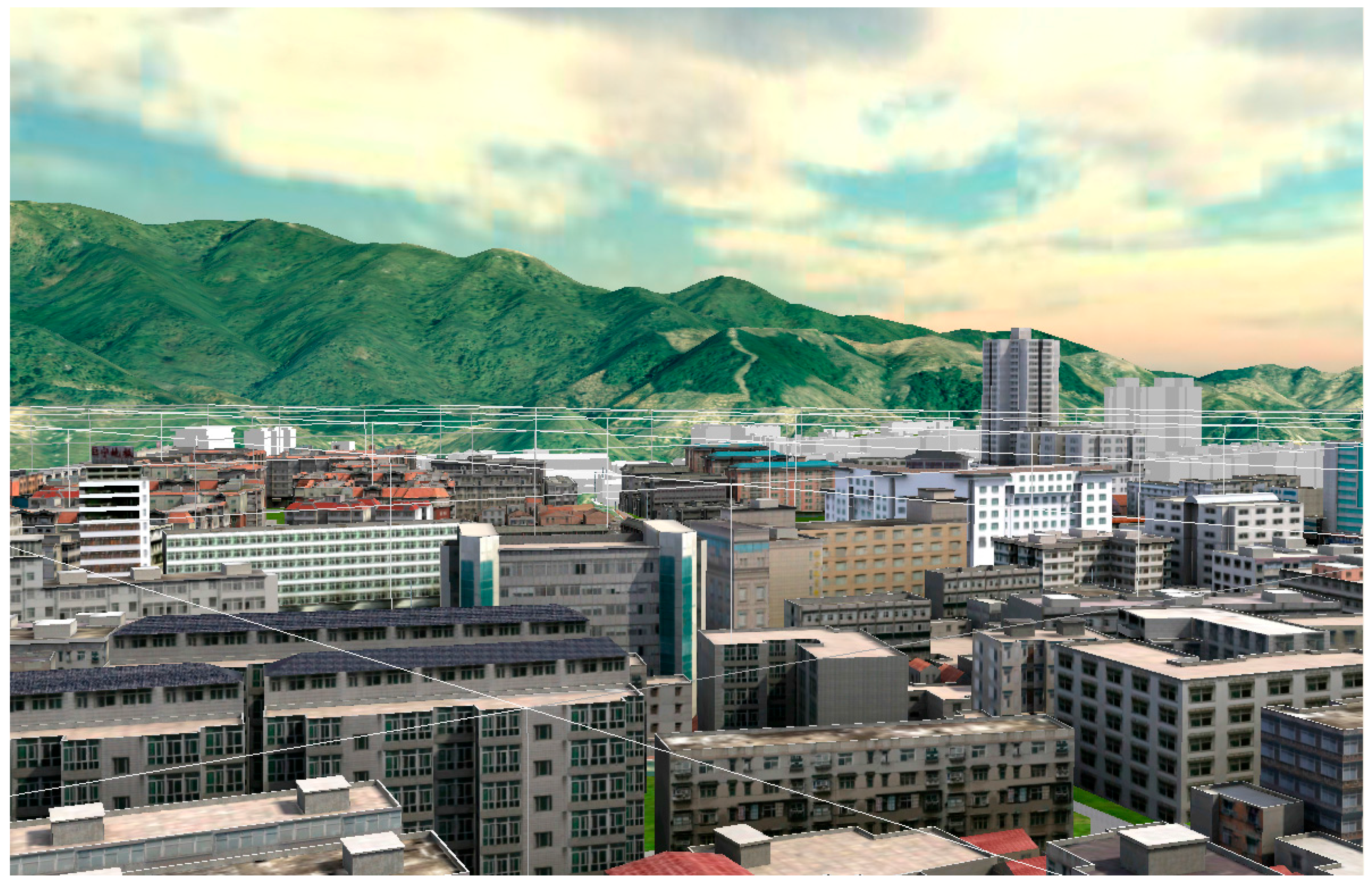
Figure 5 shows part of the test scenario. The test program realized inter-frame synchronization and intra-frame collaboration by using multiple threads to perform the tasks. The number of threads was based on the input-output dependency relationship between adjacent tasks. We chose a walking path, which could access almost any part of the test area, and two different viewpoint positions were selected to extrude the operand of the tasks.
Dataset description: the test dataset includes DEM and DOM for terrain surfaces and 3D models with fine textures for urban buildings, real-time camera stream data for security monitoring, and graphs and annotations for information demonstration. We use the bounding box to represent the object and construct a 3D R-tree as the spatial index, which is the main structure for constructing the scene graph. Each leaf node of the scene graph represents one feature of the scene and includes the geometric data in the form of cuboid, so the cost of operation on each node is equal. In this paper, we do not take the efficiency of the traveling of the scene graph into account because we hold all nodes of the tree in memory and detect no perceived difference in the test. The test area is approximately 10 square kilometers, and the total data volume is approximately 2.9 GB.
We take the following steps for the test:
(1) We converted the original data into a scene graph and restored the data according to the node structure of the spatial index. The geometry data and the texture data were organized by a coherence organization method [
26].
(2) We set up two view point positions to evaluate the operand of each tasks during the runtime, measured the running time of the tasks, and then used the operand and the running time to obtain a ratio for every task. Starting from the first task, we used the ratio of the adjacent tasks to determine the number of threads for every task in the pipeline.
(3) We used three modes to navigate in the same path and record the frames per second (FPS), the number of objects under the view point of every extrude frame. Then, we drew graphs to compare the results of different methods.
In
Table 1, the operand of the task of interactive input (TII) is the number of instructions. The operand of the task of visual condition calculation (TVCC) and the task of visibility calculation (TVC) is the arithmetic computing times by the geometry of the nodes and visual box. The operand of the task of LOD selection (TLS) is the number of operations performed in the CPU. The operand of the task of cache management (TCM) is expressed as the number corresponding to operations management. The operand of the task of thread management (TTM) is the loading and binding operate times. The operand of the task of data loading (TDL) is expressed as the amount of the data that should be loaded, and the value is the data size. The operand of the task of content-based real-time rendering (TCBR) is the sum of the number of vertices and the number of the pixels of the texture tiles.
We obtained a quantity ratio for adjacent tasks by measuring the running time for each task. Because the ratios of different tasks were significantly different, we set up a model to normalize them into a unit that can be performed by threads.
Table 2 shows the results.
In this test, we used two different viewpoint positions to measure the operand and then set the different number of threads. The task of interactive input (TII), the task of visual condition calculation (TVCC), the task of LOD selections (TLS), the task of cache management (TCM), and the task of thread management (TTM) were performed by one thread each. The task of visibility computation (TVC) and the task of content-based real-time rendering (TCBR) used two threads each and the task of data loading was run in four threads. In view 2, TTI, TLS, TCM, and TTM were in the same situation and used only one thread, TVCC used two threads, TVC used four threads, TDL used six threads, and TCBR used three threads. We obtained a ratio between the operands and the running time for the task and started from the first task to set the number of threads for adjacent tasks. The number of threads for each task may have differed in different frames. We employed a thread pool to avoid the frequent allocation and deletion of threads for efficiency. We should note that we set up a satiable thread for each real-time sensor steam data. In our test, one thread for the camera monitored steam data rendering.
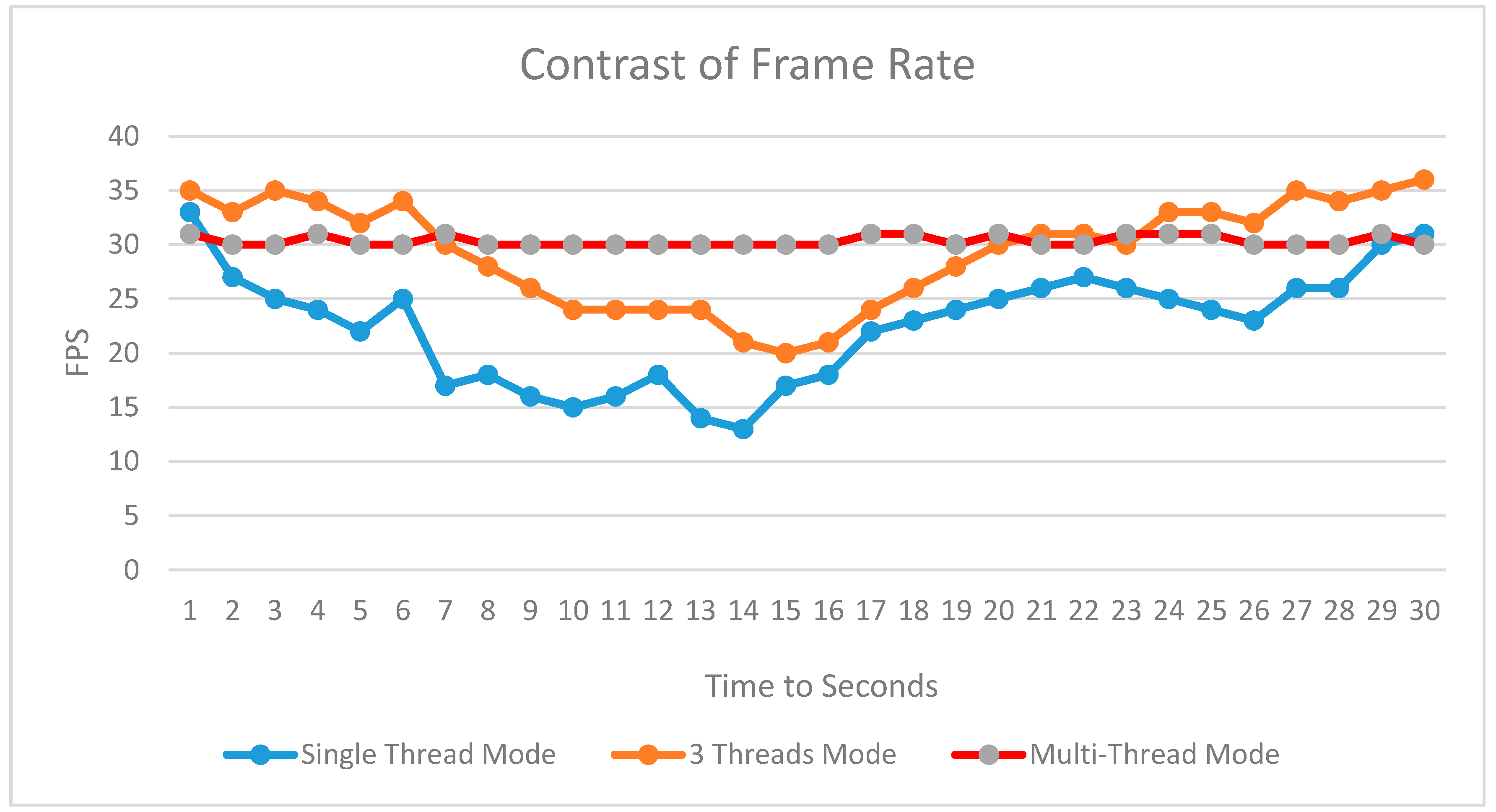
Figure 6 shows the real-time rendering frame rate over 30 seconds for the same roaming path using three methods. Mode (1) is the single-threaded mode, mode (2) is the three threads mode with one thread for data loading, drawing, and other tasks, and mode (3) is the inter-frame and intra-frame multi-thread synchronization mode. A significant frame rate change exists between mode (1) and mode (2) because of the large number of visual objects under the different viewpoint position. The frame rate of mode (2) is higher than that of mode (1), mainly due to the small impact of loading thread to the drawing thread, which is caused by the rendering process not waiting for the finish of the data loading process. In mode (3), the frame rate for rendering is relatively stable; here the frame rate is set to 30 FPS. The frame rates are important for the walking-through applications. However, the number of the drawn objects under the frame rates is more important because it demonstrates the ability of the rendering system. The more objects that can be drawn with the higher frame rates, the better the system is.
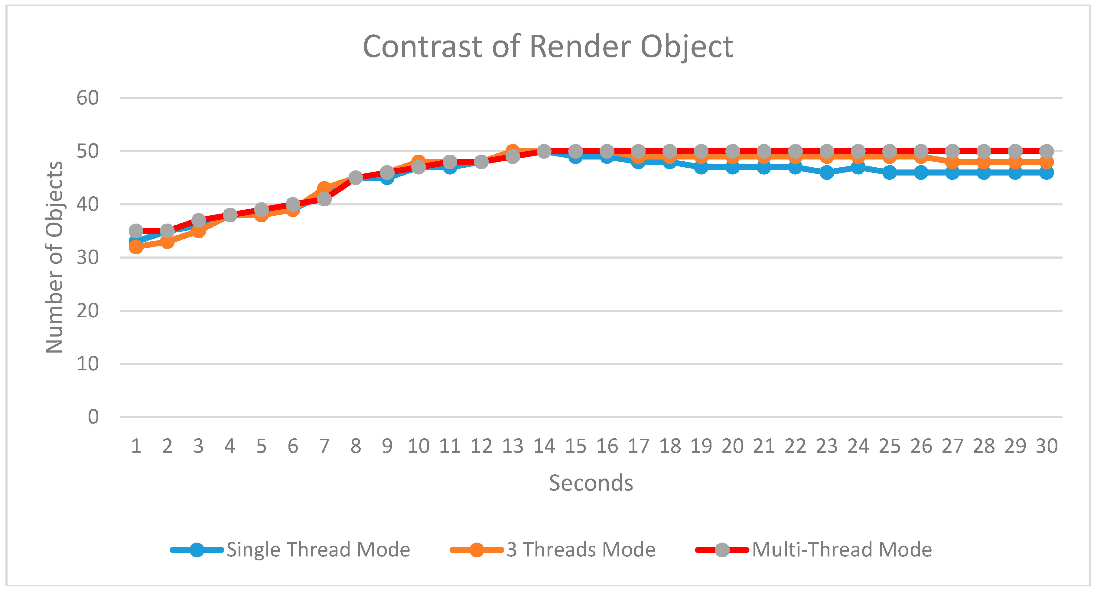
Figure 7 lists the drawn objects during each frame for the above three modes. The curves show the average number of drawn objects during each frame in every second. The number of curves for the three modes is shown in different colors, with mode (1) in blue, mode (2) in brown, and mode (3) in red.
Figure 7 compares the number of drawn objects in different modes. The frame rate between mode (1) and (2) changes significantly when the number of drawn objects increased rapidly, while mode (3) maintains a stable frame rate because of the steady increase in the number of objects. As we can see in
Figure 7, at some time point (e.g., the eighth second) the number of objects drawn in mode (3) is slightly less than that in mode (1) and mode (2). The reason for this is that by using the cache management in the mode (3), the data volume of drawn objects reaches the maximum size of the cache, as such, no more objects can be added into the cache, and all the objects remain stable in the cache. For mode (1) and mode (2), it should be noted that we did not take the real-time sensor steam data into account, because the scene drawing stops if the rendering thread is taken by the steam processing.
6. Conclusions
In this paper, the basic procedures of the real-time visualization of urban 3DGIS were first reviewed, and the real-time visualization pipeline was analyzed. Then, the pipeline was broken down into different stages. Furthermore, we analyzed the arithmetic computing algorithms of the tasks and the input-output dependency between adjacent tasks in the pipeline. We first used the operand to represent the cost of the task and measure the real-time running time to obtain the ratio of time to operand. Then, we started from the first task of the pipeline to evaluate the process unit numbers to every two adjacent tasks. Based on the analysis of the task parallelism in different pipeline stages, the data parallelism characteristics in every task were summarized by studying the involved algorithms. We used the sharing queue mode to collaborate the inter-frame tasks of the pipeline and synchronize the balance of the intra-frame tasks. By implying a dynamic adjustment in threads, we were able to achieve the data synchronization for inter- and intra-frame and collaboration in tasks during the real-time visualization. A theoretical foundation for task parallel and data parallel processing modes was built for high-performance processing in the real-time visualization of urban 3DGIS.
With the development of the widely applied virtual reality and augmented reality (VR/AR), the real-time rendering of virtual reality scenes with a 3D environment has become a hot issue. The method proposed in this paper can be adapted to the VR/AR visualization of urban 3DGIS. In addition, it is also suitable for the common displays of images. It is not involved in existing VR and AR visual computing devices, such as VR/AR glasses and other terminal equipment, which have restrictions in cache and computer power. For the practical application of VR and AR, the rendering method and feedback methods should be expanded further.
Acknowledgments
This research is financially support by the National Natural Science Foundation of China (Nos. 41671377; 41501463; 41571392; 61501198; 41301434; 41201413), the research funds of CCNU from the colleges’ basic research and operation of MOE (CCNU16A02021), Specific funding for education science research by self-determined research funds of CCNU from the colleges’ basic research and operation of MOE (CCNU16JYKX016), National Science and Technology Support Project (No.2015BAH33F02), the National Key Technologies Research and Development Program of China under Grant 2016YFB0502604 and Wuhan Youth Science and Technology Chenguang program under grant 2014072704011248.
Author Contributions
Dongbo Zhou, Gang Jiang, Jie Yu, Leyuan Liu, and Wenbo Li worked collectively. Specifically, Dongbo Zhou proposed the original idea, Gang Jiang and Jie Yu analyzed the data, Leyuan Liu and Wenbo Li conceived and designed the experiments, and Dongbo Zhou and Jie Yu wrote the paper. All of the co-authors drafted and revised the article collectively, and all authors have read and approved the final manuscript.
Conflicts of Interest
The authors declare no conflict of interest.
References
- Xiao, L.; Zhong, E.; Liu, J. A discussion on basic problems of 3D GIS. J. Image Graph. 2001, 6, 842–848. [Google Scholar]
- Zhu, Q. Thinking of the progress in 3D GIS technologies. Geomat. World 2004, 2, 6–7. [Google Scholar]
- Kasik, D.; Dietrich, A.; Gobbetti, E.; Yoon, S. Massive Model Visualization Techniques; ACM Press: Los Angeles, CA, USA, 2008. [Google Scholar]
- Akenine-Moller, T.; Haines, E.; Hoffman, N. Real-Time Rendering, 3rd ed.; A. K. Peters Ltd.: Natick, MA, USA, 2008; p. 1027. [Google Scholar]
- Funkhouser, T.A.; Sequin, C.H. Adaptive Display Algorithm for Interactive Frame Rates During Visualization of Complex Virtual Environments; ACM Press: Anaheim, CA, USA, 1993; pp. 247–254. [Google Scholar]
- Aliaga, D.; Cohen, J.; Wilson, A.; Baker, E.; Zhang, H.; Erikson, C.; Hoff, K.; Hudson, T.; Stuerzlinger, W.; Bastos, R.; et al. MMR: An Interactive Massive Model Rendering System Using Geometric And Image-Based Acceleration; ACM Press: Atlanta, GA, USA, 1999; pp. 199–206. [Google Scholar]
- Correa, W.T.; Klosowski, J.T.; Silva, C.T. iWalk: Interactive out-of-core rendering of large models. In Technical Report TR-653-02; Princeton University: Princeton, NJ, USA, 2002. [Google Scholar]
- Yoon, S.; Salomon, B.; Gayle, R. Quick-VDR: Out-of-core view-dependent rendering of gigantic models. IEEE Trans. Vis. Comput. Graph. 2005, 11, 369–382. [Google Scholar] [CrossRef] [PubMed]
- Borgeat, L.; Godin, G.; Blais, F. GoLD: Interactive display of huge colored and textured models. ACM Trans. Graph. 2005, 24, 869–877. [Google Scholar] [CrossRef]
- Yang, J. AnyGL: A Larger Scale Hybrid Distributed Graphics System. Doctor’s Thesis, Zhejiang University, Hangzhou, China, 2002; p. 145. [Google Scholar]
- Zheng, X.; Liu, W.; Lu, C. Real-time dynamic storing and rendering of massive terrain with GPU. J. Comput.-Aided Design Comput. Graph. 2013, 25, 1146–1152. [Google Scholar]
- Yan, C.; Yue, T. GPU accelerated high accuracy surface modeling methods for DEM Modelling. Comput. Eng. Appl. 2012, 48, 22–27. [Google Scholar]
- Song, X.; Dou, W.; Tang, G. Research on data partitioning of distributed parallel terrain analysis. J. Natl. Univ. Defense Technol. 2013, 1, 130–135. [Google Scholar]
- Wan, L.; Huang, Z.; Peng, X. An effective NoSQL-based vector map tile management approach. ISPRS Int. J. Geo-Inf. 2016, 5, 215. [Google Scholar] [CrossRef]
- Xu, X.; Li, J.; Jing, N. Real-time visualization of 3D city models based on CityGML. J. Syst. Simul. 2012, 24, 1243–1246. [Google Scholar]
- Xie, J.; Huang, X. Orthorectification of IKONOS and impact of different resolution DEM. Geo-Spat. Inf. Sci. 2012, 9, 108–111. [Google Scholar]
- Guo, H.; Li, X.; Wang, W.; Lv, Z.; Xu, W. An event-driven dynamic updating method for 3D geo-databases. Geo-Spat. Inf. Sci. 2016, 19, 140–147. [Google Scholar] [CrossRef]
- Gao, J.; Liu, P.; Kang, X.; Zhang, L.; Wang, J. PRS: Parallel relaxation simulation for massive graphs. Comput. J. 2016, 59, 848–860. [Google Scholar] [CrossRef]
- Li, R.; Fan, J.; Wang, X.; Zhou, Z.; Wu, H. Distributed cache replacement method for geospatial data using spatiotemporal locality-based sequence. Geo-Spat. Inf. Sci. 2016, 18, 171–182. [Google Scholar] [CrossRef]
- Li, D. 3D visualization of geospatial information: Graphics based or imagery based. Acta Geod. Cartogr. Sin. 2010, 2, 111–114. [Google Scholar]
- Shu, H. Big data analytics: Six techniques. Geo-Spat. Inf. Sci. 2016, 19, 119–128. [Google Scholar] [CrossRef]
- Wang, L.; Chen, D.; Deng, Z.; Huang, F. Large scale distributed visualization on computational Grids: A review. Comput. Electr. Eng. 2011, 37, 403–416. [Google Scholar] [CrossRef]
- Shreiner, D.; Sellers, G.; Kessenich, J.; Licea-Kane, B. The Khronos OpenGL ARB Working Group. In OpenGL Programming Guide: The Official Guide to Learning OpenGL, Version 4.3 (8th Edition) (OpenGL); Addison-Wesley Professional: New York, NY, USA, 2013; p. 986. [Google Scholar]
- Buss, S.R. 3-D Computer Graphics: A Mathematical Introduction with OpenGL; Cambridge University Press: New York, NY, USA, 2003; p. 397. [Google Scholar]
- Zhang, Y. An Adaptive Visualization Method of 3D City Models. Doctor’s Thesis, Wuhan University, Wuhan, China, 2008; p. 124. [Google Scholar]
- Li, W.; Du, Z.; Ling, F.; Zhou, D.; Wang, H.; Gui, Y.; Sun, B.; Zhang, X. A Comparison of land surface water mapping using the normalized difference water index from TM, ETM+ and ALI. Remote Sens. 2013, 5, 5530–5549. [Google Scholar] [CrossRef]
© 2017 by the authors. Licensee MDPI, Basel, Switzerland. This article is an open access article distributed under the terms and conditions of the Creative Commons Attribution (CC BY) license ( http://creativecommons.org/licenses/by/4.0/).


