Article

Geospatial Analysis of Earthquake Damage Probability of Water Pipelines Due to Multi-Hazard Failure

by
Mohammad Eskandari
1,*,
Babak Omidvar
2,
Mahdi Modiri
1,
Mohammad Ali Nekooie
1 and
Ali Asghar Alesheikh
3
1
Department of GIS, Malek Ashtar University of Technology, 15875-1774 Tehran, Iran
2
Department of Environmental Engineering, Graduate Faculty of Environmental, University of Tehran, 14155-6135 Tehran, Iran
3
Department of GIS, K.N. Toosi University of Technology, 19967-15433 Tehran, Iran
*
Author to whom correspondence should be addressed.
ISPRS Int. J. Geo-Inf. 2017, 6(6), 169; https://0-doi-org.brum.beds.ac.uk/10.3390/ijgi6060169
Submission received: 24 March 2017 / Revised: 24 April 2017 / Accepted: 15 May 2017 / Published: 9 June 2017

Abstract

:
The main purpose of this study is to develop a Geospatial Information System (GIS) model with the ability to assess the seismic damage to pipelines for two well-known hazards, including ground shaking and ground failure simultaneously. The model that is developed and used in this study includes four main parts of database implementation, seismic hazard analysis, vulnerability assessment and seismic damage assessment to determine the pipeline’s damage probability. This model was implemented for main water distribution pipelines of Iran and tested for two different earthquake scenarios. The final damage probability of pipelines was estimated to be about 74% for water distribution pipelines of Mashhad including 40% and 34% for leak and break, respectively. In the next step, the impact of each earthquake input parameter on this model was extracted, and each of the three parameters had a huge impact on changing the results of pipelines’ damage probability. Finally, the dependency of the model in liquefaction susceptibility, landslide susceptibility, vulnerability functions and segment length was checked out and specified that the model is sensitive just to liquefaction susceptibility and vulnerability functions.

1. Introduction

Over the past decades, casualties due to natural disasters have increased in the world. One of the most important natural disasters is the earthquake, the neglecting of which leads to irreparable damages [1]. Iran’s position on the Alpine-Himalayan seismic belt puts this country among one of the world’s earthquake-prone countries, and according to geological studies, about 97% of Iran’s cities and villages are subjected to earthquake danger [2]. In these earthquakes, most damages are related to critical infrastructures; and the study of the damages’ history due to the world’s destructive earthquakes indicates the importance of lifelines’ failure’s share of the losses. For example, in the San Fernando earthquake, although there were structural damages, the major damages were related to lifelines’ damages, especially pipelines and bridges [3].
Lifelines are crucial lines for the survival of urbanization in the modern world. These lifelines are used to produce and distribute goods and services in urban units, and life possibility in cities depends on the quality and the quantity of these lifelines’ function. In the case of cities, supply, transmission and distribution of water play an important role, and the water systems are considered as critical infrastructures of any society, since they are directly related to the vital and basic needs of society’s population. Regarding the high prevalence and the wide range of affected people, the damage to the main water distribution pipelines would have great potential for creating massive crises in the society. In other words, small and short-time fluctuations in the main water distribution pipelines’ service have wide effects on the performance of the entire urban water distribution network.
The vulnerability of pipelines against disasters is the subject of many studies these days, as the damages to these infrastructures not only is a part of damages, but also can complicate the disasters of other damages and significantly affect the recovery period. Various parameters, such as Peak Ground Acceleration (PGA), Peak Ground Velocity (PGV) and Permanent Ground Displacement (PGD) should be calculated to determine the vulnerability. In lifeline damage analysis, providing spatial information at different levels, such as geological maps, topography maps and lifelines’ network of critical infrastructures, is more important than before. Spatial information science according to the Geospatial Information System (GIS) is a method for computerized organization of spatial data that creates a backup system for disaster management by spatial analysis [4].
According to this, the damages to pipelines (especially water pipelines) in the past earthquakes are reviewed, and various studies for pipelines’ failure estimation done in the world will be investigated. Afterward, the methodology for damage probability analysis is presented in detail, step by step. It should be noted that the most important limitation of this model is the use of empirical equations to estimate the vulnerability of pipelines that have been used for damages of the previous earthquake. In order to test our model, two different seismic scenarios for the water distribution pipelines of Mashhad city are evaluated. In the following, a sensitivity analysis is performed to find the most effective parameters on pipelines’ failure, and finally, the research conclusion is discussed.

2. Literature Review

The evaluation of the results and negative effects of past earthquakes is a good starting point in order to perform different actions to increase the level of networks’ security. The earthquakes occurring in the past years have imposed irreparable damages to pipelines, but there is not enough information and statistics about earthquake damages and the damages to pipelines in the cities. The most important damages to water pipelines from past earthquakes can be summarized as follows [5]:
  • Philippines Mindanao earthquake (1976): a part of the main city water supply pipe was broken due to the collapse of a bridge on the pipelines.
  • El Salvador earthquake (1986): about 80 km of water pipes (20% of total pipelines) and about 65 km of sewage pipelines (22% of total sewage pipelines) were severely damaged. In this earthquake, a part of steel pipe was deformed and tilted.
  • Venezuela Caracas earthquake (1997): drinking water supply pipelines, which had 30 degrees along the fault, were severely damaged. Buried pipelines in soil and sewage treatment installations were damaged, as well.
  • Bam earthquake (2003): in this earthquake, 11 wells were damaged, and six points of the main pipes in central areas of the city were seriously damaged.
After several studies and reviews on the effects of earthquake damage on the pipelines, it can be concluded that damage to the pipelines caused by ground shaking and ground failure needs more attention and research. The ground failure will emerge as three types: faulting, landslide and liquefaction. Furthermore, liquefaction failure is divided into two categories as ground settlement and lateral spreading [6]. The ground shaking and ground failure also are known as primary and secondary earthquake damages, respectively. Generally, pipes are under the combined effects of both types of hazards; so that O’Rourke and Deyoe [7] indicated that almost half of the pipe failures in the San Francisco earthquake in 1906 were due to the lateral spread process of liquefaction, and the other half of the damages occurred due to waves crossing and seismic moments in a larger region. Hence, it is very important to provide appropriate vulnerability functions in damage assessment.
A number of pipeline damages from six different earthquakes (four of them in Japan, one in Nicaragua and the last one in the United States) are studied by Katayama et al. [8] to estimate the fragility relations for both Asbestos Cement (AC) and segmented Cast Iron (CI) pipelines in terms of PGA. In this study, three different soil conditions, poor, average and good, were considered in fragility relations analysis. Barenberg [9] published the first PGV-based fragility relation for buried CI pipelines in the late 1980s using the data received from three different earthquakes in the U.S.
A comprehensive study on seismic loss estimation for water resource systems was published by ASCE in 1991 [10]. In this study, PGA-based fragility relations were calculated using the collected damage data by Katayama et al. [8] and the Coalinga pipeline damage in 1983. In another study, a new pipeline fragility relation in terms of PGV was presented by O’Rourke and Ayala [11] based on the damage data of Barenberg [9], as well as the available damage information from three other earthquakes in the U.S. It is important to note that the presented fragility relation by O’Rourke and Ayala [11] has been used in the loss assessment methodology HAZUS-MH of FEMA [6]. A few years later, a new GIS-based method was introduced by O’Rourke et al. [12] to examine various factors that affect the Los Angeles Department of Water and Power (LADWP) and the Metropolitan Water District (MWD) water supply services after the Northridge earthquake in 1994. In this research, seven seismic parameters including PGA, PGV, PGD, Modified Mercalli Intensity (MMI), Arias Intensity (AI), Spectral Acceleration (SA) and Seismic Intensity (SI) are used to study the relationship between the earthquake repair rate and the seismic intensity. In addition to that, the fragility relations for pipelines also were assessed in terms of MMI, SI, PGA and PGV. O’Rourke et al. [12] concluded that the best-related factor to the pipeline damage is PGV, and hence, the PGV-based fragilities are proposed for steel, CI, Ductile Iron (DI) and AC pipelines.
In another study, a set of algorithms is presented by the American Lifeline Alliance (ALA) to compute the probability of earthquake damage that affects various components of water supply systems [13]. The analyses of water resources’ pipeline damages related to earthquakes are continued by Pineda-Porras and Ordaz-Schroeder [14] using the data from the Michoacan earthquake (1985) in Mexico City. A detailed PGV map is used to find the best relationship between repair rate and seismic intensity. The results showed that a PGV-based fragility relation is the best option for Mexico City’s water system [15].
As can be seen, various studies and relationships were presented along with several experimental vulnerability functions in the name of the equilibrium of repair rate per kilometer for earthquake damage analysis. Table 1 shows the relationships between various vulnerability functions and earthquake data used. In addition to that, strong-motion parameters considered by each study are shown in this table [16].
Moreover, several studies about pipelines’ vulnerability assessment have been performed to provide the vulnerability relationships. Rahnama et al. [17] assessed the seismic vulnerability of 11 regional water distribution networks in the city of Tehran. In this study, the uncertainty caused by the earthquake was not considered, and just the damages to the water distribution network were evaluated. The most important results of the study indicated that all 11 regional water distribution network would not face a lot of damages, and just some parts of inflexible pipes with a small diameter would have a problem if the North Tehran Fault activates.
Omidvar et al. [3] presented a model for buried fuel pipelines, and after the determination of the earthquake scenario, the repair rate of the pipeline and the number of fires due to the earthquake around the pipeline were estimated. The model just evaluated the hazards of ground shaking, as the liquefaction probability in this area was extremely low.
Eskandari et al. [4] presented a model in order to analyze the seismic damage of critical infrastructures according to a geospatial information system. The model included both types of hazards (ground shaking and the ground failure), and also the uncertainties at a reasonable level are considered. However, the model was used only for hard and heavy components of lifelines (such as refinery, substation, water pumping stations, etc.), and it cannot be used for pipelines’ evaluation.
The differences between this study and current literature in this field briefly are:
  • Although some studies use the geospatial information system in order to analyze pipelines’ damage, more evaluation was based on the instrumental view and multi-criteria decision making process than paying attention to simultaneous spatial assessments.
  • In most previous studies in this field, both types of hazards (ground failure and ground shaking) are not considered simultaneously after an earthquake, while here, both types of hazards are considered and combined appropriately with each other.
  • In some studies, the pipeline repair rate just was evaluated on the basis of experimental relationships, and the earthquake position in a pipeline is unknown, while the presented model estimates the position of damage with a high percentage.
  • Uncertainty analysis is another issue in the current literature, while earthquake analysis always comes with uncertainties. This study assesses the uncertainties with many repetitions in software and approximates the assessment results to the reality status.
  • By the use of the sensitivity analysis of the model, the study determines the parameters that have many effects on pipelines’ damage that have not been considered in the previous studies.

3. Materials and Methods

According to the complexities in the method of pipelines’ damage assessment, the number of parameters and also the information layers that play an important role in damage analysis, modeling using an appropriate system like the geospatial information system is required. The general algorithm and conceptual model of this software system are shown in Figure 1. It is important to note that the visual studio with C# programming language along with .NET Frameworks and Arc GIS Engine for reading and writing files and processing on spatial data are used in this study. In the following, the required steps for the implementation of the system in the seismic damage assessment of pipelines are explained.

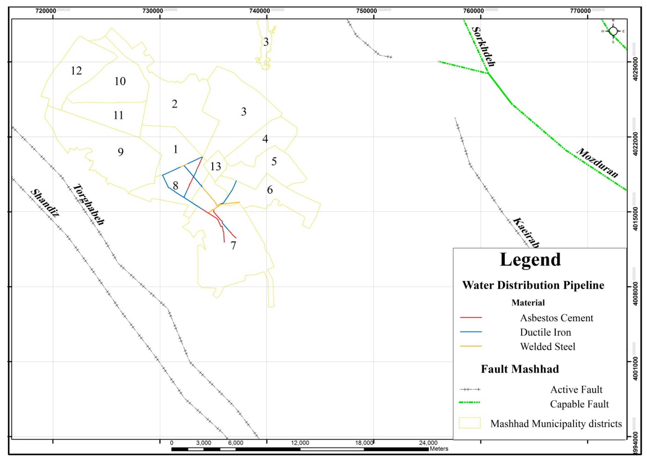
3.1. Case Study and Collecting Data in the Database

The local database filed by the ESRI platform is used in this study because the database should be able to support the spatial data (both vector and raster) and also be able to make a connection with the programming area. In order to implement the existing system and display outputs, a case study is required, so the data of Mashhad city is used in this research.
Mashhad is the second largest city in Iran located in an area between the Kopet Dagh Mountains from north and northeast and the Binalud Mountains from the southwest. Earthquake evaluation of this area shows intensive activities in past centuries, especially in the eighteenth century and then a relatively calm period [18]. The existence of capable and active faults on both sides of the plain near this city show the high potential of earthquake hazard in this area. From east and southeast, this city has about a 20-km distance from a fault and from south and southwest less than 2 km from another fault. In 2007, in the urban complex of Mashhad, 275 micro earthquakes and earthquakes occurred, three of which were above 4.5 on the Richter scale, and the most important was 6.6 on the Richter scale [19]. Therefore, there are capable and active faults around Mashhad, as is shown in Figure 2. The water demand of this city is supplied by 270 deep wells, 5 lime wells and 3 dams (Kardeh, Targh and Doosti). In this study, the damages to the main water distribution pipelines in Zones 7 and 8 of this city due to the earthquake are analyzed. The main water distribution pipelines in Zones 7 and 8 of this city include 9.2 km with asbestos cement, 16.4 km with ductile iron and 6.8 km with welded steel, which provide the water requirements of these two zones.
The main layers of the database in this model include vector layers of water distribution pipelines, the descriptive layer of each pipeline’s specifications, such as pipe material, pipe diameter, etc., the vector layer of faults’ position and historical and instrumental earthquakes around the studied area [20,21], the geology vector layer of the area, such as the vector layers of groundwater depth, deposit type, geological age, slope angle and the groundwater condition, and determining the map of liquefaction susceptibility.

3.2. Seismic Hazard Analysis

The seismic hazard analysis process is an important step in the seismic damage assessment on buildings and lifelines. In this study, the damages caused by both ground shaking and ground failure are analyzed [6], and the following steps are taken:

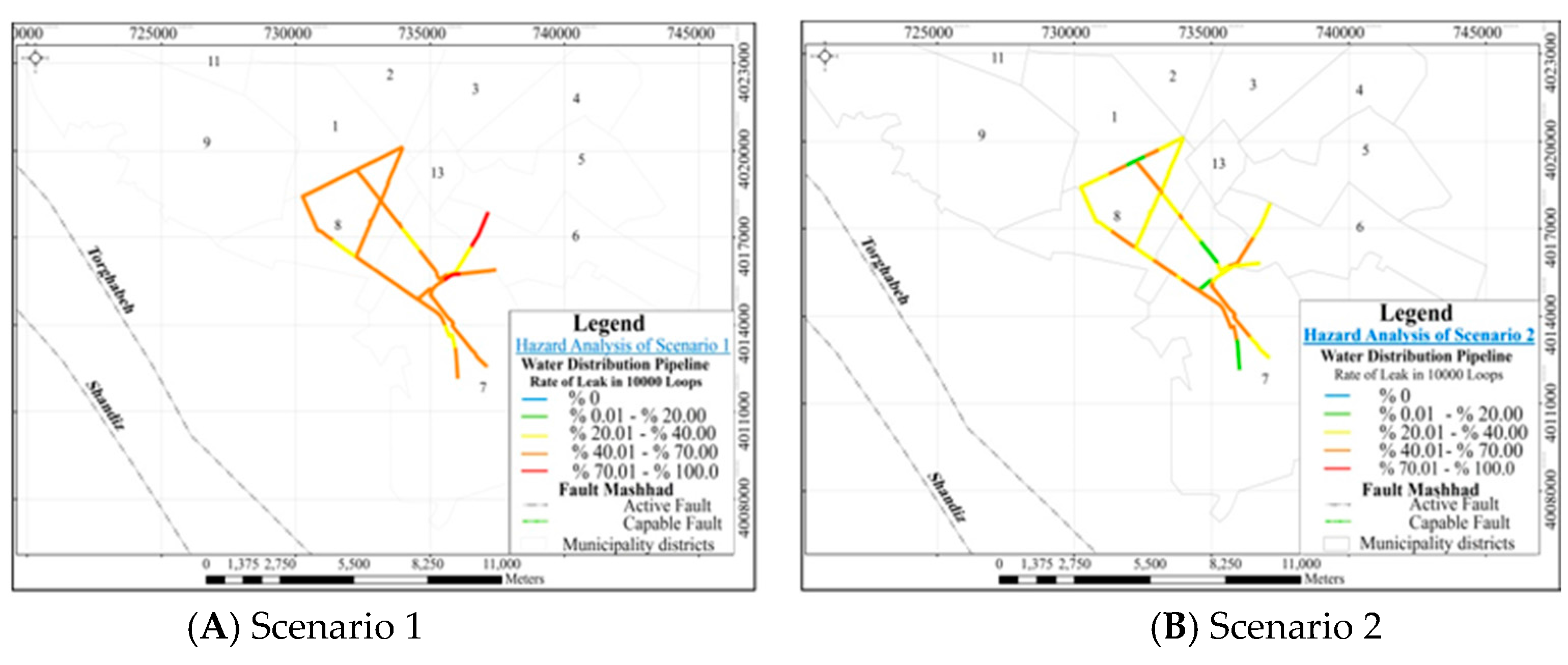
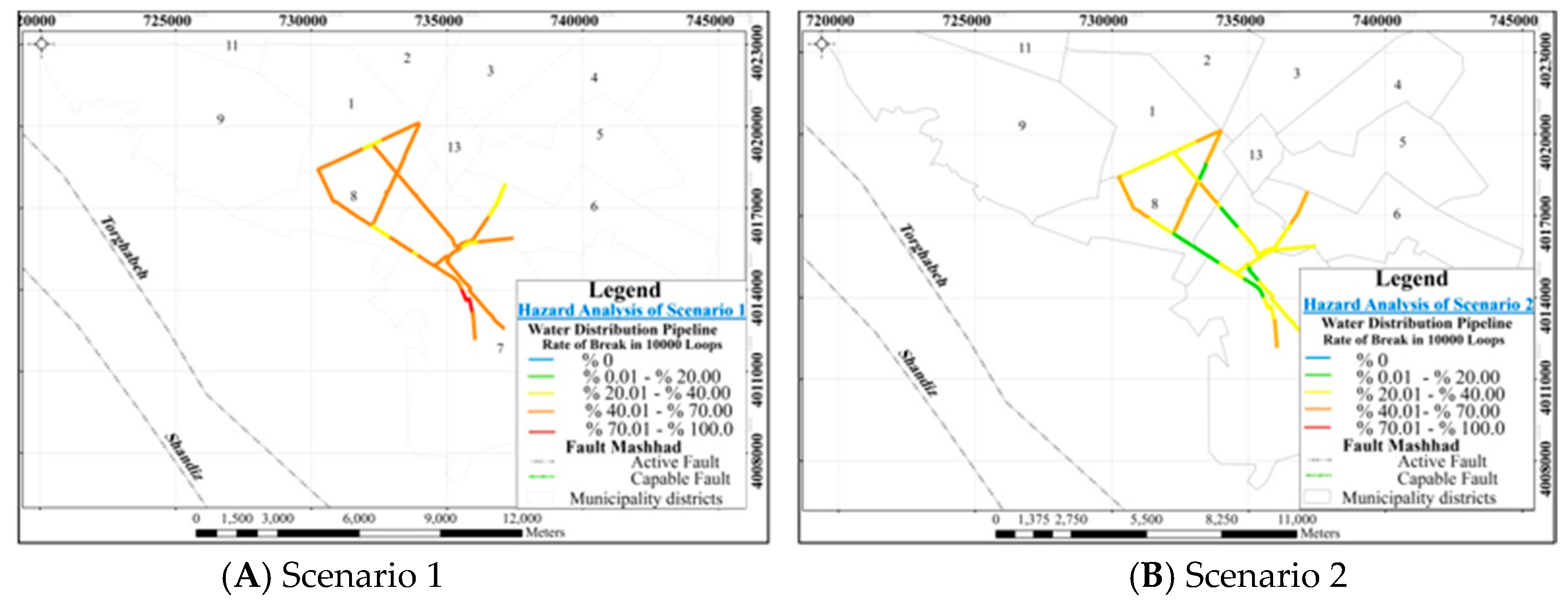
3.2.1. Selection of the Earthquake Scenario

Earthquake scenario selection has an important role in the analysis of outputs, and hence, the values of the earthquake scenario should be considered in a probable and pessimistic manner [22]. Two scenarios are selected for this analysis in which the first one is on an active fault of the area (Figure 2) and the other one is selected randomly.
Scenario 1
(on Shandiz fault): In this step, the maximum magnitude expected for Shandiz fault, which is a strike-slip fault with an 85-km failure length, is determined after preparing the seismic database of the area, according to presented relationships in Table 2. In addition to that, the focal depth is considered according to the average of the historical and instrumental earthquakes around each fault, and the earthquake position is also selected randomly on the Shandiz fault line in each analysis.
Scenario 2
(selected randomly): According to 10 historical earthquakes and 2 instrumental earthquakes between 6 and 7.5 Richter in less than 100 km of the city [23], the random probable magnitude is selected in a range between 6 and 7.5 Richter on the basis of the uniform distribution function. The earthquake focal depth also is chosen in a range between 3 to 25 km because more than 85% of previous earthquakes occurred in this range [23]. In order to determine the coordinates of an earthquake location, an area of the map is selected with a radius of 50 km around the city. The summaries of the two earthquake scenarios are shown in Table 3.

3.2.2. Pipelines Separation into Equal Length to Increase the Accuracy of Analysis

First of all, the pipelines are separated into small segments (1000 m) in order to increase the accuracy of analysis. Then, after recognizing the attenuation relationship and the appropriate vulnerability functions for each probable scenario, the hazard analysis for each segment is performed, and the output parameter values of hazard analysis for both ground shaking and ground failure in each segment of pipe are calculated separately. The main reasons for pipelines’ segmentation are to accurately calculate the distance of each part of the pipe with the earthquake position, and the geological characteristics, as shown in Figure 3, in each small region varies continuously; so if the pipelines have a long length, the extraction of the geological parameters are faced with many uncertainties.

3.2.3. Hazard Analysis of Ground Shaking Based on Attenuation Relationships

The earthquake output parameter can be calculated as a function of earthquake magnitude, the distance between the earthquake source to the site, the site structure conditions and the fault type of the area for each segment of the pipeline, according to the attenuation relationship for each earthquake scenario. In this study, in order to reduce the uncertainties, 3 attenuation relationships including Zare et al. [29], Ghodrati et al. [30], and Campbell and Bozorgnia [31] are used, and the relevant relationships have been coded in the prepared system.

3.2.4. Hazard Analysis of Ground Failure

The ground failure is divided into the three main following categories: liquefaction, landslide, and faulting:
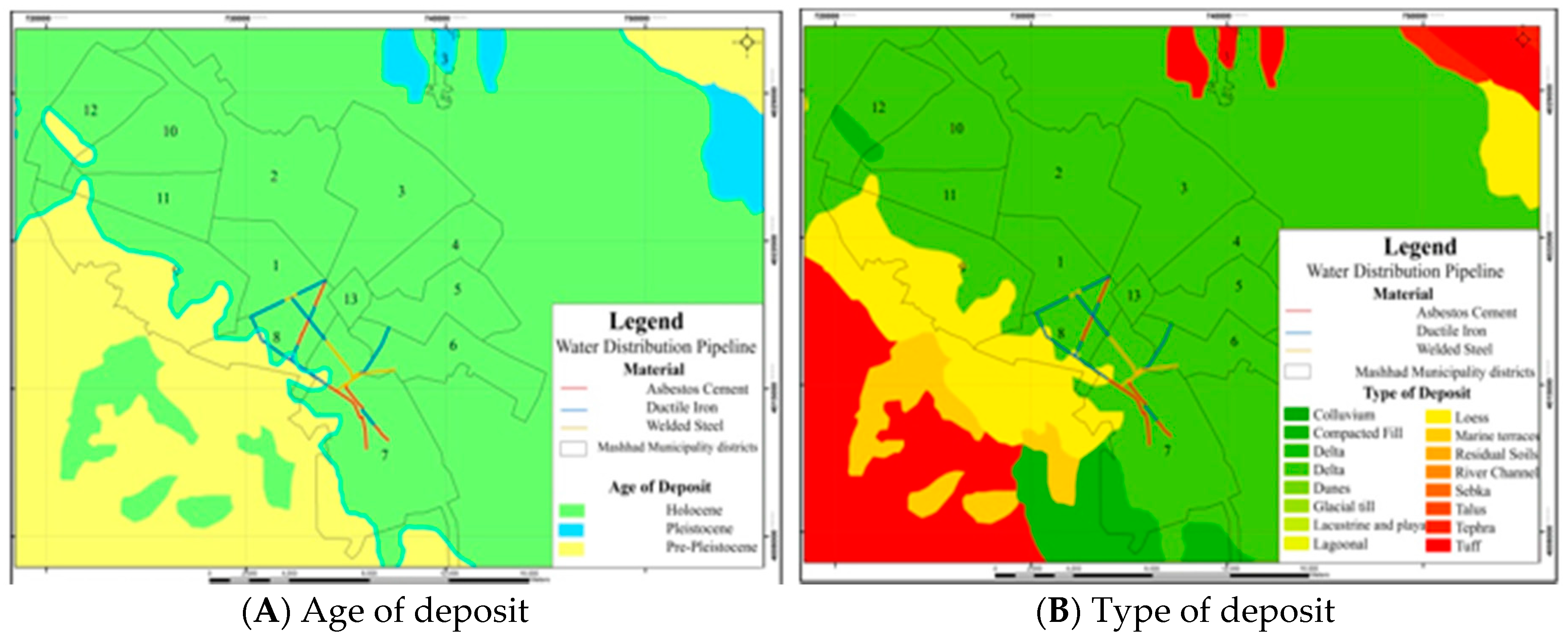
  • Liquefaction is the most important hazard due to ground failure that always threatens the pipelines. In this model, in order to consider the failure caused by soil liquefaction, at the beginning, the geologic map is drawn, and the liquefaction susceptibility of each segment of pipeline is determined. The liquefaction susceptibility of various types of soil deposits is estimated by assigning a qualitative susceptibility rating based on the general depositional environment, the geologic age of the deposit and the material type [32]. Then, the liquefaction probability for each segment of pipeline is calculated. The likelihood of experiencing liquefaction at a specific location is primarily influenced by the susceptibility of the soil, the amplitude and duration of ground shaking and the depth of groundwater. The probability of liquefaction for a given susceptibility category can be determined using the following relationship [6]:
    P   [ Liquefaction   SC ] = P   [ Liquefaction   SC   |   PGA = a ] Km * Kw * P m l
    where P [Liquefaction SC | PGA = a] is the conditional liquefaction probability for a given susceptibility category at a specified level of peak ground acceleration, KM is the moment magnitude correction factor, Kw is the ground water correction factor [33,34] and Pml is the proportion of the map unit susceptible [35].
    At the end, the permanent ground displacement caused by the two liquefaction hazards, lateral spreading and ground settlement is determined [36].
  • The landslide hazard evaluation requires the characterization of the landslide susceptibility of the soil/geologic conditions of a region or sub-region. Susceptibility is characterized by the geologic group, slope angle and critical acceleration [37]. Landslide susceptibility is measured on a scale of 1 to 10. The site condition is analyzed using three geologic groups and groundwater level. The groundwater condition is divided into either dry condition (groundwater below level of the sliding) or wet condition (groundwater level at ground surface). The critical acceleration is then estimated for the respective geologic and groundwater conditions and the slope angle [37]. Furthermore, the percentage of map area having a landslide-susceptible deposit is estimated [38]; and finally, the permanent ground displacements are determined based on the expected displacement correction factor [39], the induced acceleration and the number of cycles [33].
  • The median maximum displacement is estimated based on the earthquake moment magnitude [27].
Finally, the output parameters of ground shaking (PGV and PGD) and the output parameters of ground failure (liquefaction probability, the permanent ground displacement caused by lateral spreading, ground settlement, landslide and faulting) are evaluated for each part of the pipeline.

3.3. Seismic Vulnerability Functions of Pipelines

The vulnerability function is a relationship that expresses the expected failure for a structure as a function of strong ground movement or any other seismic parameter and also can be expressed in different states such as vulnerability relationships and failure curves. Generally, the damage to pipelines is expressed as a function of Peak Ground Velocity (PGV) or Permanent Ground Displacement (PGD) or in the parameter of the Repair Rate (RR) [6]. The repair rate is presented by different models, such as ALA (American Lifeline Alliance) [13], LESSLOSS (Risk Mitigation for Earthquakes and Landslides Integrated Project) [40] and the Federal Emergency Management Agency [6]. In this study, the Federal Emergency Management Agency [6] is used (Table 4). The repair rate relationship due to PGV was formed according to experimental data of O’Rourke and Ayala [11] and on the basis of four observed earthquakes in America and two earthquakes in Mexico, as well as the repair rate relationship due to Permanent Ground Displacement (PGD) was extracted from Honegger and Eguchi [41] results for San Diego.
The RR variable is the repair rate and represents the number of repairs in each kilometer of a pipeline [6]. The pipelines’ damage probability is calculated based on the following experimental relationship (after determination of the repair rate assuming that the number of pipe failures follows Poisson’s distribution) [42]:
p F = 1 EXP   ( R R * L )
In this relationship, L is the pipeline length in km, RR is the pipeline repair rate and Pf is the pipeline failure probability.

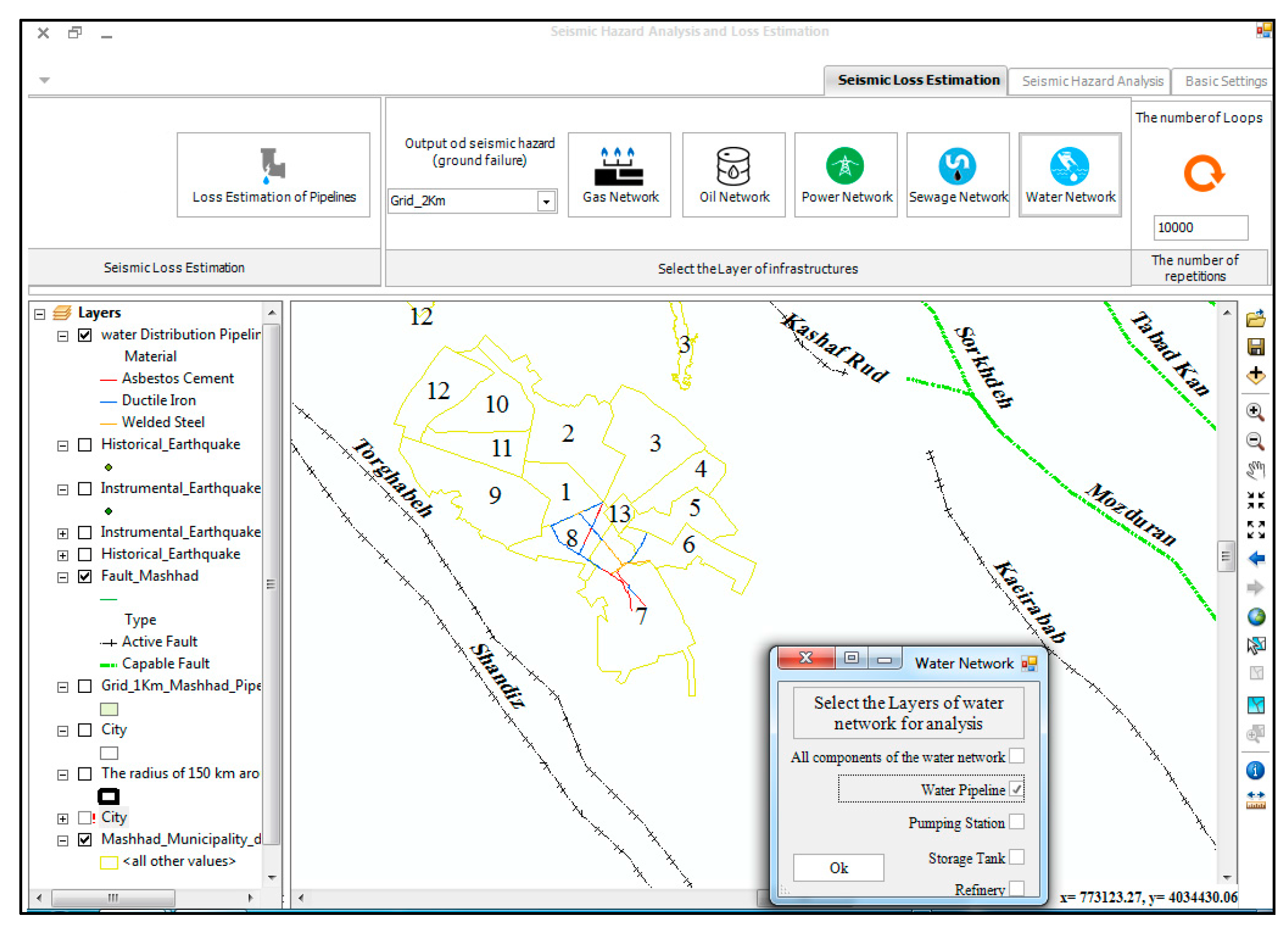
3.4. Seismic Damage Assessment of Pipelines

Damages to pipelines are either leak mode or break mode in each segment of the pipeline. In order to analyze the damage to network pipelines, the following steps should be taken:
  • First step: the output values’ extraction of seismic the damage assessment parameter (PGA, PGV, and PGD due to liquefaction or landslide) for each segment of pipelines.
  • Second step: calculation of the repair rate and failure probability for each segment of pipelines.
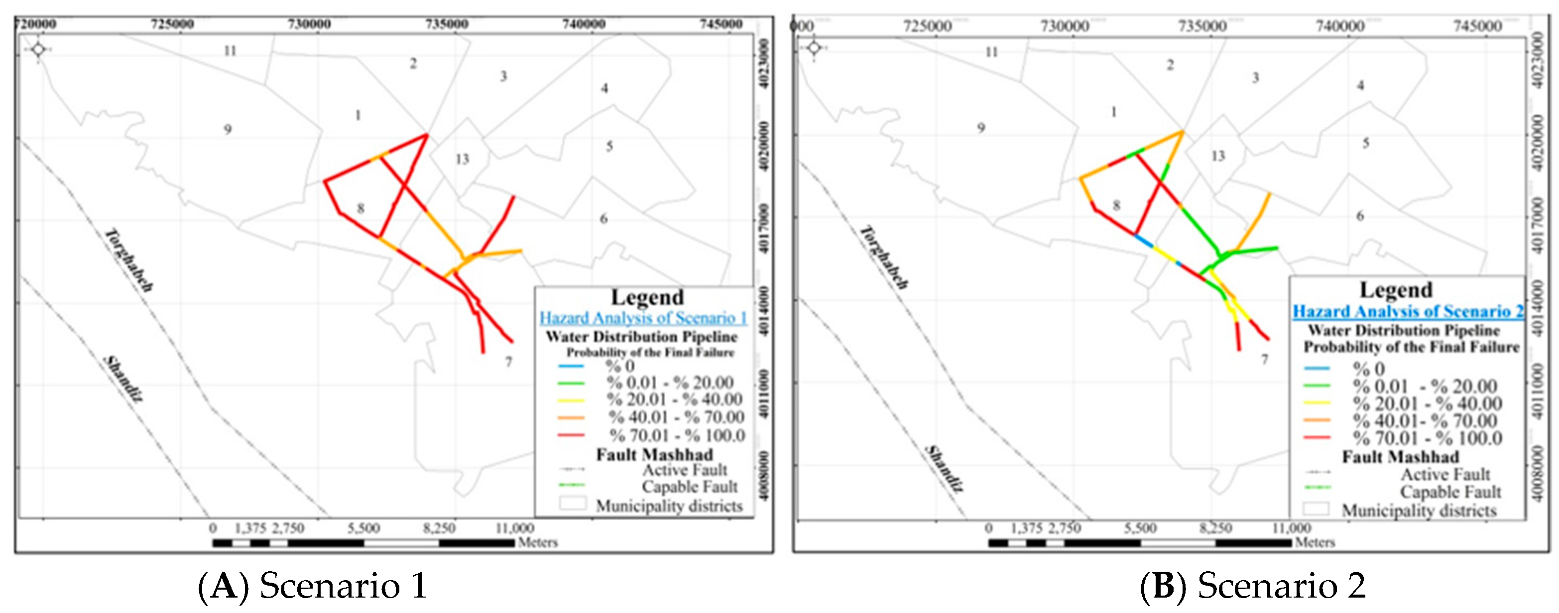
  • Third step: failure probability combination due to ground shaking or ground failure.
After determination of the failure probability due to ground shaking and ground failure for each segment, the failure total probability is combined based on union and intersection probability rules of 2 events as the following relationship:
P COMB = P G S + P GF ( P GS * P GF )
  • PCOMB: the final damage probability
  • PGF: failure probability due to ground shaking
  • PGS: failure probability due to ground failure
After determination of the total failure probability for each segment, the following operation is repeated:
  • First, a random value is chosen between zero and one. If the final damage probability for the segment is more than the selected random value, the segment fails and goes to the next step.
  • Each pipe segment for which its final damage probability is higher than the selected value has failed. Now, in this step, it should be determined that the segment breaks or leaks. Based on the studies of O’Rourke and Ayala [11], the hazard effect due to ground shaking (PGV) in pipelines occurs as 80% leak and 20% break, and the hazard effect due to ground failure and permanent displacements (PGD) in pipelines occurs as 80% break and 20% leak. Therefore, if we assume that the failure probability due to ground shaking is PGS and the failure probability due to ground failure is PGF, then:
  • If PGS > PGF, a random value is chosen between 0 and 100. If the chosen value for the pipe segment was between 0 and 80, the segment has leaked; otherwise, the segment has been broken.
  • If PGS < PGF, a random value is chosen between 0 and 100. If the chosen value for the pipe segment was between 0 and 80, the segment has been broken; otherwise, the segment has leaked.
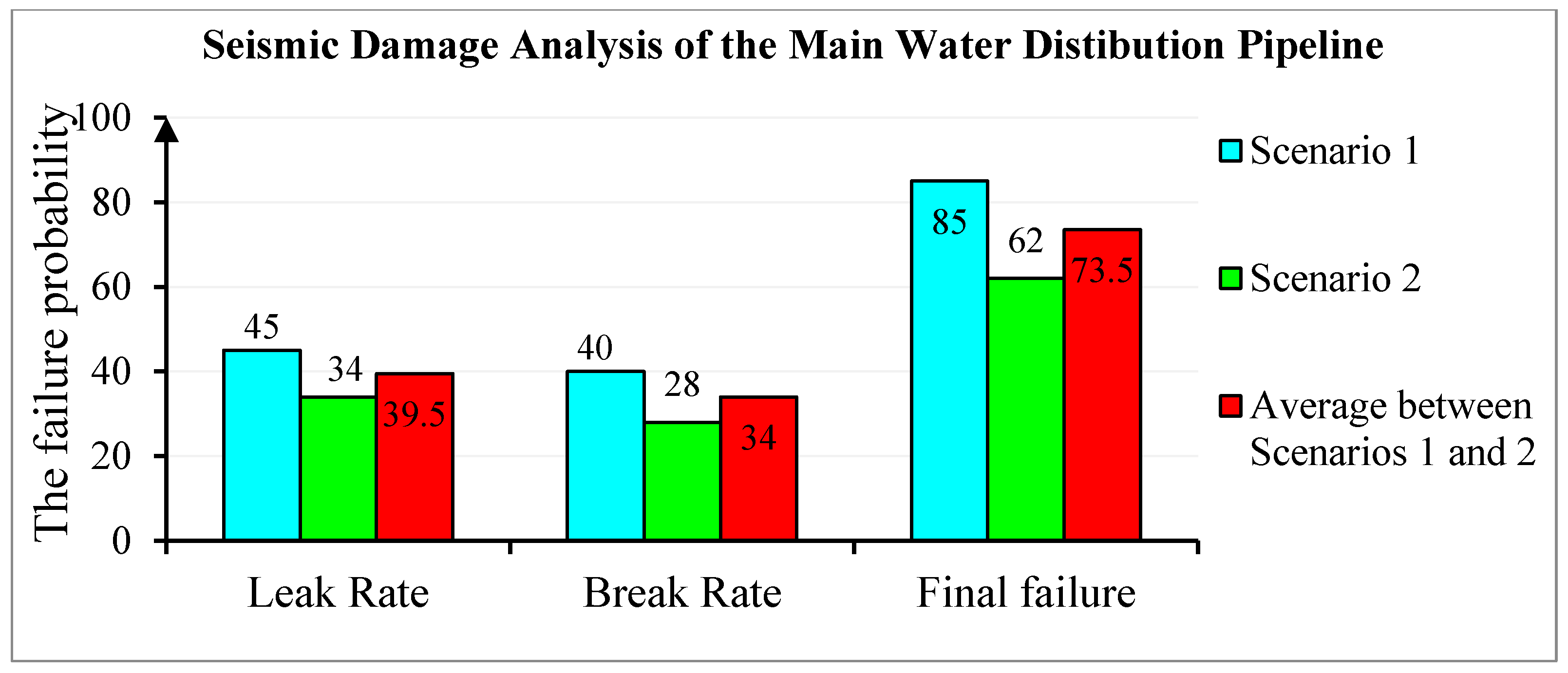
Therefore, in each earthquake scenario, the pipeline part that is subjected to break or leak can be determined. In this study, all operations are repeated ten thousand-times based on Monte Carlo simulation, and then, the achieved results for each pipeline segment are averaged. Finally, the numbers of leaks, breaks, leak rate, break rate and the final failure probability are determined for each pipeline segment based on ten thousand-times repetition. Based on the leak rate and break rate outputs for each segment, the damage states can be determined (Table 5).
All of these steps for all pipeline segments are repeated 10,000 times based on Monte Carlo simulation to consider the uncertainty of the system, as well (Figure 4). Monte Carlo methods are especially useful in modeling systems with many random variables with known probability distributions. Monte Carlo simulation, which is based on the iteration and generation of random variables from a specific range, is one of the most widely-used numerical methods [44].

4. Results

In this study, the seismic hazard analysis and the seismic damage analysis of water distribution pipelines are discussed. The desired analyses are performed for two scenarios of Table 3. As it is not possible to show all of the outcomes, the results of hazard analysis are not shown here, and only the city water distribution pipelines’ damage is presented. In the next step, the effects of various earthquake parameters on the pipelines, as well as the sensitivity of input parameters are evaluated.
The zoning map of the pipe leak rate and pipe break rate for Scenarios 1 and 2 is shown in Figure 5 and Figure 6, respectively. As can be seen in these figures, the amount of damage in Scenario 1 is more than the expected damage from Scenario 2. Moreover, it can be concluded that a segment cannot achieve a leak rate over 50% and a break rate over 50% simultaneously. The results obviously showed that the leak rate is higher than that of the break in various segments. However, the pipeline break rate is higher than the leak rate as the displacement due to liquefaction or landslide is greater than PGV, and the dominant hazard is the ground failure hazard regarding the high susceptibility of landslide or liquefaction.
The zoning map of pipeline damage probability based on Scenario 2 is shown in Figure 7. As can be seen in this figure, the pipeline damage probability in Scenario 1 is higher than Scenario 2, as the leak and break rates in Scenario 2 are less than Scenario 1. The damage in Scenario 2 also is less than Scenario 1 since the distance of earthquake location to the pipeline is not constant, and it varies in each analysis. This is the reason that the fault distance to the pipeline for Shandiz fault is less than the case we have for Scenario 2 as its location is selected randomly in a range of 50 km around the city.
The results of damage analysis for the main water distribution of Mashhad city are presented in the form of a chart in Figure 8. As can be seen from the figure, the leak percentage in Scenarios 1 and 2 is about 13% and 21% higher than the break percentage of pipelines, respectively. Therefore, it can be concluded that the break percentage is nearly equal to the leak percentage in the analyses, and this is due to moderate to high susceptibility of liquefaction in the area. On the other hand, the pipes’ break rate is very important for pipeline damage analysis because about 45% of pipelines’ damage is dependent on the pipes’ break rate.

5. Discussion

The main parameters and relationships that affect the pipeline damage analysis are discussed in this section.

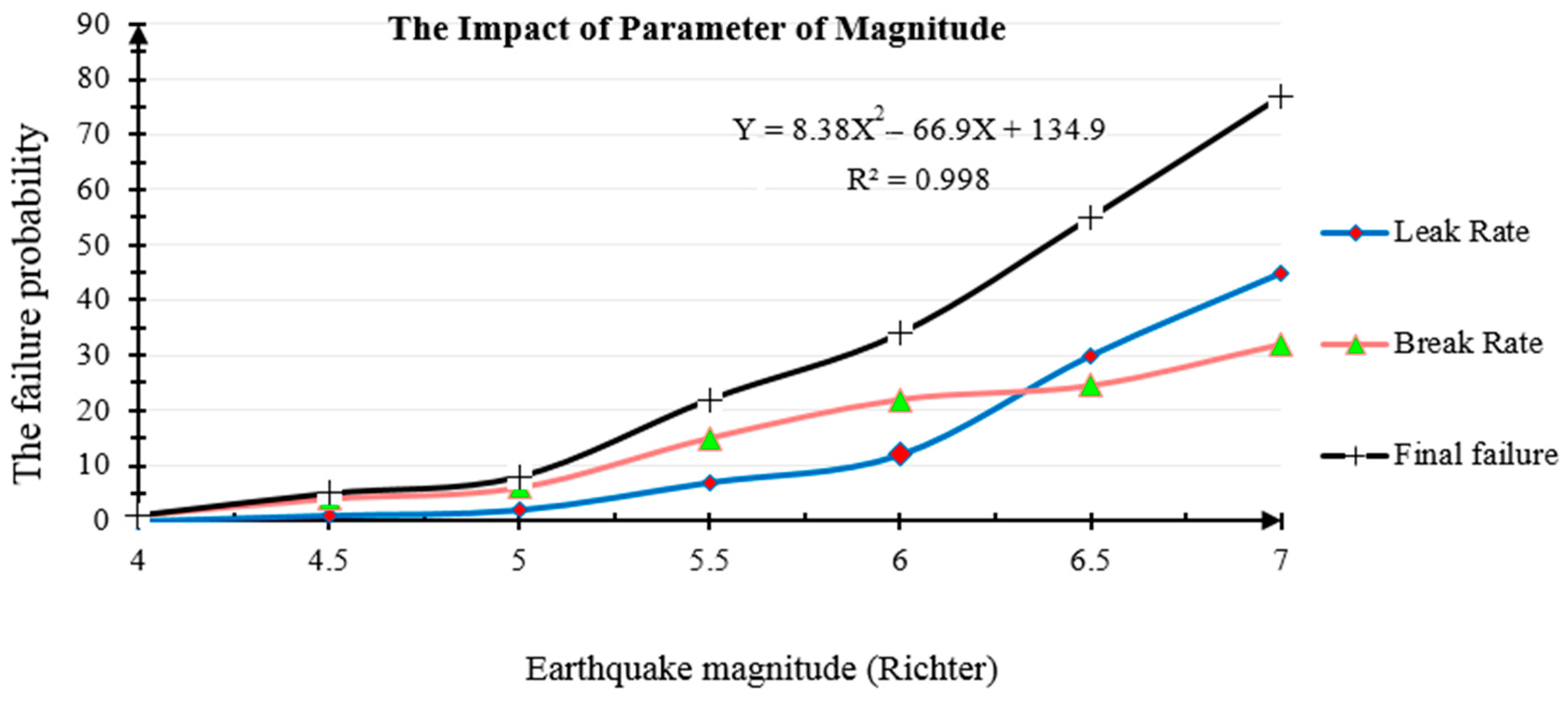
5.1. Determine the Effect of Earthquake Input Parameters

In this step, the effect of earthquake input parameters on the probability of damage to pipelines is determined. In other words, by changing the magnitude of leak percentage, the break percentage and the final failure, the probability of failure is measured (Figure 9). The probability of failure does not change too much for magnitudes less than 5 Richter, while in the range of 4 to 6 Richter, the break rate is higher than the leak rate. It is important to note that the failure probability of the leak rate increases and would be higher than the break rate for magnitudes more than 6.30. The reason is that the ground failure hazard is more dependent on ground conditions, and so, with the increasing magnitude, the ground condition is not changing. The ground shaking that effects the leak values is highly dependent on the earthquake input parameters; and by increasing magnitude, the PGV value becomes more than the PGD, and the repair rate becomes more than the break rate.
The leak percentage, the break percentage and the pipelines final damage probability are proportional to the change in focal depth, focal distance, PGV and PGD, respectively (Figure 10A to Figure 10D). Based on Figure 10A, if the focal depth is more than 50 km, the damage probability is very small. According to Figure 10B, the damage gradient at a focal distance less than 30 km is small, and the results are very similar to each other; while with the increasing distance, the gradient is increased. Figure 10C,D shows the changes in the output parameters of the seismic hazard analysis on the damage of the pipes. As it be seen in Figure 10C, the dominant damage is the leak percentage associated with the ground shaking hazard and the PGV; while in Figure 10D, the dominant damage is the break that is dependent on the ground failure hazard and the PGD. It should be noted that the pipeline damage probability is associated with the earthquake magnitude, focal depth, focal distance, PGV and PGD according to Figure 9 and Figure 10.

5.2. Sensitivity Analysis

The sensitivity analysis is performed to assess the dependency level of the developed model in this study on the input parameters including liquefaction susceptibility, landslide susceptibility, pipelines vulnerability and pipeline length.
Based on the sensitivity analysis, by changing the liquefaction susceptibility and landslide between three different states (without susceptibility, moderate susceptibility and high susceptibility) and calculating values for the leak percentage, the break percentage and the pipelines final damage probability, it can be concluded that the liquefaction susceptibility is able to effect the break rate and the final damage probability, while it does not change the leak rate. The reason is that the leak rate is dependent on the ground shaking hazard while changing the ground conditions, only increasing the ground failure hazard. Figure 11 also shows that the outputs of the model are not sensitive to landslide susceptibility as the hazard due to the landslide is not considered in the relationships used in this study for pipelines’ vulnerability.
Figure 12A shows the sensitivity analysis of the parameters of the vulnerability function and pipeline length in the damage probability analysis. This model uses the Federal Emergency Management Agency [6] relationship for which the anticipated damage value is higher than Eidinger [45] and ALA (American Lifeline Alliance) [13] relationships and is somewhat pessimistic. Based on Figure 12A, the final damage probability in the FEMA [6] relationship is greater than the other and in the ALA [13] relationship is less than the other. Furthermore, the break rate value of the Eidinger [45] and ALA [13] relationships has been estimated with greater values in comparison to the FEMA [6] relationship. It can be concluded that the failure probability based on the FEMA [6] relationship with respect to the Eidinger [45] and ALA [13] relationships has been estimated to be about 19% and 47%, respectively.
In seismic hazard analysis, in order to consider the distance effect and the geological parameters in each location, the pipelines are divided into a number of the same-sized segments. Then, for each segment, the output parameters are calculated. In this study, each segment length has been considered as 1000 m as the default in the analyses. Therefore, in order to determine what would be the effect of the change in length of segments on the outputs, three segments with a length of 100 m, 500 m and 5000 m are re-calculated. After comparing the results, it was observed that changing the pipeline length has a small impact on the probability of damage.

6. Conclusions

The past earthquakes experiences have shown that if the damage to lifelines leads to stopping public services after disasters’ occurrence, especially an earthquake in a city, the damages and injuries would be multiplied. Undoubtedly, the vulnerability analysis and investigation of pipelines after earthquakes can be effective in planning for disasters and for establishing an appropriate approach to prevent these events in major cities. In this study, a model is developed to perform numerous spatial analyses in the geospatial information system. The four main parts of the desired model include: the collecting data, seismic hazard analysis, vulnerability assessment and damages’ assessment of pipelines. The Monte Carlo simulation also is applied to consider uncertainties in damage analysis.
The results of this study briefly are:
  • Although the model presented in this paper was used for water pipelines as a case study, it can easily be evaluated for other pipelines just by having the vulnerability function in accordance with the relevant pipeline.
  • The experimental vulnerability assessment models are only able to estimate the leak and break values in the pipeline system due to an earthquake. Therefore, in order to solve this problem, few relationships are presented in the methodology for damage assessment by using the geospatial information system, which can specify the failure locations.
  • The relationships suggested in this model are capable of analyzing the damage of pipelines for two hazards (ground shaking and ground failure) due to earthquake simultaneously, unlike the similar studies in the literature. Some studies have not considered the ground failure hazard, while the high effect of this hazard was investigated in this study.
  • In addition, most of the studies are only based on the experimental relationships of pipelines’ vulnerability without considering the uncertainty in the results, while our model is considering the uncertainty based on Monte Carlo simulation. Hence, it is expected that the results are much closer to reality.
  • The results showed that the ductility of pipelines has significant effects on the amount of damages, while there would be higher damage probability for the segments with brittle materials than the flexible materials.
  • All three factors of magnitude, focal depth and focal distance have a great impact on the probability of damages for the pipeline system. For instance, when the magnitude exceeds 5 Richter, the probability of damage increases by 18%. In the case of focal depth less than 40 km, the probability of damage increases 15% by decreasing 10 km in the focal depth. On the other hand, decreasing the focal distance by 10 km will result in increasing the damage probability by about 6%.
  • The sensitivity analysis shows that the pipeline damage probability is sensitive to the liquefaction susceptibility, but is not sensitive to landslide susceptibility. The reason is that the failure due to landslide has not been considered in the vulnerability relationships of this model.
  • From the sensitivity analysis, it also can be concluded that the most pessimistic relationship is presented by FEMA (1999), because the damage probability in FEMA’s relationship is estimated as more than two other relationships.
  • Last, but not least, the sensitivity analysis showed that changing segments’ length has a small effect on outputs. It should be noted that the output results of all three, 100-m, 500-m and 5000-m segments, have converged to the output results of the 1000-m segment, which is one of the most important reasons for considering the 1000-m length by default for the pipelines’ damage assessment in this study.

Acknowledgments

The authors acknowledge the contribution of two anonymous reviewers, whose comments served to improve the overall quality of the paper. The authors would also like to thank Ali Alidoosti for the help and support during this research.

Author Contributions

Mohammad Eskandari has provided the majority of the research for this research and this paper. All authors have contributed to the design of the conceptual model. After designing the conceptual model, Mohammad Eskandari prepared the software for the seismic damage analysis with the programming language C#, which is an object-oriented programming language. It is important to note that this software that is used in this study uses two main libraries of ArcGIS Engine and NET Frameworks for reading and writing files and spatial processing on the data. Then, Mohammad Eskandari implemented and analyzed the data and wrote the paper. The supervisory teams are built of Babak Omidvar, Mahdi Modiri, Mohammad Ali Nekoie and Ali Asghar Alesheikh. Babak Omidvar provided the idea for this study, and he provides guidance into the direction of this work. Mahdi Modiri and Mohammad Ali Nekoie made important comments and suggestions on the manuscript. Ali Asghar Alesheikh has provided excellent technical advice in relation to programming and spatial analysis.

Conflicts of Interest

The authors declare no conflict of interest.

References

  1. Bhatia, S.C.; Kumar, M.R.; Gupta, H.K. A probabilistic seismic hazard map of India and adjoining regions. Ann. Geophysics 1999, 42, 1153–1164. [Google Scholar]
  2. Fallahi, A.; Zafari, H.; Bakhtiari, A. Urban areas and reduce the risk of injury. In The Fifth International Conference on Seismology and Earthquake Engineering; International Institute of Seismology and Earthquake Engineering: Tehran, Iran, 2007; pp. 92–99. (In Persian) [Google Scholar]
  3. Omidvar, B.; Eskandari, M.; Naeimi, M. Provide a model for the seismic damage Assessment to buried fuel pipelines in Kermanshah. J. Model. Eng. 2015, 13, 27–45. (In Persian) [Google Scholar]
  4. Eskandari, M.; Modiri, M.; Omidvar, B.; Alesheikh, A.A.; Nekooie, M.A.; Alidoosti, A. Providing model of seismic loss estimation of infrastructure by using spatial information systems. J. Geogr. Sci. 2016, 25, 91–111. (In Persian) [Google Scholar]
  5. Eskandari, M. Seismic Damage Estimation of Pipelines Buried Fuel—Case Study: Kermanshah City. Master’s Thesis, Tehran University, Tehran, Iran, 2011. (In Persian). [Google Scholar]
  6. Federal Emergency Management Agency. HAZUS MH 2.0 Earthquake Technical Manual; Department of Homeland Security: Washington, DC, USA, 2011.
  7. O’Rourke, M.; Deyoe, E. Seismic Damage to Segmented Buried Pipe. Earthq. Spectra 2004, 20, 1167–1183. [Google Scholar] [CrossRef]
  8. Katayama, T.; Kubo, K.; Sato, N. Earthquake Damage to Water and Gas Distribution Systems. In Proceedings of the National Conference on Earthquake Engineering, Earthquake Engineering Research Institute, Oakland, CA, USA, 18–20 June 1975; pp. 396–405. [Google Scholar]
  9. Barenberg, M.E. Correlation of pipeline damage with ground motions. J. Geotech. Eng. 1988, 114, 706–711. [Google Scholar] [CrossRef]
  10. Taylor, C.E. Technical Council on Lifeline Earthquake Engineering (TCLEE). Seismic Loss Estimates for a Hypothetical Water System: A Demonstration Project; American Society of Civil Engineers: New York, NY, USA, 1991; p. 181. [Google Scholar]
  11. O’Rourke, M.; Ayala, G. Pipeline damage due to wave propagation. J. Geotech. Eng. 1993, 119, 1490–1498. [Google Scholar] [CrossRef]
  12. O’Rourke, T.D.; Toprak, S.; Sano, Y. Factors affecting water supply damage caused by the Northridge earthquake. In Proceedings of the National Conference on Earthquake Engineering, Seattle, WA, USA, 31 May–4 June 1998; pp. 1–12. [Google Scholar]
  13. American Lifeline Alliance (ALA). Seismic Fragility Formulations for Water Systems; American Society of Civil Engineers (ASCE): Reston, VA, USA, 2001; p. 96. [Google Scholar]
  14. Pineda-Porras, O.; Ordaz-Schroeder, M. Seismic vulnerability function for high-diameter buried pipelines: Mexico City’s primary water system case. In Proceedings of the International Conference on Pipeline Engineering and Construction, Baltimore, MD, USA, 13–16 July 2003; pp. 1145–1154. [Google Scholar]
  15. Ayala, A.G.; O’Rourke, M.J. Effects of the 1985 Michoacan Earthquake on Water Systems and Other Buried Lifelines in Mexico; National Center for Earthquake Engineering Research: Buffalo, NY, USA, 1989. [Google Scholar]
  16. Tromans, I. Behaviour of Buried Water Supply Pipelines in Earthquake Zones. Ph.D. Thesis, University of London, London, UK, 2004. [Google Scholar]
  17. Rahnama, R.; Rasti, R.; Hassani, N.; Ghiasvand, M. Study of Seismic Vulnerability for Retrofitting Water Supply Network of Tehran District 11. J. Tehran Disaster Manag. Mitig. Organ. 2016, 5, 308–314. (In Persian) [Google Scholar]
  18. Berberian, M. Chapter 16—Patterns of Historical Earthquake Ruptures on the Iranian Plateau. In Developments in Earth Surface Processes; Manuel, B., Ed.; Elsevier: Amsterdam, The Netherlands, 2014; Volume 17, pp. 439–518. [Google Scholar]
  19. Gholami, Y.; Hayati, S.; Ghanbari, M.; Esmaili, A. Prediction of the Areas Vulnerable to Earthquake in Mashhad City. Sci. J. Manag. Syst. 2015, 3, 55–67. (In Persian) [Google Scholar]
  20. Berberian, M.; Yeats, R.S. Patterns of historical earthquake rupture in the Iranian Plateau. Bull. Seismol. Soc. Am. 1999, 89, 120–139. [Google Scholar]
  21. Falcon, N.L. A history of Persian earthquakes. Geogr. J. 1983, 149, 367–368. [Google Scholar] [CrossRef]
  22. Chang, S.E.; Shinozuka, M.; Moore, J.E. Probabilistic earthquake scenarios: Extending risk analysis methodologies to spatially distributed systems. Earthq. Spectra 2000, 16, 557–572. [Google Scholar] [CrossRef]
  23. Mirzaei, N.; Gheitanchi, M.; Naserieh, S.; Raeesi, M.; Zarifi, Z.; Tabaei, S.-G. Basic parameters of earthquakes in Iran. Danesh Negar. Publ. Tehran 2002, 37, 147–180. (In Persian) [Google Scholar]
  24. Wesnousky, S.G. Displacement and geometrical characteristics of earthquake surface ruptures: Issues and implications for seismic-hazard analysis and the process of earthquake rupture. Bull. Seismol. Soc. Am. 2008, 98, 1609–1632. [Google Scholar] [CrossRef]
  25. Strasser, F.O.; Arango, M.; Bommer, J.J. Scaling of the source dimensions of interface and intraslab subduction-zone earthquakes with moment magnitude. Seismol. Res. Lett. 2010, 81, 941–950. [Google Scholar] [CrossRef]
  26. Blaser, L.; Krüger, F.; Ohrnberger, M.; Scherbaum, F. Scaling relations of earthquake source parameter estimates with special focus on subduction environment. Bull. Seismol. Soc. Am. 2010, 100, 2914–2926. [Google Scholar] [CrossRef]
  27. Wells, D.L.; Coppersmith, K.J. New empirical relationships among magnitude, rupture length, rupture width, rupture area, and surface displacement. Bull. Seismol. Soc. Am. 1994, 84, 974–1002. [Google Scholar]
  28. Nowroozi, A.A. Empirical relations between magnitudes and fault parameters for earthquakes in Iran. Bull. Seismol. Soc. Am. 1985, 75, 1327–1338. [Google Scholar]
  29. Zare, M.; Bard, P.Y.; Ghafory-Ashtiany, M. Site characterizations for the Iranian strong motion network. Soil Dyn. Earthq. Eng. 1999, 18, 101–123. [Google Scholar] [CrossRef]
  30. Ghodrati, G.A.; Mahdavian, A.; Dana, F.M. Attenuation Relationships for Iran. J. Earthq. Eng. 2007, 11, 469–492. [Google Scholar]
  31. Campbell, K.W.; Bozorgnia, Y. NGA Ground Motion Model for the Geometric Mean Horizontal Component of PGA, PGV, PGD and 5% Damped Linear Elastic Response Spectra for Periods Ranging from 0.01 to 10 s. Earthq. Spectra 2008, 24, 139–171. [Google Scholar] [CrossRef]
  32. Youd, T.L.; Perkins, D.M. Mapping liquefaction-induced ground failure potential. J.Soil Mech. Found. Div. 1978, 104, 433–446. [Google Scholar]
  33. Seed, H.B.; Tokimatsu, K.; Harder, L.; Chung, R.M. Influence of SPT procedures in soil liquefaction resistance evaluations. J. Geotech. Eng. 1985, 111, 1425–1445. [Google Scholar] [CrossRef]
  34. National Research Council. Liquefaction of Soils during Earthquakes; The National Academies Press: Washington, DC, USA, 1985; p. 255. [Google Scholar]
  35. Liao, S.S.; Veneziano, D.; Whitman, R.V. Regression models for evaluating liquefaction probability. J. Geotech. Eng. 1988, 114, 389–411. [Google Scholar] [CrossRef]
  36. Eskandari, M.; Omidvar, B.; Modiri, M.; Nekoie, M.A.; Al-Sheikh, A.A. Model of seismic damage analysis of critical infrastructure based on Geographic Information System. J. Emerg. Manag. 2017. in press (In Persian) [Google Scholar]
  37. Keefer, D.K.; Wilson, R. Predicting earthquake-induced landslides, with emphasis on arid and semi-arid environments. Landslides Semi-arid Environ. 1989, 2, 118–149. [Google Scholar]
  38. Wieczorek, G.F.; Brown, W.M.; Mark, R.K.; Rice, P.; Alger, C.S. La Honda Landslide Test Area, San Mateo County, California. In Landslides in Central California: San Francisco and Central California, July 20–29, 1989; American Geophysical Union: Washington, DC, USA, 2013; pp. 38–43. [Google Scholar]
  39. Makdisi, F.I.; Seed, H.B. Simplified Procedure for Estimating Dam and Embankment Earthquake-Induced Deformations; ASAE Publication No. 4-77; ASAE: Washington, DC, USA, 1977. [Google Scholar]
  40. LessLoss. Prediction of Ground Motion and Loss Scenarios for Selected Infrastructues Systems in European Urban Environments; Risk Mitigation for Earthquakes and Landslides; Faccioli, E., Ed.; Copernicus: Vincennes, France, 2007; p. 210. [Google Scholar]
  41. Honegger, D.; Eguchi, R. Determination of the Relative Vulnerabilities to Seismic Damage for Dan Diego Country Water Authority (SDCWA) Water Transmission Pipelines; Springer: Barcelona, Spain, 1992. [Google Scholar]
  42. O’Rourke, T.D.; Jeon, S. Factors affecting the earthquake damage of water distribution systems, Optimizing Post-Earthquake Lifeline System Reliability. In Proceedings of the 5th U.S. Conference on Lifeline Earthquake Engineering, Seattle, WA, USA, 12–14 August 1999; pp. 379–388. [Google Scholar]
  43. Mouroux, P.; Le Brun, B. Risk-Ue Project: An Advanced Approach to Earthquake Risk Scenarios With Application to Different European Towns. In Assessing and Managing Earthquake Risk: Geo-scientific and Engineering Knowledge for Earthquake Risk Mitigation: Developments, Tools, Techniques; Oliveira, C.S., Roca, A., Goula, X., Eds.; Springer: Dordrecht, The Netherlands, 2006; pp. 479–508. [Google Scholar]
  44. Goodarzi, E.; Teang Shui, L.; Ziaei, M. Dam overtopping risk using probabilistic concepts – Case study: The Meijaran Dam, Iran. Ain Shams Eng. J. 2013, 4, 185–197. [Google Scholar] [CrossRef]
  45. Eidinger, J. Seismic Fragility Formulations for Water Systems; American Lifelines Alliance, G&E Engineering Systems Inc.: Oakland, CA, USA, 2001; p. 96. [Google Scholar]
Figure 1. The conceptual model for seismic damage assessment of pipelines using geospatial analysis.
Ijgi 06 00169 g001
Figure 2. Map of faults and water distribution pipelines.
Ijgi 06 00169 g002
Figure 3. Geology map.
Ijgi 06 00169 g003
Figure 4. Developed computer program for the seismic damage analysis of pipelines.
Ijgi 06 00169 g004
Figure 5. Zoning map of the leak rate in two probable scenarios.
Ijgi 06 00169 g005
Figure 6. Zoning map of the break rate in two probable scenarios.
Ijgi 06 00169 g006
Figure 7. Zoning map of the damage probability in two probable scenarios.
Ijgi 06 00169 g007
Figure 8. Summary of the damage results of water distribution pipelines in different scenarios.
Ijgi 06 00169 g008
Figure 9. Determine the impact of magnitude on the failure probability of pipelines.
Ijgi 06 00169 g009
Figure 10. The impact of various earthquake parameters on the failure probability of pipelines.
Ijgi 06 00169 g010
Figure 11. The sensitivity analysis of the parameters of the liquefaction and landslide susceptibility in the failure probability of pipelines.
Ijgi 06 00169 g011
Figure 12. The sensitivity analysis of the parameters of the vulnerability function and the pipeline length in the failure probability of pipelines.
Ijgi 06 00169 g012
Table 1. The comparison of the various vulnerability functions of pipelines [16]. ALA, American Lifeline Alliance; PGA, Peak Ground Acceleration; PGV, Peak Ground Velocity; MMI, Modified Mercalli Intensity; PGD, Permanent Ground Displacement.
Event IDDateEarthquake NameCountryMagnitudeVarious Vulnerability Functions
Katayama et al. (1975)Isoyama and Katayama (1982)Eguchi (1983)Barenberg (1988)Ballantyne et al.(1990)Eguchi (1991)ASCE/TCLEE (1991)O’Rourke et al. (1991)Hamada (1991)Tiedemann (1992)O’Rourke and Ayala (1993) (HAZUS)Eidinger (1995, 1998)Kitaura and Miyajima (1996)Hwang and Lin (1997)O’Rourke et al. (1998)Isoyama et al. (2000)ALA (2001)
Earthquake data used
118-Apr-1906San FranciscoU.S.7.2
201-Sep-1923KantoJapan7.9
311-Mar-1933Long BeachU.S.6.5
428-Jun-1948FukuiJapan7.1
513-Apr-1949S Puget SoundU.S.6.7
616-Jun-1964NiigataJapan7.5
729-Apr-1965Puget SoundU.S.6.5
816-May-1968Tokachi-okiJapan7.9
901-Oct-1969Santa RosaU.S.5.6
1009-Feb-1971San FernandoU.S.6.6
1123-Dec-1972ManaguaNicaragua6.3
1228-Jul-1976TangshanChina7.6
1312-Jun-1978Miyagiken-okiJapan7.4
1415-Oct-1979Imperial ValleyU.S.6.5
1502-May-1983CoalingaU.S.6.4
1626-May-1983Nihonkai-chubuJapan7.7
1719-Sep-1985MichoacanMexico8
1801-Oct-1987WhittierU.S.5.9
1925-Apr-1989TlahuacMexico6.9
2018-Oct-1989Loma PrietaU.S.7
2128-Dec-1994Sanriku HarukaJapan7.7
2217-Jan-1994NorthridgeU.S.6.7
2316-Jan-1995Hyogoken-nanbuJapan6.9
The Number of Earthquakes
6143647835676134112
Strong-Motion Parameters
PGAPGAMMIPGVMMIMMIPGAMMIPGAPGAPGVPGVPGAPGAMMI
PGA
PGV
PGD
PGA
PGV
PGV
Table 2. Determine the maximum magnitude earthquake due to activating the Shandiz fault based on different relationships.
NameEquationFault TypeThe Moment Magnitude (Richter)Average of the Moment Magnitude (Richter)
Wesnousky [24] Mw * * = 5.56 + 0.87   log L * Strike-slip7.2387.334
Mw = 6.1 + 0.47   log L Normal-
Mw = 4.11 + 1.88   log L Reverse-
Mw = 5.30 + 1.02   log L All-
Strasser et al. [25] Mw = 4.87 + 1.39   log L All7.553
Blaser et al. [26] Mw = 4.13 + 1.61   log L Strike-slip7.236
Mw = 4.53 + 1.61   log L Reverse-
Mw = 3.83 + 1.85   log L All-
Wells and Coppersmith [27] Mw = 5.16 + 1.12   log L Strike-slip7.320
Mw = 4.86 + 1.32   log L Normal-
Mw = 5.00 + 1.22   log L Reverse-
Mw = 5.08 + 1.16   log L All-
Nowroozi [28] Mw = 1.26 + 1.24   log L All L *7.323
* L: fault failure length in all relationships in kilometers (except Nowroozi’s relationship in meters); ** Mw: earthquake moment magnitude.
Table 3. Summary of the two earthquake scenario parameters.
ScenarioScenario NameFocal Depth (km)Magnitude (Richter)Earthquake Location (X, Y)
1Shandiz fault207.334Randomly in every time of analysis, a position of the Shandiz fault is selected.
2Random selectionBetween 3 and 25 kmBetween 6 and 7.5 RichterRandomly in every time of analysis, a position is selected within the radius of 50 km from the city.
Table 4. Damage functions for water pipelines [6]. CI, Cast Iron; AC, Asbestos Cement; DI, Ductile Iron.
Damage Caused by PGV (cm/s)Damage Caused by PGD (Inch)
R.R. ≅ 0.0001 × PGV 2.25R.R. ≅ Prob [Liq] × PGD 0.56
Pipe TypeMultiplierExample of PipeMultiplierExample of Pipe
Brittle Pipes1CI, AC, RCC1CI, AC, RCC
Ductile Pipes0.3DI, S, PVC0.3DI, S, PVC
Table 5. Classification of damage levels for water pipelines.
Criteria of Damage Levels of Water Pipelines
Based on the Rate of Leak [43]Based on the Rate of Break [41]
The Rate of LeakDamage StateThe Rate of BreakDamage State
Less than 0.05Low0None
Between 0.05 and 0.15Moderate0.6Slight
Between 0.15 and 0.60Extensive2Low
More than 0.60Complete14Moderate
38Severe
75Extensive
100Complete

