A Full Level-of-Detail Specification for 3D Building Models Combining Indoor and Outdoor Scenes


1
School of Resource and Environmental Sciences, Wuhan University, 129 Luoyu Rd., Wuhan 430079, China
2
Collaborative Innovation Center of Geospatial Technology, Wuhan University, 129 Luoyu Rd., Wuhan 430079, China
3
The Key Laboratory for Geographical Information Systems, Ministry of Education, Wuhan 430079, China
4
Wuhan Land Use and Urban Spatial Planning Research Center, 55 Sanyang Rd., Wuhan 430014, China
*
Authors to whom correspondence should be addressed.
ISPRS Int. J. Geo-Inf. 2018, 7(11), 419; https://0-doi-org.brum.beds.ac.uk/10.3390/ijgi7110419
Submission received: 11 September 2018
/
Revised: 1 October 2018
/
Accepted: 27 October 2018
/
Published: 30 October 2018
Abstract
:The level of detail (LoD) concept in CityGML (City Geography Markup Language), which indicates how closely the model mirrors its real-world counterpart, has been accepted and applied widely in various applications, including the 3D modeling of buildings. However, with an increasing number of human activities occurring in the indoor environment, the standardized LoD definition appears to be insufficient because of its narrow classifications for interior features, which can be presented only in LoD4. In view of this drawback, an extended indoor LoD (ILoD) specification is proposed, particularly for indoor spaces, allowing the existing LoD to become a more precise outdoor LoD (OLoD) by exploiting the advantages of two other international standards: Industry foundation classes (IFC) and IndoorGML. In this paper, the interior space is divided into distinct systems of three semantic aspects (structure, connectivity, and volume); the approach can be considered the guiding ideology to define the detailed indoor levels following a concrete theoretical realization based on extending the UML diagram of CityGML’s building model. Moreover, a continuous and seamless full LoD (FLoD) set obtained by combining various OLoDs and ILoDs is subsequently listed to realize the full specification for 3D building models. Furthermore, to demonstrate the proposed specification and prove the applicability of the building model at different LoDs, a practical experiment is conducted.
1. Introduction
Since the first geographic information system (GIS) was developed in the 1960s [1], such systems have been widely adopted and popularized in numerous fields, such as heritage preservation, location selection, land management, energy monitoring, and traffic navigation [2,3,4,5,6,7]. Therein, GIS application to 3D city modeling has always been a hot research topic during the past decade [8,9,10,11]. However, the research studies have typically focused on outdoor modeling, with the rapid development of computer-network and mobile-telephone technologies, indoor modeling has rapidly gained more interests from researchers and developers worldwide. Indeed, the U.S. Environmental Protection Agency, whose mission is to protect human health and the environment, has reported that 75% of the world’s people live in cities, with nearly 90% of their time spent in building interiors [12].
Different outdoor application scenarios have a range of different requirements and therefore require appropriate representations of buildings; this situation is also equally applicable in indoor situations [13,14]. Therefore, certain common technologies and concepts of outdoor modeling can be used for the interior, e.g., the level of detail (LoD), which can be traced back to October 1976, when James H. Clark first applied it to a 3D computer graphic [15]. While introduced into the 3D city modeling field, differences arise regarding not only the structure complexity, richness of detail, and amount of data, but also the semantic and topological aspects of the city objects, for addressing more application issues [16]. Geospatial models generally face inherent complexity and diversity; therefore, a systematic and scientific classification methodology is required and must be specified for corresponding modeling schemas and formats [17].
CityGML is an open geospatial consortium (OGC) encoding standard that was released as version 1.0 in 2008 [18] and as version 2.0 in March 2012 [19]. Five successively refined LoDs, LoD0 to LoD4, are currently distinguished for building models of various geometrical and semantic degrees of accuracy [20]. The coarsest level, LoD0, is essentially a 2.5D representation in which buildings are represented by footprint or roof-edge polygons. LoD1 is generalized as well-known prismatic blocks with vertical walls and flat roofs. In LoD2, the building model has thematically differentiated boundary surfaces and various roof structures, along with additional installations, such as balconies and dormers. Finally, LoD3 denotes the most detailed architectural exterior shell, potentially including openings (doors and windows). Interior structures, such as rooms, furniture, or installations, are appended into LoD4 with the same outer appearances as those of the LoD3 models.
The current LoD definition in CityGML 2.0 has been accepted and applied by stakeholders in both academia and industry for its ease of use and exchange. However, due to the rising variety of applications, the current LoD categorization appears to be insufficient; the major drawback is that this categorization assigns all interior features to only one level, LoD4, which simultaneously requires an elaborate external representation. This approach cannot accommodate increasingly complex indoor applications, which may require interior structures of varying accuracy levels, rather than a packaged whole. When focusing on the indoor environment, the exterior details perhaps become insignificant for they may have little influence on certain analysis results. Hence, an appropriate definition of different complexity levels for indoor data specification, usage, and exchange is urgently required.
In this study, we propose an improved full LoD specification for building models combining indoor and outdoor scenes to meet the requirements of various applications. To achieve this goal, we first strip the LoD4 from the original LoD definition in CityGML and propose an indoor LoD concept for the interiors of 3D building models based on the application domain extension (ADE) mechanism [19]. Then, the connection between indoor and outdoor scenes within the different LoD models is further investigated. To support this research, several relevant advanced ideas are introduced, including two additional international standards, namely, industry foundation classes (IFC) and IndoorGML, and the design concept of the modern architectural interior space. To validate the proposed specification and prove the applicability of the building model at different LoDs, a practical experiment on a building model is also conducted. The remainder of this paper is organized as follows. Section 2 provides our research methodology consisting of the research motivation, the related standards and researches, the design idea, as well as the research route. Section 3 discusses the concrete definition and realization of the indoor LoD division based on the CityGML ADE mechanism. Next, in Section 4, the full LoD specification integrating different indoor and outdoor features in geometry and semantics is suggested. Section 5 illustrates a practical experimental demonstration of a five-story building model. Finally, conclusions and plans for future studies are provided in Section 6.
2. Research Methodology
2.1. Research Background
The current LoD concept of CityGML is no longer sufficiently flexible for the emergence of indoor applications of 3D city models, and multiple attempts have been made to address the issue. Hagedorn et al. proposed four relevant indoor LoDs that are different in their thematic, geometric, topological and visual complexity, and their indoor LoD building model consisted of three components: A thematic model, a geometry model, and a routing model [21]. Isikdag and Zlatanova presented a new building information modeling (BIM)-oriented modeling methodology resulting in the definition of a novel BIM-based model (BO-IDM) dedicated to facilitating indoor navigation [22]. Boeters et al. defined a level of detail LoD2+ by extending the comparably complex indoor building geometries of the CityGML LoD2 specification to the exterior building geometries [23]. A formal and consistent framework was provided by Biljecki et al. to define a discrete and continuous LoD by determining six metrics that constitute this LoD and discussing their quantification and relationships; a series of 10 discrete LoDs, LoD0 to LoD9, implementing the framework were derived as an example [24]. Löwner et al. proposed two new LoD concepts of geometrical level of detail (GLoD) and semantic level of detail (SLoD) that allow a building to be partitioned into an exterior and an interior, each with one or more explicit LoDs of geometrical and semantic aspects [25]. A multi-representation concept (MRC) that enables a user-defined definition of LoDs was presented by Löwner and Gröger for the further definition of the LoD concept [26]. In addition, to evaluate the LoD concepts that were recently proposed in the field of semantic 3D city models, Löwner et al. developed six evaluation criteria that may be highly valuable for defining the profiles of the new LoD concept in CityGML 3.0 [27].
Previous research studies have more or less improved the deficiencies of the current LoD division of building models. In fact, there have been more researches about the indoor LoD specification, no matter from the geometric, semantic or topological aspects; the common weakness could be summed up into the following two points. First, the specialized research emphasis placed on the indoor perspective is to some extent insufficient or not systematic enough. The obvious drawback lies in the neglect of the interior furniture, which would play extremely important role in indoor scene, and the processing method of the furniture model is a research issue for reducing the complexity so as to provide a better display effect. Besides, the inside and outside of a building have never been independent existences in real life, so is the building model in computers virtual word. So the exploration about how to systematically combine the indoor and outdoor scenes seamlessly from LoD perspective is another important point needs to be disposed in this study. An example investigated herein concerns the indoor environment of a supermarket, which is often characterized by a larger flow of people. Information regarding the shelf height and location, which is commonly neglected, is equally important and deserving of further attention, for the shelf layout influences not only the distribution of goods, but also the customer line of sight. Customers often forget their location and surroundings when they become immersed within a supermarket setting, especially those that are particularly large or unfamiliar. It is therefore very dangerous for these customers when an emergency occurs, especially if clear guidance towards the exit is not available. Thus, 3D simulations of such layouts are becoming increasingly popular and indispensable, and how to arrange the location and adjust the height and location of the shelves scientifically is fundamental to the simulation; accordingly, the block model presented in Figure 1 may constitute a good solution, due to its simplicity and interpretability.
2.2. Related Standards and Researches
As indoor applications gain popularity, a corresponding model of indoor spatial data becomes increasingly necessary and important among the various commercial software packages or commonweal organizations. In addition to CityGML, several other standards of indoor space have been published, of which industry foundation classes (IFC) and IndoorGML are the most widely accepted.
IFC is a standardized open data model developed by the international organization buildingSMART for BIM information that is exchanged and shared among the various participants in a building-construction or facility-management project to manage complex communication throughout the building life cycle [28]. Therefore, the architectural features defined in the IFC model are relatively complete and include more detailed classes for interior facilities than the CityGML building model. Despite the semantic similarities of CityGML and IFC, the geometry-modeling paradigms are different because of the different points of concern; the building model in the GIS domain is represented by its enclosed observable surfaces, whereas the BIM domain is typically composed of volumetric and parametric primitives. To break the “information isolated island” and promote information exchange, multiple studies in the literatures [29,30,31,32] have been performed in recent years, generally focusing on the conversion or integration between the two standards. Additionally, commercial software products for conversion from IFC to CityGML, such as IfcExplorer and FME (Feature Manipulate Engine), have also contributed to the development of 3D city modeling integration. In this study, we introduce selected indispensable concepts defined in IFC for indoor features, such as a beam, column, stair, and ramp, to fulfill the definition of interior structures of the CityGML building model. Note that there is also a LoD, Level of Development, concept in BIM—which is the reference for AEC practitioners to specify and articulate with a high level of clarity the content and reliability of building information models at various stages in the design and construction process [33]. Although the two concepts have the same abbreviation, they are substantially different. Level of Detail is essentially how much detail is included in the model element, while Level of Development is the degree to which the element’s geometry and attached information has been thought through. In other words, Level of Detail could be considered as an input to the element, while Level of Development is a reliable output.
IndoorGML is another OGC standard that provides additional encoding features for indoor spatial information and covers the necessary requirements of indoor applications, such as indoor navigation [34]. While CityGML emphasizes the feature types of building components, such as the roof, ceiling, floor, and wall, the main focus of IndoorGML is to provide classes that describe the primary connectivity relationships in addition to a multi-layered model for the indoor spaces and a data model dedicated to navigation [35]. The space in IndoorGML corresponds to the room defined in CityGML when it is empty. This case represents satisfactory matching between CityGML and IndoorGML, because IndoorGML is not associated with architectural components themselves, but is bounded by the form of the space cells (e.g., rooms and corridors), where objects can be located and navigated [36,37,38]. However, the assumption that space cells are empty is not realistic because the furnishing elements inside the building cannot be ignored [35]. Thus, we discuss a new paradigm that supports indoor navigation in a full 3D model with the restrictions of the furniture (e.g., table and bed) and installations (e.g., columns and stairs); the working state (e.g., open and closed) of the transportation facilities is considered simultaneously as well.
2.3. Design Idea of Architectural Interior Space
Generally, the concept of “building” is used to refer to the exterior shell of the interior space, which can be further viewed as the container of the indoor features. A perfectly complete building model depends on a realistic appearance and has a suitable interior design. Since the level of exterior detail of the building model has already been delicately defined in CityGML 2.0, this section emphasizes the analysis of its interior scenarios. Here, combing with the design concept of the interior space in the architecture field [39,40,41,42,43,44,45], we perform a systematic analysis from a semantic perspective that divides the space into three aspects: Structure, connectivity, and volume.
2.3.1. Structure System
As summarized in the IndoorGML standard, the applications of indoor spatial information can be classified into two categories: The management of building components and indoor facilities and the use of indoor space [34]. While the goal of IndoorGML is the usage and localization of (stationary or mobile) features in indoor space, the geometric representation of the architectural components that define the spaces is still the firm precondition of indoor modeling.
The architectural components within the building are extremely rich, both in geometry and semantics. In this topic, we concentrate on the components that can enclose the indoor space. Several elements (including roof, wall, ground, ceiling, floor, door, window and room) are already defined in the CityGML standard; however, two indispensable features used to represent the load-bearing components of the structure, namely, column and beam, should be considered in the indoor modeling. For example, ancient Chinese architecture is characterized by the use of a timber framework, with wooden pillars and beams bearing nearly all the weight of the entire structures and walls and windows used only to separate rooms [46]. Moreover, beams and columns may appear as obstacles in a passageway, corridor, or basement because they narrow or shorten the activity space; this aspect is particularly important in certain emergencies (e.g., a fire disaster) [23].
Additionally, another vital concept, namely, the story, should be proposed for today’s increasingly common high-rise buildings, although these buildings might present a uniform external façade. CityGML currently does not provide a specific concept for the representation of a story; rather, this representation is obtained implicitly via the notion of CityObjectGroups located at a certain height level. In IFC, the structure is smoothly organized by breaking down a building into stories and then into spaces that form a specific story. In this structural system, we suggest that the similar concept of the story in the IFC standard should be adopted explicitly in more indoor applications. In other words, when representing the newly proposed features, the building model should consist of an explicit definition of stories (at least one), with each building story having zero or more spaces related to it.
2.3.2. Connectivity System
Among varieties of 3D indoor academic explorations, route navigation is always a research emphasis and is also the foundation for other further applications, such as emergency response or robot walking. Such navigation is also precisely the motivation and purpose for defining the IndoorGML standard [34]. The basic categories of connectivity modes in route navigation can be derived in two directions: Horizontal and vertical.
Horizontal connectivity can be transformed into navigation in a 2D perspective, based on a floor plan, projection, or other 2D representations of buildings, and has obtained considerable favorable achievements over the years [46,47,48,49]. Analyzing the relevant literature, we find that some common points are that the major research objectives are the discovery of the locations of doors and windows that have been defined in CityGML inheriting the abstract feature _Opening. In IndoorGML, the door and window and the room are classified into navigable cells, and transportation between them is represented as the determination of the connectivity between the cells. However, the size, state and direction of opening of doors and windows have not yet been mentioned in the standards; these aspects are actually also important because they directly influence accessibility when planning a navigation route.
Vertical connectivity appears when the application requirements span multi-story buildings in true 3D scenarios. Different stories can be linked by several connected features, such as a stair, ramp, or elevator (escalator). A stair, sometimes accompanied by a ramp, can be used to represent the connection of two adjacent floors, and an elevator (escalator) can be used to connect two or more floors. Similarly, relevant attributes regarding the traffic capacity should be attached, such as the state of the stair (which might be blocked), and the capacity of the elevator is based on its type (e.g., passenger or luggage elevator).
2.3.3. Volume System
Space in the model is a virtual (non-existing) element used to represent a closed volume, such as a room or a corridor. Although the space concept has been defined in IFC and IndoorGML, these definitions are different in a concrete interpretation; for example, in IFC, the feature IfcSpace is an area or volume in a building that may span several connected spaces or even other spaces. In IndoorGML, a space is a closed-volume cell bounded by building elements and used for living or work; therefore, the space can be used for navigation. The latter representation paradigm is similar to the Room class in CityGML; accordingly, a Corridor class is extended for a more complete interior space division.
These standards focus on spaces available for navigation in the indoor environment. However, the spaces are idealized as empty boxes at a simplified level with static indoor features (such as furniture or other installations) that typically occupy the spaces being neglected [35]. In fact, indoor features play important roles in certain applications inside buildings, because these features may serve as shelters or obstacles, which should be regarded as constraints when designing routes for indoor navigation. Thus, excluding the space occupied by the features is essential and amounts to extracting the actual free navigable subspace in such a model [23].
Furniture in the CityGML standard is expressed as the BuildingFurniture class whose geometry may be represented by an explicit geometry or by an implicit geometry object called the implicitGeometry class, in which the geometry of a prototype building furniture is stored only once in a local coordinate system and referenced by other building furniture features. The furniture in the IFC standard is described by the IfcFurnishingElement class, which can be independently simple objects with relatively simple geometries or be complex objects composed of several components with complex geometries. Although the two complex representations are vivid in the context of realistic visualization, high-performance hardware is required, and the presentation effect becomes unsatisfactory when the scene becomes more complex. Therefore, a simplification of the furnishing elements to simple shapes is required to reduce the complexity for space extraction.
2.4. Research Route
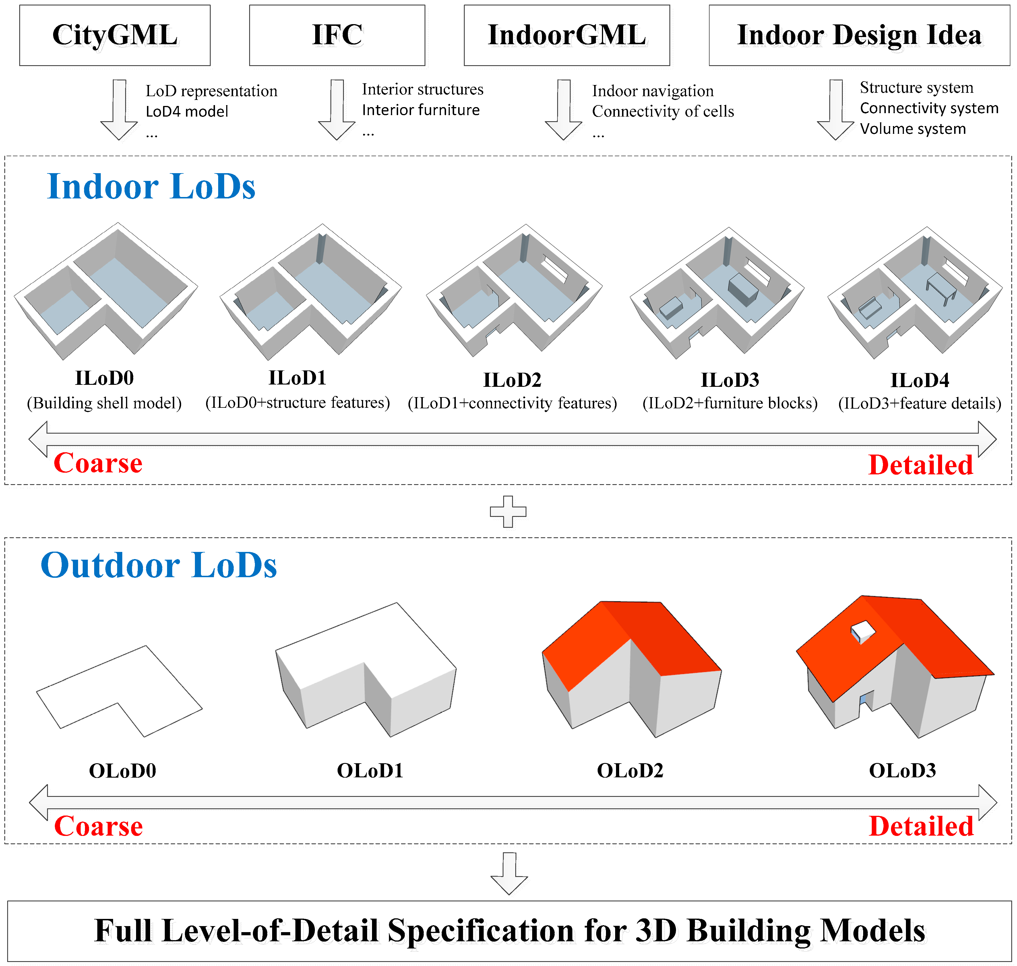
In order to achieve a continuous and seamless full level-of-detail specification for 3D building models, the indoor and outdoor scenes are dealt with separately and then combined together, as shown in Figure 2. Drawing lesson from the design concept of indoor space previously discussed, in the present study we synthesize the improved ideas contributed in References [20,24,25,26,27,50,51,52,53] and then suggest five relevant continuous indoor LoDs (ILoDs, ILoD0 to ILoD4) that are different in their themes, geometries, and semantic aspects adapted for various application services by absorbing the advantages of two other international standards, IFC and IndoorGML. For a close association with the three standards, several general characteristics are followed in the new ILoDs, such as the feature accuracy and sizes; moreover, the amount of data of the models in the five ILoDs monotonically increases, and route navigation is also supported regardless of an empty or furnished indoor scenario. Since the new concept provides a refined definition for indoor modeling, the CityGML’s fifth LoD, LoD4, whose goal is only to perfect LoD3 by adding interior structures, can be replaced; thus, the remaining four LoDs are the pure descriptions of the exterior building, which would be supposed to be more precisely described as outdoor LoDs (OLoDs, OLoD0 to OLoD3).
3. LoD Specification for 3D Indoor Models
In this section, we define a continuous LoD specification for 3D indoor models from ILoD0 to ILoD4. It is worth noting that not all components of the indoor model could be represented equally in every ILoD, but an object could be represented simultaneously in different ILoDs by providing distinct geometries for the corresponding ILoDs [19].
3.1. ILoD0
The coarsest model for a building interior is ILoD0, a generalized model that provides an inner shell for indoor space, as shown in Figure 3. The geometry representing the shell is completely structured by boundary surfaces that have been defined in CityGML 2.0, e.g., CeilingSurface, FloorSurface, and InteriorwallSurface. Additionally, story is often—even nearly always—designed to separate the building to take full advantage of the vertical space; as such, the extended Story class is embodied in this level as a basic component. Indeed, it has been officially proposed that stories for an indoor model should be contained in the forthcoming CityGML version 3.0.
3.2. ILoD1
In this level, the interior architectural structures with specialized functions or semantic meanings that cannot be moved are permanently attached to the building shell (ILoD0), as shown in Figure 4. In fact, these structures already exist in the CityGML LoD4 with a generalized class termed IntBuildingInstallation that must be uniquely related to exactly one space object, e.g., a Room or Corridor. Corridor is proposed as a subclass explicitly here for its characteristic of connectivity, which could connect rooms in same story, so is the proposal of the Elevator, which could connect spaces in different stories. To better serve indoor applications, certain common interior features should also be instantiated explicitly. We provide the four typical structural elements of beam, column, stair, ramp, and elevator, which are represented by extensions of Beam, Column, Stair, and Ramp, respectively. Note that this example is given only as a demonstration; certain other indoor installations, such as railing, radiator and pipe, are also crucial in certain specific or professional applications and can be added in the future. As concluded in Section 2, when exchanging the model information between CityGML and IFC, such information is often unidirectional from IFC to CityGML because of the few feature definitions in the latter standard. Thus, if we introduce all the interior structural features of the BIM model into ILoD1, then the bidirectional exchanging puzzle might be addressed in theory.
3.3. ILoD2
In view of the importance of route navigation in indoor applications, we particularly tailor this level, ILoD2, for the features that would influence the connectivity of the interior spaces as in IndoorGML. Despite the existence of two relative classes, Door and Window, which inherit the abstract base class _Opening that semantically and geometrically describe the openings of outer or inner boundary surfaces, such as walls and roofs, these classes are actually less satisfactory regarding the transit of people or flying objects (e.g., unmanned aerial vehicle), because of the lack of attribute information. Consequently, adopting the parts concept proposed in Reference [22], several properties, isExternal, openMode, and state (Figure 5) are appended to compose the corresponding features. As Door and Window are used for modeling doors and windows not only in the exterior shell of a building, but also between adjacent rooms or corridors, the isExternal property is set to distinguish these features. OpenMode refers to the open mode of the door or window, such as pushing, pulling or rotating, and the direction is another consideration. State represents the current status of the feature, which might be a value list containing opening, closed, blocked, or damaged, for example. With the complementary classes and attributes for opening entities, the connected function for interior spaces becomes more effective and practical.
3.4. ILoD3
To date, the interior spaces have been considered empty boxes without any furniture that actually occupies certain interspaces that are not suitable or are even impeditive for indoor activities; thus, in ILoD3, we restore these spaces. However, although the furniture in real life is typically complex and may be useful in the context of realistic visualization, high-performance hardware is required, and the visualization effect becomes unsatisfactory when the scene becomes more complex. Similar confusion exists in nearly all 3D modeling applications and in the building model in CityGML, which uses simple aggregated blocks without any differences in detail to represent the different structural entities of a building in LOD1, and the idea is extended to the indoor features. In other words, the aligned axis bounding box (AABB) approach is adopted as the simplified representation of furniture, as shown in Figure 6. Additionally, a slight difference with the building model is that the furniture models may not only stand on the floor, but also hang from the ceiling or even be attached to a wall.
3.5. ILoD4
ILoD4, the highest level of accuracy and resolution for the indoor building, is to a certain extent equivalent to the LoD4 defined in CityGML 2.0. This level has the most comprehensive and detailed structures of interior installations and furniture, whose geometry may be given using an explicit geometry bounded by a _BoundarySurface or an implicitGeometry object. This level is beneficial to the virtual accessibility to building models, such as for visitor information in a museum, which is also called location-based services (LBSs). Moreover, for realistic effect, even texture would be attached; the indoor analyses that require more finely detailed geometries and semantics are allowable: For example, the inner space below a table or desk, which would be omitted in their simplified counterpart models, might be sufficiently large for sweeping robots or micro-scale aircraft.
3.6. Geometrical Representation
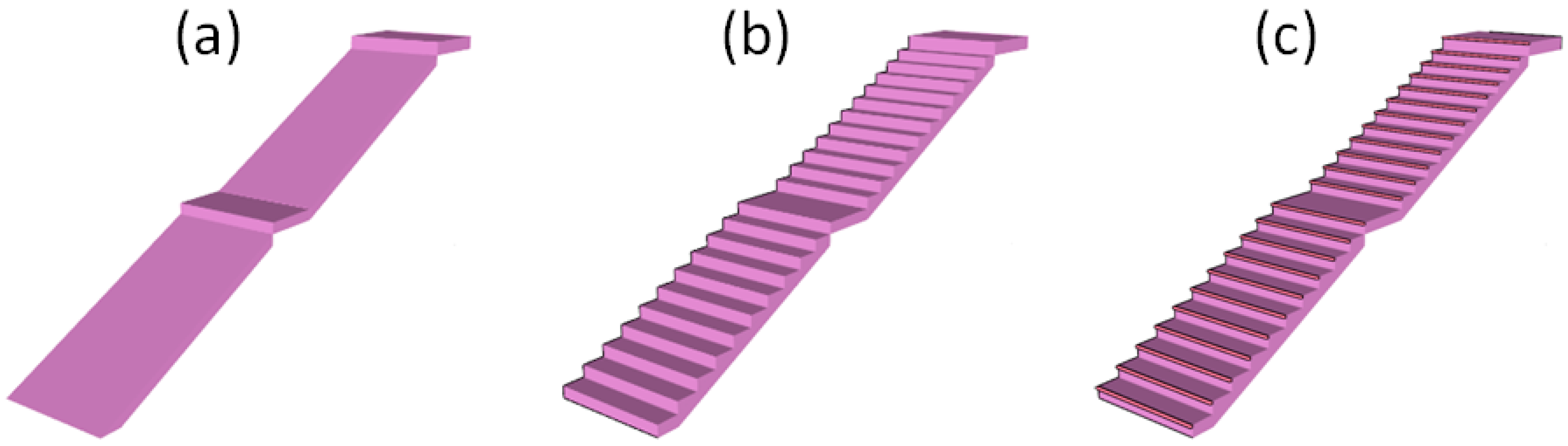
Something has to be stated that the difference of each ILoDs is not only on the existence of certain features, but also on the detail degree of their geometrical representations. The characteristic could be shown by taking the stair for example (see Figure 7), which are more and more detailed from ILoD2 to ILod4. More features could be found in the figures of Table 1. As for the concrete accuracy requirements for the features in different ILoD, it is considered as a discussion issue which needs to be laid down in further research. Additionally, several attributes, such as iLod1Geometry and iLod3ImplicitGeometry, have also been attached to the classes IntBuildingInstallation and BuildingFurniture to extend the geometrical representation for interior installation and furniture.
3.7. UML Diagram for 3D Indoor Model
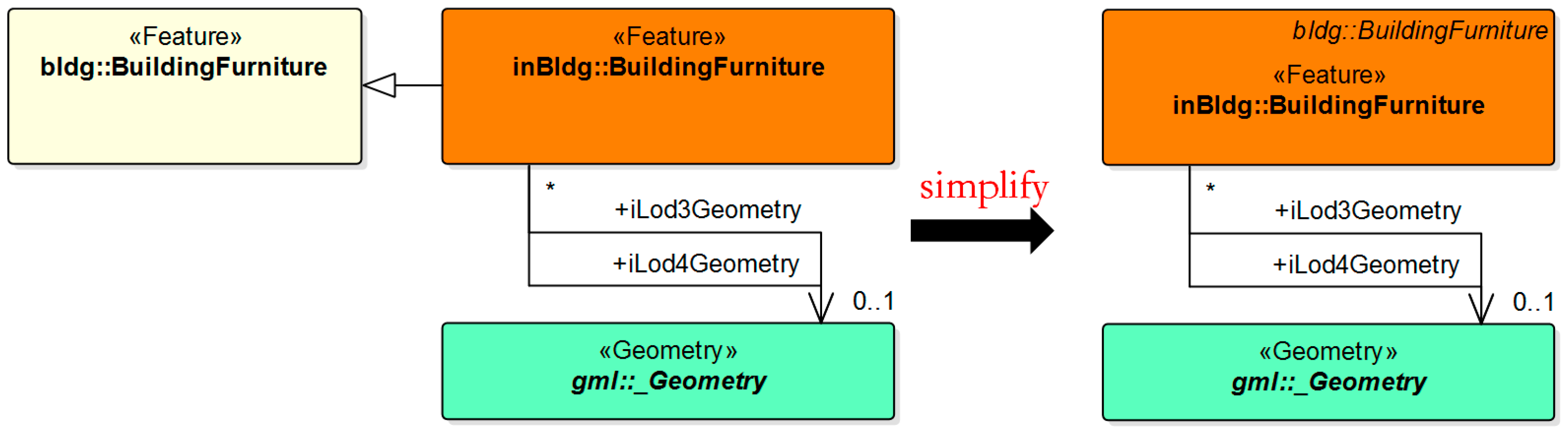
Additionally, we develop an extension for indoor scene by appending interior features to the building model of CityGML 2.0 based on its ADE mechanism, and an “inBldg” prefix is used to indicate the new XML namespace associated with these features. According to the existing OGC Best Practice recommendation for modeling ADE in UML proposed by Brink et al. [54], the extension is processed similarly. That is, we define the to-be-added properties in subclasses in the ADE package rather than the original classes directly, and then suppress these subclasses from the generated XML Schema, in order to comply with UML, ISO 19100 series, and OGC rules. Figure 8 exhibits an example in the ADE of a subclass BuildingFurniture that contains additional properties compared to the equivalent CityGML class and its simplified representation. The revised UML diagram of the building model is demonstrated as Figure 9 (for clarity, the simplified version is adopted, and some original classes and relationships are omitted).
4. Full LoD Specification for 3D Building Models
To date, the LoD for both the exterior and interior of the building model is defined from various perspectives. As the two aspects are often required simultaneously for many applications, determining how to combine them continuously and seamlessly becomes another problem to be explored. Two potential schemes of integration are shown in Figure 10, which we call full LoDs (FLoDs).
Scheme one: FLoDs = OLoDs + ILoDs.
The “+” operator here means that the ILoDs are appended to the OLoDs into a longer level sequence (the length is nine: Four OLoDs, plus five ILoDs). The alteration is substantially equivalent to subdividing the CityGML’s LoD4 into more detailed levels that follow the rules and characters of CityGML 2.0 standards for either geometry or semantics; therefore, the definition remains consistent. Unfortunately, the strong coupling of the exterior and interior of the building model remains unresolved because OLoD3 is also inherited; that is, the last interior level models cannot be used independently unless they are surrounded with the finest exterior shell; thus, the scheme is not an ideal solution.
Apart from the integrated geometrical expression, we also investigate the corresponding semantic extensions, as shown in Table 2. In CityGML 2.0, only RoofSurface, WallSurface, GroundSurface, OuterCeilingSurface, OuterFloorSurface, and ClosureSurface as subclasses of _BoundarySurface are allowed to be used starting from LoD2. In other words, substantially no concrete semantics exist in the LoD1 block model, whereas in the indoor scenario, some concepts are of relative importance, e.g., CeilingSurface, FloorSurface, and InteriorWallSurface. In addition, to better serve the integration progress, several important points must be explained further to avoid modeling confusion.
- Backward compatibility. Backward compatibility is a most important point that the developers or organizers must first consider when extending or upgrading a model. Since FLoD is proposed as a suggestion for the next CityGML version, this concept should be compatible with the five LoDs in CityGML 2.0. Table 1 indicates that the FLoD3–4 model is essentially the same as the original LoD4 model, which has both the semantically richest and geometric-topologically soundest exterior and interior. In contrast, the other four LoDs cannot directly be obtained in the FLoDs series, because the models represented in the table all have been combined with various detailed level interiors; however, these LoDs could easily be derived after a simple separation operation deleting or hiding the interior features, such as the InteriorWallSurface or the Story. Alternatively, we can consider the OLoDs to be the special models that come equipped with a null interior.
- FLoD0 (OLoD0 * ILoDs). A minor enhancement in representing the LoD0 model may arise when considering the building interior. In CityGML 2.0, the LoD0 building model can be represented by horizontal surfaces of the footprint or the roof edge. In FLoD0, another two horizontal surfaces are added, CeilingSurface and FloorSurface, which can approximately outline the height of a room or story. For a similar purpose, the projection of vertical features (e.g., wall and door) on the floor could optionally be kept to divide various indoor spaces into subspaces, such as rooms or corridors. Moreover, another character of FLoD0 is that the furniture and installations attached to the vertical features need not be represented because of the absence of attachments.
- Structure and connectivity. The structure and connectivity of certain features are treated as two different levels from the view of their functionality when classifying interior details such as door, window and stair. As an international standard, CityGML 2.0 is inclined to provide the basic-features class with few attributes to leave more space for industries to expand to higher applicable models. By this token, most features in the standard contribute their structural value in the modeling progress only. Because the connectivity of the interior spaces of building is of utmost importance for other indoor applications, it is strongly recommended to extend several classes or attributes relating to the accessibility of the rooms, corridors, or stories. As a result, some features need to embody their rough structures in ILoD1 only, and more details and states in ILoD2, for example, stair, could even be replaced by a ramp if only the overall interior structure of a building is relevant.
- Outdoor and indoor characteristics. Although the OLoD and ILoD are defined at two perspectives, the door and window retain distinct functions, as previously mentioned. In CityGML 2.0, the openings can exist in LoD3 and LoD4 models only, whereas in our proposal for indoor scenarios, the door and window are the vital structures and connections. Thus, when integrating the exterior and interior, a distinction should be made, and the isExternal attribute may solve the contradiction. This attribute allows the model with a completely closed exterior and connected interior to become possible; this model is applicable to those applications more concerned about the interior space rather than the exterior appearance of the building model.
5. Experimental Demonstrations
Note that any refinements and improvements to the current specification of the proposed concept are not intended to disrupt the pre-existing standard or generate a new theory; rather, these modifications are intended to provide a supplementary specification that has already been under consideration in the CityGML community for the new version to facilitate further research on building simulations and applications.
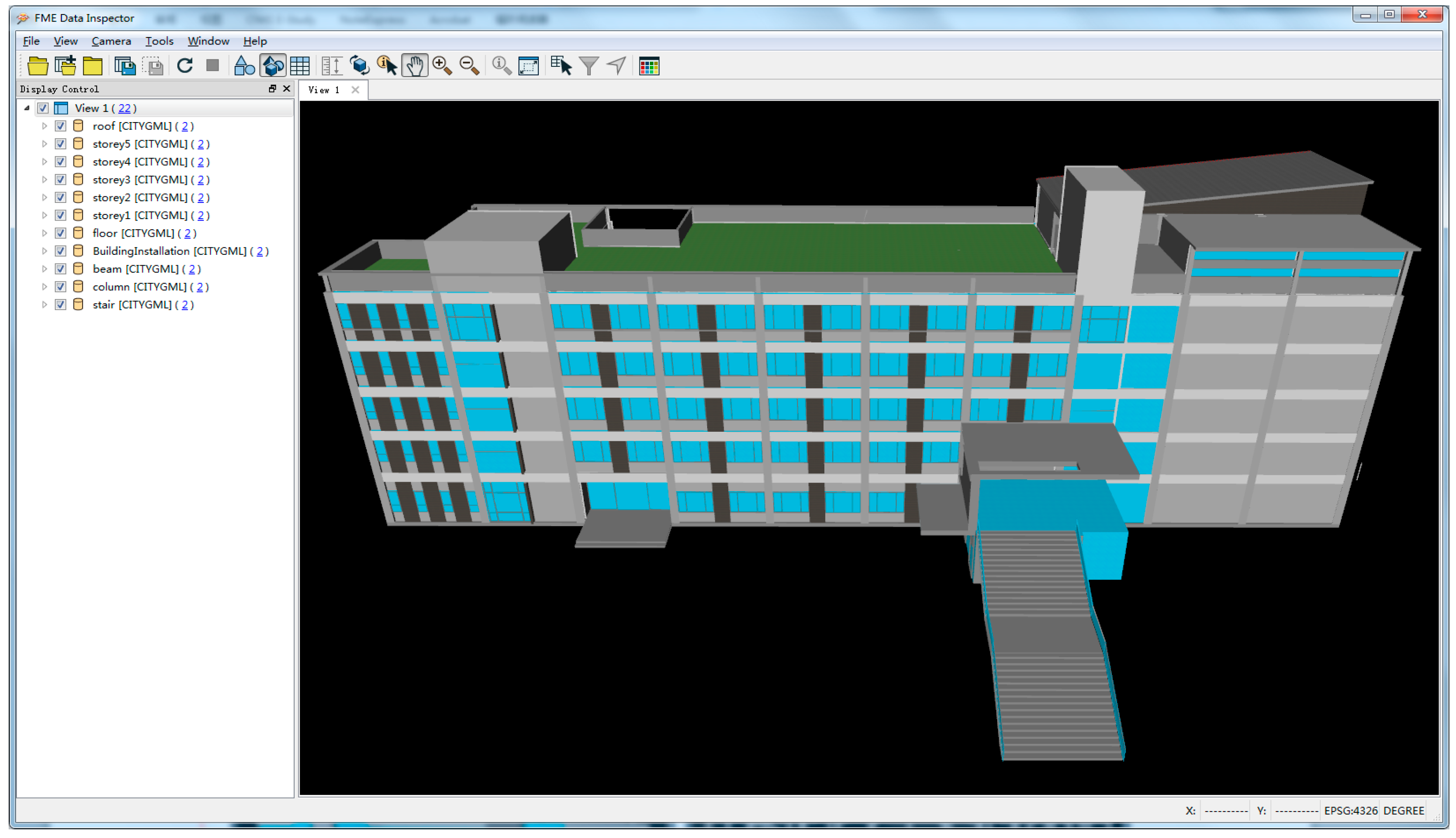
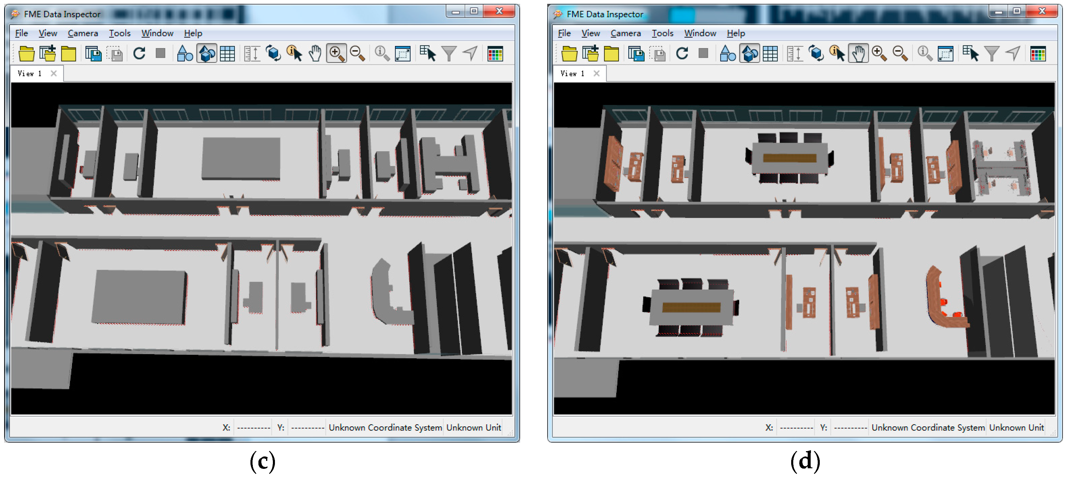
To better understand the proposed specification, an experimental demonstration on a building model, which has five stories and the internal structure of each story is similar, is provided in this section. The model data is illustrated in the CityGML software, named FME Data Inspector 2016, as shown in the following figures. Figure 11 presents an overview of the model data, the left side of the viewer is the hierarchical tree of the building components, while the right side display the 3D model related to the selected items on the left. Just like the display result in Figure 12a, only the first story and fifth story, as well as the connected stairs are selected. We could also clearly see the frame structure consisted by beams and columns of the building model from Figure 12b. Two representations for the interior furniture of ILoD3 and ILod4 are respectively presented in Figure 12c,d.
6. Conclusions and Future Work
The main objective of our study is to develop a full LoD specification for 3D building models integrating indoor and outdoor scenarios. The contributions of the proposed model to the existing body of knowledge could be summed up into twofold. The first is to make up the narrow LoD definition drawback for indoor space of CityGML 2.0 by putting forward a novel indoor LoD specification from a less detailed to a refined description. Second, based on the newly proposed indoor and outdoor LoDs, we suggest a greater set of continuous and seamless full LoDs for 3D building models from both geometrical and semantical perspectives to adapt to the different visual or analytical requirements of various applications.
The extended specification is simple and understandable because of its consistent driving motivation, organizational principle, and ultimate goal along with the use of the well-known LoD definition in CityGML 2.0. By filling the gap of the detailed interior levels of a building model, the ambiguity of exchange or transformation between data collectors, processors, and users in both outdoor and indoor modeling fields, particularly those applications that feature a relatively detailed emphasis on certain aspects of building models, can be effectively addressed. Additionally, rather than extending a series of rigid interior features, we tend more to provide an idea concept for indoor hierarchical modeling that might be a useful inspiration for the next CityGML version. For example, in the lighting application field, pipeline and lamp facilities correspond to the foundational structures that should be represented in ILoD1 for any other further analyses; e.g., the evaluation of light transmittance involving doors and windows is included in ILoD2, and the shadow calculation hindered by indoor furniture is included in ILoD3 or ILoD4.
Several aspects of the whole LoD definition process remain that could be improved; foremost among those is an optimized simplification algorithm for indoor furniture and installations that could offer better utility with a small amount of data and certain geometric characteristics rather than the current oversimplified bounding-box approach. Furthermore, we plan to also explore related research studies in the future, such as the establishment of topology relationship, data acquisition from the BIM model, volume calculation using the voxel algorithm, and indoor idiographic applications based on appropriate improved LoD models.
Author Contributions
The research was mainly performed and prepared by L.T. and L.L., who also conceived the ideas and designed the study. S.Y. contributed to analyzing the research results and L.Y. helped to review and edit the manuscript. All authors contributed to improving the paper.
Funding
This study was funded by the National Natural Science Foundation of China (41471325, 41671381), the Scientific and Technological Leading Talent Fund of National Administration of Surveying, mapping and geo-information (2014), and the Natural Science Foundation of Hubei Province (2017CFA050).
Acknowledgments
We would like to acknowledge the editor and anonymous reviewers for their constructive comments to this article, and offer fervent gratitude to the referenced experts and scholars for their valuable inspiration for this paper.
Conflicts of Interest
The authors declare no conflict of interest.
References
- Goodchild, M.F. Reimagining the history of GIS. Ann. GIS 2018, 24, 1–8. [Google Scholar] [CrossRef]
- Lawler, A.; Beheshti, S.M. Bringing Cultural Heritage out of the Shadows. Science 2003, 302, 975–977. [Google Scholar] [CrossRef] [PubMed]
- Cheng, E.W.L.; Li, H.; Yu, L. A GIS approach to shopping mall location selection. Build. Environ. 2007, 42, 884–892. [Google Scholar] [CrossRef]
- Ranzinger, M.; Gleixner, G. GIS datasets for 3D urban planning. Comput. Environ. Urban Syst. 1997, 21, 159–173. [Google Scholar] [CrossRef]
- Özgür, G.; Hua, Y.; Göçer, K. A BIM-GIS integrated pre-retrofit model for building data mapping. Build. Simul. 2016, 9, 513–527. [Google Scholar]
- Dai, F.C.; Lee, C.F.; Zhang, X.H. GIS-based geo-environmental evaluation for urban land-use planning: A case study. Eng. Geol. 2001, 61, 257–271. [Google Scholar] [CrossRef]
- Manjanatha, M.G.; Shelton, S.D.; Culp, S.J.; Blankenship, L.R.; Casciano, D.A. Land-use configuration under traditional agriculture in the Kanto Plain, Japan: A historical GIS analysis. Int. J. Geogr. Inf. Sci. 2013, 27, 68–91. [Google Scholar]
- Kulawiak, M.; Prospathopoulos, A.; Perivoliotis, L.; Łuba, M.; Kioroglou, S.; Stepnowski, A. Interactive visualization of marine pollution monitoring and forecasting data via a Web-based GIS. Comput. Geosci. 2010, 36, 1069–1080. [Google Scholar] [CrossRef]
- Devillers, R.; Bédard, Y.; Jeansoulin, R. Multidimensional Management of Geospatial Data Quality Information for its Dynamic Use within GIS. Photogramm. Eng. Remote Sens. 2005, 71, 205–216. [Google Scholar] [CrossRef]
- Gröger, G. How to achieve consistency for 3D city models. Geoinformatica 2011, 15, 137–165. [Google Scholar] [CrossRef]
- Ledoux, H.; Meijers, M. Topologically consistent 3D city models obtained by extrusion. Int. J. Geogr. Inf. Sci. 2011, 25, 557–574. [Google Scholar] [CrossRef] [Green Version]
- EPA. Buildings and Their Impact on the Environment: A Statistical Summary. 2009. Available online: http://www.epa.gov/greenbuilding/pubs/gbstats.pdf (accessed on 22 April 2009).
- Tsiliakou, E.; Dimopoulou, E. 3D Network Analysis for Indoor Space Applications. ISPRS-Int. Arch. Photogramm. Remote Sens. Spat. Inf. Sci. 2016, XLII-2/W2, 147–154. [Google Scholar] [CrossRef]
- Tashakkori, H.; Rajabifard, A.; Kalantari, M. A new 3D indoor/outdoor spatial model for indoor emergency response facilitation. Build. Environ. 2015, 89, 170–182. [Google Scholar] [CrossRef]
- Clark, J.H. Multiple Levels of Detail. 1976. Available online: http://people.cs.clemson.edu/~dhouse/courses/405/notes/OpenGL-mipmaps.pdf (accessed on 19 October 1976).
- Gröger, G.; Plümer, L. CityGML-Interoperable semantic 3D city models. ISPRS J. Photogramm. Remote Sens. 2012, 71, 12–33. [Google Scholar] [CrossRef]
- Biljecki, F. Level of Detail in 3D City Models. Ph.D. Thesis, Delft University of Technology, Delft, The Netherlands, 2003. [Google Scholar]
- OGC (Open Geospatial Consortium). City Geography Markup Language (CityGML) Encoding Standard (Version 1.0.0). 2008. Available online: http://portal.opengeospatial.org/files/?artifact_id=28802 (accessed on 20 August 2008).
- OGC (Open Geospatial Consortium). City Geography Markup Language (CityGML) Encoding Standard (Version 2.0). 2012. Available online: http://www.opengeospatial.org/standards/citygml (accessed on 4 April 2012).
- Biljecki, F.; Ledoux, H.; Stoter, J. An improved LOD specification for 3D building models. Comput. Environ. Urban Syst. 2016, 59, 25–37. [Google Scholar] [CrossRef] [Green Version]
- Hagedorn, B.; Trapp, M.; Glander, T.; Döllner, J. Towards an Indoor Level-of-Detail Model for Route Visualization. In Proceedings of the Tenth International Conference on Mobile Data Management: Systems, Services and Middleware, Taipei, Taiwan, 18–20 May 2009; pp. 692–697. [Google Scholar]
- Isikdag, U.; Zlatanova, S.; Underwood, J. A BIM-Oriented Model for supporting indoor navigation requirements. Comput. Environ. Urban Syst. 2013, 41, 112–123. [Google Scholar] [CrossRef]
- Boeters, R.; Ohori, K.A.; Biljecki, F.; Zlatanova, S. Automatically enhancing CityGML LOD2 models with a corresponding indoor geometry. Int. J. Geogr. Inf. Sci. 2015, 29, 2248–2268. [Google Scholar] [CrossRef]
- Biljecki, F.; Ledoux, H.; Stoter, J.; Zhao, J. Formalisation of the level of detail in 3D city modelling. Comput. Environ. Urban Syst. 2014, 48, 1–15. [Google Scholar] [CrossRef] [Green Version]
- Löwner, M.O.; Benner, J.; Gröger, G.; Häfele, K.H. New Concepts for Structuring 3D City Models-An Extended Level of Detail Concept for CityGML Buildings; Springer: Berlin/Heidelberg, Germany, 2013; pp. 466–480. [Google Scholar]
- Löwner, M.O.; Gröger, G.; Benner, J.; Biljecki, F.; Nagel, C. Proposal for a new LOD and multi-representation concept for CityGML. ISPRS Ann. Photogramm. Remote Sens. Spat. Inf. Sci. 2016, IV-2/W1, 3–12. [Google Scholar]
- Löwner, M.O.; Gröger, G. Evaluation Criteria for Recent LoD Proposals for CityGML Buildings. Photogramm. Fernerkund. Geoinf. 2016, 2016, 31–43. [Google Scholar] [CrossRef]
- Laakso, M.; Kiviniemi, A. The IFC Standard-A Review of History, Development, and Standardization. J. Inf. Technol. Constr. 2012, 17, 134–161. [Google Scholar]
- El-Mekawy, M.; Östman, A. Semantic Mapping: An Ontology Engineering Method for Integrating Building Models in IFC and CITYGML. In Proceedings of the 3rd ISDE Digital Earth Summit, Nessebar, Bulgaria, 12–14 June 2010. [Google Scholar]
- Laat, R.D.; Berlo, L.V. Integration of BIM and GIS: The Development of the CityGML GeoBIM Extension. In Advances in 3D Geo-Information Sciences; Springer: Berlin/Heidelberg, Germany, 2011; pp. 211–225. [Google Scholar]
- Donkers, S. Automatic Generation of CityGML LoD3 Building Models from IFC Models. Master’s Thesis, Delft University of Technology, Delft, The Netherlands, 2013. [Google Scholar]
- Nagel, C.; Stadler, A.; Kolbe, T. Conceptual Requirements for the Automatic Reconstruction of Building Information Models from Uninterpreted 3D Models. In Proceedings of the Academic Track of Geoweb 2009 Conference, Vancouver, BC, Canada, 27–31 July 2009; pp. 46–53. [Google Scholar]
- Tolmer, C.E.; Castaing, C.; Diab, Y.; Morand, D. CityGML and IFC: Going further than LOD. In Proceedings of the Digital Heritage International Congress, Marseille, France, 28 October–1 November 2013; pp. 645–648. [Google Scholar]
- Li, K.J. Indoorgml-a Standard for Indoor Spatial Modeling. Int. Arch. Photogramm. Remote Sens. Spat. Inf. Sci. 2016, XLI-B4, 701–704. [Google Scholar] [CrossRef]
- Diakité, A.A.; Zlatanova, S.; Li, K.J. About the subdivision of indoor spaces in IndoorGML. Int. Arch. Photogramm. Remote Sens. Spat. Inf. Sci. 2017, IV-4/W5, 41–48. [Google Scholar]
- Ryoo, H.G.; Kim, T.; Li, K.J. Comparison between two OGC standards for indoor space: CityGML and IndoorGML. In Proceedings of the ACM Sigspatial International Workshop on Indoor Spatial Awareness, Bellevue, WA, USA, 3 November 2015; p. 1. [Google Scholar]
- Kim, J.S.; Yoo, S.J.; Li, K.J. Integrating IndoorGML and CityGML for Indoor Space. In Proceedings of the International Symposium on Web and Wireless Geographical Information Systems, Seoul, Korea, 29–30 May 2014; pp. 184–196. [Google Scholar]
- Zhu, Q.; Li, Y.; Xiong, Q.; Zlatanova, S.; Ding, Y.; Zhang, Y.; Zhou, Y. Indoor Multi-Dimensional Location GML and Its Application for Ubiquitous Indoor Location Services. Int. J. Geo-Inf. 2016, 5, 220. [Google Scholar] [CrossRef]
- Ekholm, A.; Fridqvist, S. A concept of space for building classification, product modelling, and design. Autom. Constr. 2000, 9, 315–328. [Google Scholar] [CrossRef]
- Rivard, H.; Mora, R.; Bédard, C. Computer Representation to Support Conceptual Structural Design within a Building Architectural Context. J. Comput. Civ. Eng. 2006, 20, 76–87. [Google Scholar]
- Lertlakkhanakul, J.; Jin, W.C.; Mi, Y.K. Building data model and simulation platform for spatial interaction management in smart home. Autom. Constr. 2008, 17, 948–957. [Google Scholar] [CrossRef]
- Mora, R.; Bédard, C.; Rivard, H. A geometric modelling framework for conceptual structural design from early digital architectural models. Adv. Eng. Inform. 2008, 22, 254–270. [Google Scholar] [CrossRef]
- Björk, B.C. A conceptual model of spaces, space boundaries and enclosing structures. Autom. Constr. 1992, 1, 193–214. [Google Scholar] [CrossRef]
- Brown, G.; Nagel, C.; Zlatanova, S.; Kolbe, T.H. Modelling 3D Topographic Space Against Indoor Navigation Requirements; Springer: Berlin/Heidelberg, Germany, 2013; pp. 1–22. [Google Scholar]
- Merrell, P.; Schkufza, E.; Li, Z.; Agrawala, M.; Koltun, V. Interactive furniture layout using interior design guidelines. ACM Trans. Graph. 2011, 30, 1–10. [Google Scholar] [CrossRef]
- Li, L.; Tang, L.; Zhu, H.; Zhang, H.; Yang, F.; Qin, W. Semantic 3D Modeling Based on CityGML for Ancient Chinese-Style Architectural Roofs of Digital Heritage. ISPRS Int. J. Geo-Inf. 2017, 6, 132. [Google Scholar] [CrossRef]
- Diakité, A.A.; Zlatanova, S. Extraction of the 3D free space from building models for indoor navigation. In Proceedings of the 3D Geoinfo Conference, Athens, Greece, 20–21 October 2016. [Google Scholar]
- Diakité, A.A.; Zlatanova, S. Valid Space Description in BIM for 3D Indoor Navigation. Int. J. 3D Inf. Model. 2016, 5, 1–17. [Google Scholar] [CrossRef]
- Teo, T.A.; Cho, K.H. BIM-Oriented Indoor Network Model for Indoor and Outdoor Combined Route Planning; Elsevier Science Publishers B.V.: Amsterdam, The Netherlands, 2016; pp. 268–282. [Google Scholar]
- Boguslawski, P.; Mahdjoubi, L.; Zverovich, V.; Fadli, F. Automated construction of variable density navigable networks in a 3D indoor environment for emergency response. Autom. Constr. 2016, 72, 115–128. [Google Scholar] [CrossRef] [Green Version]
- Kemec, S.; Zlatanova, S.; Duzgun, S. A new LoD definition hierarchy for 3D city models used for natural disaster risk communication tool. In Proceedings of the International Conference on Cartography & GIS, Albena, Bulgaria, 18–22 June 2012. [Google Scholar]
- Kang, H.Y.; Lee, J. A Study on the LOD(Level of Detail) Model for Applications based on Indoor Space Data. J. Korean Soc. Surv. Geod. Photogramm. Cartogr. 2014, 32, 143–151. [Google Scholar] [CrossRef] [Green Version]
- Billen, R.; Zaki, C.; Servières, M.; Moreau, G.; Hallot, P. Developing an ontology of space: Application to 3D city modeling. Usage, Usability, and Utility of 3d City MODELS-European Cost Action Tu. In Proceedings of the European Cost Action TU801 Final Conference, Nantes, France, 29–31 October 2012; p. 2007. [Google Scholar]
- Brink, L.; Stoter, J.; Zlatanova, S. UML-Based Approach to Developing a CityGML Application Domain Extension. Trans. GIS 2013, 17, 920–942. [Google Scholar] [CrossRef]
Figure 1.
Simulation of the layout of shelves in a supermarket.
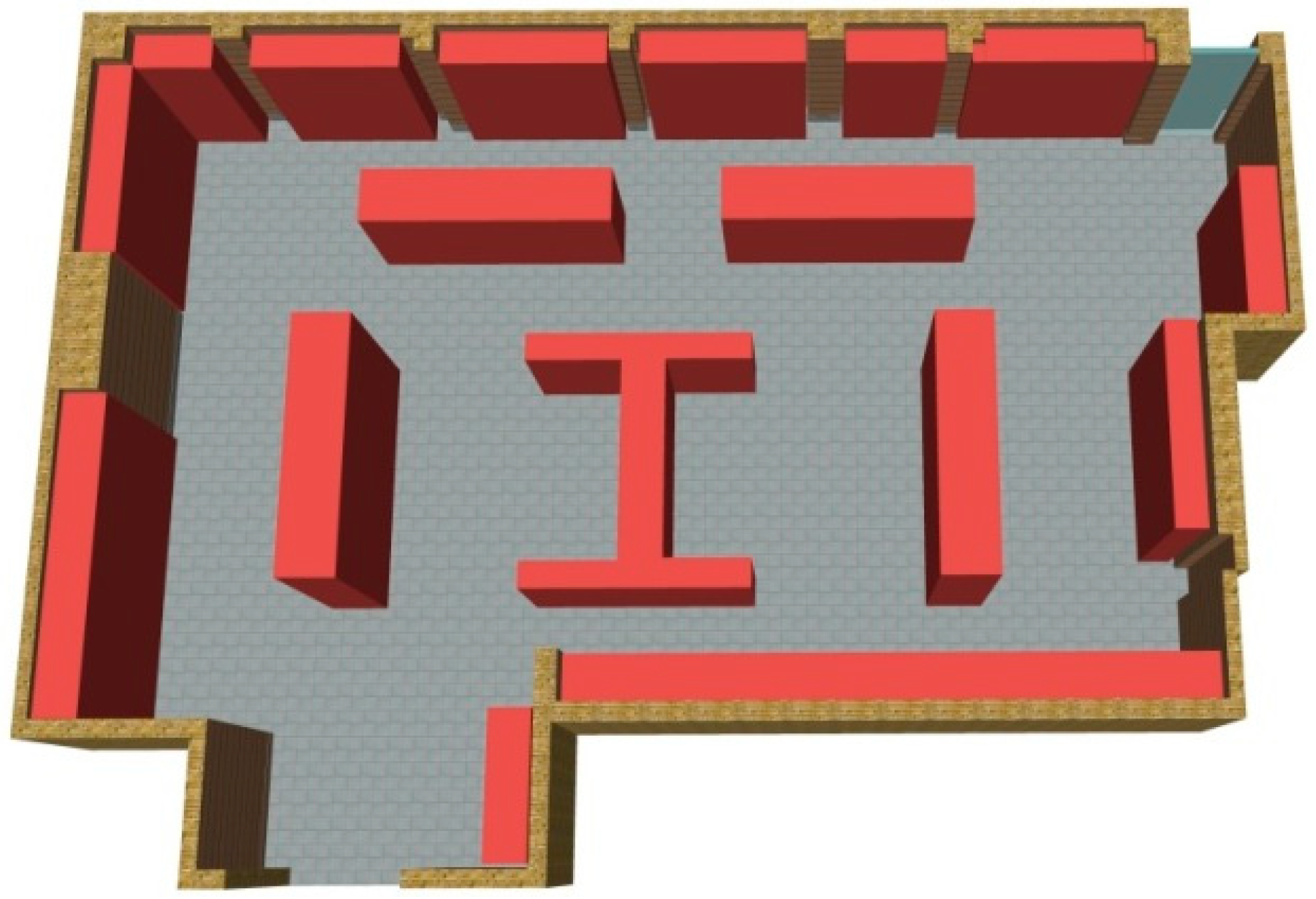
Figure 2.
Research route of full level of detail (LoD) specification for 3D building models. IFC, (industry foundation classes); ILoD (indoor LoD); OLoD (outdoor LoD).
Figure 2.
Research route of full level of detail (LoD) specification for 3D building models. IFC, (industry foundation classes); ILoD (indoor LoD); OLoD (outdoor LoD).

Figure 3.
ILoD0, the coarsest representation of the building-interior model.
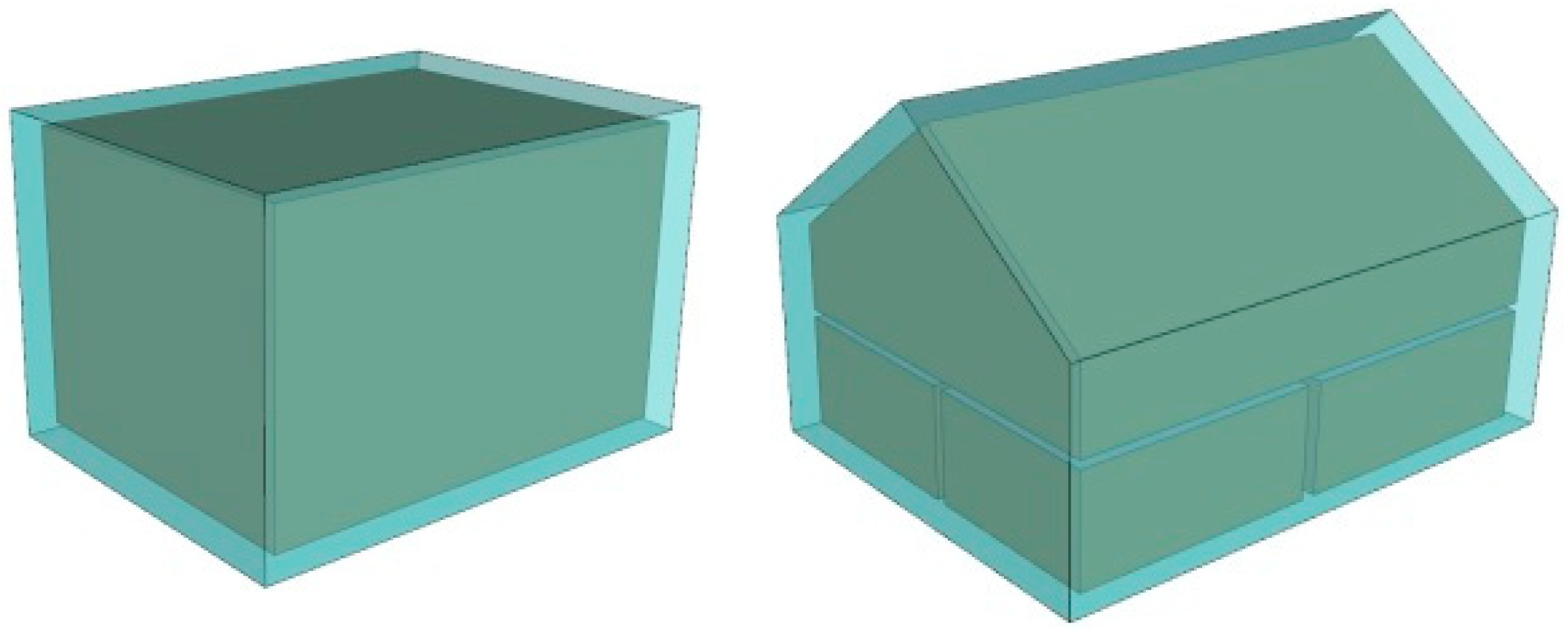
Figure 4.
Interior representation of structures in ILoD1.
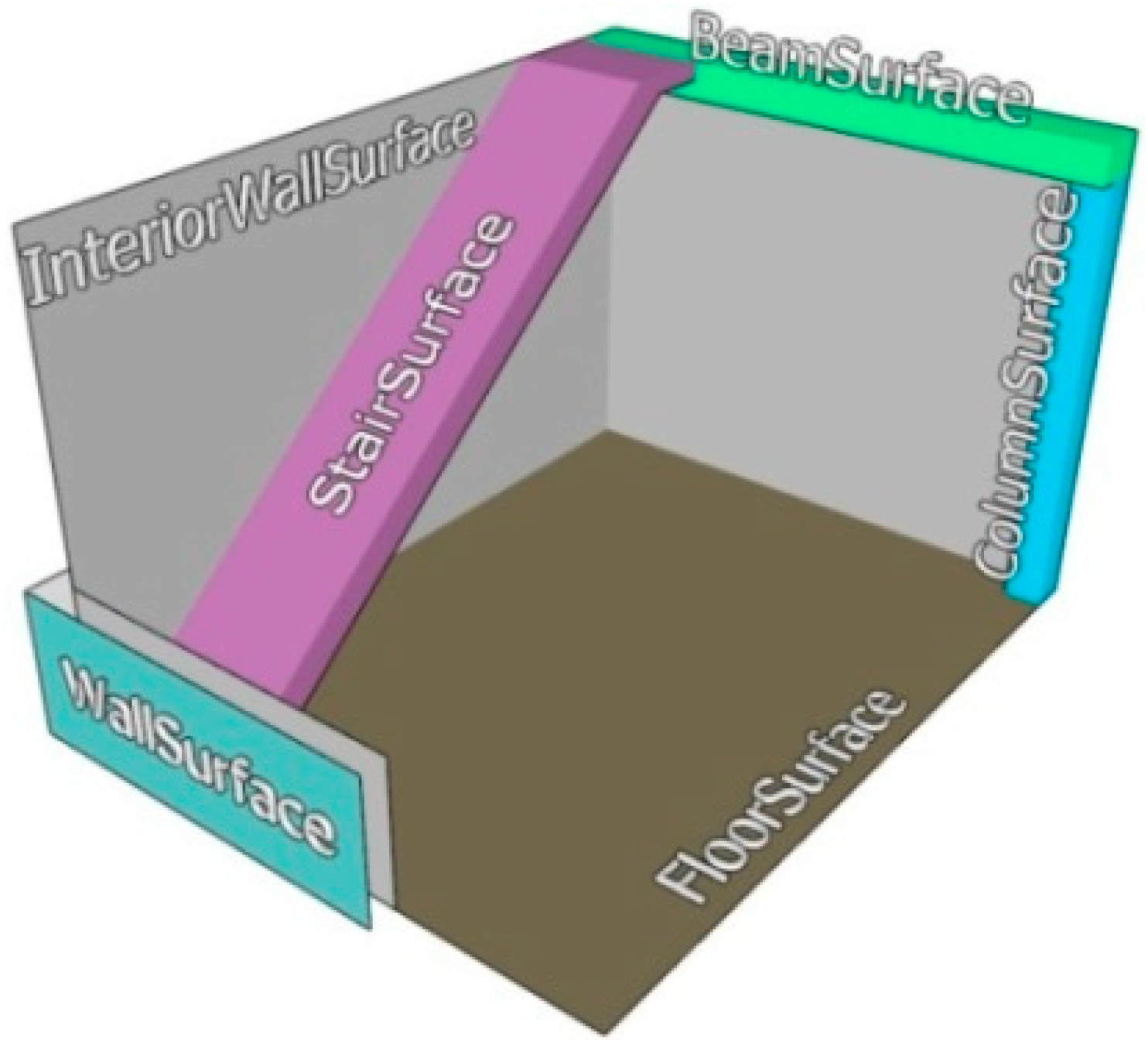
Figure 5.
Different states of a door or window.

Figure 6.
The aligned axis bounding box (AABB) simplified representation of furniture.

Figure 7.
Different geometrical representations for stair in (a) ILoD2; (b) ILoD3; and (c) ILoD4.

Figure 8.
The subclass BuildingFurniture in application domain extension (ADE) that contains additional properties compared to the equivalent CityGML class, and its simplified version.
Figure 8.
The subclass BuildingFurniture in application domain extension (ADE) that contains additional properties compared to the equivalent CityGML class, and its simplified version.

Figure 9.
CityGML ADE mechanism for the interior of the building model (for the full-color version, readers are referred to the electronic version of this paper).
Figure 9.
CityGML ADE mechanism for the interior of the building model (for the full-color version, readers are referred to the electronic version of this paper).
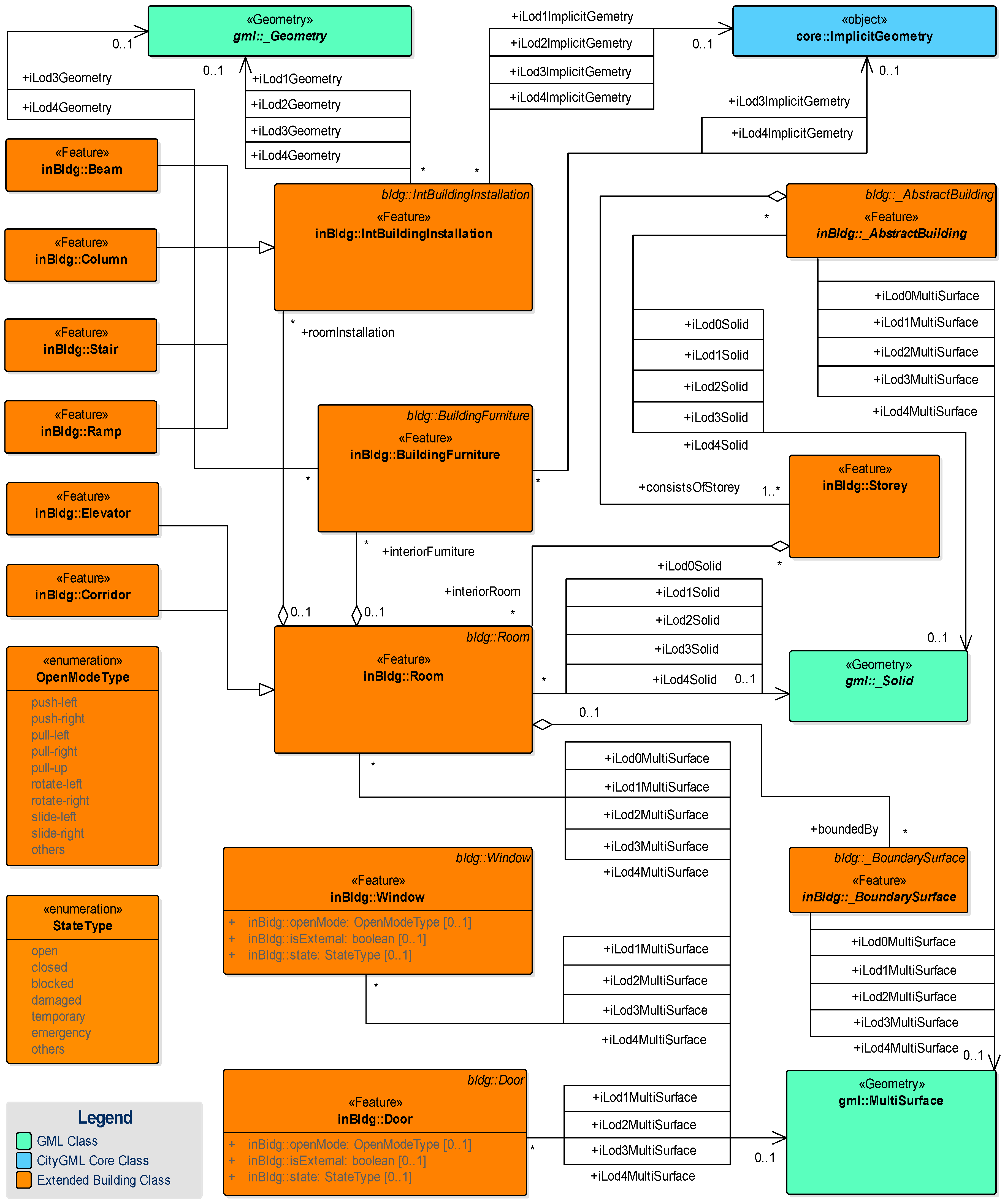
Figure 10.
Two potential schemes of the connection between OLoDs and ILoDs.
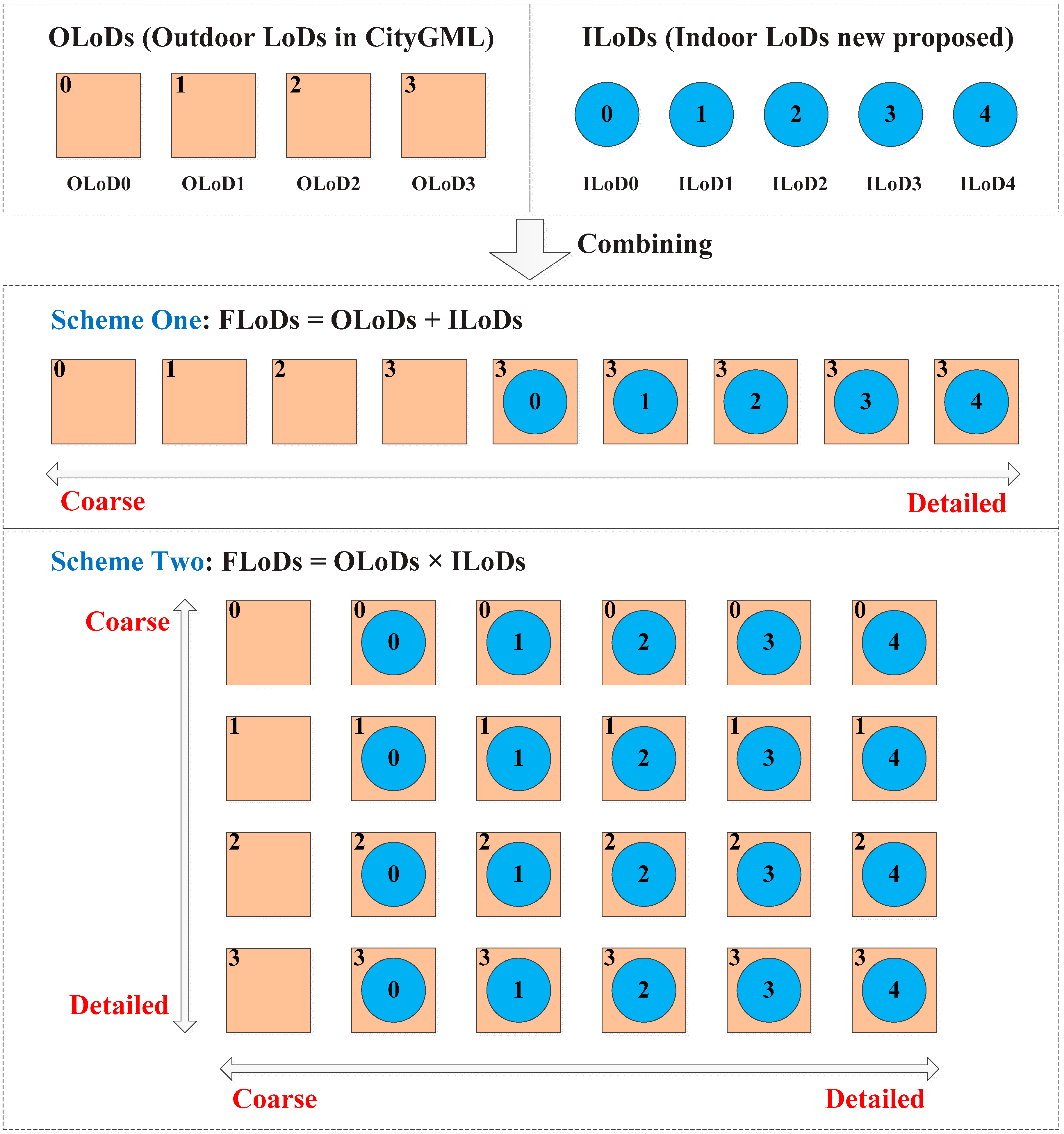
Figure 11.
An overview of building model in FME Data Inspector.

Figure 12.
Experimental demonstrations. (a) The first and fifth story; (b) the frame structure; (c) representation for the interior furniture in ILoD 3; (d) representation for the interior furniture in ILoD 4.
Figure 12.
Experimental demonstrations. (a) The first and fifth story; (b) the frame structure; (c) representation for the interior furniture in ILoD 3; (d) representation for the interior furniture in ILoD 4.


Table 1.
Geometrical representations for building models in different full LoDs (FLoDs).
| FLoDs | ILoD0 | ILoD 1 | ILoD 2 | ILoD 3 | ILoD 4 |
|---|---|---|---|---|---|
| OLoD0 |  |  |  |  |  |
| OLoD1 |  |  |  |  |  |
| OLoD2 |  |  |  |  |  |
| OLoD3 |  |  |  |  |  |
Table 2.
Semantic representations for building models in different FLoDs.
| Features | FLoDs 1 | ||||||||||||||||||||
|---|---|---|---|---|---|---|---|---|---|---|---|---|---|---|---|---|---|---|---|---|---|
| 0-0 | 0-1 | 0-2 | 0-3 | 0-4 | 1-0 | 1-1 | 1-2 | 1-3 | 1-4 | 2-0 | 2-1 | 2-2 | 2-3 | 2-4 | 3-0 | 3-1 | 3-2 | 3-3 | 3-4 | ||
| Roof | - | - | - | - | - | - | - | - | - | - | ● | ● | ● | ● | ● | ● | ● | ● | ● | ● | |
| Ceiling | ● | ● | ● | ● | ● | ● | ● | ● | ● | ● | ● | ● | ● | ● | ● | ● | ● | ● | ● | ● | |
| Floor | ● | ● | ● | ● | ● | ● | ● | ● | ● | ● | ● | ● | ● | ● | ● | ● | ● | ● | ● | ● | |
| Ground | ● | ● | ● | ● | ● | ● | ● | ● | ● | ● | ● | ● | ● | ● | ● | ● | ● | ● | ● | ● | |
| Story | ● | ● | ● | ● | ● | ● | ● | ● | ● | ● | ● | ● | ● | ● | ● | ● | ● | ● | ● | ● | |
| Room | ○ | ○ | ○ | ○ | ○ | ● | ● | ● | ● | ● | ● | ● | ● | ● | ● | ● | ● | ● | ● | ● | |
| Corridor | ○ | ○ | ○ | ○ | ○ | ● | ● | ● | ● | ● | ● | ● | ● | ● | ● | ● | ● | ● | ● | ● | |
| BuildingInstallation | - | - | - | - | - | - | - | - | - | - | ● | ● | ● | ● | ● | ● | ● | ● | ● | ● | |
| Wall | ○ | ○ | ○ | ○ | ○ | ● | ● | ● | ● | ● | ● | ● | ● | ● | ● | ● | ● | ● | ● | ● | |
| Window | - | - | - | - | - | - | ● | ● | ● | ● | - | ● | ● | ● | ● | ● | ● | ● | ● | ● | |
| Door | - | ○ | ○ | ○ | ○ | - | ● | ● | ● | ● | - | ● | ● | ● | ● | ● | ● | ● | ● | ● | |
| Column | - | ○ | ○ | ○ | ○ | - | ● | ● | ● | ● | - | ● | ● | ● | ● | - | ● | ● | ● | ● | |
| Beam | - | ○ | ○ | ○ | ○ | - | ● | ● | ● | ● | - | ● | ● | ● | ● | - | ● | ● | ● | ● | |
| Ramp | - | ○ | - | - | - | - | ● | - | - | - | - | ● | - | - | - | - | ● | - | - | - | |
| Stair | - | - | ● | ● | ● | - | - | ● | ● | ● | - | - | ● | ● | ● | - | - | ● | ● | ● | |
| Elevator | - | - | ● | ● | ● | - | - | ● | ● | ● | - | - | ● | ● | ● | - | - | ● | ● | ● | |
| BuildingFurniture (block) | Ceiling-attached | - | - | - | ● | - | - | - | - | ● | - | - | - | - | ● | - | - | - | - | ● | - |
| Wall-attached | - | - | - | - | - | - | - | - | ● | - | - | - | - | ● | - | - | - | - | ● | - | |
| Floor-attached | - | - | - | ● | - | - | - | - | ● | - | - | - | - | ● | - | - | - | - | ● | - | |
| BuildingFurniture | Ceiling-attached | - | - | - | - | ● | - | - | - | - | ● | - | - | - | - | ● | - | - | - | - | ● |
| Wall-attached | - | - | - | - | - | - | - | - | - | ● | - | - | - | - | ● | - | - | - | - | ● | |
| Floor-attached | - | - | - | - | ● | - | - | - | - | ● | - | - | - | - | ● | - | - | - | - | ● | |
1 The symbol in the table represents the existence of the feature in corresponding FLoD. “●” and “-” denote the feature exists or not, while “○” denotes the feature exists but in the form of its projection.
© 2018 by the authors. Licensee MDPI, Basel, Switzerland. This article is an open access article distributed under the terms and conditions of the Creative Commons Attribution (CC BY) license (http://creativecommons.org/licenses/by/4.0/).
Share and Cite
MDPI and ACS Style
Tang, L.; Li, L.; Ying, S.; Lei, Y. A Full Level-of-Detail Specification for 3D Building Models Combining Indoor and Outdoor Scenes. ISPRS Int. J. Geo-Inf. 2018, 7, 419. https://0-doi-org.brum.beds.ac.uk/10.3390/ijgi7110419
AMA Style
Tang L, Li L, Ying S, Lei Y. A Full Level-of-Detail Specification for 3D Building Models Combining Indoor and Outdoor Scenes. ISPRS International Journal of Geo-Information. 2018; 7(11):419. https://0-doi-org.brum.beds.ac.uk/10.3390/ijgi7110419
Chicago/Turabian StyleTang, Lei, Lin Li, Shen Ying, and Yuan Lei. 2018. "A Full Level-of-Detail Specification for 3D Building Models Combining Indoor and Outdoor Scenes" ISPRS International Journal of Geo-Information 7, no. 11: 419. https://0-doi-org.brum.beds.ac.uk/10.3390/ijgi7110419
Note that from the first issue of 2016, this journal uses article numbers instead of page numbers. See further details here.