1. Introduction
In Augmented Reality (AR), virtual objects are superimposed on a real-world view observed by a user. The main requirement for an immersive AR application is correct spatial alignment between the real-world objects and virtual ones, which means that the virtual objects must be placed in the same coordinate system as the real objects. If the camera moves, their 2D projections on the screen must move accordingly. To achieve this, a precise camera pose, relative to the world coordinate system, must be known. This process is often called camera pose estimation or camera tracking.
Multiple camera tracking methods are available, such as magnetic, inertial, GPS-based, vision, and other methods [
1]. Inasmuch as our interest is in cultural heritage interiors, usually guarded by rigorous conservatory policies, we focus on a vision-based camera tracking algorithm, which does not require physical integration into the interior geometry, as compared with alternative solutions that employ external tracking devices. Moreover, we consider only the visible-light spectrum because the use of infrared light may be dangerous for pigments used to paint the walls [
2].
In recent years, 3D scanning has become an increasingly popular technique in cultural heritage documentation. Until now, many cultural heritage sites have been digitized using different techniques such as laser scanning [
3], Digital Photogrammetry (DP) in which the Structure from Motion (SfM) algorithm is widely used [
4], or structured light [
2] resulting in precise 3D documentation. These high-quality scans may be used in model-based camera tracking algorithms to create specialized AR applications.
The aim of our work is to develop an AR system called Camera Tracking for Cultural Heritage Applications (CATCHA) with the following functionalities.
It should work on any interior model, both planar and non-planar, regardless of its registration technique. The solution should depend only on point cloud data.
It should work in a wide range of object distances from 0.5 to 2 m.
It should be as simple as possible. Neither input data/parameters nor any configuration and initialization in a known initial position should be required from the user.
It should work in real-time, i.e., it must have an interactive frame rate of at least 15 Hz on a mobile device.
It should not use any artificial markers.
It should exhibit stable visualization with negligible drift and jitter.
To our knowledge, no system has been developed that satisfies all these requirements. CATCHA was implemented and tested in two real cultural heritage interiors scanned using structured light and laser techniques.
Our paper is organized as follows. Related work is presented in the next section, and
Section 3 presents the materials used in the investigation. The details of our method are provided in
Section 4. Verification of the algorithm on real data and the results are presented in
Section 5 and discussed in
Section 6, respectively. The last section contains our conclusions.
2. Related Work
Markerless camera tracking approaches can be divided into two main categories [
5]: relative (image based) and tracking-by-detection (model based). A summary of these approaches is listed in
Table 1. The first category exploits frame-to-frame spatiotemporal information to determine the camera motion between frames. This approach is very sensitive to occlusions and rapid camera movements, and suffers from drift because of the accumulation of tracking errors. It does not require a model of the tracked object to be known beforehand. On the other hand, the tracking-by-detection approach requires a model and relies on extracted features (points, lines, etc.) from both the model and current camera frames. They are independently matched in every frame, and thus, this method does not suffer from the drift effect and can handle partial occlusions and rapid camera movements at the cost of higher computational complexity.
Combined approaches are also available, such as in [
6], that employ relative tracking to track the camera motion between consecutive frames and the tracking-by-detection approach to recover from tracking failures and compensate the drift.
We are also aware of the SLAM (simultaneous localization and mapping) [
7] based methods that simultaneously track the camera pose and compute the geometry of the surrounding environment. Therefore, it does not depend on a predefined model. However, extracting the real-world scale information from a SLAM-based system may be challenging. Further, displaying a specific object content is not directly possible. Thus, model-based tracking is more suitable.
As mentioned earlier, three main techniques are available in capturing point clouds in cultural heritage applications, but many model-based camera tracking algorithms require the model to be built using one particular method. For example, in the last decade, an enormous progress in SfM-based location recognition was achieved [
8,
9]. In addition, some approaches are available that estimate the camera pose based on laser scans. Although very accurate, they are not suitable for real-time applications [
10,
11].
With regard to general point cloud based camera pose estimation algorithms, Wu et al. [
12] proposed a method to extract SIFT (Scale Invariant Feature Transform) [
13] descriptors out of orthonormalized patches that exploit the 3D normal direction of a single patch. However, their approach relies on fronto-parallel surfaces for an initial match, and features are then extracted relative to this direction. This algorithm was originally designed to interactively compute the camera pose in a single query image. However, large errors may be produced when the camera is close to the object surface, as presented in [
14], and thus fail to fulfill Requirement No. 2 presented earlier.
Jaramillo et al. [
15] proposed a framework that uses a point cloud constructed by an RGBD sensor and thereafter only uses a monocular camera to estimate the pose. In contrast to the SLAM-based approaches, this solution does not track points from frame to frame. Instead, previous poses are only used to limit the search space. Their solution was reported to work at only approximately 3 Hz. Therefore, Requirement No. 4 is not satisfied.
Crombez et al. [
16] used laser scanners to create a dense point cloud model of an interior and then used a fisheye camera and synthetic views to localize its position. However, their method requires a manual initialization step. This solution does not fulfill Requirement No. 3.
Probably, a solution most similar to that presented in this paper is the work from Rambach et al. [
17]. They rendered approximately 10000 training images of a model and then chose the best matching set. Subsequently, they used relative tracking combined with the tracking-by-detection approach to recover from tracking failure. In the event of a tracking failure, their initialization procedure takes more than 100 ms, which may be visible as a frame drop; thus, their approach may not satisfy Requirement No. 6 in some circumstances.
With respect to markerless camera tracking algorithms in cultural heritage, many solutions rely on available libraries and track only the planar structures in the scene. To name a few, Vanoni et al. [
18] created a visual see-through AR application that maps multimodal data on a renascence fresco in Florence, Italy. Their solution relies on the Vuforia [
19] library. Gîrbacia et al. [
20] used AR to recreate sculptures in the Black Church in Brasov, Romania. In their project, the Instant Player library [
21] was used. Verykokou et al. [
22] used specially designed algorithm to track the feature points on a planar wall to recreate an ancient stoa in Athens, Greece. All mentioned solutions track only planar structures; thus, they do not satisfy Requirement No. 1. Battini and Laudi [
23] tracked a statue of Leonardo da Vinci in Milan, Italy. In their project, ARmedia SDK [
24] was used. Compared with the approaches mentioned earlier, this library allows 3D camera tracking based on object texture and non-planar geometry but requires time-consuming manual data preparation and algorithm parameters tuning; thus, Requirement No. 3 is not satisfied.
3. Materials
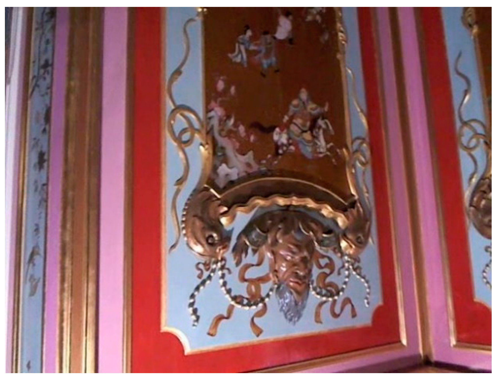
Our algorithm was used to track the camera pose in the King’s Chinese Cabinet in the Museum of King Jan III’s Palace at Wilanów, Warsaw, Poland. This interior was scanned using structured light technique in 2009 shortly before renovation, and scanned again in 2015 [
2].
Figure 1 shows the visual comparison between these two scans. The point cloud registered in 2009 contains 4 billion points and was scanned using SLR cameras, and that registered in 2015 contains 35 billion points and was scanned using industrial cameras with color calibration [
25]. In both scans, every point contains its position, color, normal vector, and quality value that represents the certainty of a registered point. Based on these two scans, we designed an AR application that allows a user to see the previous state of the Cabinet. Additional tests were performed on the Al Fresco Cabinet in the same museum. This interior was scanned once using the FARO Focus3D X130 HDR time-of-flight (TOF) laser scanner. The cloud contains 172 million points and has the same internal structure.
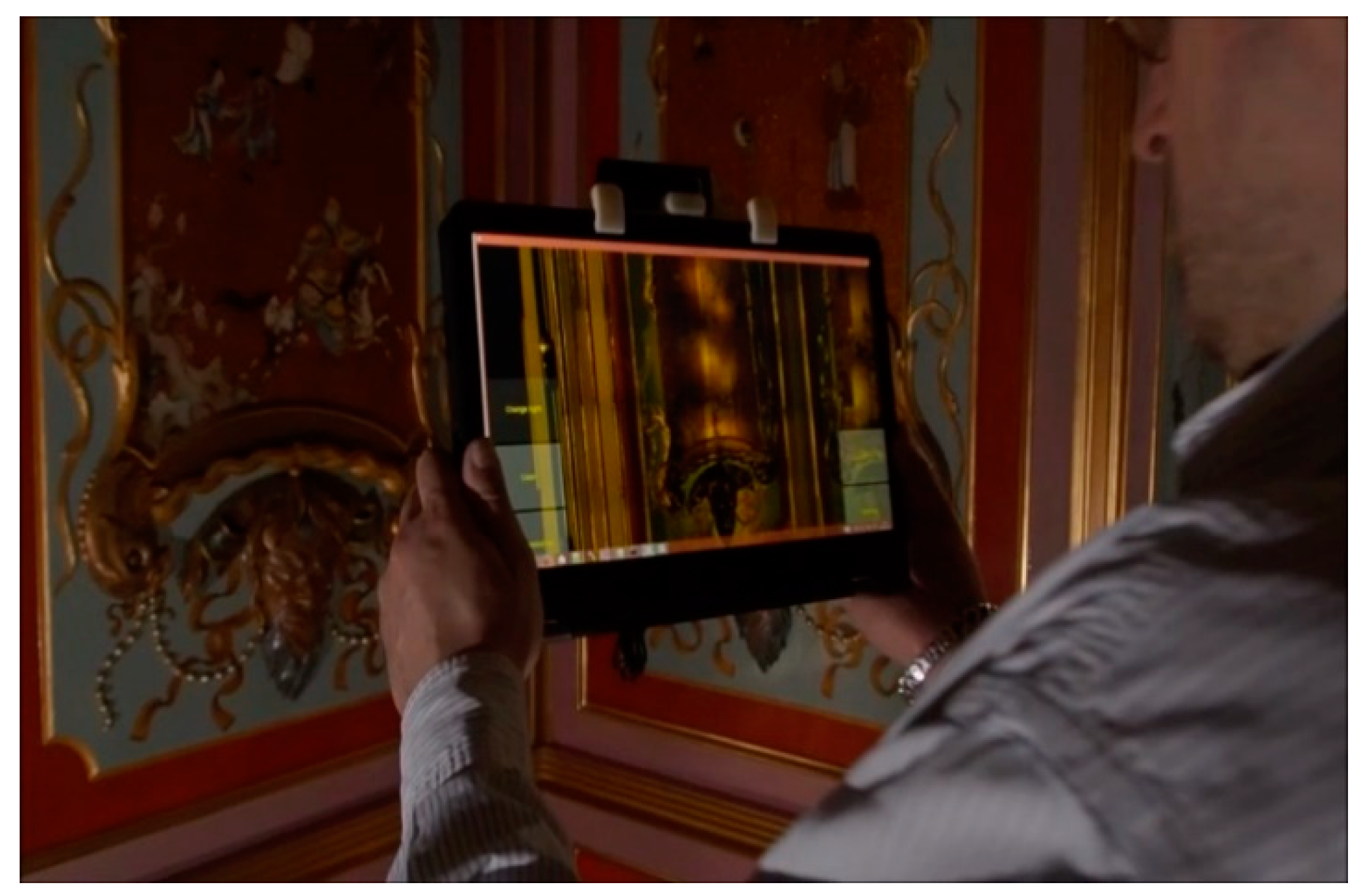
In our camera tracking solution, we used a single Logitech B910 camera with the resolution reduced from 1920 × 1080 pixels to 640 × 480 pixels (
Figure 2 shows a sample frame). We connected it to a Lenovo Yoga convertible laptop with Intel i5-5200U 2,20 GHz processor and Nvidia GT 840M graphics card. We implemented our solution using Microsoft Visual Studio 2015 in C++ and OpenCV library on the Windows 8.1 Operating System. We also tested the streaming version of our approach, in which only the image acquisition and final model rendering were performed on the device, and all processing algorithms were remotely executed on a PC with Intel i7-6700K 4.0-GHz processor and Nvidia GeForce 960 (see
Section 3 for details). For streaming, we decided to separately send every frame with optional JPEG-LS compression realized using the CharLS library [
26]. The application based on CATCHA is shown in
Figure 3.
4. Method
To track the camera pose relative to the model, we must determine rotation matrix
and translation vector
of the camera in the model coordinate system in each frame. Given camera intrinsic matrix
from the calibration and a set of correspondences between 3D model points
and image points
, both in homogeneous coordinates, we must determine the camera extrinsic matrix that minimizes the reprojection error between
and projected model points
.
Therefore, to determine the camera pose, valid 3D–2D correspondences between the 2D points in the current camera image and the 3D model points must be known.
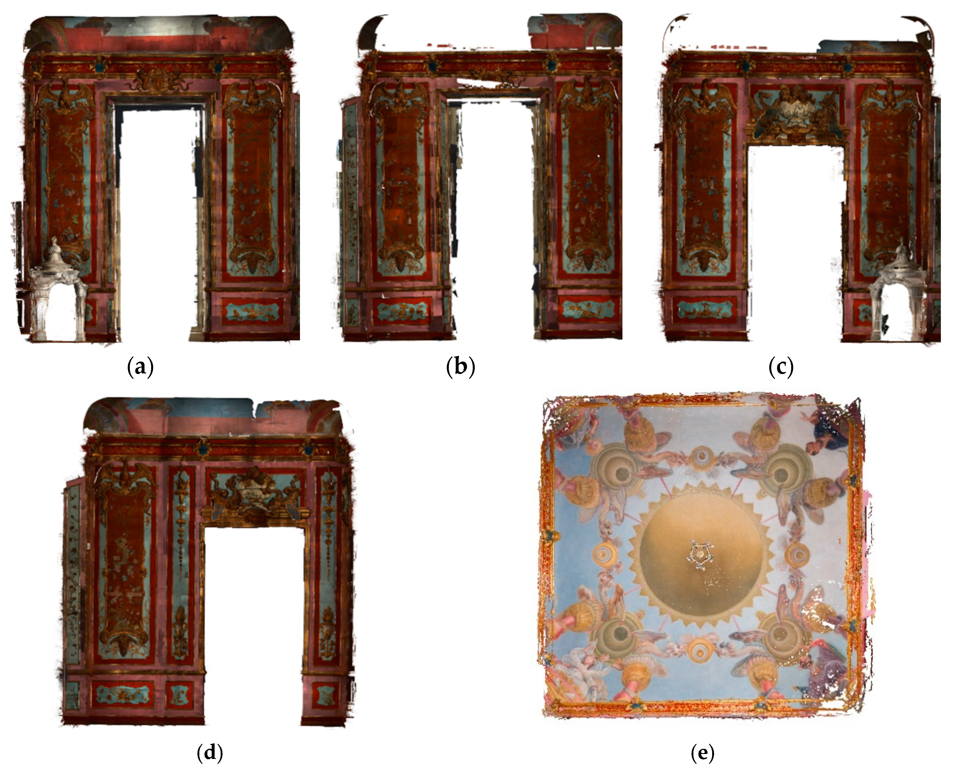
We assume that CATCHA can work on any point cloud-based data without prior knowledge of their origin. We consider three main sources of the clouds of points: structured light, TOF, and DP. To achieve model origin invariance, we decide to generate high-resolution orthographic renders (
Figure 4) with the associated 3D coordinates in every pixel using an approach similar to that in [
12].
We segment the point cloud using normal vectors to search for suitable nearly planar surfaces. Then we place the virtual orthographic camera in front of each planar area and render it. In the case of two analyzed interiors, five orthomaps are generated for each interior. If an interior has more complicated geometry, more orthomaps have to be generated. On each render, we extract the keypoints and their descriptors. In our case, the SIFT descriptor extracted by the GPU is used, but we can exploit any descriptor by taking advantage of considerably faster binary descriptors (e.g., ORB [
27]) if necessary. Because we store the 3D coordinates of each pixel, we can easily obtain the 3D–2D correspondences between each point found in the orthomap and the associated model point.
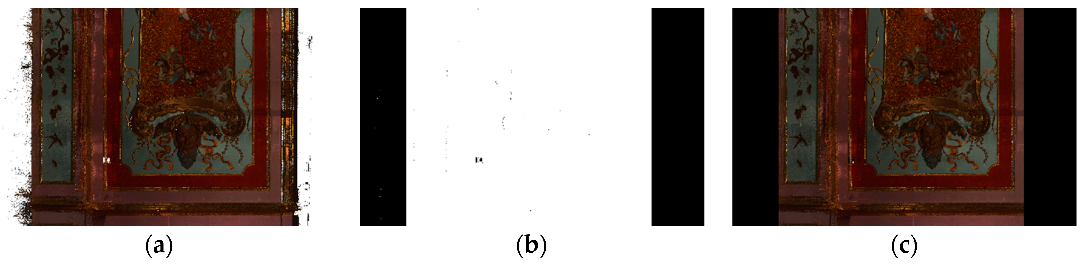
This approach leads us to a sparse interior model regardless of the initial point cloud density. In our case, we only extract a few thousand keypoints to cover the entire interior geometry. Further, reduction in the model complexity can be achieved by creating masks on the orthomaps (
Figure 5). Mask is a simple binary image with the same size as the orthomap. The black areas on the mask indicate that these areas are rejected from further processing. The purpose of this process is to filter out points and areas of noise and the noise near the borders between the model and its background, as well as the reflective or transparent fragments of a surface. The masks have to be created by the user. We used a semi-automated method based on hue to filter the areas.
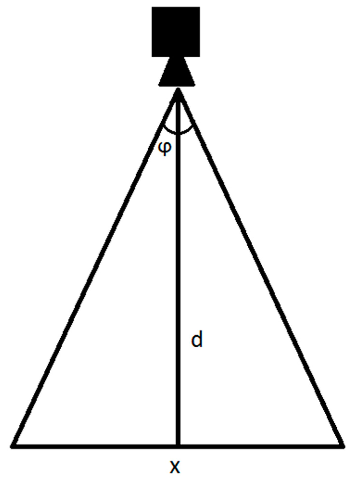
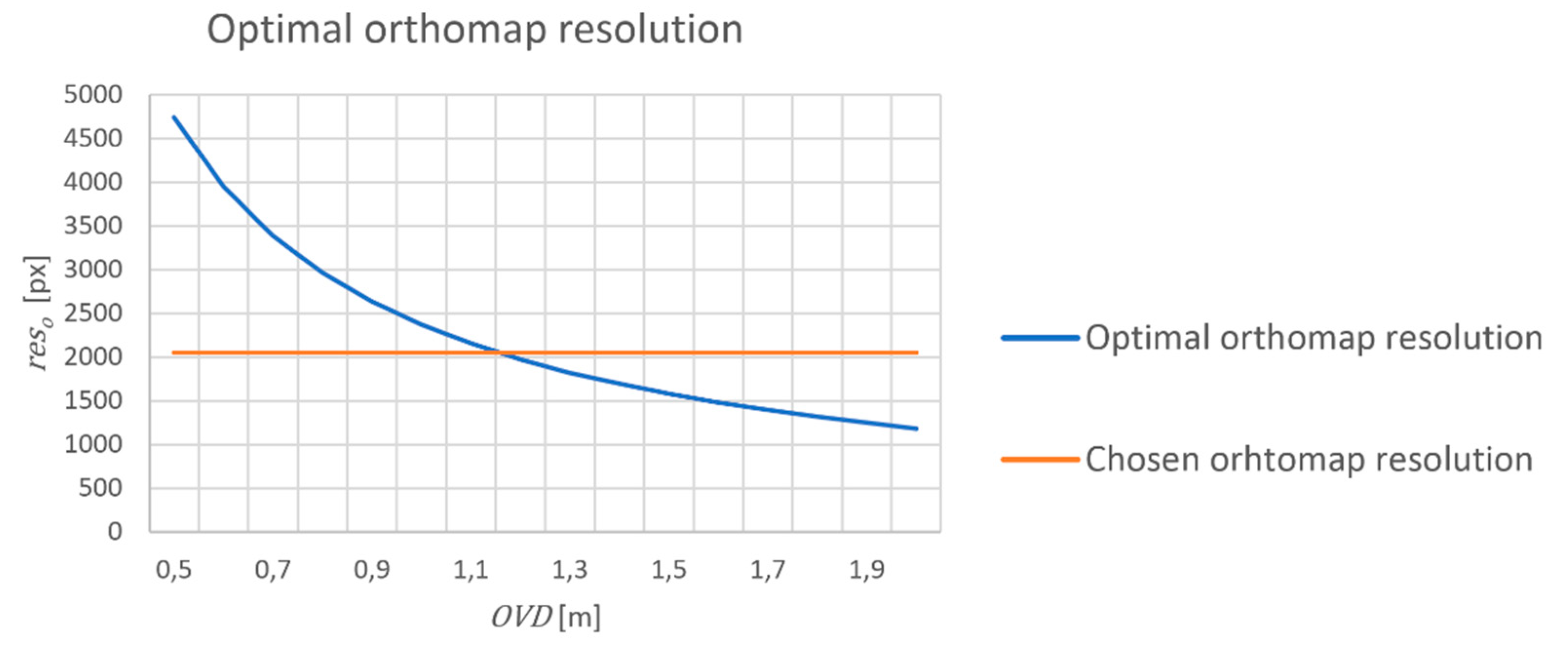
Depending on the type of interior, a user can be interested in bigger or smaller details. The optimal orthomap resolution must be computed depending on the assumed average distance between the camera and observed wall [we call it later the optimal viewing distance (OVD)]. In our tests, the application smoothly works from approximately 50% to 200% of the OVD. In our case, we set this parameter to 1 m. Desired orthomap resolution depends on OVD, camera resolution, its FOV and the real-world size of the interior.
From
Figure 6, we obtain:
where
indicates the camera field of view (FOV),
d is distance to the wall, and
x denotes the observed fragment dimension.
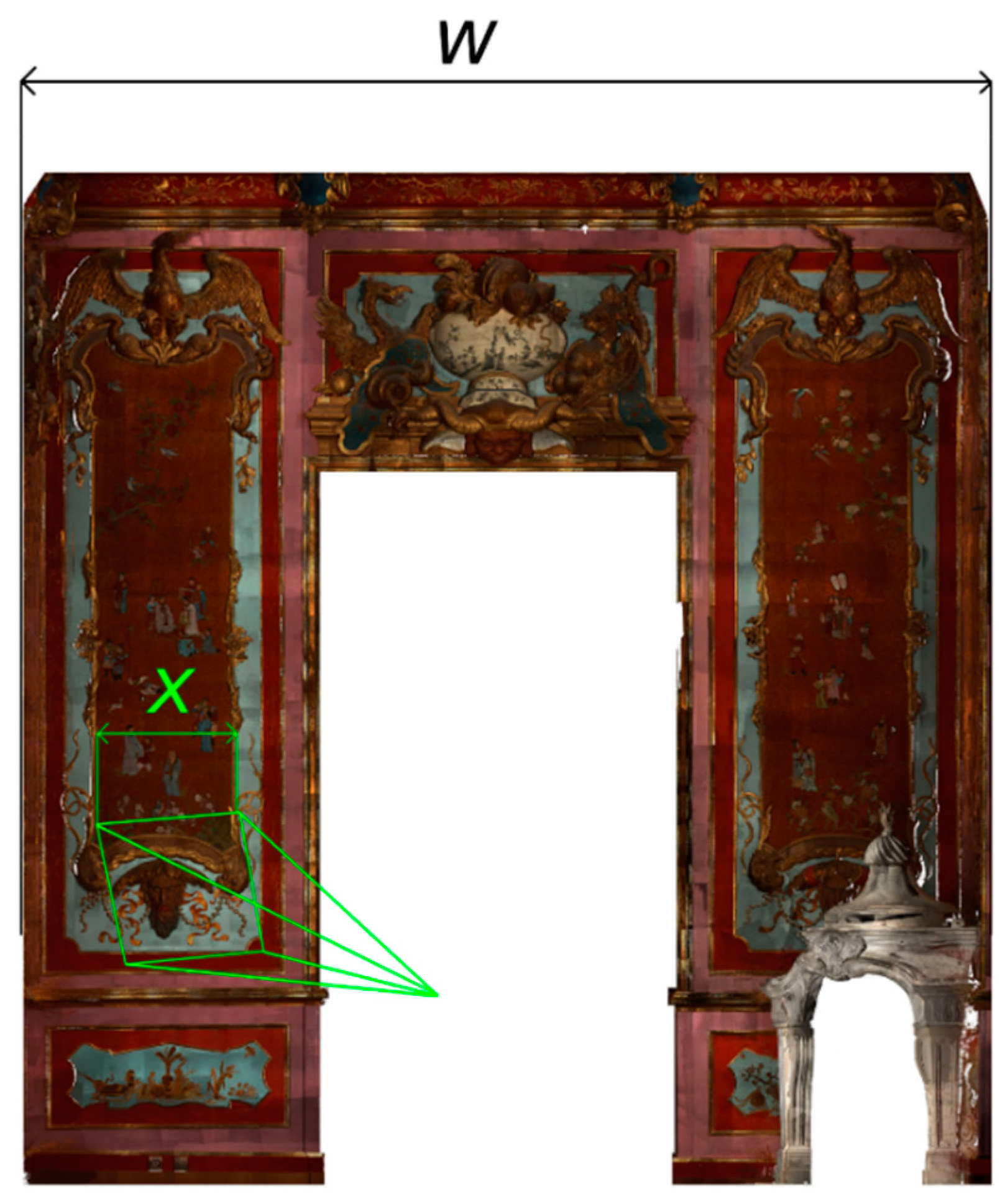
We want to maintain the scales of the keypoints as closely as possible. Thus, we intend to keep the ratio between camera resolution
resc (in pixels) and real-world dimension of observed fragment
x (in meters) equal to the ratio between orthomap resolution
reso (in pixels) and real-world dimension of the interior
w (in meters) (
Figure 7).
From Equations (2) and (3), we obtain:
Therefore, we propose equation (4) to compute the desired resolution. If we substitute our values, namely,
= 78°, which is the FOV of a Logitech B910 camera,
resc = 640 pixels, and
w = 6 m, we can draw a plot of
d against
reso (
Figure 8). In our case, we set OVD to 1 m, which allows the application mentioned in
Section 3 to run smoothly from approximately 0.5 to 2 m. Therefore, we decide to render orthomaps with a 2048-px resolution because it has the closest power of two to the chosen OVD (1 m).
The model distinctiveness strongly depends on the quality of the renders. The lesser the noise in the rendered image is, the more reliable and stable are the keypoints. Therefore, we decide to render the orthomaps using 4x antialiasing. We render them with four times bigger resolution and downscale them four times using bicubic interpolation to reduce the noise (
Figure 9). A detailed review of the different point cloud rendering methods with focus on descriptor extraction can be found in [
28]. As the paper suggests, we do not need splatting because our data is dense enough to render the point cloud without gaps, even with resolution four times higher in each dimension.
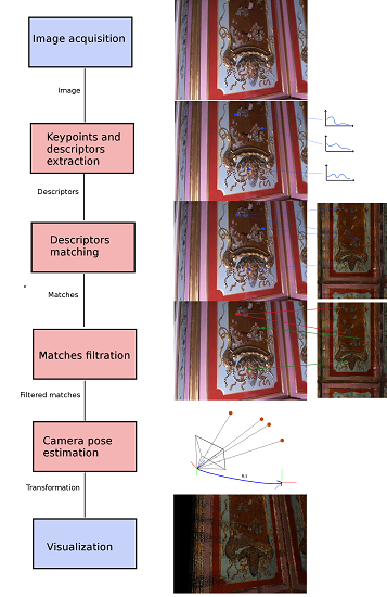
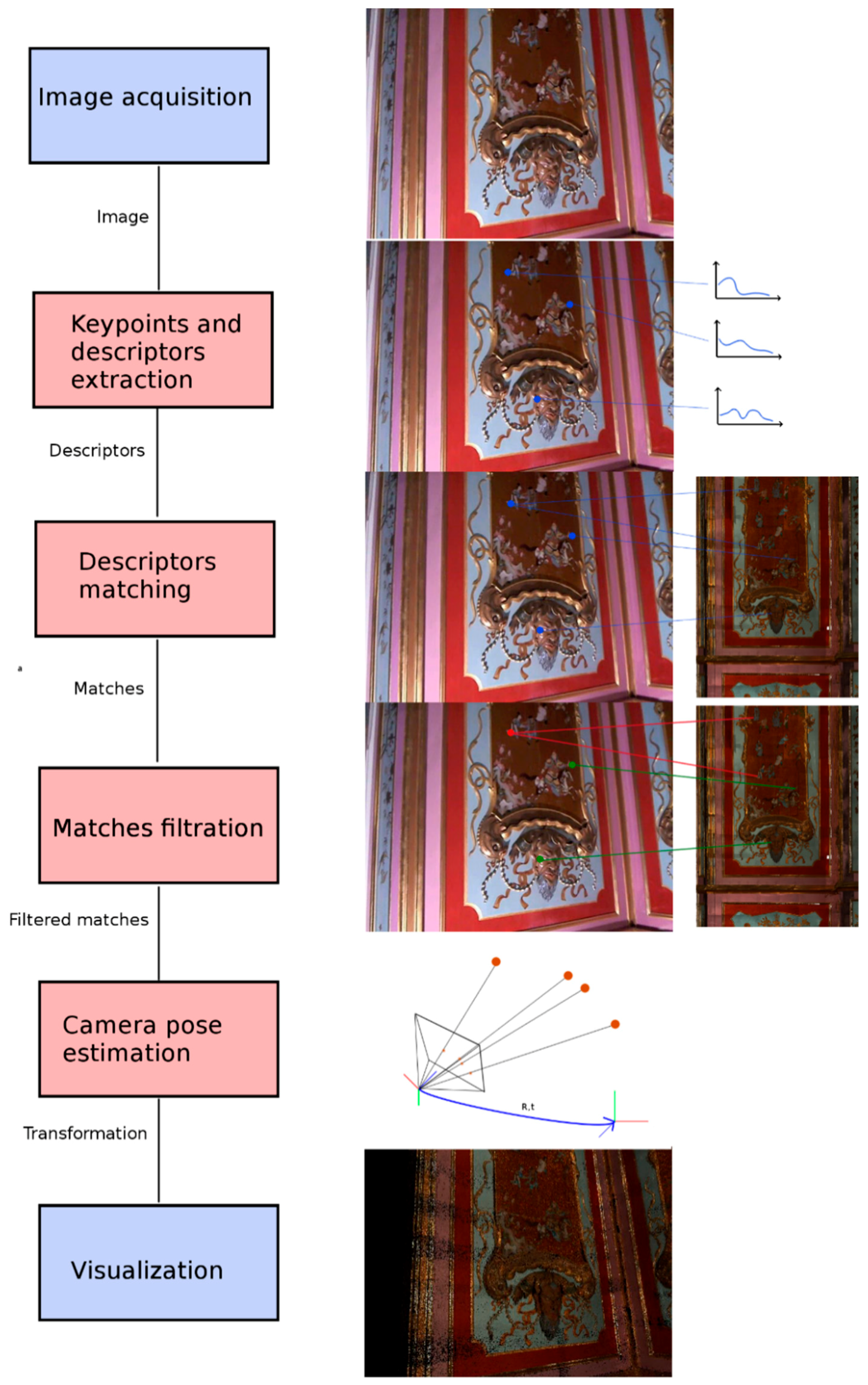
Our runtime diagram (
Figure 10) is similar to the state-of-the-art solutions. For every frame captured by the camera, we extract the keypoints and compute the descriptors. Because our model is very sparse (a few thousand keypoints), we can very effectively match it using a brute-force method on the GPU. We are aware that more methods are available to much more effectively match the descriptors on a CPU [
29], but matching on the GPU allows us to avoid costly data transfer between the descriptors extracted on the GPU and matches on the CPU side. Later, the matched keypoints are filtered using the ratio test proposed by Lowe [
13]. Then, the camera pose is computed using the EPnP (Efficient Perspective-n-Point) method [
30] supported by RANSAC (RANdom SAmple Consensus) sampling in which the P3P algorithm [
31] is used. The minimum required number of correspondences is 4, but we reject all the estimations that have less than 7 inliers to ensure that the camera pose is estimated correctly. The camera pose is then transferred to the visualization module. We take advantage of the fact that the camera is tracked inside a room; thus, if the computed camera pose is outside it, we reject the pose and do not send it to the visualization module. If the frame is rejected, the previous frame is rendered. We separately compute the camera pose in each frame and later smooth the camera trajectory using Gaussian filtration [
32] to reduce jitter in the camera movement.
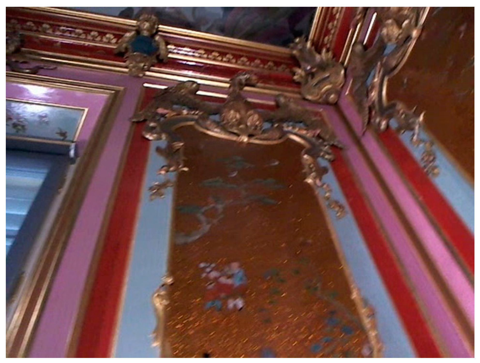
Because our approach relies on orthomaps generated parallel to the walls, processing of the frames with high angular difference from this direction could be challenging. This problem in descriptor matching is called angular invariance. Standard wide-baseline descriptors such as SIFT or SURF (Speeded Up Robust Features) [
33] have limited angular invariance of up to 30° [
34]. Thus, a very low number of correct matches (if any) are present if the angle between the camera axis and normal to the wall is large. This problem is clearly apparent when the ceiling of the room is very high and the user is looking at the elements located just under the ceiling (
Figure 11). To overcome this type of problems, the ASIFT (Affine SIFT) [
35] algorithm may be used, but the computational complexity is much too high for a real-time application. We differently deal with this problem by dividing the interiors into two main categories based on the ceiling altitude.
The average altitude in which the details located just under the ceiling do not require extreme viewing angle and camera tracking is based on the walls.
High ceiling in which the problem described above may occur. To overcome this problem, we exploit the fact that the ceiling may also have a rich texture (for instance, it may be covered by frescoes). We rotate the physical camera to point up to the ceiling so that it is always nearly parallel to the camera sensor plane. We estimate the camera position based on the ceiling and rotate it by 90° to visualize the view in front of the user. This solution also reduces the computational complexity by decreasing the necessary orthomaps from one per wall to one from the ceiling. However, this approach does not allow the user to view the ceiling. If the view of the ceiling is also important, we can render additional orthomaps for the walls and track the ceiling using the planar walls. In this case, the performance gain mentioned earlier is no longer available.
5. Results
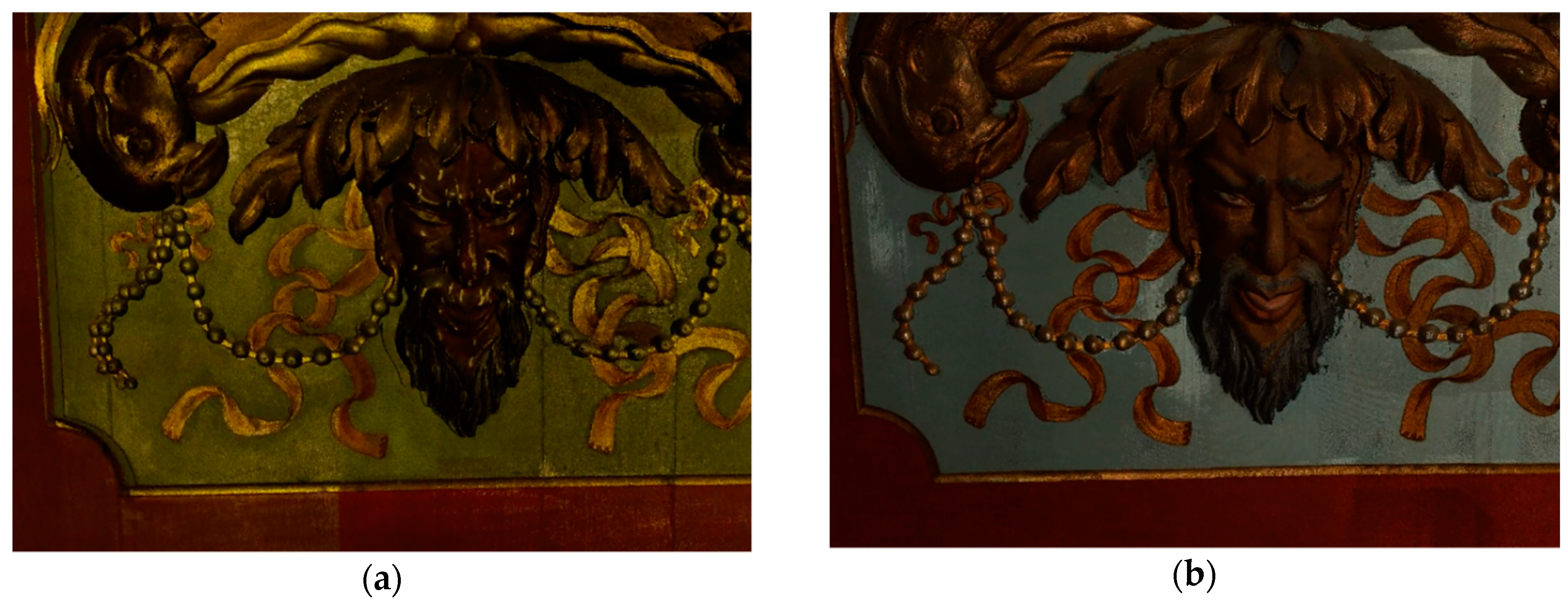
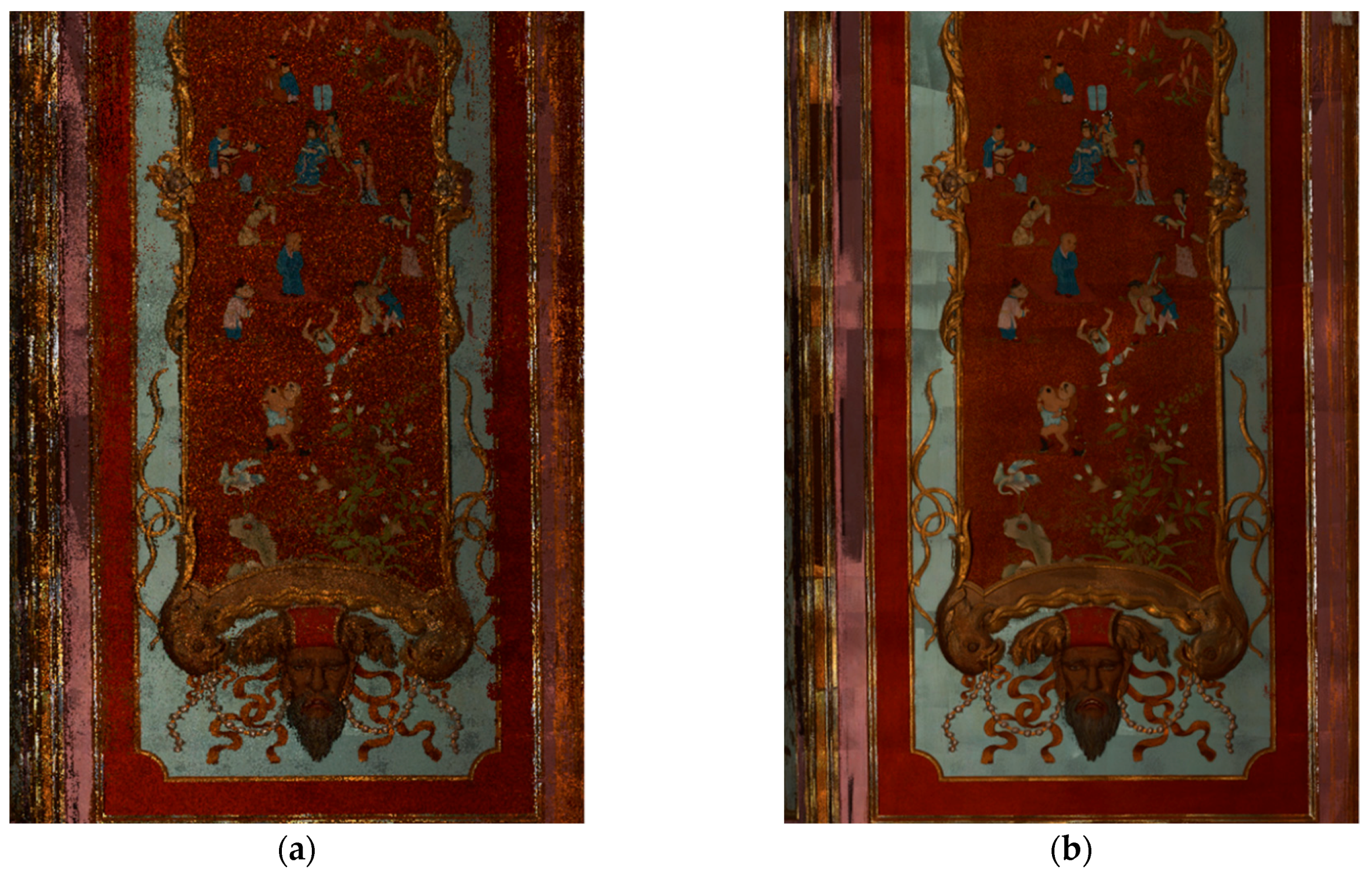
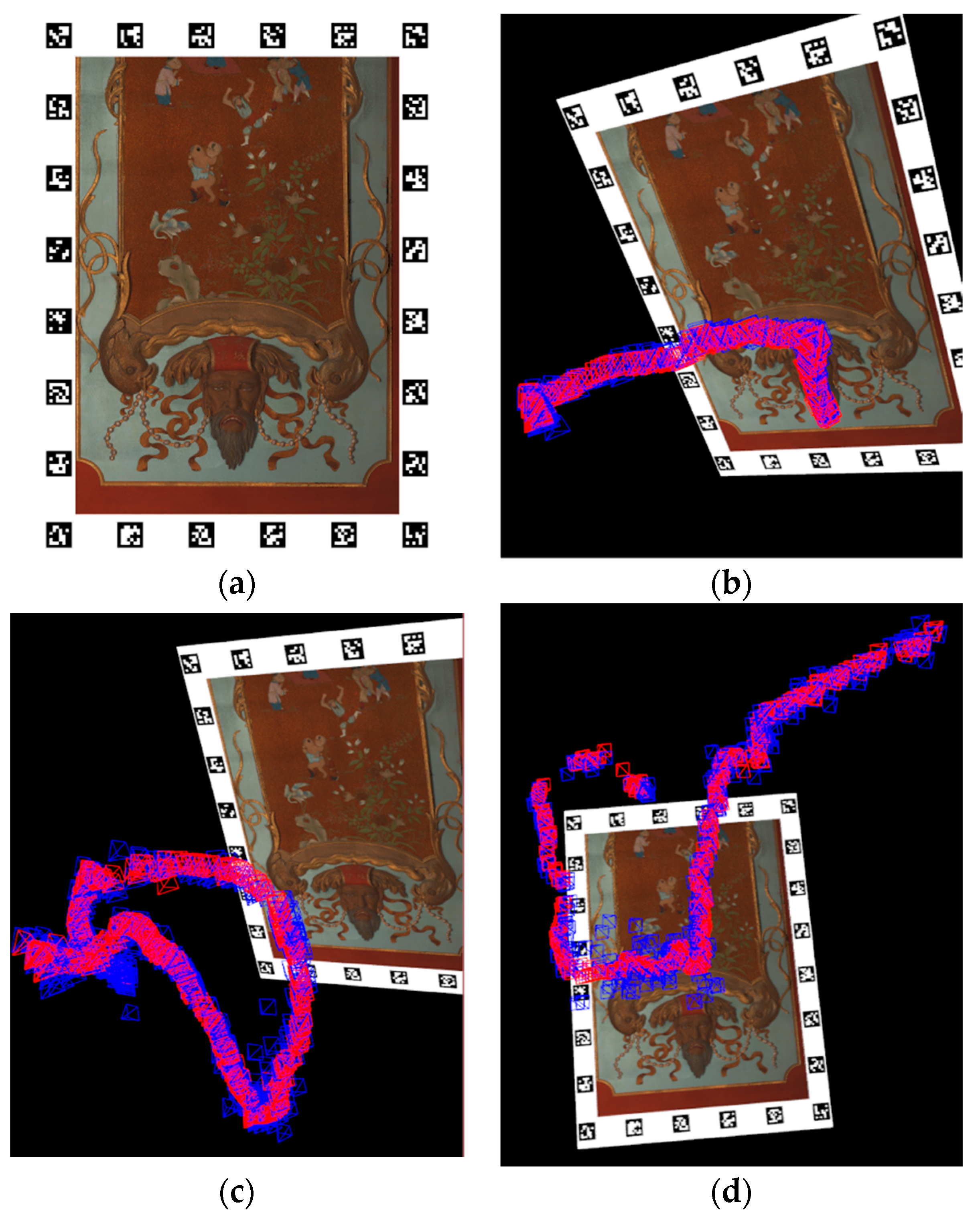
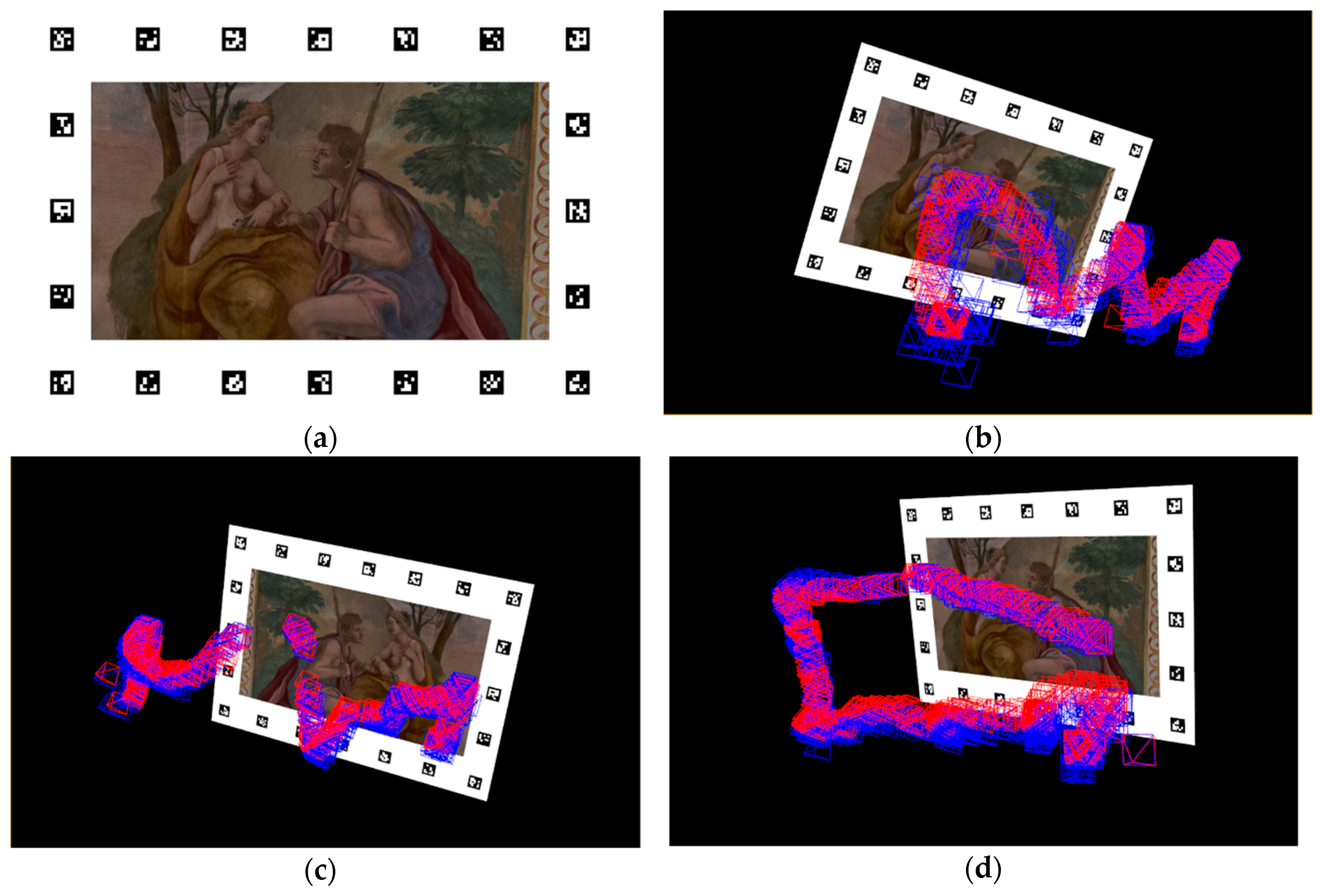
To evaluate the accuracy of the proposed approach, we tested it on two printed posters: on a real-size fragment of a scanned Chinese Cabinet (
Figure 12a) and actual size of the Al Fresco Cabinet (
Figure 13a). Both posters are surrounded by ARUCO [
36] fiducial markers. We recorded six different sequences that simulated the user behavior in front of the posters. In each frame, we estimated the camera pose twice, i.e., using keypoints from the poster and the corners of the extracted ARUCO markers. Both camera poses were then compared to evaluate the accuracy of our method. We considered the camera pose estimated from the ARUCO markers as our ground truth.
Figure 12b–d and
Figure 13b–d show the estimated camera trajectories in each sequence. The quantitative results are listed in
Table 2 and
Table 3. To measure the translation error, we calculated the Euclidean distance between the estimated camera poses from both methods and divided it by the L2 norm of the camera position estimated by ARUCO (Equation (5)).
where:
et—translation error
x1, y1, z1—coordinates of the ground-truth camera position
x2, y2, z2—coordinates of the computed camera position
We decided to normalize the translation error using the Euclidean distance from the marker to the camera because if the ratio between the error and distance remains the same, the camera image would also stay the same, regardless of the distance to the marker. To estimate the rotation error, we first converted the rotation matrices into quaternions and then computed the angle difference between them. We considered the angle obtained from ARUCO as the ground truth. Let us define two quaternions (
q1 and
q2) to represent the camera rotations from both methods.
Finally, let us compute the rotation error in radians as:
To examine the quality of the pose-estimation algorithm used in CATCHA, we decided to use statistical analysis. In each sequence, we calculated the four quartiles of the errors (Q1–Q4) and computed the interquartile range (
IQR) of our errors to determine how many pose estimations we could consider as gross errors.
To determine
IQR, we computed both the upper (
UF) and lower (
LF) fences with
k = 1.5 and marked the pose estimation errors that exceeded the upper limit as gross errors.
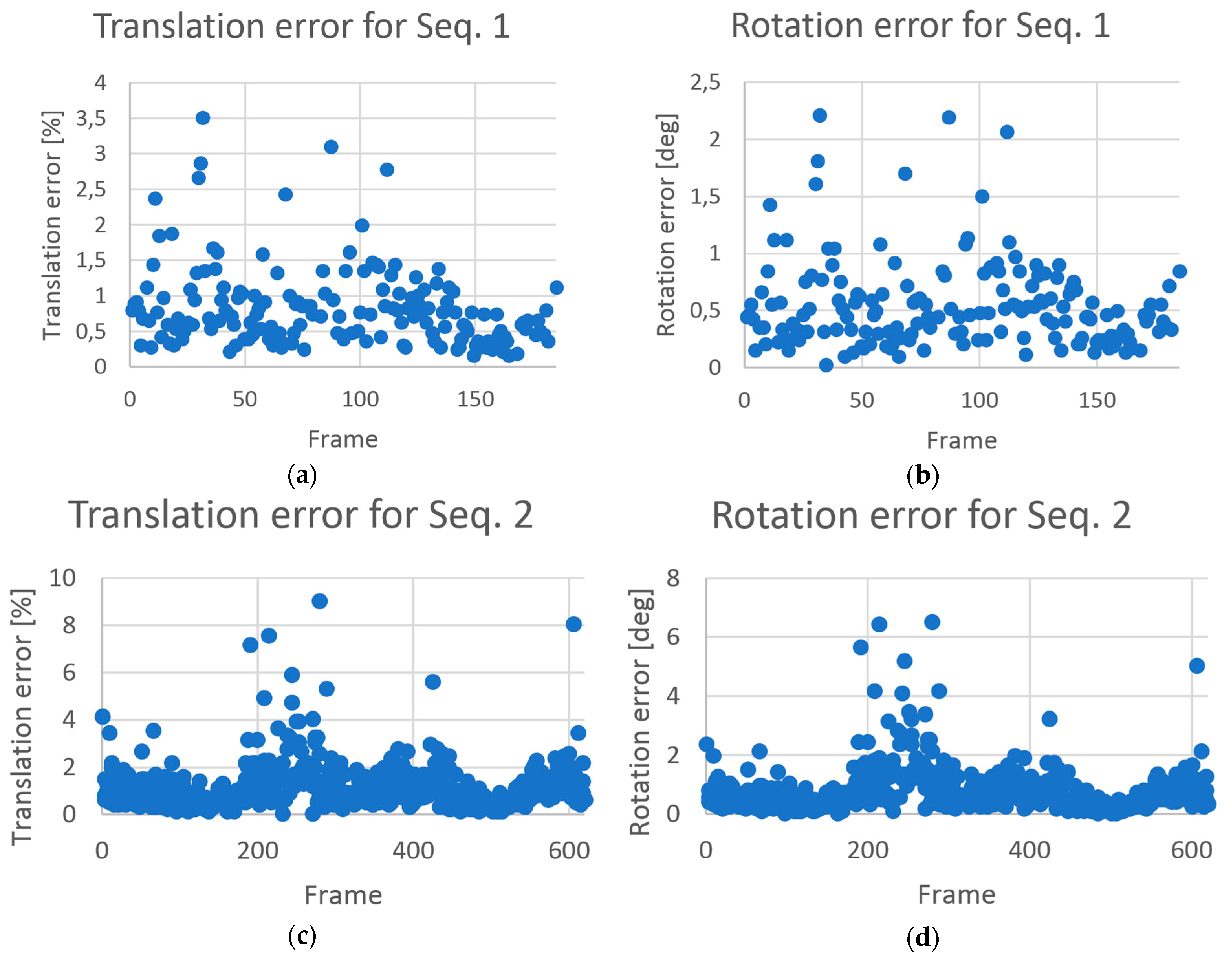
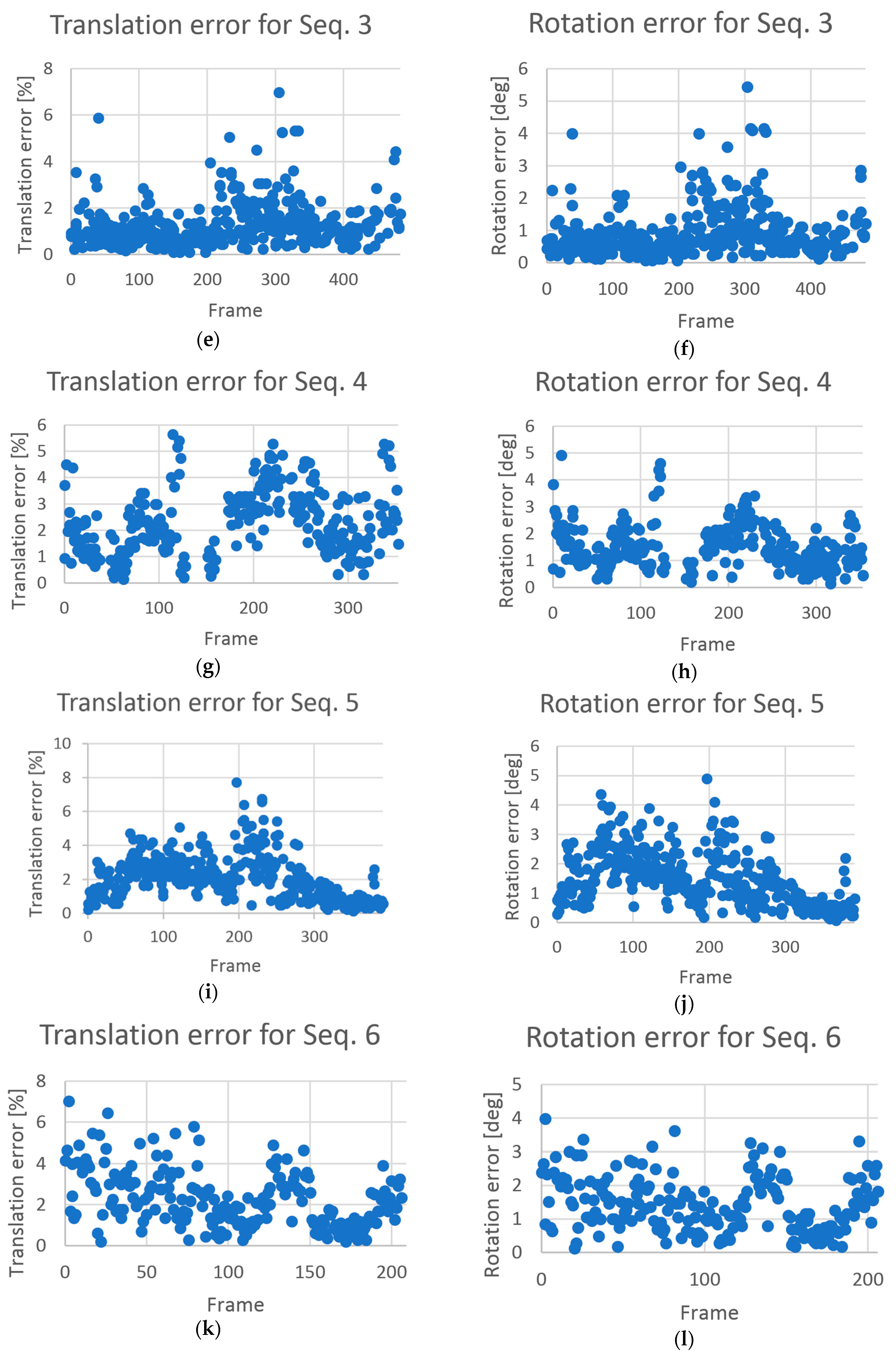
The mean error was below 2.5% in the translation, and it was below 1.5° in the rotation. The error values in each sequence are shown in
Figure 14. In each case, the level of outliers was approximately 5% for the King’s Chinese Cabinet and approximately 1% for the Al Fresco Cabinet. We note that the erroneous single-pose estimations were rejected and filtered using the visualization module so as not to affect the quality of the user experience. In our test procedure, we skipped the frames where only the markers in one row or one column were visible to avoid a situation where the reference pose was computed with a high rotation error.
With respect to the application performance in the museum, by implementing the setup mentioned in
Section 3, we achieved a mean frame rate of over 15 Hz directly using the SIFT descriptors on a mobile device. The mean frame rate increases up to 40 Hz using remote processing. This value is sufficient for smooth AR experience because many cameras on commercial devices and webcams have a maximum frame rate of up to 30 Hz.
6. Discussion
Cultural heritage objects are more or less under strict protection, and their limitations must be taken into consideration while designing AR solutions. The King’s Chinese Cabinet is an example of an interior under a very strict protection because of the very fragile pigments on the walls. The paintings may be damaged if illuminated by an infrared or ultraviolet light. In addition, the maximum permissible level of visible light is limited and the room is protected from any illumination sources, including sunlight. The presented restrictions forbid the use of RGBD cameras that emit infrared light. In contrast to the solutions in which light can be fully adjusted, such as those in shopping galleries, we are forced to limit the amount of light. To overcome the problem of darkness in the Cabinet, we could increase the exposure time of the camera or increase the gain. The former results in motion blur, and the latter increases noise. We decided to adjust the gain of the camera, but this also decreased the quality of the extracted and matched keypoints. We believe that this decision may have influenced the results.
Compared with most of the state-of-the-art approaches that depend on the SfM or DP models and images used to build them, CATCHA can be used on any textured point cloud without prior knowledge of its origin or the data used to construct it. In addition, the developed method can be used on point clouds built using any method, including SfM or DP. This factor indicates that CATCHA is substantially more versatile than many existing approaches. CATCHA is obviously limited to interiors with rich matte textures on the walls because its camera pose estimation algorithm relies on the keypoints extracted from the images. Line-based approach may be used if no textures are available or the surfaces are very glossy. CATCHA builds model from orthomaps that can be rendered from any model, regardless of its registration method and works well with interiors with perpendicular walls and ceilings. With regard to more sophisticated interior geometry (e.g., dome viewed from the inside), a much higher number of orthomaps may be required to cover the entire geometry and possible viewing angles. In this case, the model size and matching time increases. For larger models, more sophisticated matching strategies should be adopted. For those cases, the
k-means-based descriptor matching, proposed by Nister and Stewenius [
29], or matching using only a part of the original model based on the previous frames with a region-growing may be used.
Because CATCHA relies on a scanned 3D model of the tracked interior, if a significant change occurs in the interior’s appearance between the current state and the registered state (e.g. additional furniture), the 3D model has to be updated. Minor changes can be handled effectively, either in the matches-filtration step or by the RANSAC camera pose estimation algorithm. In the first case, unknown points should fail the ratio test due to a high distance to known points from the orthomap, and the ratio between the first and second nearest point would be close to 1. One of the possible solutions would be to integrate a SLAM-based tracking module to detect potential significant changes in model geometry or to track the model in areas that are poorly covered on the renders.
We partially overcome the problem of high-viewing angles by dividing the interiors into two groups, as mentioned in the previous section. However, this solution does not ensure that a camera pose would be established, regardless of the viewing angle. The first approach is limited by the viewing angle (
Figure 11), and the second approach is limited by the fact that the camera has to point in the direction of the ceiling. In the Cabinet example, where the ceiling is approximately 6 m high, we examined both strategies mentioned in
Section 3. The second strategy resulted in better user experience because the ceiling was always nearly parallel to the camera sensor plane. Additionally, keypoints were extracted and more robustly matched. Further, in the case of this particular interior, the walls contain much gilding that caused reflections in the camera frame, which, in combination with high viewing angles, resulted in less stable keypoints.
Because CATCHA uses RANSAC to eliminate outliers in the matches between the model and current camera frame, its performance depends on the number of points after filtration of the camera image. If this number is extraordinarily high, the frame rate may significantly drop. To eliminate this problem, different outlier rejection strategies such as that in [
37] may be applied. The problem of a high outlier ratio can be partially handled by higher orthomap quality because the lesser the noise is, the more accurate is the keypoint matching and thus the fewer are the outliers. The experimental results presented in the previous section showed that the shapes of the translation and rotation errors (
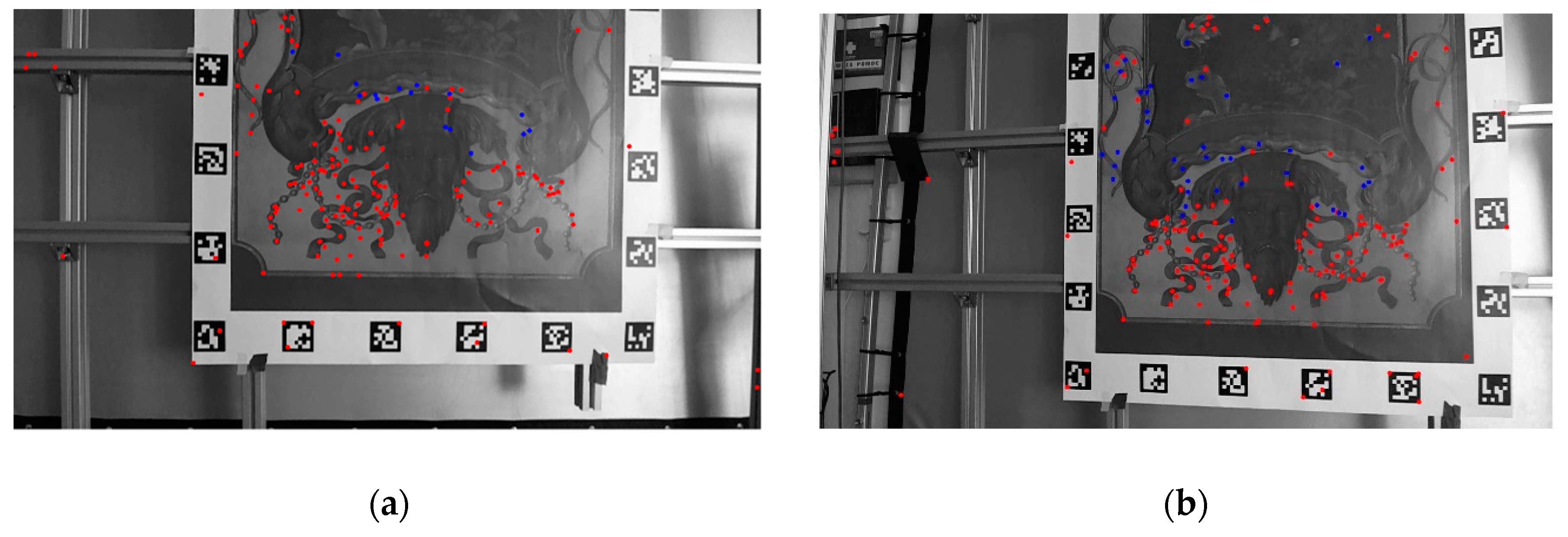
Figure 14) were almost identical because translation and rotation were simultaneously estimated and one compensated the other. The mean and median error values obtained in the King’s Chinese Cabinet were much lower than those obtained in the Al Fresco Cabinet because the quality of the registered texture of the latter model was lower. Despite this condition, the outlier ratios were higher in the King’s Chinese Cabinet because much gilding and many other shiny surfaces were present that could cause unstable keypoints. The reason for the high error values on certain frames was that the matched keypoints populated only part of the image (
Figure 15). Because of the non-uniform distribution of points used as an input to the PnP algorithm, the solution may fall in the local minimum, instead of the global minimum. The error distribution does not depend on a specific camera layout but rather on the configuration of matched keypoints found in the image. Single-error camera-pose estimations did not affect the animation quality because the camera path was smoothed using Gaussian filtration. In both analyzed interiors, the outlier ratios and error values were sufficiently low to allow smooth and precise visualization of the details.
Beside the developed AR application allows the user to visually compare two states of the interior, the presented algorithm may be a base of many potential AR applications for professionals such as interactive model analysis (e.g. real-time curvature visualization and multispectral data mapping), presentations of interior design or interactive annotations for cultural heritage restorers. Ordinary visitors may be interested in simple augmentation of the interior with digital content, such as virtual guides who could walk around the interior and tell the story of the location. That would make the sightseeing more immersive.


