As-Built BIM for a Fifteenth-Century Chinese Brick Structure at Various LoDs


1
School of Architecture, Nanjing Tech University, Nanjing 211800, China
2
Nanjing City-Town Architecture Design and Consultants Co., Ltd., Nanjing 210036, China
3
School of Architecture, Southeast University, Nanjing 210096, China
4
School of Design, Shanghai Jiao Tong University, Shanghai 200030, China
*
Author to whom correspondence should be addressed.
ISPRS Int. J. Geo-Inf. 2019, 8(12), 577; https://0-doi-org.brum.beds.ac.uk/10.3390/ijgi8120577
Submission received: 23 October 2019
/
Revised: 21 November 2019
/
Accepted: 10 December 2019
/
Published: 11 December 2019
(This article belongs to the Special Issue BIM for Cultural Heritage (HBIM))
Abstract
:Building information modeling (BIM) has received significant research attention in the field of built heritage. As-built BIM refers to a BIM representation of the “as-is” conditions of built heritage at the time of a survey. Determining the level of development (LoD) is crucial for as-built BIM owing to its relevance to model effects and modeling efforts. This study addresses this issue from the viewpoint of a brick structure based on a case study of a fifteenth-century ruin in Nanjing, China. Three LoDs are proposed based on the combined use of a commercial platform and auxiliary tools: A host model linked with raster images composed using orthoimage and relief maps (LoD 1), an as-built volume with semantic skins (LoD 2), and a brick-by-brick model with custom industry foundation class parameters at local areas (LoD 3). The results reveal that LoD 1 caters to an efficient web-based workflow for brick-damage annotations; as-built dimensions can be extracted from LoD 2; and LoD 3 enables attributes, such as damage types, to be attached at the brick level. In future studies, the detection of brick shapes is expected to automate the process of as-built surface mapping.
1. Introduction
Bricks are among the oldest building materials, and brick-built heritage structures are widely distributed globally [1]. Recent developments in optical sensors and computer vision (CV) algorithms have made it easier to measure brick structures. Terrestrial laser scanning (TLS) and photogrammetry are widely used for these measurements [2,3]. A combination of these methods can be used to achieve high-resolution (HR) documentation with high geometrical accuracy (mm level) and chromatic fidelity (24-bit color space). However, certain surveyed spaces are too narrow to use TLS and photogrammetry; hence, technologies such as mobile scanning [4] and spherical cameras [5] are being developed. Even though the accuracies of these methods are lower than those of previous methods, they ensure rapid in situ measurements and robust scene transition in narrow spaces, as the devices can be operated while walking.
Graphically representing measurement results is considerably more challenging compared to measurements. The metric survey of historic buildings is considered a “measured” and “drawn” process [6]. Owing to the advances of measurement technologies and three-dimensional (3D) models coupled with databases, drawing, in a broader sense, is expected to be the medium that links measurements and heritage studies and caters to various demands. Hence, graphical representation involves data segmentation, database establishment and data transfer. Existing solutions vary depending on the purposes of the survey [7,8,9].
The direct output of an optical measurement includes a point cloud and a mesh surface. Even though these outputs can be highly accurate, dense and texture-rich, they are not semantically structured and do not possess information (material, physical properties, etc.) other than geometry and color. However, a semantically-rich 3D model is highly favorable for numerous conservation-oriented applications of masonry structures, such as characterizing surface damage [10] and assessing overall structural safety [11,12,13]. It is challenging to convert raw measurement data and meet the demands of data consumers (architects, engineers, archeologists, etc.) because the required modeling effort increases with the amount of as-built information. This problem is ubiquitous to built heritage surveys [14,15], but requires special attention when a masonry structure is the survey target. Surface mappings (characterizing damage, provenance and dating) are mandatory for any conservation or restoration interventions that affect facades [16]. However, extra effort (segmentation and metadata enrichment) is required because facades are composed of thousands of masonry units.
1.1. Existing Approaches Based on CAD and GIS
A conventional approach for representing a brick-masonry facade is to overlap raster images with vector layers [17]. Raster images can be obtained from rectified photography [18] or orthophotos generated using photogrammetry [19], while vectors are manually drawn by mapping the former in computer-aided design (CAD) programs. CV algorithms segment masonry units using point clouds and images [20,21,22]. However, manual operations may still be necessary given the complexity of the masonry surfaces that have experienced damages and alternations. CAD facilitates vector visualization with line types and hatched overlays. This approach is applicable to two-dimensional (2D) surfaces and volumes. It provides precise edge segmentation along with surface information on a texture. However, the metadata on masonry units are limited to geometry, and nongraphical data are not included. Hence, CAD-based representation allows for easy-to-use drawing and intuitive visualization but not data management and further simulations.
The use of a geographical information system (GIS) addresses the limitations of CAD in data management and graphical analysis. Raster data can be processed using the in-built functions of GIS platforms, including segmentation, vectorization and comparison. Masonry units are represented by shapefiles that can be labeled, sorted and filtered according to user-defined logic (provenance, dating, damage patterns, etc.). These functions help users create thematic maps [23] and share them via GIS-extended web browsers [24]. However, GIS is inherently oriented toward representing geographical elements, and not architectural components and their semantic data. Even though 3D visualization is achievable [25], the use of GIS to represent masonry structures is limited to 2D graphical applications, instead of applications that require 3D volumes and architectural semantics, such as drawing production and structural analysis.
1.2. BIM as a New Solution
Building information modeling (BIM) is a component-based modeling environment that is semantically structured [26]. Even though BIM was developed for the architecture, engineering and construction (AEC) industry, historic BIM (HBIM) attracted research interest from the field of built heritage. It is considered a potential platform to bridge the gap between advanced measurements and various conservation-oriented applications [27,28]. As-built BIM refers to a BIM representation of the “as-is” state of built heritage at the time of a survey [29]. It is oriented toward representing the damages, decays, missing parts and other imperfect conditions using advanced measurement technologies. As BIM is not inherently oriented toward modeling and managing as-built data, fundamental issues should be addressed with the characteristics of historic brick structures.
1.2.1. Level of Developments
An effective strategy of as-built BIM is the establishment of an appropriate level of development (LoD; also known as level of detail), with reference to the standard BIM procedures within the AEC industry [30]. LoD is generally considered as a grading system that defines the complexity of a model, even though the definition may vary in different standards. For example, LoD 100–500 was employed by BIMForum to define the LoD from element representation to field verification [31], while a grade of LoD 1 to 6 was adopted by the UK standard for referring to the level of detail [32].
In the field of built heritage, a few studies have refined the concept of LoD with emphasis on the “survey to BIM” process by defining the level of accuracy, the level of knowledge, and the grade of generation [8,16,33]. LoD F and G are adopted by the Italian standard to define the grades of the as-built conditions of architectural heritage [34]. English BIM guidelines adjusted the above-mentioned UK standard of LoD to built heritage [35].
The correlations between LoD and model effects are positive. As higher LoDs exert a stronger positive effect on decision making for new buildings, a highly developed BIM model better supports structural simulation [36], restoration management [33] and in situ maintenance [37].
Challenges arise in the case of historical brick structures. For example, a brick wall at LoD 400 (after BIMForum’s standard) in the AEC industry literally requires individual masonry-unit division [31]. This LoD has proved useful to the stakeholders of masonry construction, such as architects, structural engineers, and mason contractors [38,39]. The modeling of brick units in BIM has encouraged technique studies on brickwork [40] and the high-resolution (HR) documentation of built heritage [41]. However, the semantic data in commercial BIM platforms (e.g., Autodesk Revit) are retained at the component level (e.g., a brick wall) rather than individual brick units. Is a brick-by-brick model with a large file size and void semantics required by architectural historians, archeologists, and restorers during the conservation process?
Thus, it is crucial to evaluate the roles that LoDs play in studying and conserving historical brick structures, including model effects (e.g., damage annotation, production of drawings and deformation analysis) and modeling efforts.
1.2.2. BIM Tools
Most current approaches of HBIM use commercial BIM platforms (e.g., Revit, ArchiCAD) or combine them with auxiliary tools, GIS methods and open-source software (OSS) tools [42].
Commercial BIM platforms contain parametric libraries and established workflows. However, they are inherently oriented toward the AEC industry instead of built heritage, particularly in as-built conditions. Problems arise in modeling nonstandard objects and customizing attributes (e.g., damage pattern, conventional materials). As noted by Diara and Rinaudo [43], compromises are prone to be made in survey projects owing to the limited customization options in commercial BIM platforms.
Various solutions have been proposed to customize the BIM representations of built heritage. Barazzetti proposed a method of creating parametric BIM components using nonuniform rational basis splines (NURBS) via the Rhino commercial software [14,44]. Garagnani employed the Revit application programming interface (API) to develop plug-ins for as-built modeling [15]. API was also adopted by Bruno for database customization in Revit [45]. Yang integrated a built-in visual programming tool of Revit (Dynamo) and an ontology semantic to provide components with accurate geometry and self-defined knowledge [46]. A system that combines BIM and GIS is a tendency. Data exchange between BIM and GIS has been enabled in the recent releases of commercial platforms (Revit model can be read in ArcGIS PRO 2.2) [47]. However, applying them to built heritage requires further study. OSS tools provide a high extent of customization through the utilization of database management systems, CAD platforms, and webservers. Studies on this topic are in progress [43,48].
In this study, we achieve low LoDs (LoD 200 and 300 after BIMForum) using the default operations of commercial BIM platforms considering reasonable modeling efforts, and adapt the BIM representations for surveying brick structures at a high LoD (LoD 400 after BIMForum, a brick-by-brick model) by utilizing OSS tools.
1.2.3. Format Issue
Industry foundation class (IFC) is a neutral data-exchange standard developed by “buildingSMART” to facilitate interoperability among BIM platforms in the AEC industry [49]. An IFC model is an assembly composed by a set of schemas, each corresponding to one IFC layer, such as IfcObject, which records objects characteristics and types [50]. In commercial BIM platforms such as Revit, semantics can be attached to a brick wall instead of individual brick units by default. OSS tools are available for addressing this issue by working with an IFC proxy. According to the definition provided by American Institute of Architects, an IFC proxy is intended to be a container for wrapping the objects that are defined by associated properties which may or may not have a geometric representation and placement in space [51]. For instance, VisualARQ, which is a plugin of Rhino, enables self-defined parameters to be read, modified, and filtered in BIM platforms via an IFC proxy. This tool is employed in this study to create semantic-rich brick units.
1.3. Brick Heritage of the Ming Dynasty
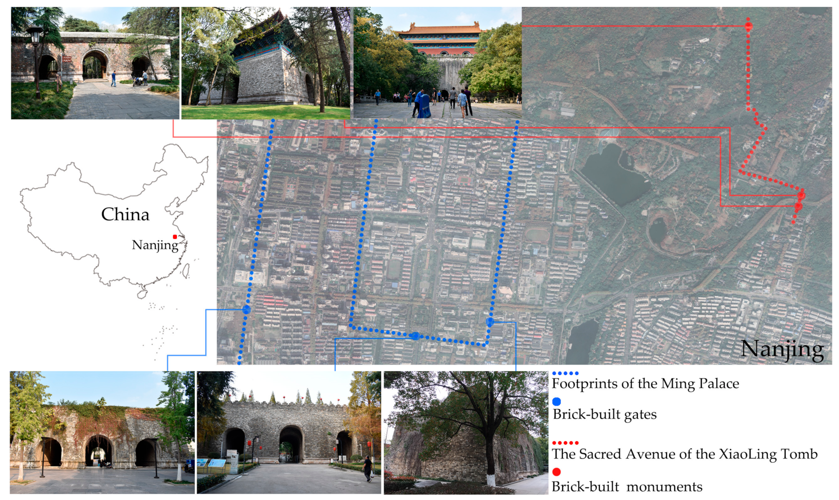
The Ming Dynasty (1368–1644 AD) witnessed the rise of brick structures in China. The Great Wall was extensively strengthened and rebuilt during this period for the third time in history [1], and most of the ruins observed today originated during this period. As the capital of the Ming empire before 1421 AD, Nanjing retains abundant brick-built ruins, including royal tombs, temples, civil infrastructures and city walls (Figure 1).
Even though the Ming Dynasty brick heritage sites have been under regular maintenance—a few of them have been designated as UNESCO World Heritage sites (as part of the Imperial Tombs of the Ming and Qing Dynasties) and a few have been placed on the tentative list (as part of the City Wall in the Ming and Qing Dynasties)—no metric survey at the brick level has been conducted on these structures yet. TLS has been employed in measurements, but drawings are delivered without sufficient details on brickwork and as-built conditions. The absence of as-built modeling methods at various LoDs is the bottleneck between measurement and conservation.
1.4. Study Purposes and Paper Structure
In contrast to existing studies on the development level of BIM, with relevant criteria such as the grades of knowledge, information and accuracy [8,33], this study is addressed to a certain type of built heritage (i.e., brick-built heritage structures from the Ming and Qing Dynasties of China). It focuses on exploring the model effects and modeling effort at various LoDs towards a BIM representation of the studied cases. In addition, the capabilities of commercial BIM platforms and auxiliary tools are studied with reference to the characteristics of historic brick structures from the viewpoint of modeling and data enrichment workflow.
The remainder of this paper is organized as follows: Section 2 outlines the study target and proposed methods. Section 3 presents the results obtained at each LoD. Section 4 analyzes the results from the viewpoint of potential applications, limitations and future work. Section 5 presents concluding remarks.
2. Materials and Methods
2.1. The Stele Tower and Optical Measurements
The Stele Tower is located at the Xiaoling Tomb, Nanjing, China (Figure 2). Zhu Yuanzhang (1328–1398 AD), who was the first emperor of the Ming Dynasty, and his wife Ma, are buried in the Xiaoling Tomb. Along with other imperial tombs built between 1368 and 1915 AD in Beijing Municipality, Hebei Province, Hubei Province and Liaoning Province of China, the Xiaoling Tomb constitutes the UNESCO World Heritage site “Imperial Tombs of the Ming and Qing Dynasties.” Buildings and stone carvings are scattered along the 2.6 km-long zigzag Sacred Avenue of the Xiaoling Tomb.
The Stele Tower is located 70 m to the north of the Big Golden Gate, which is the front gate of the outer wall of the Xiaoling Tomb. The tower was built to accommodate a stone stele engraved with the achievements of Zhu Yuanzhang (Figure 2a,b). It contains a square plane with a side length of 26.9 m. Brick walls with a height of 8.8 m are decorated with Sumeru Pedestals. A doorway spans a barrel vault on each side of the square plane (Figure 2c). The original timber skeleton above the brick walls was destroyed during a war in the nineteenth century, and a new one was built in 2013.
The bricks were laid with Dutch bond on the walls and stretcher bond on the vaults in general. The bricks have undergone alterations (Figure 2d) and damage caused by wars and natural forces (Figure 2e). However, an HR survey concentrating on the brick ruins has not been conducted thus far.
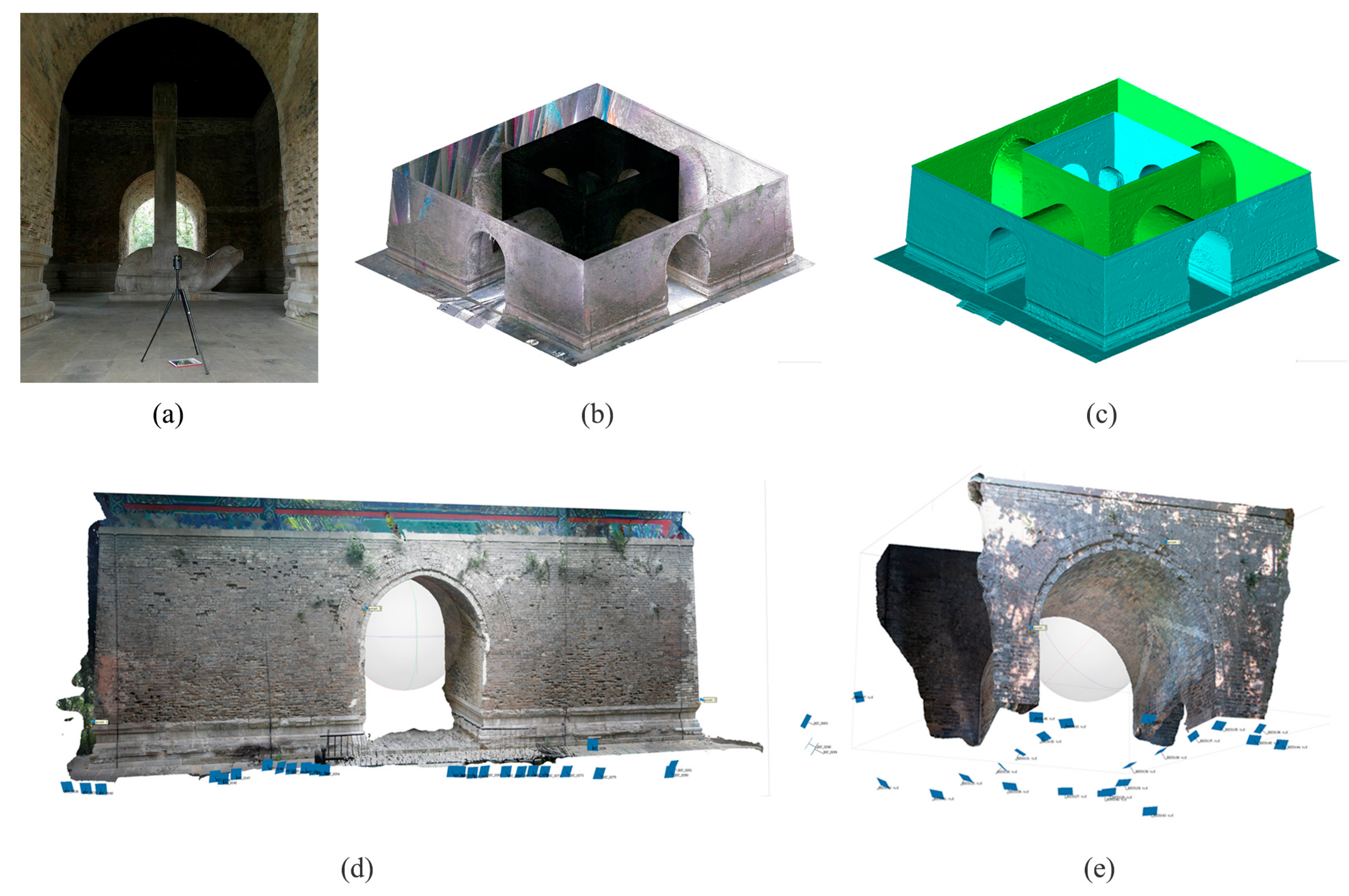
In our study, TLS and photogrammetry were employed when measuring the Stele Tower. In addition to accuracy, portability and efficiency were considered when conducting measurements because the site is frequently crowded with tourists. Leica BLK 360 was used to scan the entire building and generate a global mesh model from 21 separate scans (Figure 3a–c). The mean error of registration (based on natural features) was less than 3 mm. The segments of textured mesh surfaces were generated using photogrammetry, with the aim of documenting the chromatic information of crucial parts (Figure 3d,e). Images were obtained using hand-held cameras with convergent camera networks and automatically aligned using Agisoft PhotoScan. The generated mesh surfaces were approximately registered using the control points extracted from the TLS-derived model and finely registered in CloudCompare using an iterative closest points algorithm. Then, the TLS-derived point cloud was imported into the BIM environment (Autodesk Revit 2019 in this study), and the registered mesh models were imported into a visual programing environment (Rhino 6) as modeling reference.
2.2. Representing As-Built Information at Various LoDs
Instead of cloning the LoD standard of masonry components from the AEC industry, a different classification was defined in this study, considering the demands of as-built modeling and the characteristics of the study target. It consisted of three LoDs (LoD 1, 2 and 3) that represented the as-built information at the imagery level, component (region) level and brick level.
2.2.1. Host Model Linked with Raster Imageries (LoD 1)
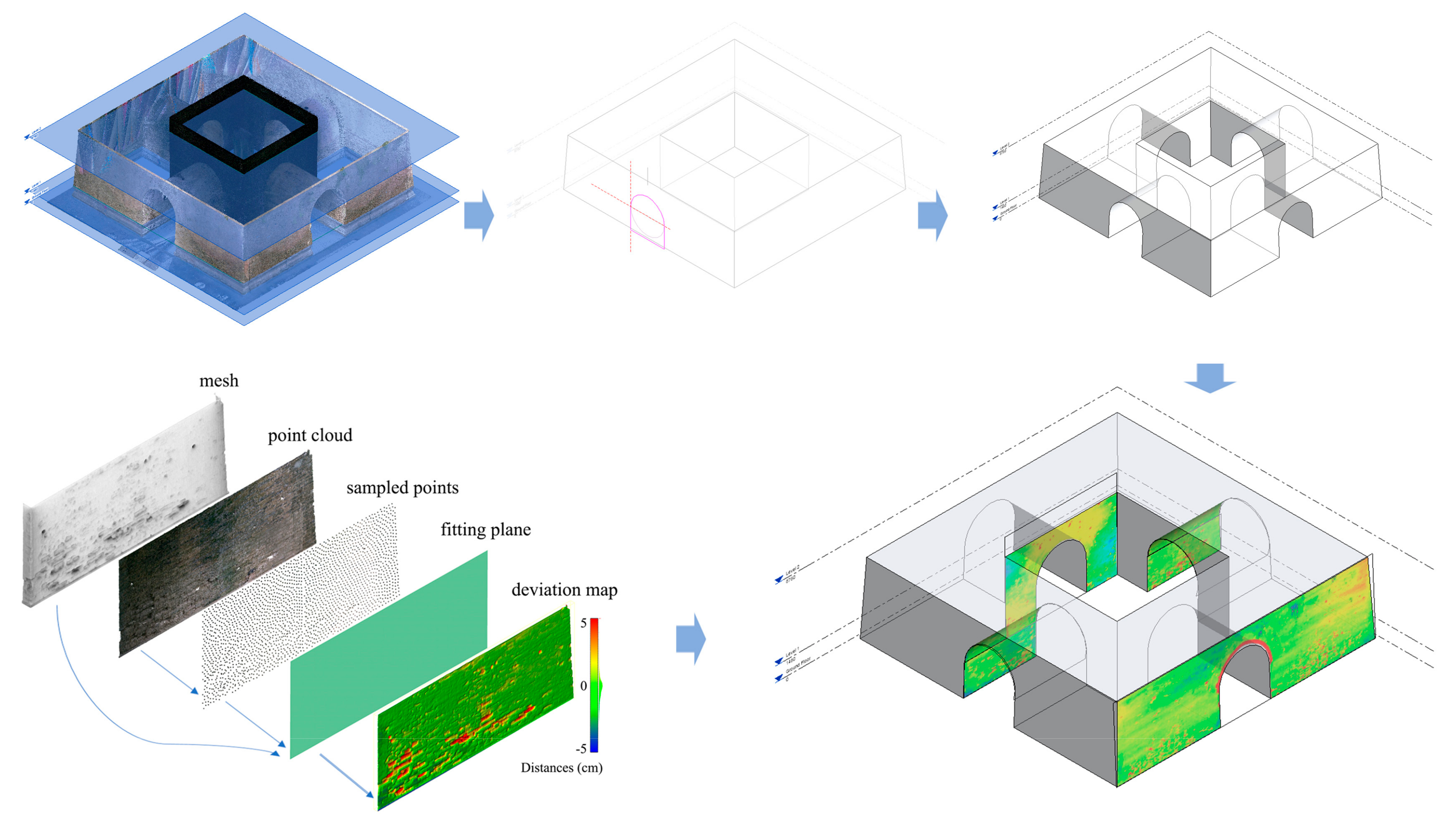
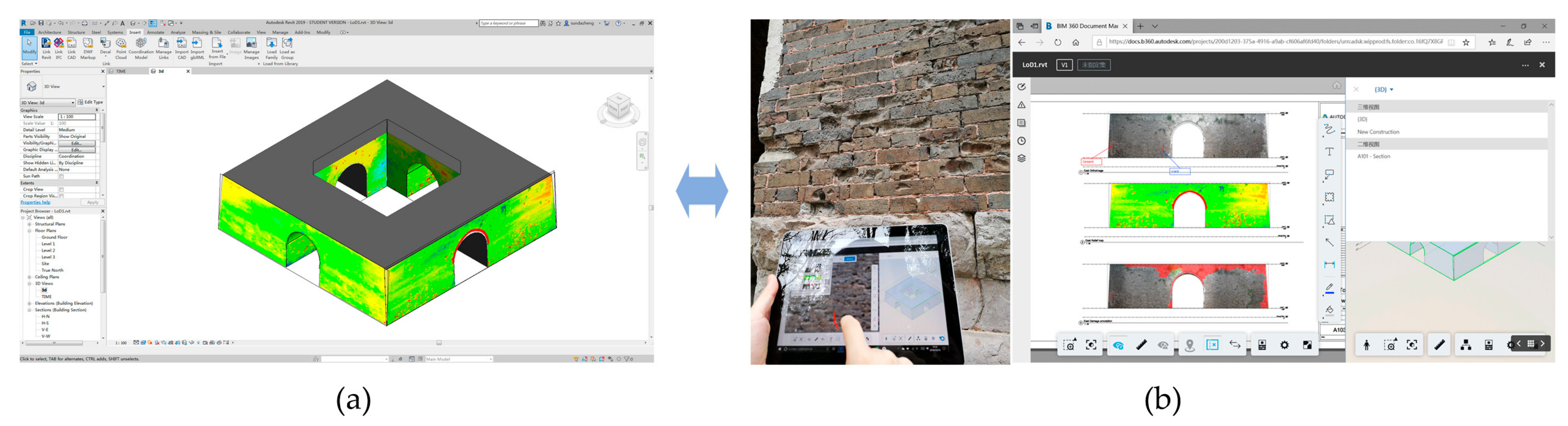
This LoD is oriented toward easing data sharing and in situ maintenance using portable devices. As-built information is expected to be delivered in an intuitive manner. We addressed this demand by creating a host model that enabled raster images with as-built information to be linked and visualized in associative elevation and section views (Figure 4).
The host model represented an ideal form (as-designed) without considering the as-built geometry. It was considered symmetrically composed of basic elements such as straight lines and semicircles. The point cloud was used to accommodate contours for 3D modeling, but the slight asymmetries and deformations of the as-built condition were neglected. The volume of the Stele Tower was generated by blending two rectangular contours at the ground floor level and top level. Four vaulted doorways were spanned using four void volumes to penetrate the solid volume. The above operations were created as a “mass” through “in-place component” in Revit.
The as-built raster imageries included orthoimages, generated with photogrammetry, and relief maps showing the depth information of brick surfaces such as holes and missing blocks. The relief map of each segment of a wall and a vault was colored according to the distances between the TLS-derived point cloud and its fitting plane. The latter was defined by interpolating the subsamples of each segment. The distances between the fitting plane and point cloud were computed using signed distances. The relief maps (.png format) were attached to the corresponding surfaces (via “decal” in Revit) along with orthoimages to provide intuitive as-built conditions and clues for annotations.
2.2.2. As-Built Volume with Semantic-Aware Skins (LoD 2)
A modeling process similar to that of LoD 1 was adopted, with two different operations (Figure 5):
- As-built geometry contours. The contours that generated mass volumes were obtained by manually mapping the point cloud with splines with high density. Over 20 control points were used to define a vault section, and three contours were used to generate 3D vaulted shapes by lofting the contours.
- Semantic-rich skins. Once the solid volume penetrated by vaulted passages was generated, each surface was converted to a component (wall family) using “wall by face” in Revit. This enabled the skins of the volume to retain the same parametric geometries (wall thickness) and semantic data (material layers) as those inherently established (system family) in Revit.
The thickness and layers of the walls and vaults (vaults are generated as Wall Family owing to the constraints of Revit) can be modified parametrically according to user requirements. For instance, wall thickness can be defined as one layer (ca. 41 cm; two 20 cm brick widths plus 1 cm thickness mortar) of stretcher bond and subsequently modified. The Five Rings and Five Label Courses bonding patterns of the vaults segmented as wall layers were assigned actual materials (brick and lime mortar).
2.2.3. Brick Units Attached with Custom Parameters (LoD 3)
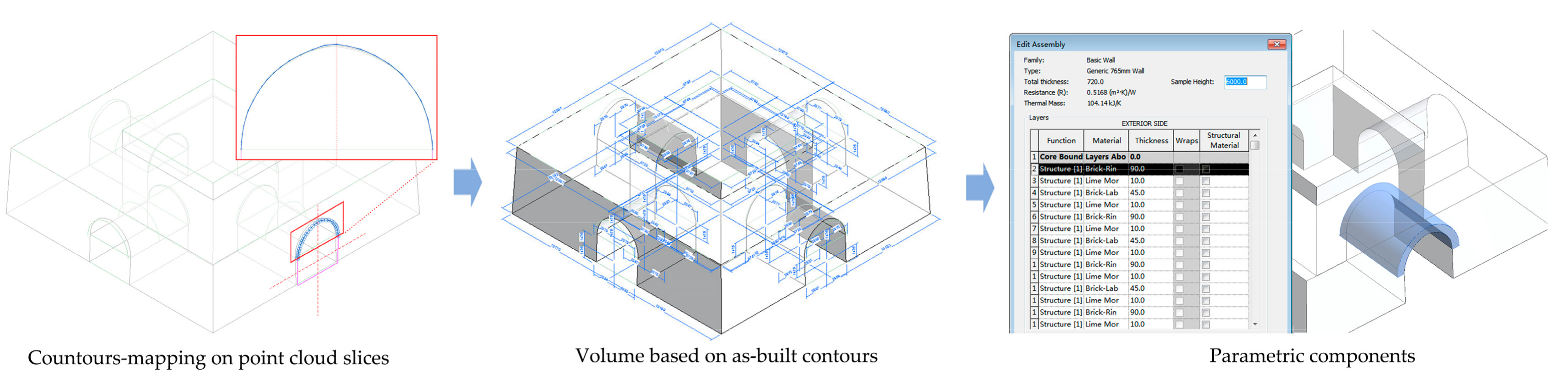
Semantics are attached to components instead of individual brick units in Revit by default. A workflow using auxiliary tools was developed to generate semantic-rich brick units via parametric generation and the IFC proxy (Figure 6).
Hybrid modeling approaches were employed to generate brick units in Rhino by employing its versatile visual programing (via Grasshopper) based on NURBS. The bricks laid on walls were modeled manually with reference to the textured mesh surfaces obtained with photogrammetry. A code was scripted using Grasshopper to automatically generate brick units on the surfaces of the barrel vaults with user-defined parameters (layer amount, brick dimensions and mortar thickness) for facilitating modifications and sustainable uses in similar structures. The composition of Five Rings and Five Label Courses based on stretcher bond served as the logic of parametric modeling:
- A NURBS surface was generated from the slices of the point cloud;
- The surface was divided into rectangles reflecting the stretcher-bond pattern;
- The rectangles were shrunk (considering mortar thickness) and extruded based on brick width and the thickness of each brick layer.
The generated 3D models of brick units were enriched with a parameter using the VisualARQ plugin of Grasshopper. “Damage types” consists of two values (“Crack” and “Impact damage”) based on preliminary observations by the naked eye. The generated brick-unit models were manually grouped to be assigned with the corresponding values and stored in IFC 2 × 3 format for subsequent use in Revit.
3. Results
3.1. LoD 1: In Situ Maintenance
The file size of the LoD 1 model without the images was less than 4 MB; this increased to 21 MB when the 27 relief maps with resolutions in a range 0.5–2 cm/pixel were included. Image processing required approximately 4 h.
Owing to the associated connections of the 3D model and 2D views in BIM, the host model linked by the images allowed for drawing productions on the specific segments of walls and vaults. The damages detected by the naked eye were manually annotated according to the relevant glossaries [52]. In addition, the model and linkages were uploaded to BIM 360 Docs and published for sharing with the stakeholders and for with in situ maintainers for visualization and editing on a tablet computer (Figure 7). Maintainers could compare the earlier damage annotations with the current state and make new annotations. Even though damages such as missing brick units, plants and cracks were noticed on raster images, a few could only be characterized in situ, such as thin fractures and distinguishing weathering from impact damages.
3.2. LoD 2: As-Built Drawings
The LoD 2 model was 11 MB and required approximately 2 h. Most of the time was required for tracing the sections of point clouds, while the generation of components by faces was prompt.
As-built dimensions and deformation analysis were produced from LoD 2 owing to its high accuracy. The mean deviation and standard deviation between the LoD 2 model and TLS-derived mesh (mean error of 3 mm) were 1.6 and 1.2 cm, respectively (Figure 8a). Given the length of the Stele Tower (25.7 m), the relative error was 1/1600 (=1.6 cm/25.7 m). This accuracy considered the severe weathering of brick on exposed surfaces: the point-cloud contours were mapped without including such details. The as-built 3D model improved the accuracy of drawing production and dimension extraction. The sections that passed through the vaults reflected the actual dimensions of construction details (brick courses and mortar). Convenient dimension extraction facilitated the statistical analysis of structural deformation, such as the deformation of the barrel vaults caused by lateral thrusts. The results showed that all barrel vaults experienced this problem. The largest deformation was located at the outer section of the south vault, which was 6 cm longer on the higher level (top) compared to the lower level (bottom) (Figure 8b).
The components were subdivided using “parts” in Revit. This enabled the brickwork laid at different times to be distinguished manually and provided elevations, sections, and isometric views at a fine scale (1:50) (Figure 8c). However, the cost of subdividing components was the loss of the semantic data that were attached to components in Revit. The transition between components and subdivided parts is reversible; they can be switched for an HR survey with different concentrations.
3.3. LoD 3: Damage Contents at the Brick Level
LoD 3 was applied only to the western vault instead of the global structure considering the potential burden of computation. As the modeling of the brick units and the definition of their parameters were automated owing to the scripted code in Grasshopper, the most time was required for manually specifying the values of each brick. The entire process required approximately 1 h, and the Revit file size was 13 MB (composed by 2343 brick units). However, the obtained model was not strictly as-built, as the brick units were generated based on the assumption of stretcher bond without addressing their irregular arrangement caused by slight change in brick length. Manual adjustments would require high labor intensity. The estimated overall file size of the Stele Tower at LoD 3 covering only visible surfaces would be 20 to 30 times the current model. Considerable time would be required when precise brick mapping is performed through manual adaptions.
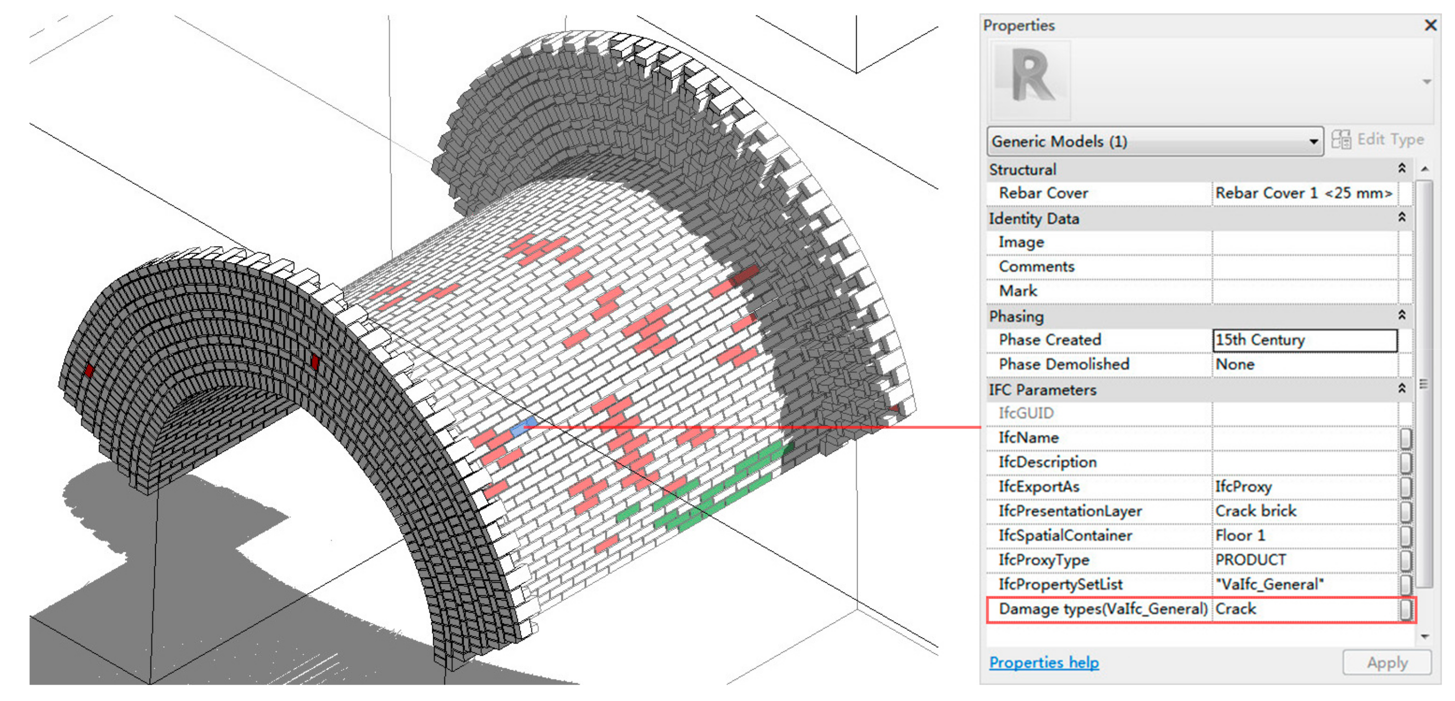
Despite the modeling efforts at a local scale, a BIM representation at the brick level of the Stele Tower was feasible through the combined use of parametric generation and the IFC proxy. The brick units were recognized as “generic model” in Revit, but enriched with custom IFC parameters (i.e., “Damage types”). The values of each brick unit were editable. The brick units were filtered by user-defined logics (Figure 9). The main benefit of LoD 3, in contrast to previous LoDs, is data management at the brick level, which is crucial for the conservation of the studied brick structures. Damage contents were annotated with 2D graphics at LoD 1, temporal changes were represented at the region level by subdividing components at LoD 2, while damages and temporal attributes were stored with assembles of 3D models representing individual brick units at LoD 3.
4. Discussion
Currently, accurate and detailed 3D models with optical measurement technologies are available in the field of architectural heritage even under extreme conditions (e.g., inaccessible areas and narrow spaces). However, data consumers have not sufficiently exploited these advantages. One of the obstacles is in the process from measurement to drawing in a survey workflow. The improvement of as-built accuracy tends to decrease the parametric intelligence of components in HBIM; hence, adopting an appropriate LoD for heritage types and surveys is critical. This study addresses this issue from a brick structure point of view.
4.1. Potential Applications of the Three LoDs
The direct application of LoD 1 is in situ maintenance through the combined use of photogrammetry and BIM on portable devices. This is a promising utilization given Nanjing’s 35 km-long city wall built during the Ming Dynasty. Currently, the damage documentation in daily maintenance relies mostly on photos instead of metric data. It is not possible to detect changes unless they are evident. BIM Models at LoD 1 allow for web-based damage annotation and data sharing for these brick-built heritage sites. A by-product of LoD 1 is the rapid modeling of Ming Dynasty brick structures at the same LoD and a 3D geodatabase. Owing to its highly parametric geometry, the LoD 1 model serves as a prototype for the rapid modeling of the fifteenth-century brick-built counterparts and facilitates a geographical platform. As a volume is driven by two contours (at top and bottom) and penetration by a series of vaulted passages is a shared characteristic, a model can be rapidly adapted to another measurement. This is an efficient survey workflow considering cm-level (accuracy and resolution) 3D measurements conducted to such a structure requires less than 30 min using a hand-held mobile mapping system [4]. In addition, parametric modification from one BIM model to another requires less than 15 min by a skilled operator. The generated models can be georeferenced and visualized with 3D terrain and water for tourist guidance and game development.
As-built accuracy (volume), parametric geometry (bricklayer thickness) and semantic data (materials) are retained at LoD 2. The yielded models satisfy a wide range of applications with reasonable modeling efforts and model sizes. For instance, studies on vaulting geometries in Chinese brick remains have mainly employed preliminary surveys corresponding to LoD 1 in this study [53,54]; the convenience of as-built dimension extraction and data transfer will support such studies. The component-based semantic structure facilitates structural simulation based on as-built geometry and materials. The components yielded at LoD 2 retain complete semantic data as those inherently established (the default “system family”) in Revit, ranging from mechanical properties (density) to thermal properties (thermal conductivity, heat transfer coefficient and thermal resistance). The subdivided components facilitate geometric studies on brick laying among the brick structures built during the Ming and Qing Dynasties.
In additional to the current parameter, more attributes collected through various approaches can be enriched to the model at LoD 3. In the Ming Dynasty, detailed brick kilns were obliged to inscribe on each brick as a method of monitoring brick-making quality. Provenance of brick can be traced by studying these inscriptions. Nondestructive techniques can be employed to detect physical properties at the brick level, such as moisture content [55]. The self-defined IFC parameters provided by OSS tools enable BIM to be a historic brick database that integrates geometric data with dating, provenance and damage types. Further studies can be performed by combining these logics, such as the statistical analysis of cracked bricks with reference to provenance. In this manner, the studied brick structures with semantic data at the brick level can be shared with stakeholders through widely used BIM platforms.
4.2. Limitations and Future Developments
The proposed approaches were developed mainly within the framework of a widely used BIM platform. Limitations exist in the context of the as-built BIM representations of historical brick structures.
First, despite the use of OSS tools at LoD 3, the proposed methods mainly rely on a commercial BIM platform. Even though the operations are straightforward, compromises are required. For example, the barrel vaults were generated using “wall by face” at LoD 2 owing to the constraints of modeling irregular components in Revit. As a result, the generated vaults were semantically recognized as walls. The uses of the IFC proxy proved that self-defined parameters can be attached to BIM models with reasonable modeling efforts, but the use of the IFC model was not sufficiently studied. The IFC model along with the OSS CAD platform, DBMS, and webserver can be employed to customize the BIM representations of historic brick structures. Commercial platforms have advantages over OSS tools in aspects such as user interfaces and drawing production. Connections should be established between the self-defined parameters of OSS tools with the global parameters in commercial platforms.
Second, the brick units generated at LoD 3 are not strictly as-built. The proposed method uses a code to parametrically generate brick models based on average brick dimensions and mortar thickness and neglects their irregular arrangements caused by slight change in brick length. Manual brick-by-brick adjustment is labor intensive. CV algorithms should be tested in the future to automate the process of brick shape detection. Damage mapping on orthoimages is shown to be not flexible by default tools in Revit, while GIS provides versatile operations for establishing thematic maps on damage content through image processing algorithms. CAD-GIS mapping should be combined with the BIM representations in future.
5. Conclusions
This work focused on the as-built modeling of brick-built historic structures in BIM platforms. Three LoDs were proposed for the case study, which was a fifteenth-century UNESCO heritage site in China. The results were assessed in terms of model effects and modeling efforts. The following conclusions can be drawn:
- BIM representations have advantages in terms of centralizing as-built geometries and nongraphical attributes (e.g., damage contents), compared with conventional vector-based methods when applied to brick structures;
- As-built brick walls and vaults represented by parametric components (LoD 300 after BIMForum) can be generated by tracing point clouds, with reasonable modeling efforts, through default workflows in a commercial BIM application (Revit);
- A BIM representation based on individual brick units attached with custom semantics (LoD 400 after BIMForum) is feasible for local parts by employing OSS tools and an IFC proxy. The automated detections of brick shapes are crucial for automating the workflow globally at this LoD.
Author Contributions
Zheng Sun conducted the field measurement and wrote the manuscript; Jiangtao Xie scripted the code; Yingying Zhang validated the generated models; and Yongkang Cao reviewed and edited the manuscript. All the authors have read and approved the manuscript.
Funding
This study was funded by the National Natural Science Foundation of China (51708285, 51678355) and the Natural Science Foundation of Jiangsu Province (BK20171009).
Acknowledgments
The authors would like to thank Guo Huayu and Can Sun from Nanjing Tech University and Yiting Pan from Soochow University for their support in discussing and clarifying the construction methods of brick structures.
Conflicts of Interest
The authors declare no conflict of interest. The funding sponsors had no role in the design of the study; in the collection, analyses, or interpretation of data; in the writing of the manuscript; or in the decision to publish the results.
References
- Campbell, J.W.; Pryce, W. Brick: A World History; Thames & Hudson: London, UK, 2003. [Google Scholar]
- Brumana, R.; Condoleo, P.; Grimoldi, A.; Banfi, F.; Landi, A.G.; Previtali, M. HR LOD based HBIM to detect influences on geometry and shape by stereotomic construction techniques of brick vaults. Appl. Geomat. 2018, 10, 529–543. [Google Scholar] [CrossRef]
- Costa-Jover, A.; Lluis i Ginovart, J.; Coll-Pla, S.; López Piquer, M. Using the terrestrial laser scanner and simple methodologies for geometrically assessing complex masonry vaults. J. Cult. Herit. 2019, 36, 247–254. [Google Scholar] [CrossRef]
- Sammartano, G.; Spanò, A. Point clouds by SLAM-based mobile mapping systems: Accuracy and geometric content validation in multisensor survey and stand-alone acquisition. Appl. Geomat. 2018, 1–23. [Google Scholar] [CrossRef]
- Sun, Z.; Zhang, Y. Accuracy evaluation of videogrammetry using a low-cost spherical camera for narrow architectural heritage: An observational study with variable baselines and blur filters. Sensors 2019, 19, 496. [Google Scholar] [CrossRef] [PubMed] [Green Version]
- Davide, A. Measured and Drawn: Techniques and Practice for The Metric Survey of Historic Buildings, 2nd ed.; Bedford, J., Ed.; English Heritage: Swindon, UK, 2009; ISBN 978-1-84802-047-4. [Google Scholar]
- Apollonio, F.I.; Gaiani, M.; Benedetti, B. 3D reality-based artefact models for the management of archaeological sites using 3D GIS: A framework starting from the case study of the Pompeii Archaeological area. J. Archaeol. Sci. 2012, 39, 1271–1287. [Google Scholar] [CrossRef]
- Banfi, F. BIM orientation: Grades of generation and information for different type of analysis and management process. In Proceedings of the 26th International CIPA Symposium 2017, Ottawa, ON, Canada, 28 August–1 September 2017; Volume XLII-2/W5, pp. 57–64. [Google Scholar]
- Liang, H.; Li, W.; Zhang, Q. Semantic-based 3D information modelling and documentation of rockeries in Chinese Classical gardens: A case study on the rockery at Huanxiu Shanzhuang, Suzhou, China. J. Cult. Herit. 2019, 37, 247–258. [Google Scholar] [CrossRef]
- Lourenço, P.B.; van Hees, R.; Fernandes, F.; Lubelli, B. Characterization and damage of brick masonry. In Structural Rehabilitation of old Buildings; Costa, A., Guedes, J.M., Varum, H., Eds.; Springer: Berlin/Heidelberg, Germany, 2014; Volume 2, pp. 109–130. ISBN 978-3-642-39685-4. [Google Scholar]
- Bertolesi, E.; Adam, J.M.; Rinaudo, P.; Calderón, P.A. Research and practice on masonry cross vaults–A review. Eng. Struct. 2019, 180, 67–88. [Google Scholar] [CrossRef]
- Crespi, P.; Franchi, A.; Ronca, P.; Giordano, N.; Scamardo, M.; Gusmeroli, G.; Schiantarelli, G. From BIM to FEM: The Analysis of an Historical Masonry Building; Wit Press: Bristol, UK, 2015; pp. 581–592. [Google Scholar]
- Roca, P.; Cervera, M.; Gariup, G.; Pela’, L. Structural analysis of masonry historical constructions. classical and advanced approaches. Arch. Comput. Methods Eng. 2010, 17, 299–325. [Google Scholar] [CrossRef] [Green Version]
- Barazzetti, L. Parametric as-built model generation of complex shapes from point clouds. Adv. Eng. Inform. 2016, 30, 298–311. [Google Scholar] [CrossRef]
- Garagnani, S.; Manferdini, A.M. Parametric accuracy: Building Information Modeling process applied to the cultural heritage preservation. In Proceedings of the 3D Virtual Reconstruction and Visualization of Complex Architectures, Trento, Italy, 25–26 February 2013; Volume 5. [Google Scholar]
- Chiabrando, F.; Lo Turco, M.; Rinaudo, F. Modeling the decay in an HBIM starting from 3D point clouds. A followed approach for cultural heritage knowledge. In Proceedings of the 26th International CIPA Symposium 2017, Ottawa, ON, Canada, 8 August–1 September 2017; Volume XLII-2/W5, pp. 605–612. [Google Scholar]
- Giunta, G.; Di Paola, E.; Mörlin Visconti Castiglione, B.; Menci, L. Integrated 3D-database for diagnostics and documentation of Milan’s Cathedral façade. In Proceedings of the CIPA 2005 XX International Symposium, Torino, Italy, 26 September–1 October 2005; Volume 3. [Google Scholar]
- Bryan, P.; Corner, I.; Stevens, D. Digital rectification techniques for architectural and archaeological presentation. Photogramm. Rec. 1999, 16, 399–415. [Google Scholar] [CrossRef]
- Pierrot-Deseilligny, M.; De Luca, L.; Remondino, F. Automated image-based procedures for accurate artifacts 3D modeling and orthoimage generation. Geoinformatics FCE CTU 2011, 6, 291–299. [Google Scholar] [CrossRef]
- Canny, J. A computational approach to edge detection. IEEE Trans. Pattern Anal. Mach. Intell. 1986, 8, 679–698. [Google Scholar] [CrossRef]
- Oses, N.; Dornaika, F.; Moujahid, A. Image-based delineation and classification of built heritage masonry. Remote Sens. 2014, 6, 1863–1889. [Google Scholar] [CrossRef] [Green Version]
- Valero, E.; Bosché, F.; Forster, A. Automatic segmentation of 3D point clouds of rubble masonry walls, and its application to building surveying, repair and maintenance. Autom. Constr. 2018, 96, 29–39. [Google Scholar] [CrossRef]
- Lezzerini, M.; Antonelli, F.; Columbu, S.; Gadducci, R.; Marradi, A.; Miriello, D.; Parodi, L.; Secchiari, L.; Lazzeri, A. Cultural heritage documentation and conservation: Three-dimensional (3D) laser scanning and Geographical Information System (GIS) techniques for thematic mapping of facade stonework of St. Nicholas Church (Pisa, Italy). Int. J. Archit. Herit. 2016, 10, 9–19. [Google Scholar] [CrossRef]
- Salonia, P. Historical buildings and their decay: Data recording, analysing and transferring in an ITC environment. In Proceedings of the Vision Techniques for Digital Architectural and Archaeological Archives, Ancona, Italy, 1–3 July 2003; p. 5. [Google Scholar]
- Campanaro, D.M.; Landeschi, G.; Dell’Unto, N.; Touati, A.-M.L. 3D GIS for Cultural Heritage Restoration: A ‘white Box’workflow. J. Cult. Herit. 2016, 18, 321–332. [Google Scholar] [CrossRef]
- Eastman, C.; Teicholz, P.; Sacks, R.; Liston, K. BIM Handbook: A Guide to Building Information Modeling for Owners, Managers, Designers, Engineers and Contractors, 2nd ed.; John Wiley & Sons: New York, NY, USA, 2011. [Google Scholar]
- Murphy, M.; McGovern, E.; Pavia, S. Historic Building Information Modelling–adding intelligence to laser and image based surveys of European Classical architecture. ISPRS J. Photogramm. Remote Sens. 2013, 76, 89–102. [Google Scholar] [CrossRef]
- Pocobelli, D.P.; Boehm, J.; Bryan, P.; Still, J.; Grau-Bové, J. BIM for heritage science: A review. Herit. Sci. 2018, 6. [Google Scholar] [CrossRef] [Green Version]
- Hichri, N.; Stefani, C.; De Luca, L.; Veron, P. Review of the “as-buit BIM” approaches. In Proceedings of the 3D-ARCH International Conference, Trento, Italy, 25–26 February 2013. [Google Scholar]
- Fai, S.; Rafeiro, J. Establishing an appropriate level of detail (LoD) for a Building Information Model (BIM) -West Block, Parliament Hill, Ottawa, Canada. In Proceedings of the ISPRS Annals of Photogrammetry, Remote Sensing and Spatial Information Sciences, Riva del Garda, Italy, 23–25 June 2014; Volume II–5, pp. 123–130. [Google Scholar]
- BIM forum Level of Development specification. Available online: https://bimforum.org/lod/ (accessed on 29 July 2019).
- AEC (UK) 2015 AEC (UK) BIM Technology Protocol. Practical implementation of BIM for the UK Architectural, Engineering and Construction (AEC) industry. AEC (UK). Available online: https://aecuk.files.wordpress.com/2015/06/aecukbimtechnologyprotocol-v2-1-1-201506022.pdf (accessed on 20 November 2019).
- Bruno, N.; Roncella, R. A restoration oriented HBIM system for cultural heritage documentation: The case study of Parma Cathedral. In Proceedings of the ISPRS-International Archives of the Photogrammetry, Remote Sensing and Spatial Information Sciences, Riva del Garda, Italy, 4–7 June 2018; Volume XLII–2, pp. 171–178. [Google Scholar]
- UNI 11337:2017, Part 4. Available online: http://store.uni.com/catalogo/index.php/uni-11337-4-2017.html (accessed on 15 November 2019).
- Historic England. BIM for Heritage: Developing a Historic Building Information Model; Historic England: Swindon, UK, 2017. [Google Scholar]
- Barazzetti, L.; Banfi, F.; Brumana, R.; Gusmeroli, G.; Previtali, M.; Schiantarelli, G. Cloud-to-BIM-to-FEM: Structural simulation with accurate historic BIM from laser scans. Simul. Model. Pract. Theory 2015, 57, 71–87. [Google Scholar] [CrossRef]
- Fassi, F.; Achille, C.; Mandelli, A.; Rechichi, F.; Parri, S. A new idea of BIM system for visualization, web sharing and using huge complex 3D models for facility management. In Proceedings of the 3D Virtual Reconstruction and Visualization of Complex Architectures, Avila, Spain, 25–27 February 2015; Volume XL-5/W4, pp. 359–366. [Google Scholar]
- Gentry, R.; Cavieres, A.; Biggs, D. Building Information Modeling for masonry: Defining and modeling masonry walls. In Proceedings of the 9thInternational Masonry Conference 2014 in Guimarães, Guimarães, Portugal, 7–9 July 2014. [Google Scholar]
- Gentry, T.R.; Sharif, S.; Cavieres, A.; Biggs, D. BIM schema for masonry units and walls. In Proceedings of the Brick and Block Masonry, Padova, Italy, 26–30 June 2016; Modena, C., da Porto, F., Valluzzi, M.R., Eds.; CRC Press: Boca Raton, FL, USA, 2016; pp. 629–636. [Google Scholar]
- Brumana, R.; Condoleo, P.; Grimoldi, A.; Landi, A.G. Shape and construction of brick vaults, criteria, methods and tools for a possible catalogue. In Proceedings of the 2017 Geomatics & Restoration–Conservation of Cultural Heritage in the Digital Era, Florence, Italy, 22–24 May 2017; Volume XLII-5/W1, pp. 137–143. [Google Scholar]
- Brumana, R.; Della Torre, S.; Oreni, D.; Previtali, M.; Cantini, L.; Barazzetti, L.; Franchi, A.; Banfi, F. HBIM challenge among the paradigm of complexity, tools and preservation: The Basilica di Collemaggio 8 years after the earthquake (L’ Aquila). In Proceedings of the 26th International CIPA Symposium 2017, Ottawa, ON, Canada, 28 August–1 October 2017; Volume XLII-2/W5, pp. 97–104. [Google Scholar]
- López, F.; Lerones, P.; Llamas, J.; Gómez-García-Bermejo, J.; Zalama, E. A review of heritage Building Information Modeling (H-BIM). Multimodal Technol. Interact. 2018, 2, 21. [Google Scholar] [CrossRef] [Green Version]
- Diara, F.; Rinaudo, F. Open source HBIM for cultural heritage: A project proposal. In Proceedings of the 2018 ISPRS TC II Mid-term Symposium “Towards Photogrammetry 2020”, Riva del Garda, Italy, 4–7 June 2018; Volume XLII–2, pp. 303–309. [Google Scholar]
- Barazzetti, L.; Banfi, F.; Brumana, R.; Previtali, M. Creation of parametric BIM objects from point clouds using NURBS. Photogramm. Rec. 2015, 30, 339–362. [Google Scholar] [CrossRef]
- Bruno, N.; Roncella, R. HBIM for conservation: A new proposal for information modeling. Remote Sens. 2019, 11, 1751. [Google Scholar] [CrossRef] [Green Version]
- Yang, X.; Lu, Y.-C.; Murtiyoso, A.; Koehl, M.; Grussenmeyer, P. HBIM modeling from the surface mesh and its extended capability of knowledge representation. ISPRS Int. J. Geo-Inf. 2019, 8, 301. [Google Scholar] [CrossRef] [Green Version]
- Esri and Autodesk—What’s Next? Available online: http://www.esri.com/~/media/Images/Content/landing-pages/autodesk/Esri_ADSK_Vision_Paper_Template_FINAL (accessed on 15 November 2019).
- Logothetis, S.; Karachaliou, E.; Stylianidis, E. From OSS CAD to BIM for cultural heritage digital representation. In Proceedings of the 2017 3D Virtual Reconstruction and Visualization of Complex Architectures, Nafplio, Greece, 1–3 March 2017; Volume XLII-2/W3, pp. 439–445. [Google Scholar]
- Eynon, J. Construction Manager’s BIM Handbook; John Wiley & Sons: New York, NY, USA, 2016. [Google Scholar]
- Logothetis, S.; Valari, E.; Karachaliou, E.; Stylianidis, E. Spatial DMBS architecture for a free and open source BIM. In Proceedings of the 26th International CIPA Symposium 2017, Ottawa, Canada, 28 September–1 October 2017; Volume XLII-2/W5, pp. 467–473. [Google Scholar]
- IfcProxy. Available online: http://standards.buildingsmart.org/IFC/RELEASE/IFC2x3/TC1/HTML/ifckernel/lexical/ifcproxy.htm (accessed on 20 November 2019).
- Balen, K.; van Binda, L.; Van Hees, R.P.; Franke, L. Damage to historic brick masonry structures. Masonry damage diagnostic system and damage atlas for evaluation of deterioration. In Proceedings of the 8th International Congress on Deterioration and Conservation of Stone, Berlin, Germany, 30 September–4 October 1996; pp. 1687–1693. [Google Scholar]
- Wang, Q. The basic form of vault geometry in the Qing Dynasty. Tradit. Chin. Archit. Gard. 1987, 5, 53–55. [Google Scholar]
- Chang, Q. On the origin of brick and stone vaulted structures in the Han Dynasty. Stud. Hist. Nat. Sci. 1991, 10, 288–295. [Google Scholar]
- Pocobelli, D.P.; Boehm, J.; Bryan, P.; Still, J.; Grau-Bové, J. Building Information Models for monitoring and simulation data in heritage buildings. In Proceedings of the ISPRS TC II Mid-term Symposium “Towards Photogrammetry 2020”, Riva del Garda, Italy, 4–7 June 2018; Volume XLII–2, pp. 909–916. [Google Scholar]
Figure 1.
Incomplete map of Ming Dynasty brick-built ruins in Nanjing, China.

Figure 2.
Stele Tower. (a) From northwest; (b) interior from southeast; (c) the east vault laid with Five Rings and Five Label Courses; (d) new brickwork overlapped on the original; (e) close-up of the brickwork.
Figure 2.
Stele Tower. (a) From northwest; (b) interior from southeast; (c) the east vault laid with Five Rings and Five Label Courses; (d) new brickwork overlapped on the original; (e) close-up of the brickwork.

Figure 3.
Optical measurements conducted on the Stele Tower. (a) TLS using a Leica BLK360; (b) point cloud derived from TLS; (c) mesh generated from surface reconstruction; (d,e) Textured mesh of (d) the east façade and (e) the west vault derived using photogrammetry.
Figure 3.
Optical measurements conducted on the Stele Tower. (a) TLS using a Leica BLK360; (b) point cloud derived from TLS; (c) mesh generated from surface reconstruction; (d,e) Textured mesh of (d) the east façade and (e) the west vault derived using photogrammetry.

Figure 4.
Modeling workflow of LoD 1: As-built images are attached to the surfaces of the parametric model.
Figure 4.
Modeling workflow of LoD 1: As-built images are attached to the surfaces of the parametric model.

Figure 5.
Modeling workflow of LoD 2, for semantic-rich components with as-built geometry.

Figure 6.
Modeling workflow of LoD 3. Parametric modeling of brick units and IFC parameter customization.
Figure 6.
Modeling workflow of LoD 3. Parametric modeling of brick units and IFC parameter customization.
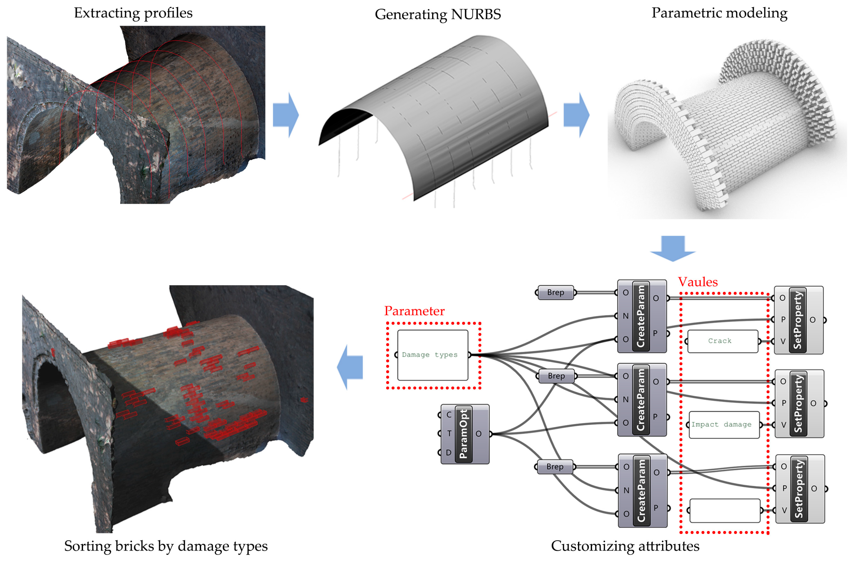
Figure 7.
Checking and annotating brick damages on portable devices in situ. (a) BIM model allowing for damage mapping of each surface; (b) in situ damage annotation, feedback, and change detection.
Figure 7.
Checking and annotating brick damages on portable devices in situ. (a) BIM model allowing for damage mapping of each surface; (b) in situ damage annotation, feedback, and change detection.

Figure 8.
As-built dimensions and deformation statistics produced at LoD 2 owing to its high accuracy. (a) Accuracy of the model validated by the TLS-derived mesh; (b) drawings and deformation statistics extracted from the 3D model. In the chart, the sections are named according to their orientations and locations (joining with inner walls or outer walls). EI—east inner; EO—east outer; WO—west outer; SI—south inner; SO—south outer; NI—north inner; NO—north outer; (c) Elevation, section and isometric view.
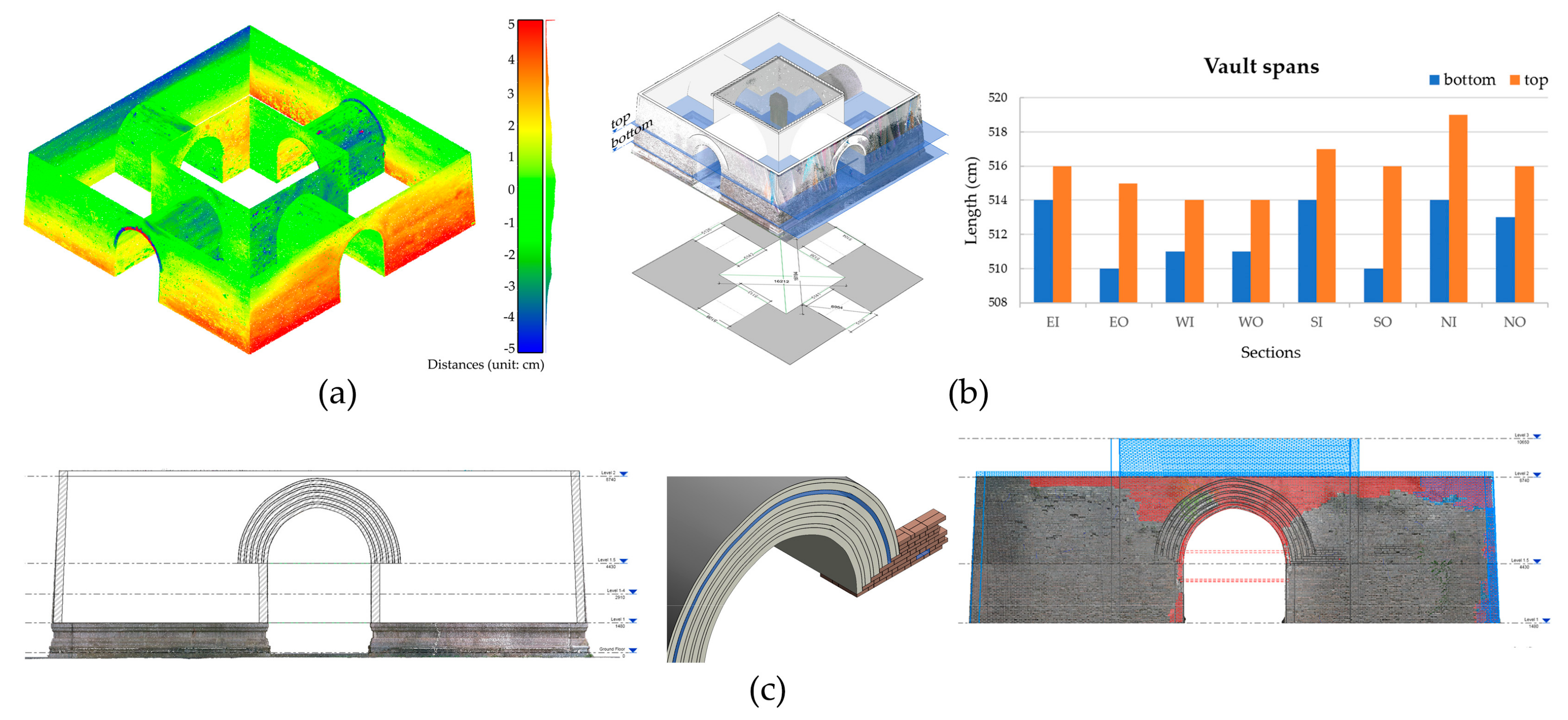
Figure 9.
Filtering brick units by their damage types in BIM. “Crack” bricks and “Impact damage” bricks were shown in red and green, respectively.
Figure 9.
Filtering brick units by their damage types in BIM. “Crack” bricks and “Impact damage” bricks were shown in red and green, respectively.
© 2019 by the authors. Licensee MDPI, Basel, Switzerland. This article is an open access article distributed under the terms and conditions of the Creative Commons Attribution (CC BY) license (http://creativecommons.org/licenses/by/4.0/).
Share and Cite
MDPI and ACS Style
Sun, Z.; Xie, J.; Zhang, Y.; Cao, Y. As-Built BIM for a Fifteenth-Century Chinese Brick Structure at Various LoDs. ISPRS Int. J. Geo-Inf. 2019, 8, 577. https://0-doi-org.brum.beds.ac.uk/10.3390/ijgi8120577
AMA Style
Sun Z, Xie J, Zhang Y, Cao Y. As-Built BIM for a Fifteenth-Century Chinese Brick Structure at Various LoDs. ISPRS International Journal of Geo-Information. 2019; 8(12):577. https://0-doi-org.brum.beds.ac.uk/10.3390/ijgi8120577
Chicago/Turabian StyleSun, Zheng, Jiangtao Xie, Yingying Zhang, and Yongkang Cao. 2019. "As-Built BIM for a Fifteenth-Century Chinese Brick Structure at Various LoDs" ISPRS International Journal of Geo-Information 8, no. 12: 577. https://0-doi-org.brum.beds.ac.uk/10.3390/ijgi8120577
Note that from the first issue of 2016, this journal uses article numbers instead of page numbers. See further details here.