A Modified Methodology for Generating Indoor Navigation Models


1
Faculty of Geodesy, Geospatial and Civil Engineering, University of Warmia and Mazury in Olsztyn, 10-719 Olsztyn, Poland
2
Department of Geoinfirmatics and Applied Computer Science, Faculty of Geology, Geophysics and Environmental Protection, AGH University of Science and Technology, 30-059 Krakow, Poland
*
Author to whom correspondence should be addressed.
ISPRS Int. J. Geo-Inf. 2019, 8(2), 60; https://0-doi-org.brum.beds.ac.uk/10.3390/ijgi8020060
Submission received: 18 December 2018
/
Revised: 22 January 2019
/
Accepted: 24 January 2019
/
Published: 29 January 2019
(This article belongs to the Special Issue Multidimensional and Multiscale GIS)
Abstract
:Automatic methods for constructing navigation routes do not fully meet all requirements. The aim of this study was to modify the methodology for generating indoor navigation models based on the Medial Axis Transformation (MAT) algorithm. The simplified method for generating corridor axes relies on the Node-Relation Structure (NRS) methodology. The axis of the modeled structure (corridor) is then determined based on the points of the middle lines intersecting the structure (polygon). The proposed solution involves a modified approach to the segmentation of corridor space. Traditional approaches rely on algorithms for generating Triangulated Irregular Networks (TINs) by Delaunay triangulation or algorithms for generating Thiessen polygons known as Voronoi diagrams (VDs). In this study, both algorithms were used in the segmentation process. The edges of TINs intersected structures. Selected midpoints on TIN edges, which were located in the central part of the structure, were used to generate VDs. Corridor structures were segmented by polygon VDs. The identifiers or structure nodes were the midpoints on the TIN edges rather than the calculated centroids. The generated routes were not zigzag lines, and they approximated natural paths. The main advantage of the proposed solution is its simplicity, which can be attributed to the use of standard tools for processing spatial data in a geographic information system.
1. Introduction
Route navigation is being expanded to cover the entire geographic space, and outdoor navigation is emerging as a separate concept from indoor navigation. The role of indoor navigation (navigation inside buildings) [1,2] is to complement outdoor navigation, and it is implemented mainly in large public utility buildings.
Flat 2D network models are developed based on floor plans. Their height can be represented by attribute H, and such systems are referred to as 2.5D models. 3D models are generated by taking into account the plans of successive building floors. Navigation relies on a geometric model of networks written in mathematical graph structures in the form of a geometric graph [3] with nodes N (NOD) and edges E (EDGE). In a graph model of a network, nodes N represent significant elements of the plan, such as:
- structures (rooms, corridors, stairs),
- lines (doors, windows, entrances).
Nodes representing structures are generally the centroids of those structures. Lines are also represented by centroids, which are the midpoints of entrance lines. Nodes are described by coordinates in a given reference system. Semantic data describing objects are represented by node attributes. In the model, edges represent route sections and possible traffic flows. In indoor navigation, digital geometric network models for navigating people should account for natural movement patterns inside a building. The generated routes should not run close to walls or obstacles.
For many years, researchers have sought to develop a methodology for the automatic generation of indoor navigation models [4,5,6]. Two main types of methods have been proposed: geometric methods that support the generation of Geometric Network Models (GNM) and grid methods for developing Regular Grid Models (RGM) [7]. Geometric methods rely on the topological relations between neighboring structures [4,8], and they are referred to as Node-Relation Structure (NRS) models. A Node-Relation Structure is represented by graphs composed of nodes and edges. The nodes are usually centroids that identify structures. Network edges are lines connecting the centroids of the neighboring structures. A similar method of representation is used in the grid model. The elements of the grid constitute structures [9,10,11]. Structures are usually described with the use of semantic data, such as type of use. A building can be composed of corridors, rooms, and stairs. The NRS model features sub-graphs describing only the relations that are based on semantic data, such as (corridor–room) relations. Lee [4,8] developed a method for transforming the NRS model into a network with the use of the Medial Axis Transformation (MAT) algorithm, which has been extensively described in the literature [12,13,14]. The MAT algorithm has also been deployed in other solutions [7,15]. The results were generally satisfactory, but in open spaces (crossing paths), the generated lines were curved. Certain modifications, such as increasing the density of the initial model, are required to eliminate curved lines [16]. However, this method generates lines that only approximate the real middle line [17]. Numerous solutions have been proposed to deal with this problem [18,19].
Other geometric solutions [19,20,21,22,23] take into account openings, such as doors. In the network model, openings are represented by nodes. In this case, models are constructed based on corridor–entrance, entrance–room, or corridor–corridor relations. The relevant methodology can be referred to as a Node-Relation Structure and Entrance (NRSE) model. Many solutions of this type have been discussed in the literature [24,25,26]. They account for the attributes describing room and entrance functions.
Other methods for generating models are based on structure segmentation. Delaunay triangulation algorithms for generating Triangulated Irregular Networks (TINs) [15,27] or Thiessen polygons, referred to as Voronoi diagrams (VDs) [1], are used for segmentation. Selected points from the analyzed structures (entrances, turn points in wall contour lines) are the basic elements for developing TINs and VDs. The network is constructed with the NRS method based on the segments generated from TINs and VDs. The centroids of the neighboring segments from TIN or VD are connected by edges [7,28]. TIN and VD polygons have also been applied to increase segmentation options [21,22,28]. In these solutions, navigation networks with different resolution are generated automatically subject to need. A network is developed based on the NRS method, but the structures are TIN triangles or VD polygons. The paths generated by network models based on TIN and VD segmentation are usually zigzag lines, which need to be simplified and smoothed with additional algorithms [29].
In other studies [27,30,31], solutions involving TIN and VD structures were used to develop networks based on polygon nodes and midpoints of TIN edges or based on VD edges only. Despite the achieved progress, new attempts are being made to find more effective methods for the automatic generation of networks in large multi-planar spaces, such as shopping centers, airports, and sports stadiums [31,32,33,34,35,36,37,38]. The developed solutions will facilitate the automatic generation of networks that meet the relevant requirements. Lewandowicz and Lisowski [39,40] proposed a novel segmentation method for the automatic generation of networks based on geometric data. Automatically generated routes make a reference to MAT solutions.
The presented study is a continuation of the previous research conducted from 2006 to 2015 [20]. 3D models of selected university buildings and traffic route networks were developed by Kodzik [41] as part of a diploma thesis. The models were linked with a database of attributes relating to indoor premises [20]. In the present study, attempts were made to model routes in successive buildings. The modeling process in buildings was automated. Based on the literature and the results of numerous tests, a method for the automatic generation of network models in buildings was developed with the use of the floor plans presented by Lewandowicz and Lisowski [39]. In this study, the previously proposed methodology was modified, and it is presented below. The obtained results were compared with the previously developed models. They were also presented in a new object.
2. Research Objective and Methods
The aim of this study was to propose a new method for the automatic generation of indoor navigation networks based on the floor plan. The proposed method is easy to use, and it involves simple transformations of geometric data from floor plans. It should be noted that the proposed method was initially tested on cadastral data. The axis of a road lane was mapped based on road parcels [38]. During successive attempts, the corridor segmentation method was evaluated based on various sets of base points [37]. The method proposed in this study relies on a new approach to the segmentation of structures. The applied segmentation method minimizes the irregularity of segments by dividing space across corridors. According to Lewandowicz and Lisowski [39], the segmentation process should rely on points marking the vertices of partition walls. The method proposed in this study has been expanded to include new elements that minimize route zigzagging.
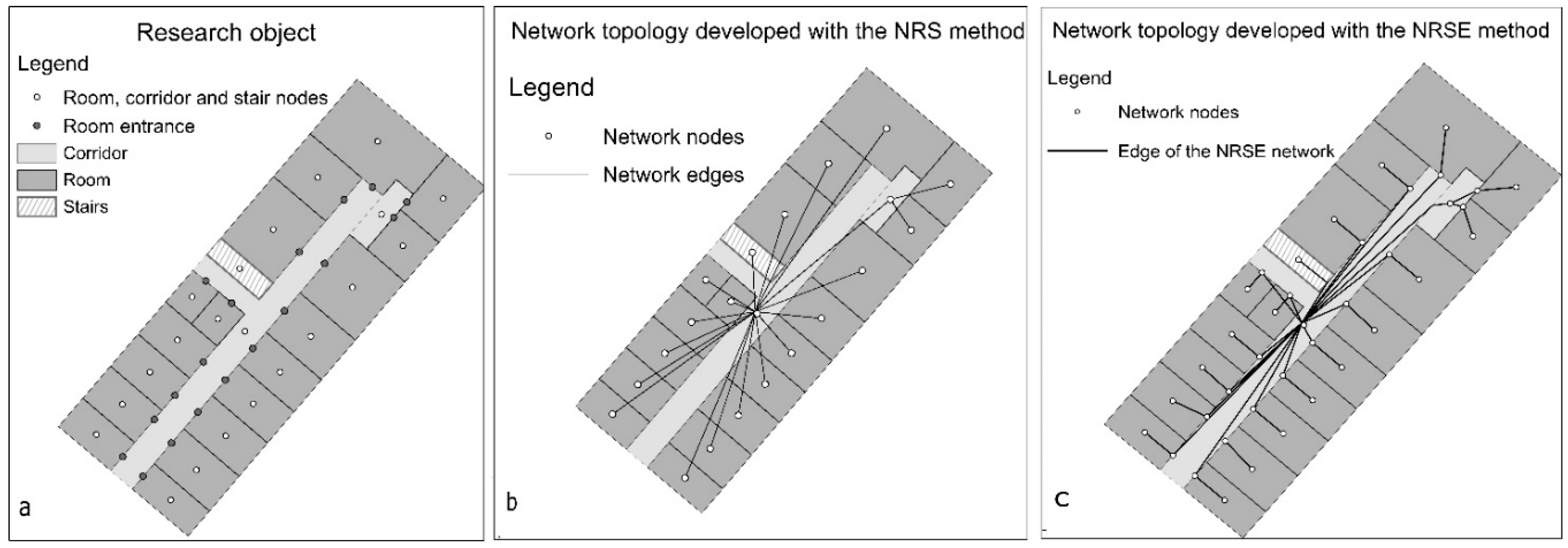
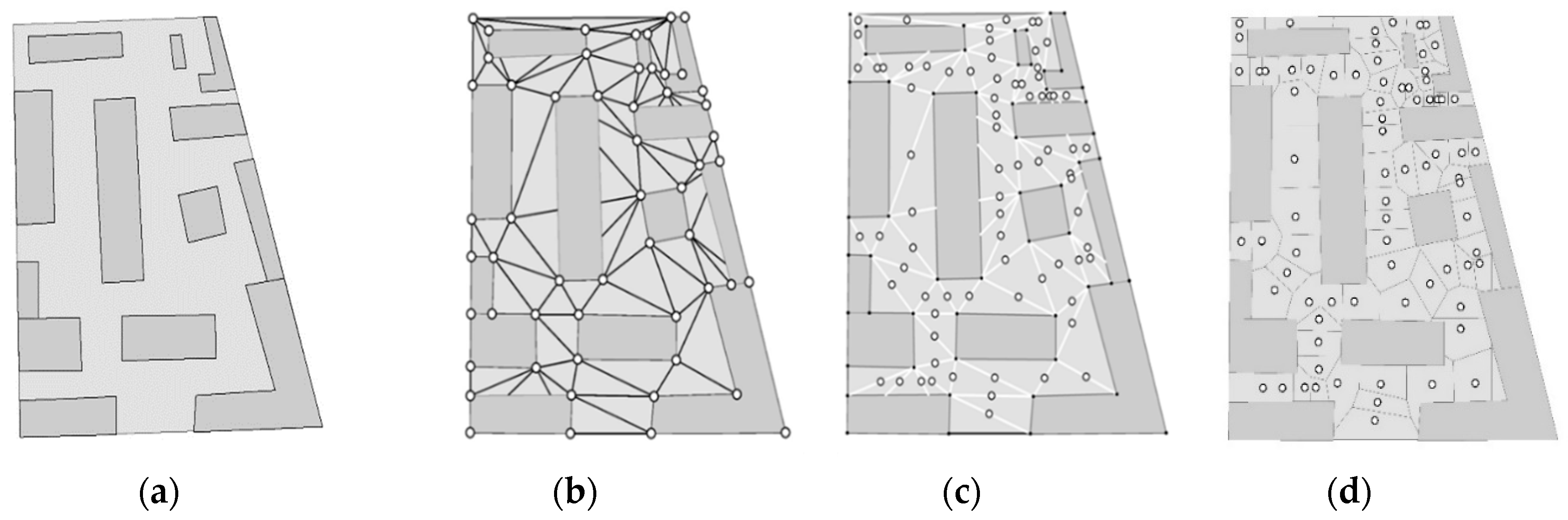
The analyzed object was one floor of a building (Figure 1a). The network models generated with the use of classical methods, the NRS model (corridor–entrance), and the NRSE model (corridor–entrance–room) are presented in Figure 1b,c.
The network models generated with the use of the NRS and NRSE methods are not suitable for navigation. Network edges intersect building walls at locations where traffic cannot exit the building (Figure 2b). The fragments of the network in corridor space have to be modified because they do not reflect traffic routes. In an attempt to propose a new method for generating navigation network models, the authors focused on solutions that generate routes in corridors and integrate these routes with the neighboring objects.
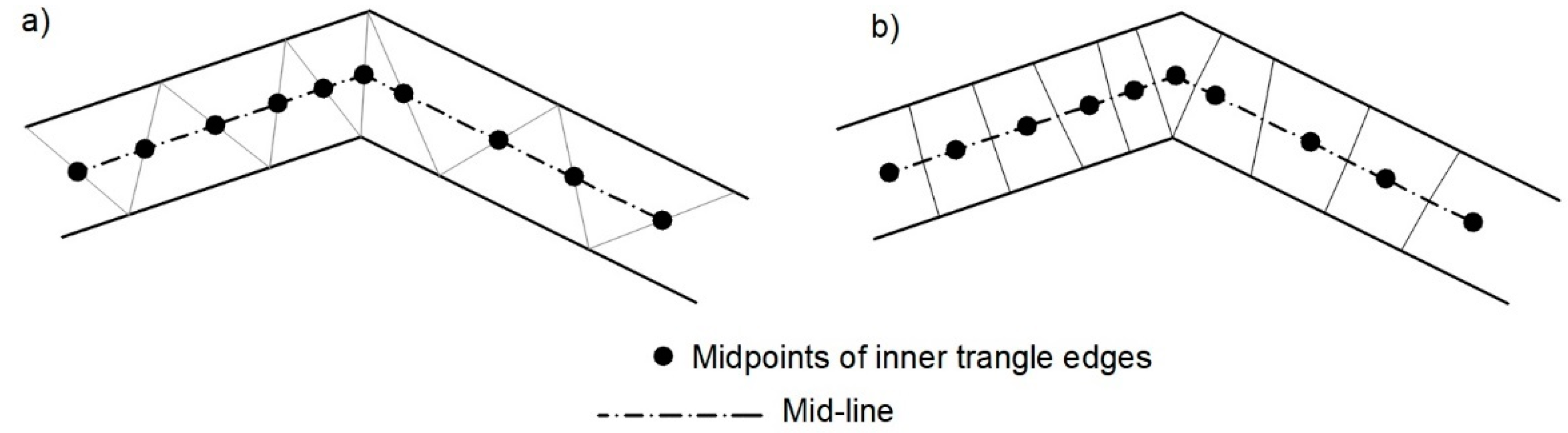
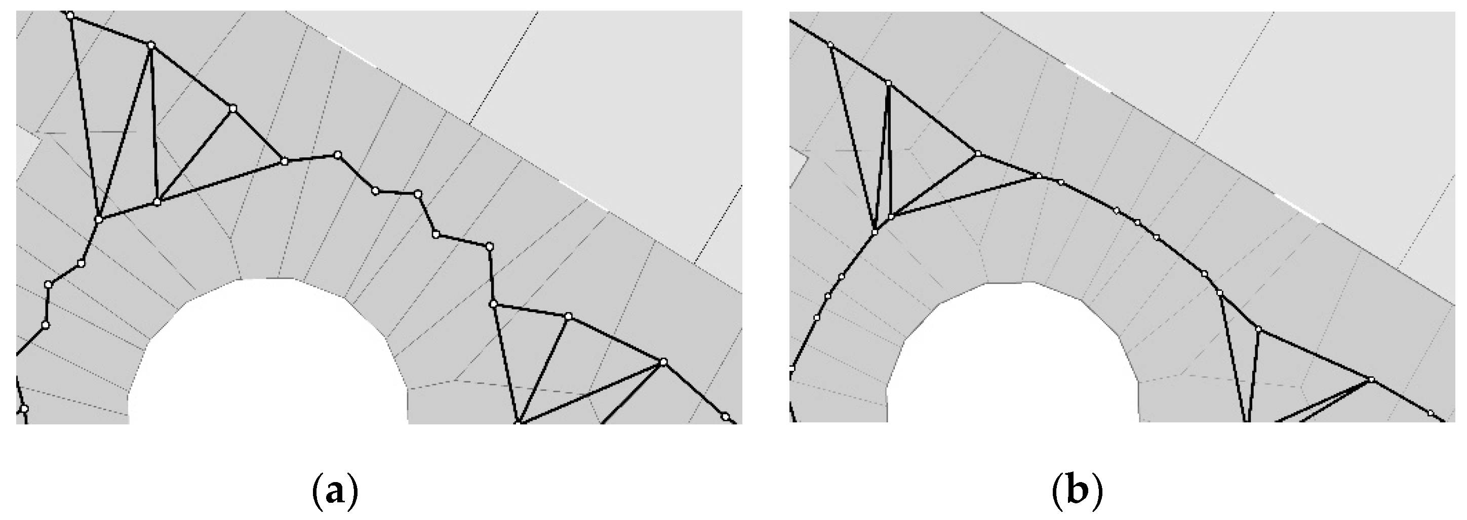
A route was generated in corridor space based on a geometric relationship that is used to manually edit the axes of elongated objects (Figure 2a) in Geographic Information System (GIS). The middle line, such as a route, is plotted based on the midpoints {PMid} of a zigzag line. A zigzag line should be based on the points located along the edges (corridor) of structure S, with at least two turning points on the boundary of structure S. Midpoints {PMid} should be mapped based on sections (edges) of the zigzag line located inside structure S (Figure 2a). To construct an axis in the NRS model, structure S should be segmented in such a manner as to ensure that segmentation {SS} intersects the building and that the midpoints of the zigzag lines {PMid} are located within the segments {SS} (Figure 2b). Midpoints {PMid} are the segment {SS} nodes. After data transformation, the object’s axis can be generated automatically based on segments {SS} with the use of the NRS [4] method. This approach can be referred to as the Middle-Point Relation Structure Segment (MPRSS).
The methodology for generating indoor navigation models [39] was modified. The Node-Relation Structure Segment (NRSS) method of generating a topological network based on nodes that are centroid segments was described in [39]. In the presented modification, midpoints {PMid} are adopted as segment nodes. This minor change considerably influences the shape of the network. The MPRSS method of developing a network is described below. The MPRSS methodology makes a reference to the NRSS method, which is presented in [39].
In the MPRSS method, the network model is developed by:
- adopting a set of base points {Pb} from the floor plan (e.g., points representing the vertices of walls and partition walls),
- generating a zigzag line with the Constrained Delaunay Triangulation (CDT) tool for constructing a Triangulated Irregular Network (TIN) based on {Pb},
- selecting edges {Ezigzag} from the TINs located inside the segmented structure S,
- mapping the midpoints {PMid} of edges {Ezigzag},
- generating a Voronoi diagram (VD) based on a set of midpoints {PMid},
- segmenting object S based on VD, i.e., transforming S into a set of segments S→ {SS},
- assigning a point from the {PMid} set to every segment {SS},
- generating the axis of structure S by developing a topological neighborhood model based on a set of segments {SS} and {PMid}; in this solution, only the relations between segment edges and the left and right polygon are analyzed.
The generated axis of structure S is based on points {PMid}, which are regarded as identification nodes. In the described approach, the MAT algorithm, which is popularly used to determine the axes of polygonal objects, has been replaced with simple transformations. The presented method for generating segments {SS} and object axes was applied only to corridors during the construction of an indoor navigation model.
When the developed network covers an entire floor, additional network edges should be generated based on segment–room relations. When room entrances are taken into account, segment–entrance–room relations should be generated. In this case, the network generation method is referred to as the Middle-Point Relation Structure Segment Entrance (MPRSSE) approach.
The MPRSS and MPRSSE methods will be presented in detail based on mock data models. A new methodology termed Middle-Point Relation Structure Segment Entrance Modification (MPRSSEM) was proposed to combine the MPRSS and MPRSSE approaches. The relations from the MPRSS model (segment–room) were written in the MPRSSEM model as (segment–entrance–room) relations.
The MPRSS, MPRSSE, and MPRSSEM topological-semantic networks modeling navigation routes on a single floor are represented by graphs. The shortest routes can be generated by describing the edges of a graph with edge lengths in the adopted units of measurement. Route lengths represent the differences in the results. In the proposed methodology, GIS tools were used to transform data. The shortest routes were generated with the Distkri algorithm.
3. Results
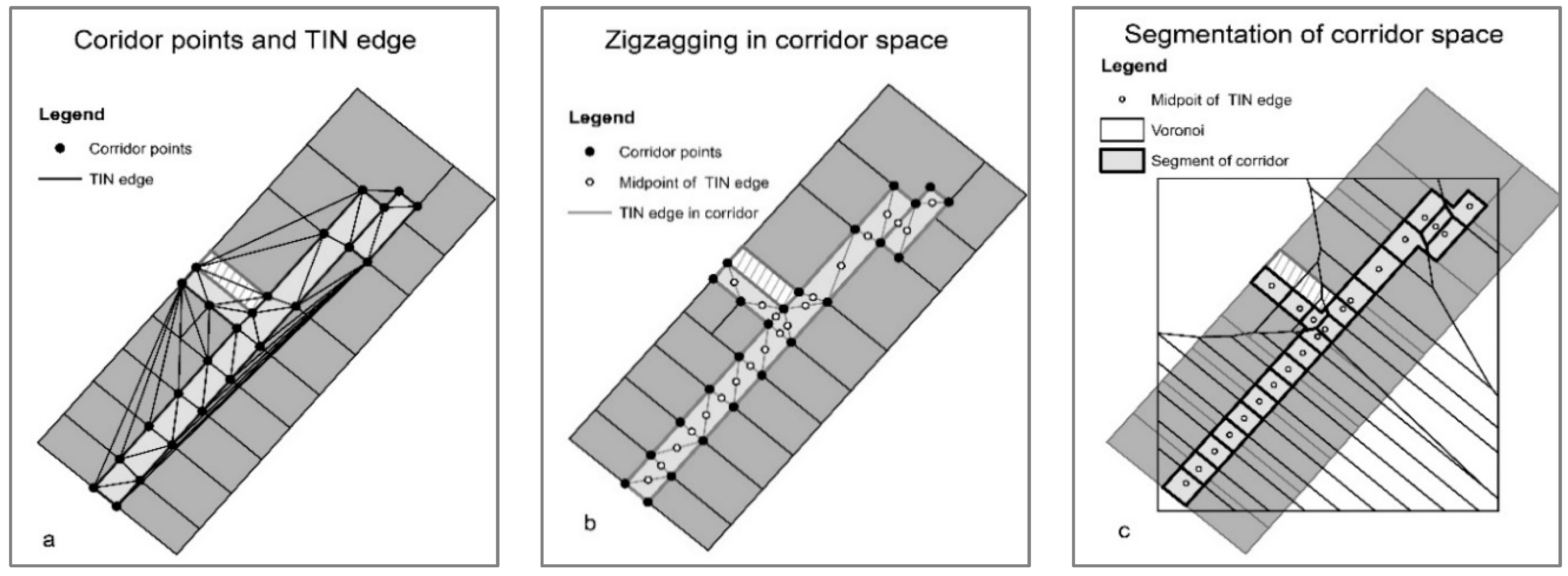
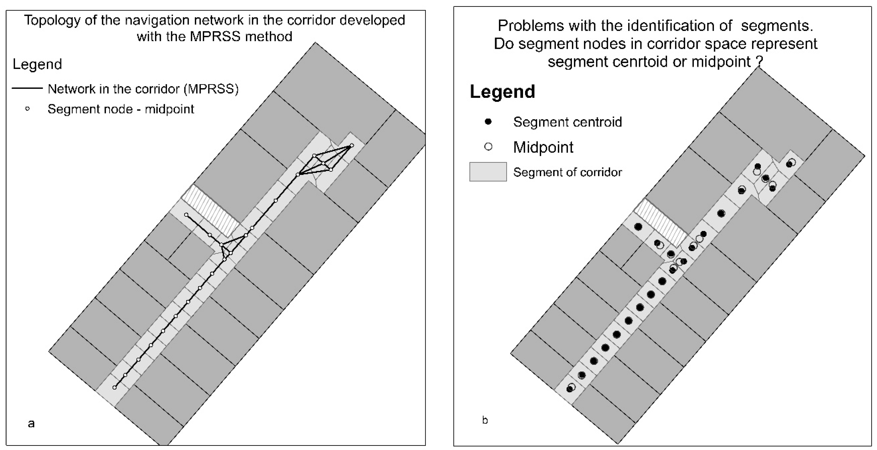
A zigzag line in the corridor (Figure 3a) and the segmentation of corridor space with the use of the VD algorithm are shown in Figure 3b to present the results of the proposed methodology. An indoor navigation model was generated in the corridor based on the segmented corridor space (Figure 4a). The model was developed with the MPRSS method based on neighborhood relations (SS-SS). The network occupies the middle of the corridor based on its midpoints {PMid}. In a straight corridor, network fragments are straight lines. Network elements have a more complex structure at turns in the expanded corridor space (Figure 4a). If the identifiers {SS} were segment centroids CSEG, the generated line would not be straight because {CSEG} ≠ {PMid} (Figure 4b).
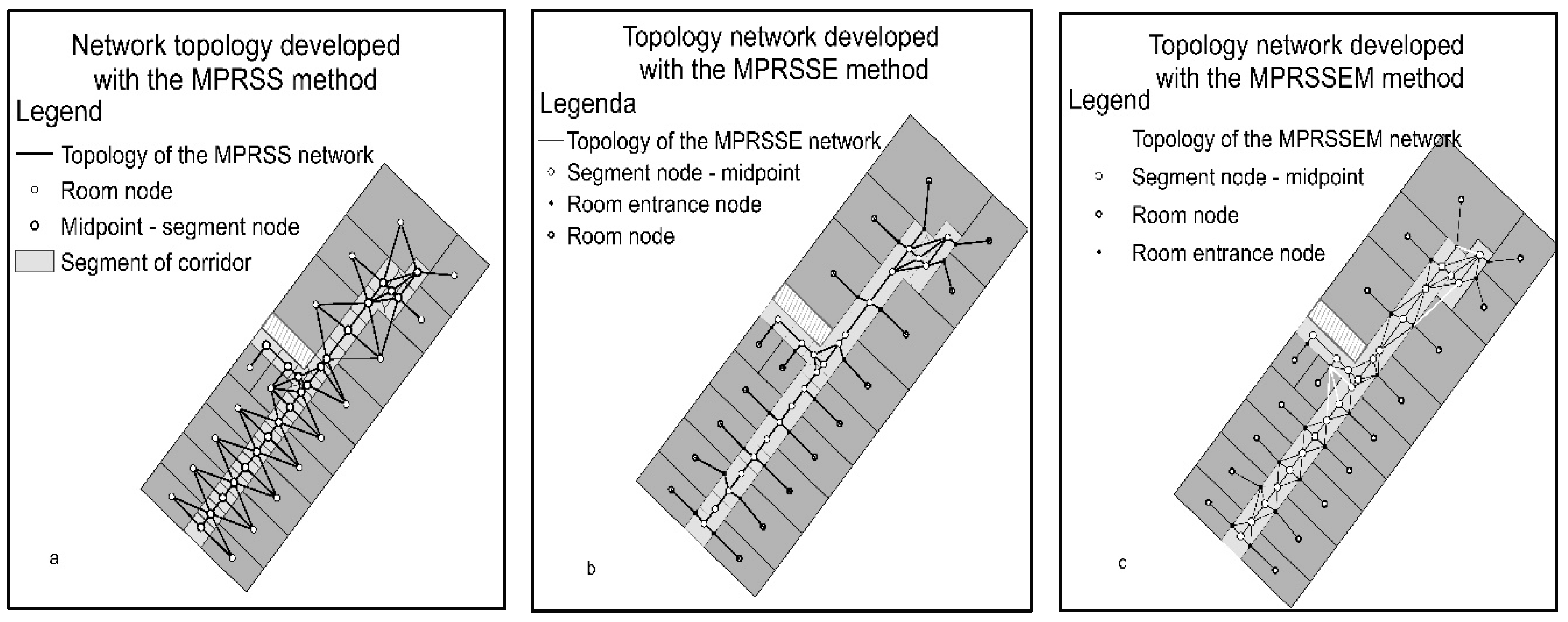
Three models were developed in the process of constructing indoor navigation models that account for corridors and rooms:
- The MPRSS model (Figure 5a) based on (segment–segment), (segment–room), or (segment–stairs) relations,
- The MPRSSE model (Figure 5b) based on (segment–segment), (segment–entrance), (entrance–room), or (segment–stairs) relations,
- The MPRSSEM model combining the relationships from models 1 and 2 (Figure 5c).
The MPRSSEM model was generated by modifying the MPRSSE algorithm. The (segment–room) relations from the MPRSS model were presented as (segment–entrance–room) relations in the MPRSSE model. As a result of the modification (Figure 5c), five edges of the MPRSSEM model do not fit the corridor space (marked in white) and had to be removed by the algorithm. An edge can also be added between each entrance and the adjacent segment of the corridor. In this case, there would be no edges marked in white in Figure 5c.
The network model in Figure 5a could be useful if there were no partition walls on the side of the corridor. The models that account for entrances are more practical. The MPRSSE and MPRSSEM models are similar, but the MPRSSEM model is more extensive in corridor space.
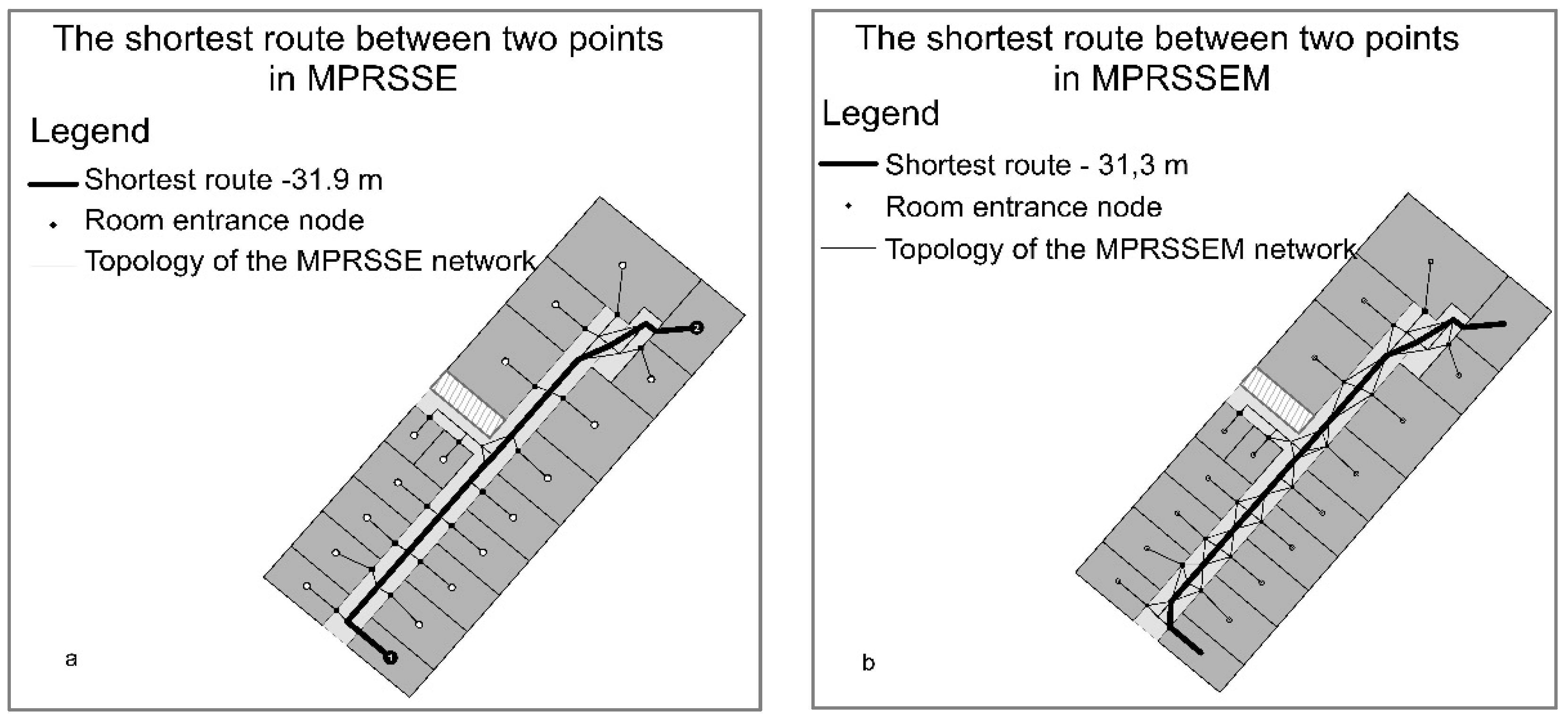
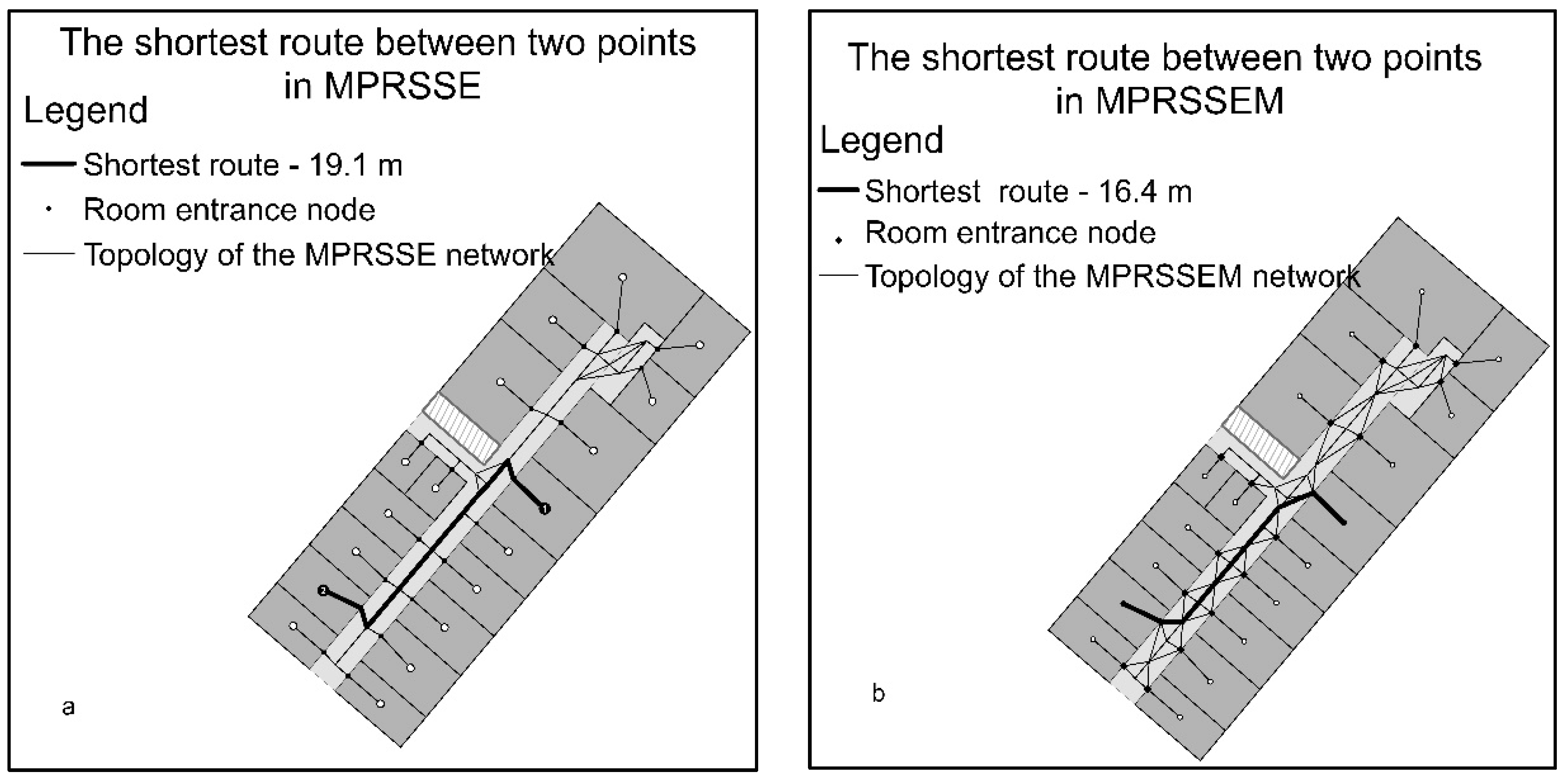
Indoor navigation models facilitate traffic in buildings. The MPRSSE and MPRSSEM models were used to generate paths between selected rooms. Two rooms that were most distant from one another were selected in the first example (Figure 6). Rooms that were located closer to each other were selected in the second example (Figure 7).
The above approaches produced different solutions. The MPRSS model would be useful if there were no partition walls on the side of the corridor. However, such solutions are rarely encountered in practice. The MPRSSE model is suitable for navigation despite the fact that (segment–entrance) and (segment–segment) edges form nearly straight or even acute angles along the routes. The MPRSSEM model supports the generation of routes that approximate natural paths. These routes do not have acute or straight angles. The MPRSSEM model generates the shortest routes.
4. Verification of the Proposed Methodology
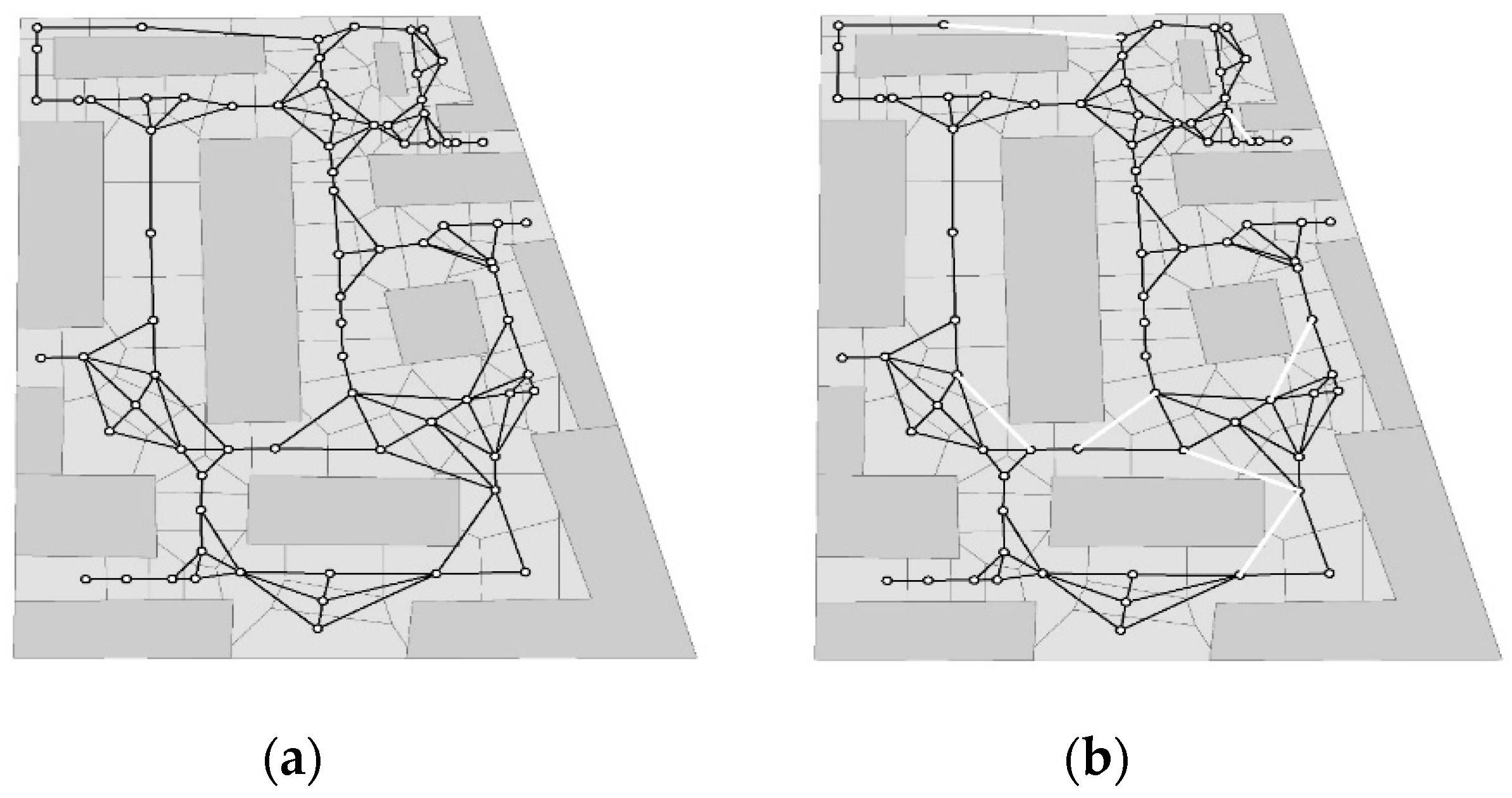
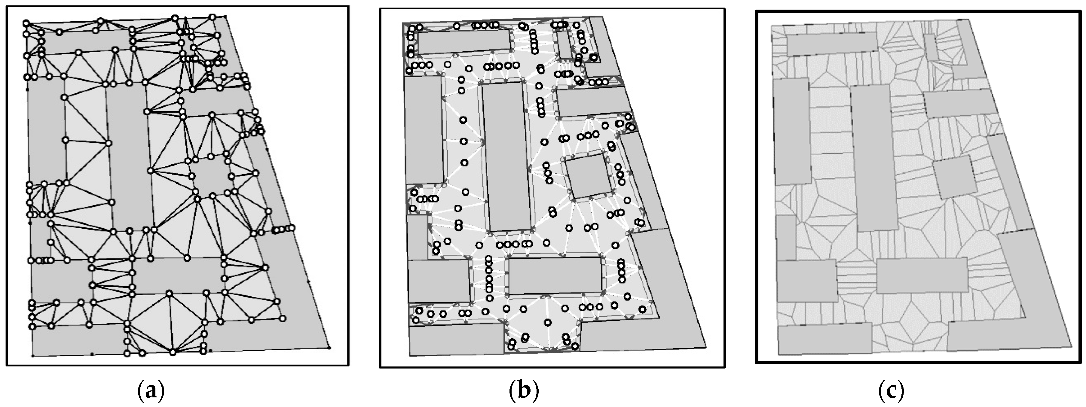
The proposed methodology was verified in a more extensive object presented by Lewandowicz and Lisowski [39]. Manually generated models of corridor space (Figure 8a), the models generated with the use of the NRSS method based on segment centroids (Figure 8b), and the models generated with the use of the MPRSS method based on midpoints (Figure 8c) are compared in Figure 9.
The manually generated network can be used for navigation, although it does not always run in the middle of the corridor (Figure 9a). The networks that were generated automatically with the use of NRSS and MPRSS methods are more extensive, and they occupy the middle of the corridor. The use of midpoints (PMid) as segment nodes in open and irregular spaces improves network quality. The MPRSS network has a less zigzagging course than that of the NRSS network.
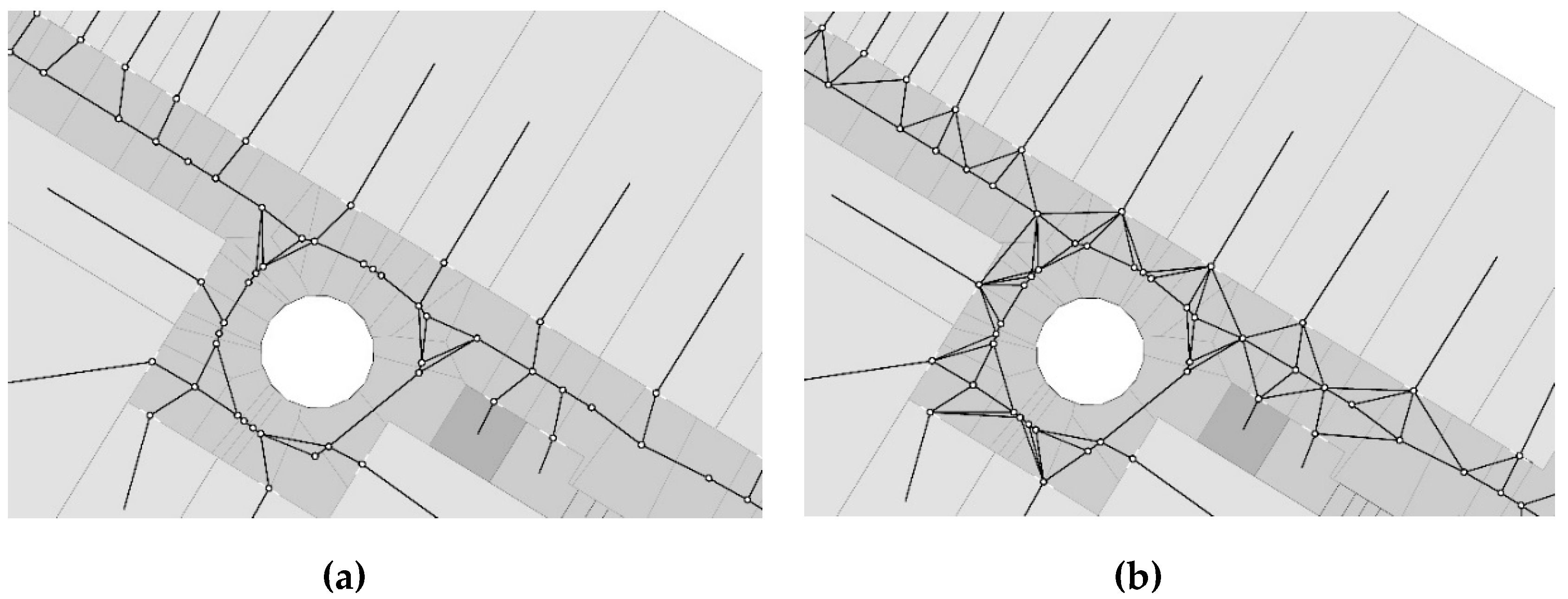
The presented data were also used to verify MPRSSE and MPRSSEM methods (Figure 9). The automatically generated models are more extensive, but the MPRSSEM model requires verification. In the model, several edges are located close to the walls, and some edges even intersect walls. These edges are found near convex corridor vertices, and they have to be eliminated. The elimination process does not compromise the network’s functionality. The resulting model can be used for navigation, and it generates routes with a minimal number of straight and acute angles.
Lewandowicz and Lisowski [39] observed that greater segmentation of irregular corridors increases zigzagging in the generated network model. The use of midpoints {PMid} eliminates zigzagging in the MPRSS model (Figure 10).
The adopted methodology was additionally verified in the space shown in Figure 11a, which can represent indoor premises or developed space. To generate the network automatically, open space was segmented based on the points representing the vertices of the main corridor elements. Selected fragments of TIN edges mapped to corridor space are presented in Figure 11b. The mapped edges were used to generate midpoints, {PMid}, (Figure 11c) and to segment corridor space (Figure 11d).
The network generated with the use of the MPRSS method based on segments of corridor space is presented in Figure 12a. The results were verified to reveal that two edges intersect the existing structures and five edges are positioned too closely to the existing structures (less than 0.55 m away). Any attempts to adjust the network by removing these seven edges lead to the loss of network continuity.
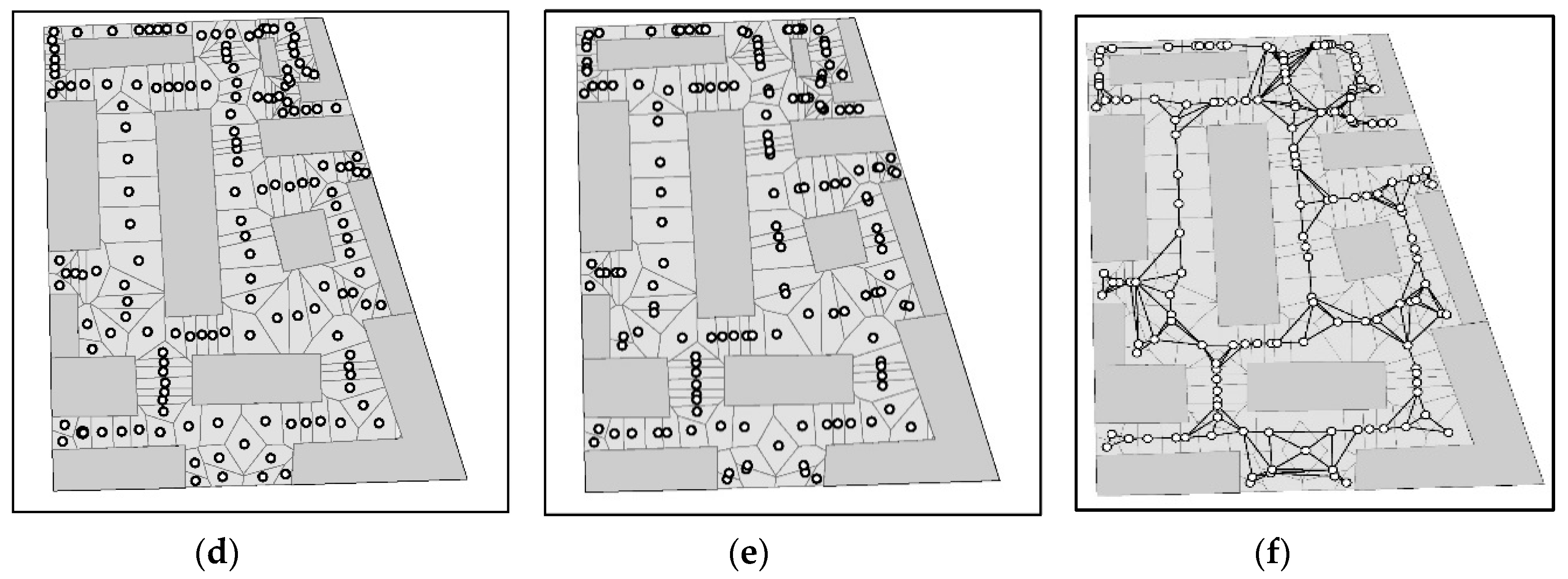
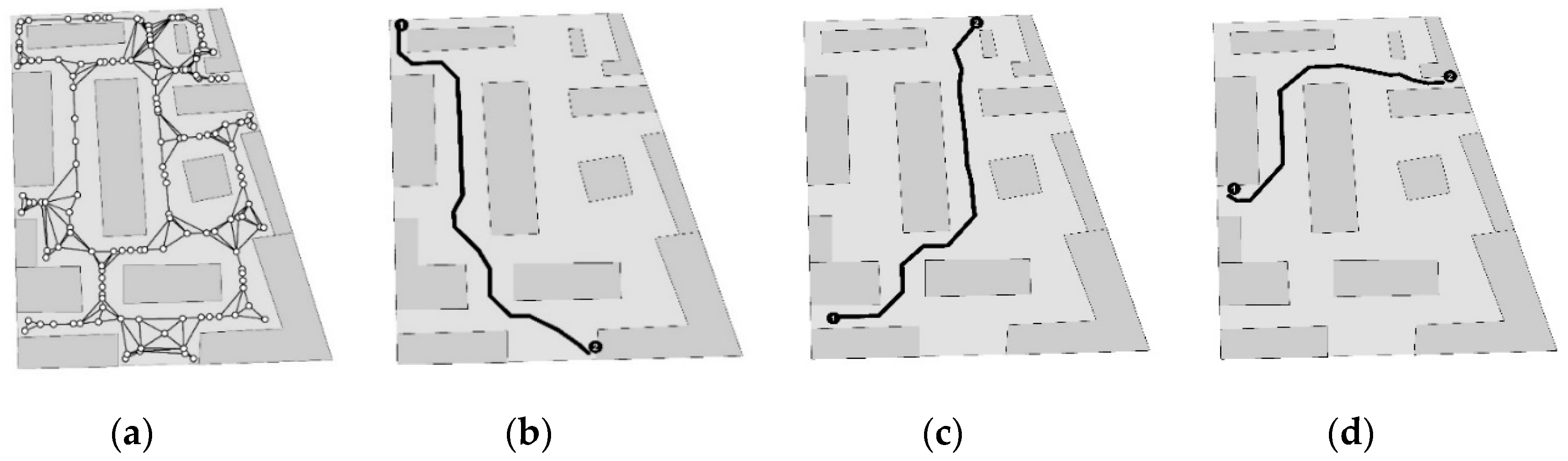
The verification process was repeated by increasing the number of corridor points for developing the TIN. In addition to vertices, two additional points were generated for every segment of corridor space (Figure 13). The number of segments increased, and the resulting network had a larger number of nodes and edges. The network runs centrally in corridor space and does not intersect the existing structures. The generated paths (Figure 14) validate the network’s functionality.
The use of midpoints, {PMid}, as segment nodes and their application for generating the MPRSS topological network produces better results. The MPRSS network model zigzags less than the model generated with the NRSS method based on segment centroids (N). MPRSSE and MPRSSEM models are extensions of the MPRSS model for indoor applications based on corridors, entrances, and rooms.
A larger set of points for generating TINs produces a higher number of PMid points and, consequently, a higher number of segments in corridor space. The generated network model has higher resolution, and it better fits the corridor axis. Unlike in the NRSS model, in this approach, higher resolution does not increase zigzagging [39].
The proposed method was successfully verified.
5. Conclusions
The main advantage of the proposed method for the automatic generation of a navigation network based on topological and semantic relations is its simplicity. The described solution relies on the MAT algorithm, which is widely used to construct indoor navigation models. The application of the midpoints of zigzagging lines minimizes network zigzagging. Therefore, the generated axis produces non-ambiguous solutions in geometrically regular spaces. Additional edges are generated at turns to develop routes resembling natural paths.
The MPRSS, MPRSSE, and MPRSSEM methods for generating route network models were presented based on a simple example in Section 3 and were successfully verified in a larger object (Section 4).
A manually generated model (Figure 8a), a model generated based on a previously described method [39], and a model generated with the use of the modified methodology (Figure 8c) are presented and compared in Figure 8. The results of this study indicate that automatic methods are more effective. In the modified method, midpoints were applied to denote segment nodes, which considerably improved the quality of the resulting network. The MPRSSE algorithm was modified to obtain the MPRSSEM algorithm, which supported the generation of more extensive network models with the shortest routes resembling natural paths.
In the future, the proposed method will be tested in other sites in multi-planar space. Corridor networks in buildings will be modeled in 3D for different user groups (people and robots, such as drones). The first reports describing such solutions have already been published [42].
Author Contributions
E.L. developed the research concept and the methodology and wrote the paper; P.L. generated the network based on centroids; P.F. generated the network based on midpoints from the topological data base.
Funding
This research was financed as part of a statutory research project of the Faculty of Geodesy, Geospatial and Civil Engineering of the University of Warmia and Mazury in Olsztyn, Poland, entitled “Geoinformation from the theoretical, analytical and practical perspective”, (No. 28.610.033300, timeline: 2017–2020).
Conflicts of Interest
The authors do not have any competing financial, professional, or personal interests.
References
- Hilsenbeck, S.; Bobkov, D.; Scroth, G.; Huitl, R.; Steinbach, E. Graph-based data fusion of pedometer and WiFi measurements for mobile indoor positioning. In Proceedings of the 2014 ACM International Joint Conference on Pervasive and Ubiquitous Computing, Seattle, WA, USA, 13–17 September 2014; pp. 147–158. [Google Scholar]
- Gao, S.; Krogstie, J.; Thingstad, T.; Tran, H. An Empirical Study of the Adoption of an Indoor Location-Based Service Finding Reading Rooms. Int. J. Technol. Hum. Interact. 2017, 13, 70–88. [Google Scholar] [CrossRef]
- Chartrand, G.; Zhang, P. A First Course in Graph Theory; Dover Publications: Mineola, NY, USA, 2012; p. 464. ISBN 100486483681. [Google Scholar]
- Lee, J. A spatial access-oriented implementation of a 3-D GIS topological data model for urban entities. Geoinformatica 2004, 8, 237–264. [Google Scholar] [CrossRef]
- Boeters, R.; Ohori, K.A.; Biljecki, F.; Zlatanova, S. Automatically enhancing CityGML LOD2 models with a corresponding indoor geometry. Int. J. Geogr. Inf. Sci. 2015, 29, 2248–2268. [Google Scholar] [CrossRef]
- Coleman, D.J.; Rajabifard, A.; Kolodziej, K.W. Expanding the SDI environment: Comparing current spatial data infrastructure with emerging indoor location-based services. Int. J. Dig. Earth 2016, 9, 629–647. [Google Scholar] [CrossRef]
- Teo, T.A.; Cho, K.H. BIM-oriented indoor network model for indoor and outdoor combined route planning. Adv. Eng. Inform. 2016, 30, 268–282. [Google Scholar] [CrossRef]
- Lee, J. A Three-Dimensional Navigable Data Model to Support Emergency Response in Microspatial Built-Environments. Ann. Assoc. Am. Geogr. 2007, 97, 512–529. [Google Scholar] [CrossRef]
- Lin, Z.; Xu, Z.; Hu, D.; Li, W. Hybrid Spatial Data Model for Indoor Space: Combined Topology and Grid. Int. J. Geo-Inf. 2017, 6, 343. [Google Scholar] [CrossRef]
- Cichociński, P. Modelowanie ewakuacji z budynków z wykorzystaniem analiz rastrowych (Modelling evacuation of buildings using raster analysis). Roczniki Geomatyki 2017, 4, 341–351. [Google Scholar]
- Cichociński, P. The concept of creating raster accessibility maps for multistorey buildings. In Proceedings of the 25th Anniversary Conference Geographic Information Systems Conference and Exhibition “GIS ODYSSEY 2018”, Perugia, Italy, 10–14 September 2018; pp. 111–119. [Google Scholar]
- Prinz, F.B.; Cern, J.H. Geometric abstractions using medial axis transformation. In University Libraries Carnegie Mellon University; Research Showcase @ C MU: Pittsburgh, PA, USA, 1988. [Google Scholar]
- Eppstein, D.; Erickson, J. Raising roofs, crashing cycles and playing pool. Applications of a Data Structure for Finding Pairwise Interactions. Discrete & Computational Geometry. Discret. Comput. Geom. 1999, 22, 569–592. [Google Scholar]
- Choi, J.; Lee, J. 3D Geo-Information Sciences; Springer: Berlin, Germany, 2009; pp. 283–299. [Google Scholar]
- Mortari, F.; Zlatanova, S.; Liu, L.; Clementini, E. Improved geometric network model (IGNM): A novel approach for deriving connectivity graphs for indoor navigation. ISPRS Ann. Photogramm. Remote Sens. Spat. Inf. Sci. 2014, II-4, 45–51. [Google Scholar] [CrossRef]
- Joan-Arinyo, R.; Pérez-Vidal, L.; Gargallo-Monllau, E. An adaptive algorithm to compute the medial axis transform of 2-d polygonal domains. In CAD Systems Development Tools and Methods; Roller, D., Brunet, P., Eds.; Springer: Berlin/Heidelberg, Germany, 1997; pp. 283–298. [Google Scholar]
- Aichholzer, O.D.; Alberts, D.; Aurenhammer, F.; Gärtner, B. A novel type of skeleton for polygons. J. Univers. Comput. Sci. 1995, 1, 752–761. [Google Scholar]
- Cheng, S.W.; Vigneron, A. Motorcycle Graphs and Straight Skeletons. Algorithmica 2007, 47, 159. [Google Scholar] [CrossRef]
- Tang, S.J.; Zhu, Q.; Wang, W.W.; Zhang, Y.T. Automatic topology derivation from IFC building model for in-door intelligent navigation. Remote Sens. Spat. Inf. Sci. 2015, XL-4/W5, 7–11. [Google Scholar] [CrossRef]
- Lewandowicz, E. 3D Cadastre, building 3D models with navigation network. In New challenges for land Information Systems in the Light of European Standards; Croatian Information Technology Society, GIS Forum: Zagreb, Croatia, 2015; pp. 28–38. ISBN 978-953-6129-47-8. [Google Scholar]
- Bogusławski, P.; Mahdjoubi, L.; Zverovich, V.; Fadli, F. Automated construction of variable density navigable networks in a 3D indoor environment for emergency response. Autom. Constr. 2016, 72, 115–128. [Google Scholar] [CrossRef] [Green Version]
- Bogusławski, P.; Mahdjoubi, L.; Zverovich, V.; Fadli, F. A dynamic approach for evacuees’ distribution and optimal routing in hazardous environments. Autom. Constr. 2018, 94, 11–21. [Google Scholar] [CrossRef]
- Lorenz, B.; Ohlbach, H.J.; Stoffel, E.P. A hybrid spatial model for representing indoor environments. In Web and Wireless Geographical Information Systems; Carswell, J.D., Tezuka, T., Eds.; Springer: Berlin, Germany, 2006; pp. 102–112. [Google Scholar]
- Stoffel, E.P.; Lorenz, B.; Ohlbach, H.J. Towards a semantic spatial model for pedestrian indoor navigation. In Advances in Conceptual Modeling–Foundations and Applications; Springer: Berlin/Heidelberg, Germany, 2007; pp. 328–337. [Google Scholar]
- Whiting, E.J. Geometric, Topological & Semantic Analysis of Multi—Building Floor Plan Data. Doctoral Dissertation, Massachusetts Institute of Technology, Cambridge, MA, USA, 2006. [Google Scholar]
- Zhu, Q.; Li, Y.; Xiong, Q.; Zlatanova, S.; Ding, Y.; Zhang, Y.; Zhou, Y. Indoor Multi-Dimensional Location GML and Its Application for Ubiquitous Indoor Location Services. ISPRS Int. J. Geo-Inf. 2016, 5, 220. [Google Scholar] [CrossRef]
- Xu, M.; Wei, S.; Zlatanova, S. An indoor navigation approach considering obstacles and space subdivision OF 2D PLAN. ISPRS—International Archives of the Photogrammetry. Remote Sens. Spat. Inf. Sci. 2016, XLI-B4, 339–346. [Google Scholar] [CrossRef]
- Krūminaitė, M. Space Subdivision for Indoor Navigation. Master’s Thesis, Delft University of Technology, Delft, The Netherlands, 2014. [Google Scholar]
- Ai, T.; Yang, S.K.M.; Li, J. Envelope generation and simplification of polylines using Delaunay triangulation. Int. J. Geogr. Inf. Sci. 2017, 3, 297–319. [Google Scholar] [CrossRef]
- Xu, M.; Hijazi, I.; Mebarki, A.; Meouche, R.E.; Abune’meh, M. Indoor guided evacuation: TIN for graph generation and crowd evacuation. Geom. Nat. Hazards Risk 2016. [Google Scholar] [CrossRef]
- Wallgrün, J.O. Autonomous Construction of Hierarchical Voronoi-Based Route Graph Representations. In Proceedings of the 4th International Conference on Spatial Cognition: Reasoning Action, Interaction, Proceeding SC’04, Frauenchiemsee, Germany, 11–13 October 2004; pp. 413–433. [Google Scholar] [CrossRef]
- Liu, L.; Zlatanova, S. An Approach for Indoor Path Computation among Obstacles that Considers User Dimension. ISPRS Int. J. Geo-Inf. 2015, 4, 2821–2841. [Google Scholar] [CrossRef] [Green Version]
- Liu, L.; Zlatanova, S. Towards a 3D Network Model for Indoor Navigation. In Urban Regional Data Management UDMS Annual; Taylor & Francis: London, UK, 2011; pp. 79–94. [Google Scholar]
- Yang, L.; Worboys, M.F. Generation of navigation graphs for indoor space. Int. J. Geogr. Inf. Sci. 2015, 29, 1737–1756. [Google Scholar] [CrossRef]
- Yang, L.; Sun, X.; Zhu, A.; Chi, T. A Multiple Ant Colony Optimization Algorithm for Indoor Room Optimal Spatial Allocation. ISPRS Int. J. Geo-Inf. 2017, 6, 161. [Google Scholar] [CrossRef]
- Staats, B.R.; Diakit, A.A.; Voute, R.L.; Zlatanova, S. Automatic generation of indoor navigable space using a point cloud and its scanner trajectory. ISPRS Ann. Photogramm. Remote Sens. Spat. Inf. Sci. 2017, IV-2/W4, 393–400. [Google Scholar] [CrossRef]
- Alattas, A.F.; Zlatanova, S.; Oosterom, P.V.; Chatzinikolaou, E.; Lemmen, Ch.; Li, K.J. Supporting Indoor Navigation Using Access Rights to Spaces Based on Combined Use of IndoorGML and LADM Models. Int. J. Geo-Inf. 2017, 6, 384. [Google Scholar] [CrossRef]
- Yan, J. Seamless Pedestrian Navigation in Indoor/Outdoor Large Spaces with No Clear Patterns for Movement. 3D Geoinformation. Available online: https://www.researchgate.net/profile/Jinjin_Yan2/project/Navigation-for-Indoor-Outdoor-Large-Spaces-with-No-Clear-Pattern-for-Movement/attachment/5bd8f1773843b0067541b0c4/AS:687584162365444@1540944247407/download/02+-+Jinjin+Yan+-+PhD+Research+Proposal.pdf?context=ProjectUpdatesLog (accessed on 30 November 2018).
- Lewandowicz, E.; Lisowski, P. Methodology to generate navigation models in building. J. Civ. Eng. Manag. 2018, 24, 619–629. [Google Scholar] [CrossRef]
- Lewandowicz, E.; Lisowski, P. Metodyka tworzenia modeli sieci drogowych w oparciu o dane katastralne (Methods of creating models of road networks based on cadastral data). Roczniki Geomatyki 2018, 4, 321342. [Google Scholar]
- Kodzik, A. Modernization of the Building Base to New Standards 2 and 3D (Modernizacja bazy lokali WGiGP do Nowych Standardów 2 i 3D). Master’s Thesis, University of Warmia and Mazury in Olsztyn, Olsztyn, Poland, 2014. [Google Scholar]
- Diakité, A.; Zlatanova, S. Spatial subdivision of complex indoor environments for 3D indoor navigation. Int. J. Geogr. Inf. Sci. 2018, 32, 213–235. [Google Scholar] [CrossRef]
Figure 1.
The analyzed object (a) and topological models of indoor navigation networks based on Node-Relation Structure (NRS) (corridor–room) (b) and Node-Relation Structure and Entrance (NRSE) (corridor–entrance–room) (c).
Figure 1.
The analyzed object (a) and topological models of indoor navigation networks based on Node-Relation Structure (NRS) (corridor–room) (b) and Node-Relation Structure and Entrance (NRSE) (corridor–entrance–room) (c).

Figure 2.
Theoretical background for generating object axes: (a) midpoints {PMid} of the zigzag line for mapping the object axis, (b) segmentation of object S into a set segments S→ {SS} based on the midpoints of the zigzag line and generation of the topology network: the middle line.
Figure 2.
Theoretical background for generating object axes: (a) midpoints {PMid} of the zigzag line for mapping the object axis, (b) segmentation of object S into a set segments S→ {SS} based on the midpoints of the zigzag line and generation of the topology network: the middle line.

Figure 3.
Segmentation of corridor space: (a) base points and Triangulated Irregular Network (TIN) edges, (b) zigzagging in corridor space and generation of midpoints {PMid}, (c) corridor segmentation with Voronoi diagrams (VDs) based on dataset {PMid}.
Figure 3.
Segmentation of corridor space: (a) base points and Triangulated Irregular Network (TIN) edges, (b) zigzagging in corridor space and generation of midpoints {PMid}, (c) corridor segmentation with Voronoi diagrams (VDs) based on dataset {PMid}.

Figure 4.
Network model in the corridor: (a) network generated based on topological relations in dataset {SS}, where midpoints {PMid} are the nodes, (b) differences in the location of midpoints {PMid} and segment centroids.
Figure 4.
Network model in the corridor: (a) network generated based on topological relations in dataset {SS}, where midpoints {PMid} are the nodes, (b) differences in the location of midpoints {PMid} and segment centroids.

Figure 5.
Three models of an indoor navigation network generated with the use of different methods: (a) Middle-Point Relation Structure Segment (MPRSS) network model; (b) Middle-Point Relation Structure Segment Entrance (MPRSSE) network model; (c) Middle-Point Relation Structure Segment Entrance Modification (MPRSSEM) network model.

Figure 6.
The shortest routes between two rooms in two models: (a) MPRSSE and (b) MPRSSEM.

Figure 7.
Another example of the shortest route between two rooms in two models: (a) MPRSSE and (b) MPRSSEM.
Figure 7.
Another example of the shortest route between two rooms in two models: (a) MPRSSE and (b) MPRSSEM.

Figure 8.
Network models generated with the use of different methods: (a) manually generated models [41], (b) models generated with the use of the NRSS method based on segment centroids [39], and (c) models generated with the use of the MPRSS method based on midpoints of the zigzag line in the corridor.

Figure 9.
Verification of the presented methodology: (a) a fragment of the MPRSSE model and (b) a fragment of the MPRSSEM model.
Figure 9.
Verification of the presented methodology: (a) a fragment of the MPRSSE model and (b) a fragment of the MPRSSEM model.

Figure 10.
Fragments of the network developed with the use of: (a) NRSS and (b) MPRSS (based on the input data applied by Lewandowicz and Lisowski [39]).
Figure 10.
Fragments of the network developed with the use of: (a) NRSS and (b) MPRSS (based on the input data applied by Lewandowicz and Lisowski [39]).

Figure 11.
Verification of the adopted methodology: (a) tested object, (b) zigzagging in corridor space based on TIN edges, (c) generation of midpoints, {PMid}, and segments of the zigzag line, and (d) segmentation of corridor space.
Figure 11.
Verification of the adopted methodology: (a) tested object, (b) zigzagging in corridor space based on TIN edges, (c) generation of midpoints, {PMid}, and segments of the zigzag line, and (d) segmentation of corridor space.

Figure 12.
Verification of the adopted methodology: (a) network generated by the MPRSS method and (b) elimination of edges that do not meet requirements.
Figure 12.
Verification of the adopted methodology: (a) network generated by the MPRSS method and (b) elimination of edges that do not meet requirements.

Figure 13.
Verification of the adopted methodology for a larger number of points in corridor space: (a) zigzagging in corridor space based on TIN edges, (b) generation of midpoints in segments of the zigzag line, (c) segmentation of corridor space, (d), location of segment centroids (N), (e) location of midpoints (PMid), and (f) model of corridor space based on midpoints.


Figure 14.
Paths generated in the MPRSS network model: (a) a network model generated with the MPRSS method for a larger number of base points in corridor space and (b–d) examples of paths generated between selected points.
Figure 14.
Paths generated in the MPRSS network model: (a) a network model generated with the MPRSS method for a larger number of base points in corridor space and (b–d) examples of paths generated between selected points.

© 2019 by the authors. Licensee MDPI, Basel, Switzerland. This article is an open access article distributed under the terms and conditions of the Creative Commons Attribution (CC BY) license (http://creativecommons.org/licenses/by/4.0/).
Share and Cite
MDPI and ACS Style
Lewandowicz, E.; Lisowski, P.; Flisek, P. A Modified Methodology for Generating Indoor Navigation Models. ISPRS Int. J. Geo-Inf. 2019, 8, 60. https://0-doi-org.brum.beds.ac.uk/10.3390/ijgi8020060
AMA Style
Lewandowicz E, Lisowski P, Flisek P. A Modified Methodology for Generating Indoor Navigation Models. ISPRS International Journal of Geo-Information. 2019; 8(2):60. https://0-doi-org.brum.beds.ac.uk/10.3390/ijgi8020060
Chicago/Turabian StyleLewandowicz, Elżbieta, Przemysław Lisowski, and Paweł Flisek. 2019. "A Modified Methodology for Generating Indoor Navigation Models" ISPRS International Journal of Geo-Information 8, no. 2: 60. https://0-doi-org.brum.beds.ac.uk/10.3390/ijgi8020060
Note that from the first issue of 2016, this journal uses article numbers instead of page numbers. See further details here.