Article

Diachronic Reconstruction and Visualization of Lost Cultural Heritage Sites

by
Pablo Rodríguez-Gonzálvez
1,*,
Ángel Guerra Campo
2,
Ángel L. Muñoz-Nieto
3,
Luis J. Sánchez-Aparicio
2 and
Diego González-Aguilera
3
1
Department of Mining Technology, Topography and Structures, Universidad de León, Avda. Astorga, s/n, 24401 Ponferrada (León), Spain
2
TIDOP Research Group, University of Salamanca, Avda. de los Hornos Caleros, 50, 05003 Ávila, Spain
3
Department of Cartographic and Land Engineering, University of Salamanca, Avda. de los Hornos Caleros, 50, 05003 Ávila, Spain
*
Author to whom correspondence should be addressed.
ISPRS Int. J. Geo-Inf. 2019, 8(2), 61; https://0-doi-org.brum.beds.ac.uk/10.3390/ijgi8020061
Submission received: 10 December 2018 / Revised: 23 January 2019 / Accepted: 27 January 2019 / Published: 29 January 2019
(This article belongs to the Special Issue Data Acquisition and Processing in Cultural Heritage)

Abstract

:
Cultural heritage (CH) documentation is essential for the study and promotion of CH assets/sites, and provides a way of transmitting knowledge about heritage to future generations. The integration of the fourth dimension into geospatial datasets enables generating a diachronic model of CH elements, namely, a set of three-dimensional (3D) models to represent their evolution in various historical phases. The enhanced four-dimensional (4D) modeling (3D plus time) pursues a better understanding of the CH scenario, enriching historical hypotheses as well as contributing to the conservation and decision-making process. Although new geomatic techniques have reduced the amount of fieldwork, when put together, the geometric and temporal dimensions imply the interpretation of heterogeneous historical information sources and their integration. However, this situation could reach a critical point when the study elements are no longer present. The main challenge is to harmonize the different historical and archaeological data sources that are available with the current remains in order to graphically rebuild and model the lost CH assets with a high degree of reliability. Moreover, 4D web visualization is a great way to disclose the CH information and cultural identity. Additionally, it will serve as a basis to perform simulations of possible future risks or changes that can happen during planned or hypothetical restoration processes. This paper aims to examine the study case of a diachronic reconstruction by means of a mobile laser system (MLS) and reverse modeling techniques for a lost urban CH element: the citadel or Alcázar gate of Ávila. Within this aim, the final model is evaluated in terms of the consistency of the historical sources to assess its suitability considering the constructive interpretations that are required to integrate heterogenous data sources. Moreover, geometric modeling is evaluated regarding the current remains and its surroundings. Finally, a web 4D viewer is presented for its dissemination and publicity. This paper is an extended and improved version of our paper that was published in the 2018 ISPRS Technical Commission II Symposium, Riva del Garda, Italy, 3–7 June 2018.

Graphical Abstract

1. Introduction

Geomatics techniques, which are also referred as geotechnologies, can be defined as a set of sensors and computer algorithms that allow the acquisition, modeling, and analysis of spatial features (individually or together) that are focused on knowledge generation for any level of detail and discipline that has to manage changes in space and/or time [1]. The increasing emergence of different geomatics techniques applied to cultural heritage (CH) modeling save countless fieldwork hours. However, models based on the current state of buildings and remains are commonly insufficient to explore and explain their historical background and evolution. This issue proves that the management and valorization of CH is a complex task in which scientists, developers, and final users aim to encourage cooperation and practice sharing.
Three-dimensional (3D) modeling and visualization techniques are being employed to document CH sites and assets that are threatened by natural influences (e.g., flooding, earthquakes, etc.) and/or human factors (e.g., mass tourism, pollution, etc.) [2,3]. Digital reconstruction implies the representation of the artefact or monument in its original state [4]. Within this aim, different geomatics techniques are being used to study the current state and the geometry of CH elements as a reference for modeling processes from airborne to ground level, such as laser scanning, photogrammetry, or global navigation satellite systems [5].
Due to the inherent complexity of CH elements, the use of complementary technologies [5,6,7,8,9] is usually required. Their fusion and hybridization are being studied, and in spite of the several approaches that are available [10], this issue still represents a hot topic for the scientific community [11]. Data fusion in CH is biased to the actual acquisition technologies [10], and is purpose-oriented to generate new data from the raw source. Moreover, the approaches are highly based on the data dimensionality [12,13]. The registered point clouds can be reconstructed to provide a parametric modeling of the historical building [14], or by means of non-parametric shapes [15]. However, the main problem remains when these CH elements only exist partially due to different reasons. In this case, 3D modeling or anastylosis approaches [16] are the best way to reconstruct the whole CH element [17,18], but require human expertise and knowledge about available historical documentation, as well as the verification of the suggested reconstruction through additional information, such as historical documents, images, records, etc. The expert and informal knowledge underlying the interpretation of historical data and its circumstances is vital for a correct reconstruction of the CH element [19].
Sources of historical information are really heterogeneous, encompassing texts, paintings, and engravings, to old photographs, maps, etc. [20]. Moreover, the 3D modeling process has to deal with the lack of objectivity and mutual coherence of historical data, due to errors in ancient surveys and/or conservations distortions [21]. Complementarily, archaeological data sources, which include excavated material, standing monuments, and inscribed records, among other sources, can be used as an objective reference to shape historical data sources. Last but not least, the alignment of components in a Cartesian space presents various challenges. It is not only difficult from a practical point of view, but it is complicated by the original shape of the object to be reconstructed only being known within a certain probability. To date, the virtual reconstruction of destroyed buildings has required a manual process that is based on full historical knowledge [22]. The reconstruction demands the consideration of expert knowledge and evaluation. The three-dimensional (3D) digitalization of the current remains serves a dual purpose: i) it could establish a transition to the missing parts of the diachronic reconstruction, and ii) it allows assessing the likelihood of the constructive hypotheses derived from the interpretation of the historical sources.
Once the 3D modeling has been carried out, a dynamic evolution of CH elements across different spatial scales is accessible, allowing the possibility of better understanding the present status of the CH asset/site according to its history [23]. This paper presents an approach to four-dimensional (4D) modeling and visualization through the diachronic reconstruction of lost cultural heritage sites. In the present case, the site is the Alcázar gate and its surroundings, which belongs to the Medieval Wall of Ávila (Spain), and was declared a Good of Cultural Interest by UNESCO (United Nations Educational, Scientific and Cultural Organization) in 1982.
The paper is organized as follows. After the introduction, Section 2 is focused on the materials and methods employed; Section 3 describes the study case, the experimental results obtained, and the diachronic viewer implementation. Finally, Section 4 summarizes the conclusions together with some future insights.

2. Materials and Methods

The present section describes both data sources for diachronic reconstruction—historical and geometrical, the methodology followed to obtain the 4D modeling; and finally, the considerations related to the 4D viewer implementation.

2.1. Historical Sources

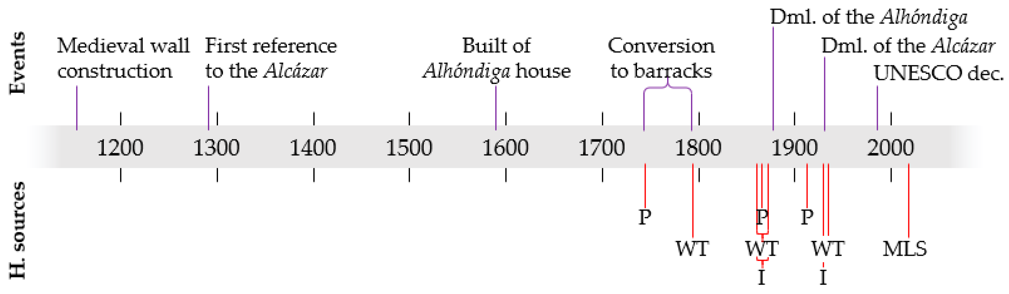
In this subsection, a description of the different historical sources that were used is presented. Through these sources, the CH transformations through time, including the evolution of the uses of the space and urban changes, are identified. To put this in context, Figure 1 shows a simplified timeline of the historical evolution of the study case (see Section 3.1 for further details), and the sources that were employed.
The Medieval Wall of Ávila has had different uses through its history. Most of them were related to defensive purposes. From c. 1291, a citadel (or Álcazar in Spanish) was built inside and attached to the southeast corner of the wall enclosure. Through its life, the citadel and near buildings suffered from several changes of use, as shown in Figure 1. It is likely that the demolishment of the citadel in 1930 was the largest transformation.
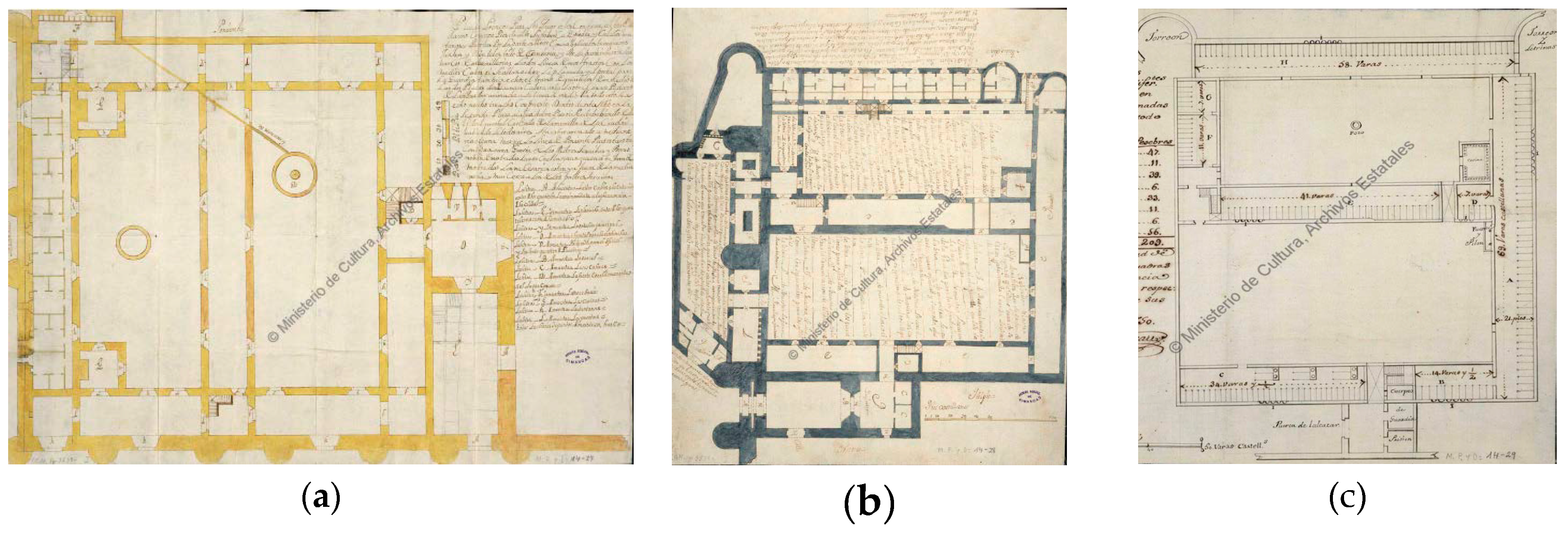
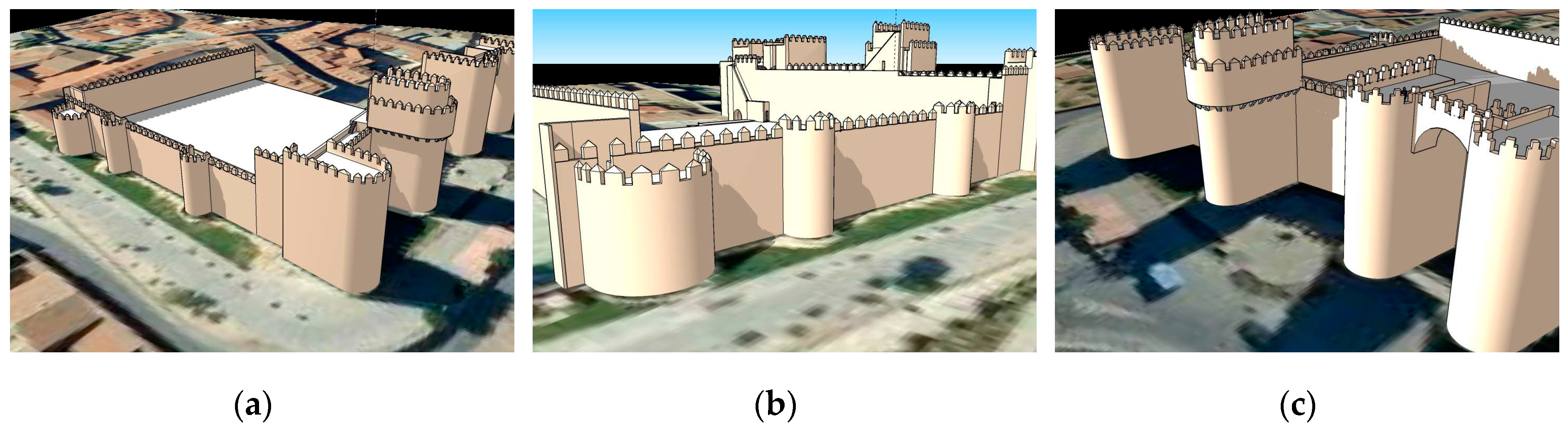
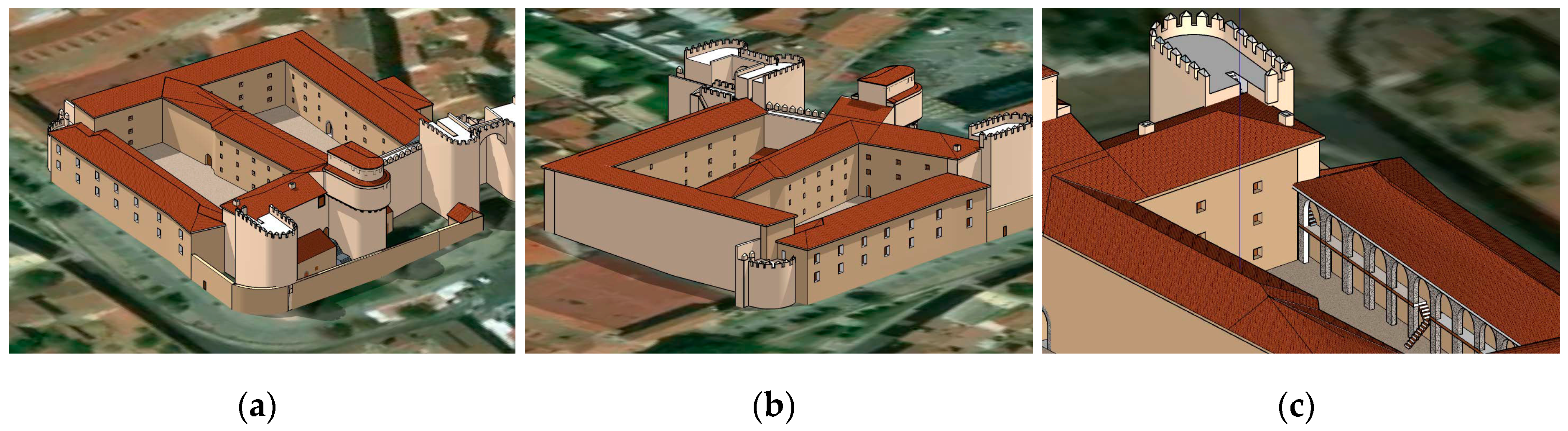
The most reliable historical sources of the citadel or Alcázar gate of Ávila were referred to in the plans made by Juan Gómez Parral in 1749 (Figure 2a,b), and in the plan of Pedro Moreau of 1750 (Figure 2c) related to the works of the conversion of the citadel into barracks. According to the information provided by these plans, a new plan design was built inside for the barracks with masonry arches. Also, a courtyard and a guard portal were created, as well as bedrooms and a gallery. We must highlight the opening of windows and the construction of an officers’ gallery. This latter room is of great importance since, as a consequence, two towers belonging to the Alcázar were demolished on the south canvas, and the height was reduced in six rows of the Polvorín tower. The Alcázar was again in a ruinous state according to a report dated in 1780, and the reforms that were carried out in 1806 and 1813 did not solve the serious problem of deterioration. From this moment, the 19th and 20th centuries lead to the total destruction of the Alcázar (1930).
Additionally, for the diachronic reconstruction assessment, two documents were used, despite their simplicity: a longitudinal profile of the street entrance to the Alcázar square, coming from the municipal architect Angel Cossín in 1864 (Ref. 134–53/27), and the plan made by the municipal architect Emilio González in 1911 (Ref. AHPAv. Ayto. 00070028).
Among all of the data sources that were used for the diachronic reconstruction, the best are those based on ancient drawings, which can provide a large amount of suitable information. However, their reliability is typically unknown. These documents present great contradictions among them, as well as with reality, especially the ones dated from the 18th century.
Other types of historical documents that were employed and analyzed included:
  • Historical photographs.
  • Maps.
  • Written testimonies.
The knowledge coming from these sources was added and weighted in the analysis by means of constraints regarding the buildings materials, constructive techniques, and geometric shape and boundary of those buildings that do not currently exist.
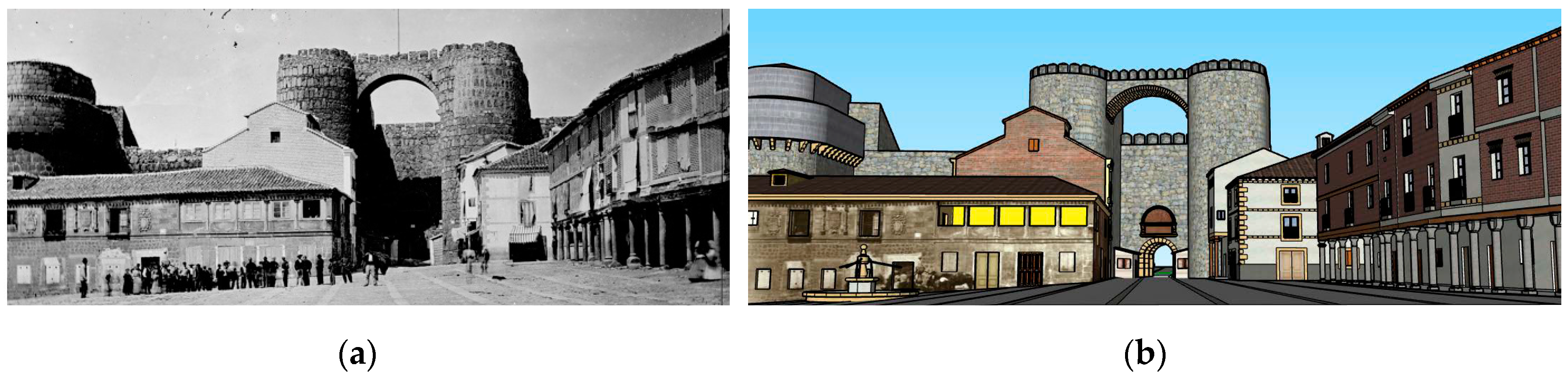
The role played by the different data sources depends on their antiquity, since intrinsic inconsistencies were shown, especially further back in time. In the case of the graphical material, old photographs are the most reliable, although they only cover a small temporal interval. These historical photographs used to be oblique, and thus enable the single-view reconstruction approach developed by [24,25], being able to extract geometric proportions, and even a partial reconstruction depending on the geometry of the shot.
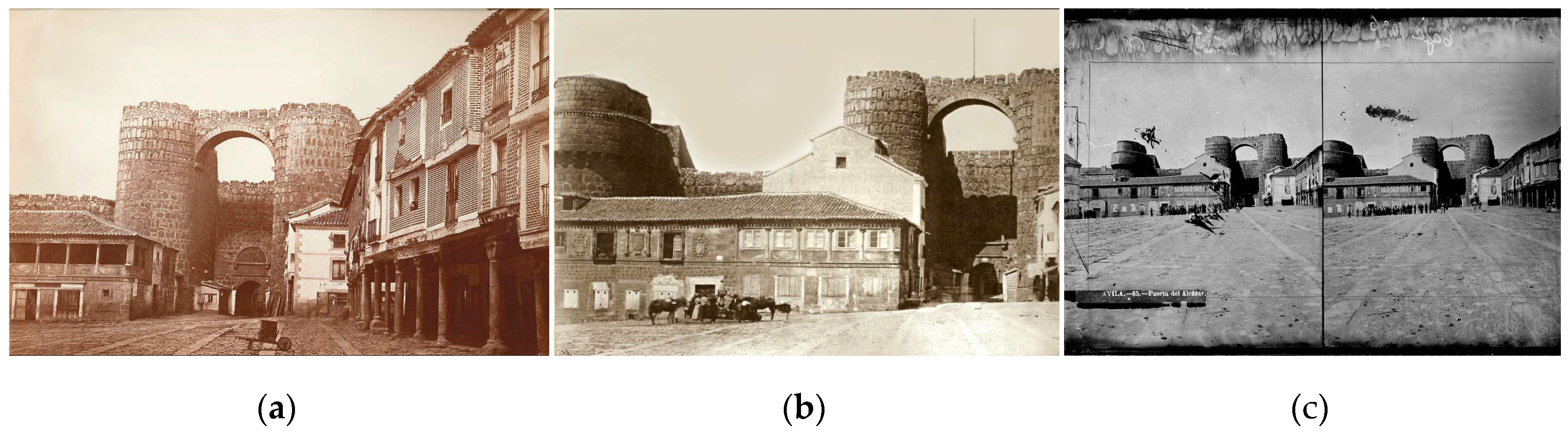
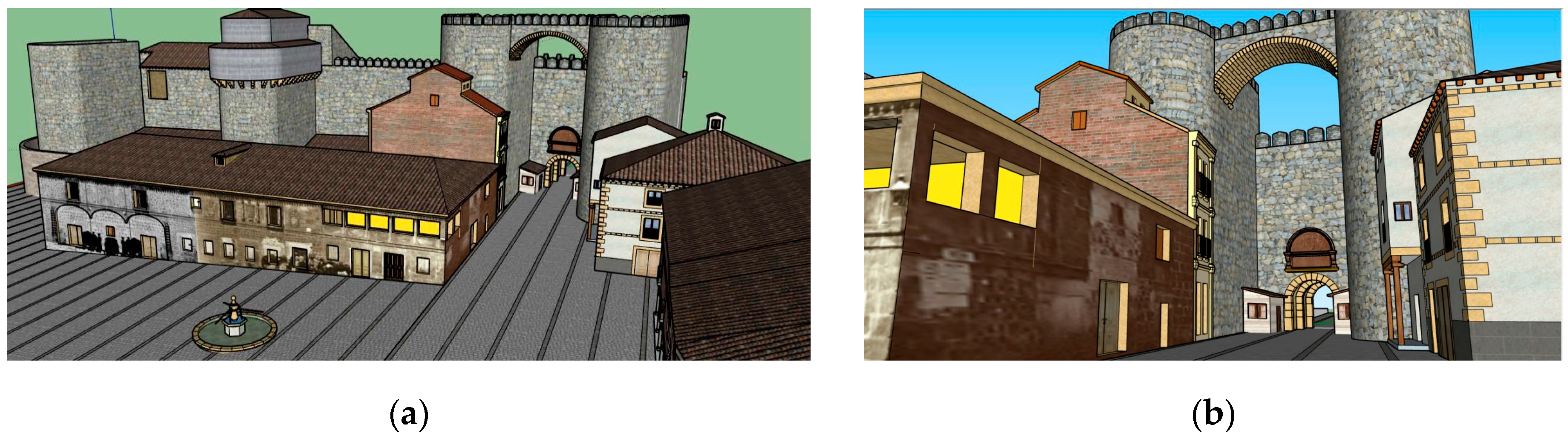
A total of three individual old images from c. 1860–1870 were considered (Figure 3). They cover a temporal keyframe, where some extramural buildings were modified. They played a key role along with the plans, since they provided objective information, in spite of the lack of scale or another direct information metric. There is no available information about the accuracy of these images.
The other graphical source was a city plan from c. 1865, whose use in the project is marginal. Its low resolution, due to the small scale (around 1:10,000), has limited the accurate location of the surroundings of extramural buildings, e.g., the circular fountain. As in the previous source, there is no available information about the accuracy of this source.
Finally, the written testimonies, which cover a temporal framework from c. 1860 to 1870, and an isolated one from c. 1935, describe the geometry of the citadel, the defensive system, or the transformation suffered by the asset. In spite of being non-graphical, they were used as a constraint source when there was not graphical information available, or there were discrepancies between the graphical information, the constructive hypothesis, and/or the current remains.

2.2. Geomatics Techniques

Geomatics techniques and technologies have long played an important role in CH documentation and preservation [26,27,28,29]. They range from red–green–blue (RGB) and multispectral cameras to terrestrial laser scanners (TLS), airborne laser scanners (ALS), drones [30], and even mobile laser systems (MLS) [31]. Due to the nature of the study case (see Section 3.1), which is placed in an urban center, and its significant extension, the MLS is employed as a data source for recording the present state of the current remains. The suitability of MLS for the documentation and dissemination of CH is described in [32,33]. The technical specifications of the employed MLS are listed in Table 1. This system is composed of two light detection and ranging (LiDAR) sensors, four RGB cameras, and an Applanix POS LV 520 Inertial Navigation System (INS). The system is configured to take 500,000 points per second with a scan frequency of 200 Hz. The maximum range of the sensors is 200 m, with a precision of eight mm (one sigma) and permission to obtain up to four echoes of the signal and the intensity reflected by the objects at a 1550-nm wavelength. The MLS was boarded in a car, achieving speeds of up to 40 km/h in the data acquisition.
The MLS measurement process is not completely straightforward, and the final results will be constrained by the initial planning phase. MLS calibration uncertainty is directly propagated to the recorded object, which could cause a lack of overlapping between scans of the same scene acquired from different trajectories. The completeness of the final scenario is directly linked with the complexity of the CH site, which is usually high, as well as where the vehicle is allowed to go. Regarding the final precision, the dependence of MLS on the GNSS (Global Navigation Satellite System) signal will cause a precision degradation in scenarios with weak satellite geometry, such as narrow streets in the case of urban CH assets [32]. Besides, the precision of the acquired point cloud is related to the laser angle of incidence [34]. All of these issues imply a constant control of the scanning process and a rigorous planning phase. An alternative geomatic technique, the portable mobile mapping systems [35,36], will dismiss some of the previously mentioned constraints (such as completion and GNSS dependence).

2.3. 4D Reconstruction Methodology

According to [10], when planning a 3D documentation of a heritage object, it is necessary to observe the data fusion requirements, the scene/object characteristics, and the availability of the equipment and sensors. The main requirements for data fusion are: accuracy level, radiometry importance, documentation purpose, and final use of the 3D products. The accuracy level enables ensuring that accuracy and details are preserved when mixing several data. A recommended approach is based on considering the geometric resolution differences among datasets, defining several accuracy levels, and adapting the level of information of each artefact to its acquisition methodology. However, in the present case study, the datasets that were employed not only have different spatial resolution, but some of them have unknown specifications. So, it was not possible to apply the proposed data fusion pipeline. As a result, the final application of the 4D model was used as a main constraint to providing a diachronic model with a high degree of reliability.
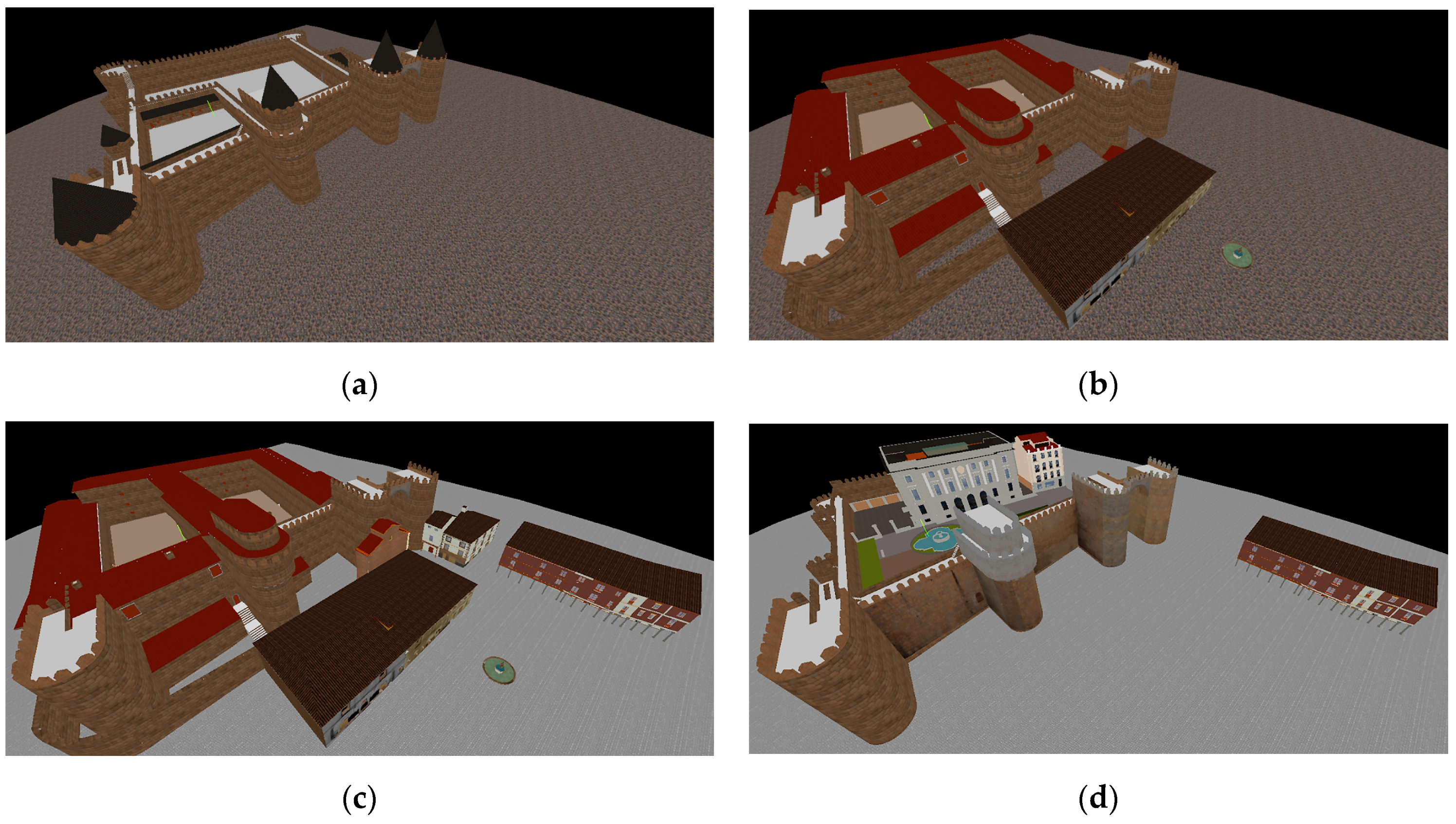
From the different geometrical and historical data sources stated previously, the reconstruction process was divided in the following steps:
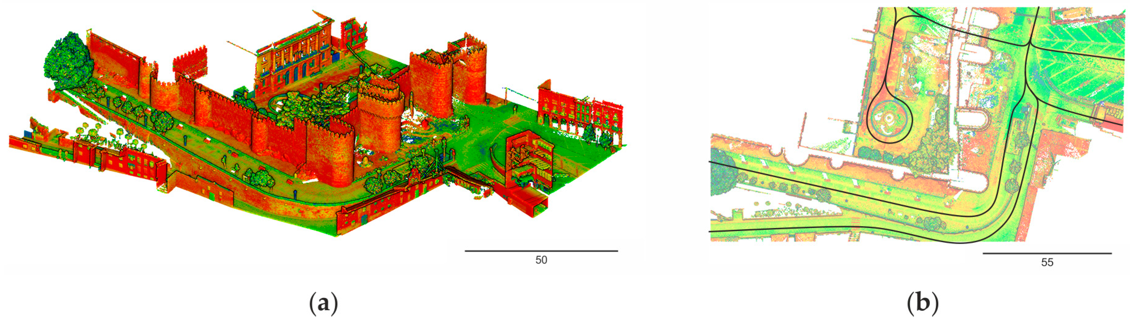
  • 3D recording of the current remains of the Alcázar gate by means of a MLS.
  • Reverse modeling of the current state of the Alcázar gate and its intramural and extramural sections.
  • Diachronic reconstruction or 4D modeling of the Alcázar gate based on the historical documents for two different temporal intervals.
  • Diachronic reconstruction or 4D modeling of the extramural and intramural buildings of the Alcázar gate prior to their demolishment.
Obtaining a 3D recording of the current state by MLS requires an initial planning phase, where not only the aimed spatial resolution and average distance to the study object (constrained by the transit area) is set, but also the trajectory and GNSS availability, since the precision properties are highly dependent on them. Finally, details such as the scanning day and hour will condition the completeness, since this CH asset is located in a heavily trafficked area.
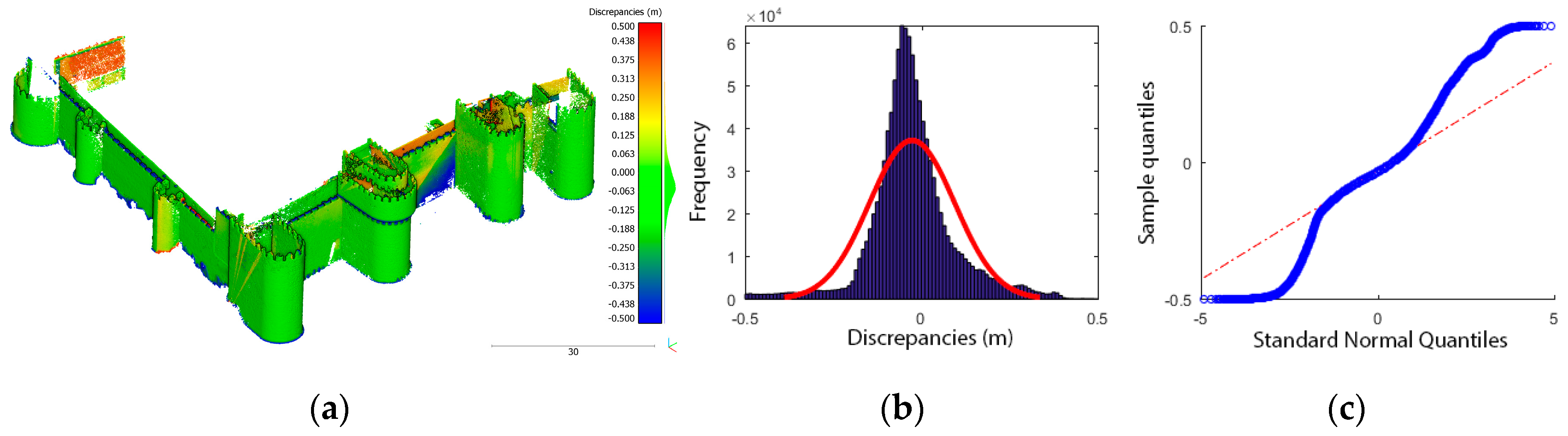
The reconstruction of the current state will provide the basis for the anastylosis process, and will also be essential to anchoring the plausible reconstruction of the lost building elements. This first phase required the classical steps of 3D modeling: filtering the non-desirable elements of the point cloud (e.g., pedestrians, cars, etc.) and extracting the geometrical data of the study area. The extraction of the basic primitives was done on the basis of cross-sections. This process involves a generalization operation and a loss of accuracy due to the idealization of regular shapes (i.e., planes, cylinders, etc.) [37]. The addition of certain constraints, such as the parallelism of the façades with the plumb line, also contributed to idealization and a loss of reliability. The fidelity of the 3D reconstruction is addressed more deeply in Section 3.4. For an in-depth description of the methodological procedure and a description of the different phases of multi-source data integration, please refer to [38].

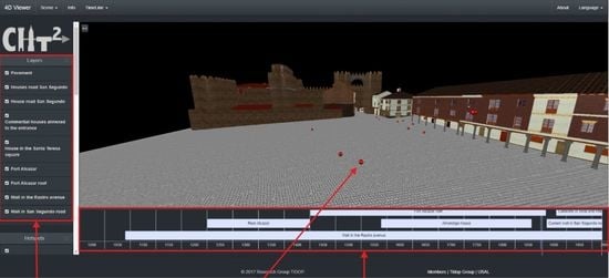
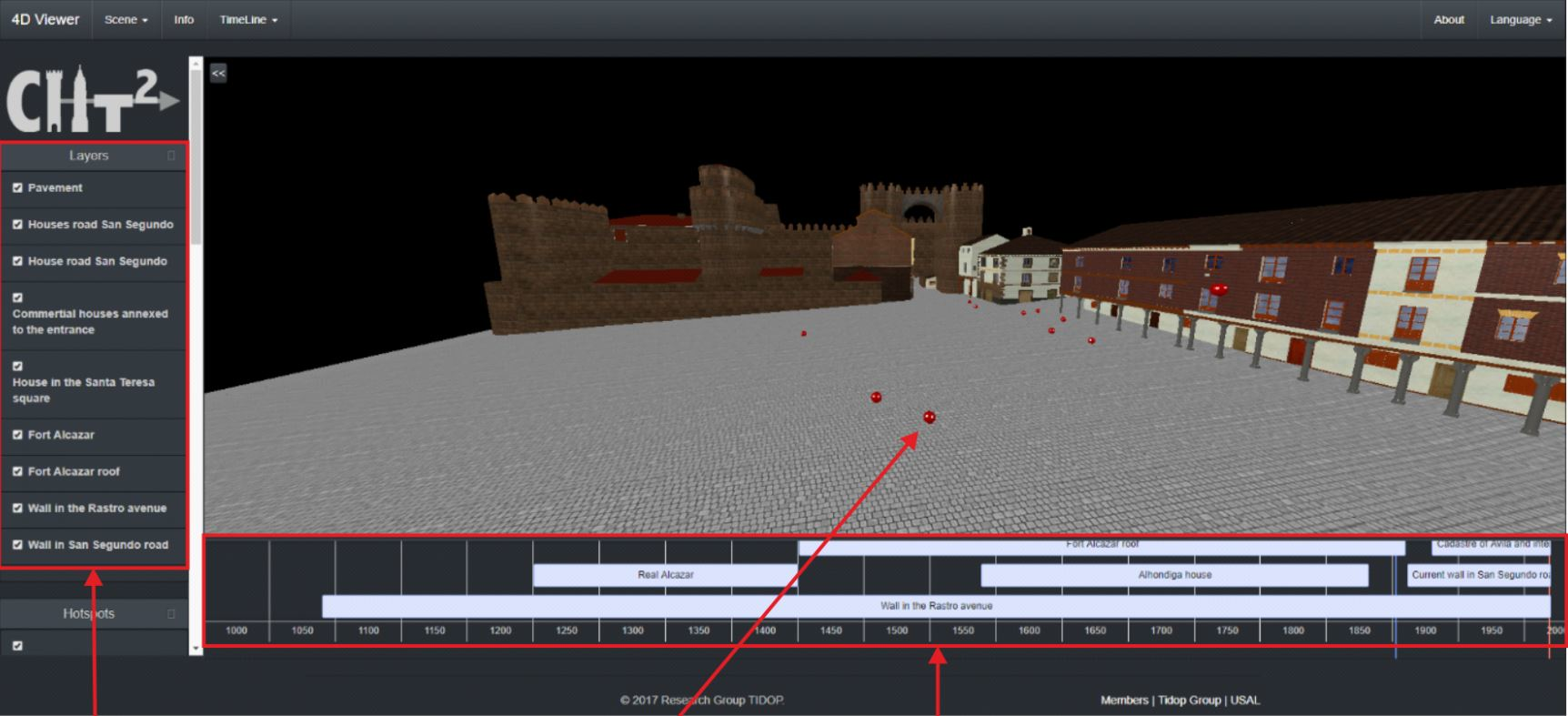
2.4. 4D Visualization Methodology

Visualization and analysis use to be the final steps in geomatics. The management of different information sources, such as stratigraphic and mensiochronologic analysis or diachronic reconstructions, among others, require the design of specific solutions to allow a metric and quality approach to the scientific analysis of the CH assets/sites, improving the benefits of an ordinary visualization [39]. The integration of 3D models in a timeline or a 4D environment requires the development of an ad hoc software for visualizing and managing large digital datasets in real-time. With the development of the JavaScript API Web Graphics Library (WebGL), Beaverton, OR, USA, the possibility of visualizing and consulting 3D models through the use of a web browser has opened new possibilities in CH [40].
Under this basis, there are several open-source 3D web viewers that are able to deal with complex 3D environments. Inside this group, it is possible to highlight the viewer 3DHOP (3D Heritage Online Presenter) developed by the Visual Computing Lab of ISTI-CNR (Information Science and Technologies of the Italian National Research Council) [41]. This viewer, which is based on the WebGL engine, is able to deal with 3D models by means of meshes that are loaded following a multiresolution approach. This viewer is highlighted due to its easy combination with other web-page tools, allowing the integration of layers or even the linking of information through the use of hotspots [41]. In this framework, the comparison between two models is done by means of integrated links. Another interesting open-source solution for rendering complex 3D scenarios is the framework that Potree developed by the Institute of Computer Graphics and Algorithms [42]. This tool, based on the WebGL technology, enables rendering point clouds through the use of an octree visualization system [42]. Potree is highlighted due to its capacity for loading large point clouds datasets, making measurements (i.e., distances, areas, and volumes), and including annotations (hotspots). In line with the 3DHOP tool, Potree provides the possibility of comparing several models through the use of integrated links. Within commercial software, it is worth mentioning ArcGis CityEngine [43]. This tool is specially designed for urban purposes, accepting the simultaneous comparison of two 3D models made in different epochs (i.e., the evolution of a city through time) using a scrollbar. However, none of these platforms allow a 4D navigation where the user can navigate through a timeline and dynamically consult the 3D appearance of an architectural scenario over time.
Four-dimensional data visualization can be stated as the logical evolution of 3D dataset visualization in which time-varying visual products can be achieved. This evolution can be explained because time aspects become increasingly important in different application fields, whether analyzing or visualizing temporal changes due to anthropic activities, or simply mapping the deterioration caused by the passage of time. The advantages that 4D visualization offer are [38]: (i) a non-destructive way for archaeologists, art historians, and other scholars to analyze and monitor CH sites, monuments, and objects through time; (ii) the user’s interaction with objects and information from the past to the present; and (iii) the possibility of building complex virtual scenarios with digitally reconstructed non-existent artefacts within their contextual background, to recreate either a real area or a non-existent environment based on a conceptual hypothesis, where the user can navigate in an interactive way.
Four-dimensional (4D) viewer implementation requires the initial task of requirements analysis; this has been grouped into functionals and non-functionals analyses, which define the specific system behavior and the criteria to judge the system operation, respectively. The functional requirements that are defined are:
  • It must be possible to visualize data in a three-dimensional environment in known file formats.
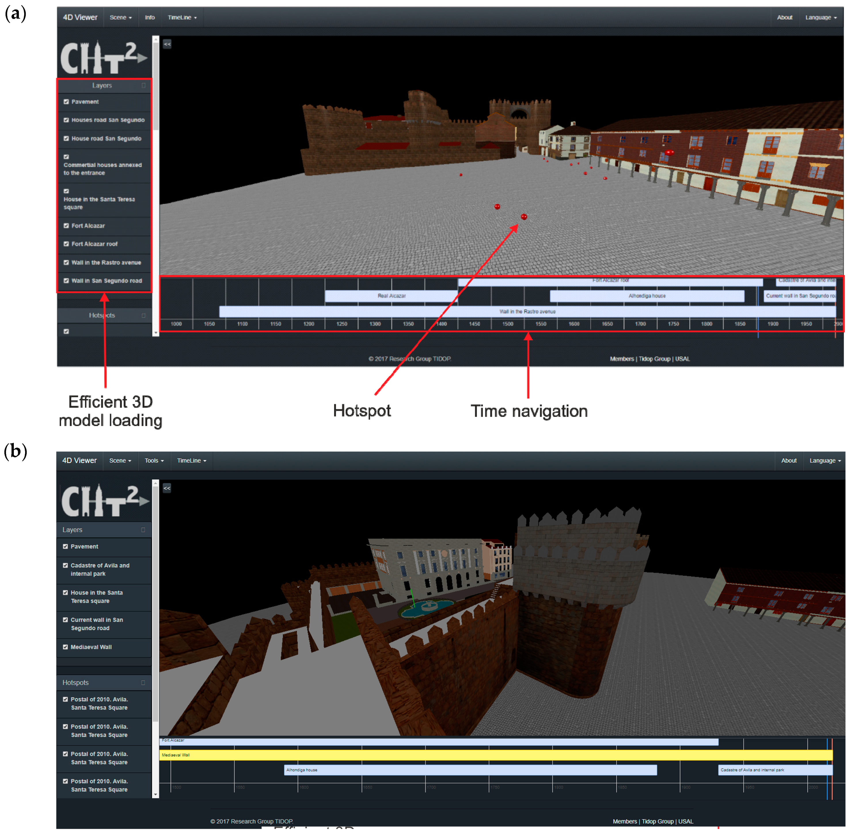
  • The data of each file must be organized through a system of layers, which can be displayed and hidden easily.
  • A dedicated tool that helps see the data in different epochs of history, namely the fourth dimension, must be available.
  • 3D models may have hotspots to provide additional information about the element selected.
  • The viewer must be a web application in order to be consulted by different types of users and experts through the Internet.
In order to fulfill all the functional requirements previously shown, the render engine WebGL was chosen. This API enables rendering a 3D environment through the combination of HTML-5 and JavaScript codes. Among the different advantages that this library can offer, highlights include [40]:
  • The capacity of rendering dynamically 3D environments.
  • Hardware acceleration to render a complex environment in a quicker way.
  • Compatibility with most of the desktop and mobile web browsers.
However, the main limitation of this library is the absence of a format for loading 3D models (such as .obj or .ply), as well as the absence of events (e.g., rendering actions or camera events) that allow the creation of interactive scenes. Taking this into consideration, the WebGL rendering engine was implemented through the JavaScript library Threejs (
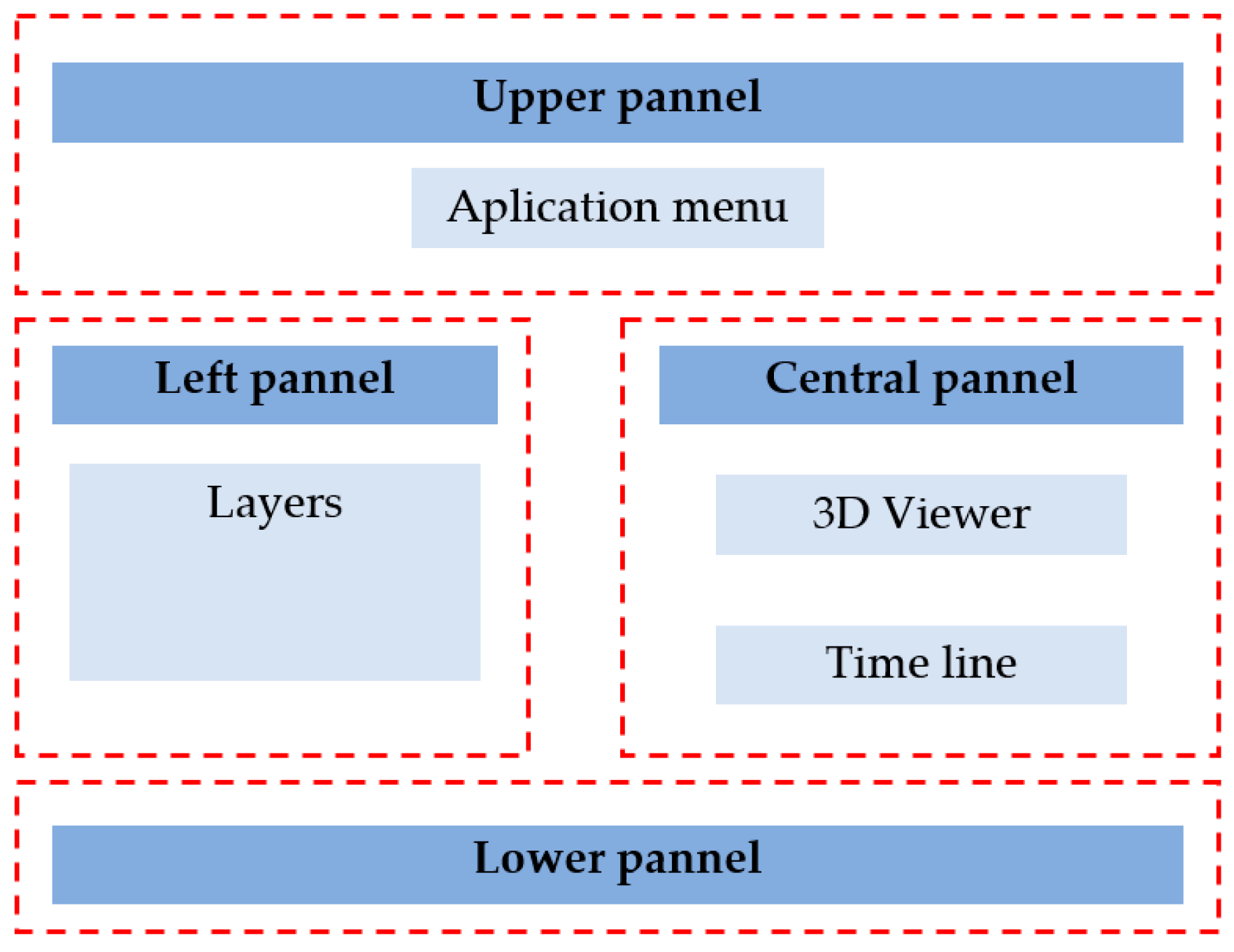
https://threejs.org/). This open-source library includes events for the camera, illumination patterns, and the ability of rendering models. Another important feature of this library is the possibility of using the Graphical Programming Unit (GPU) due to the weight of the different 4D models. As a final advantage, it works easily with other JavaScript libraries. This render engine was complemented by HTML-5, CSS-3, JSON, and standard JavaScript codes through the use of the Bootstrap environment for the interface (https://getbootstrap.com/), and the JavaScript library React (https://reactjs.org/) for the creation of classes. All of these components were implemented following a single page application approach (SPA). This programming strategy, the SPA, enables working in a unique page, avoiding the need to reload the application every time the user executes a function (e.g., loading a different epoch or taking measurements). To this end, the SPA follows a twofold strategy that firstly downloads the main HTML, CSS, and JavaScript codes into the client (user), and then progressively executes the different actions demanded by the user (such as the rotation of the scene or the loading of different scenes) by means of an AJAX protocol (Asynchronous Javascript and XML). In parallel to this, and in order to make the application scalable for further improvements, all of the libraries and frameworks were compiled inside the open source environment Visual Studio Code (https://code.visualstudio.com/) with the help of the library WebPack (https://webpack.js.org/). As a result, it was possible to create an application with the following architecture (Figure 4).
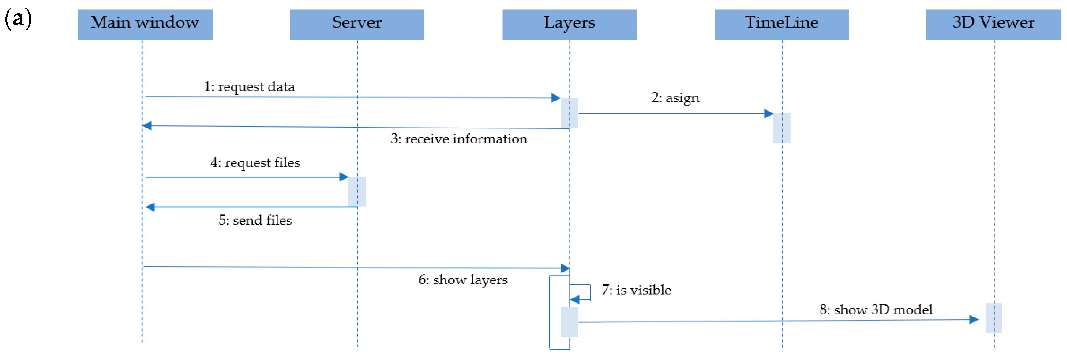
The combination of the previously shown libraries and frameworks enables the visualization of complex 3D scenes by means of a web browser. In order to provide the 4D dimension to the model, the open-source library visjs (http://visjs.org/docs/timeline/) was used. This library enables creating, editing, and deleting items (in our case 3D models) according to a specific date or range of dates. Under these bases, the following sequential process was used in order to visualize the different models along the timeline (Figure 5).
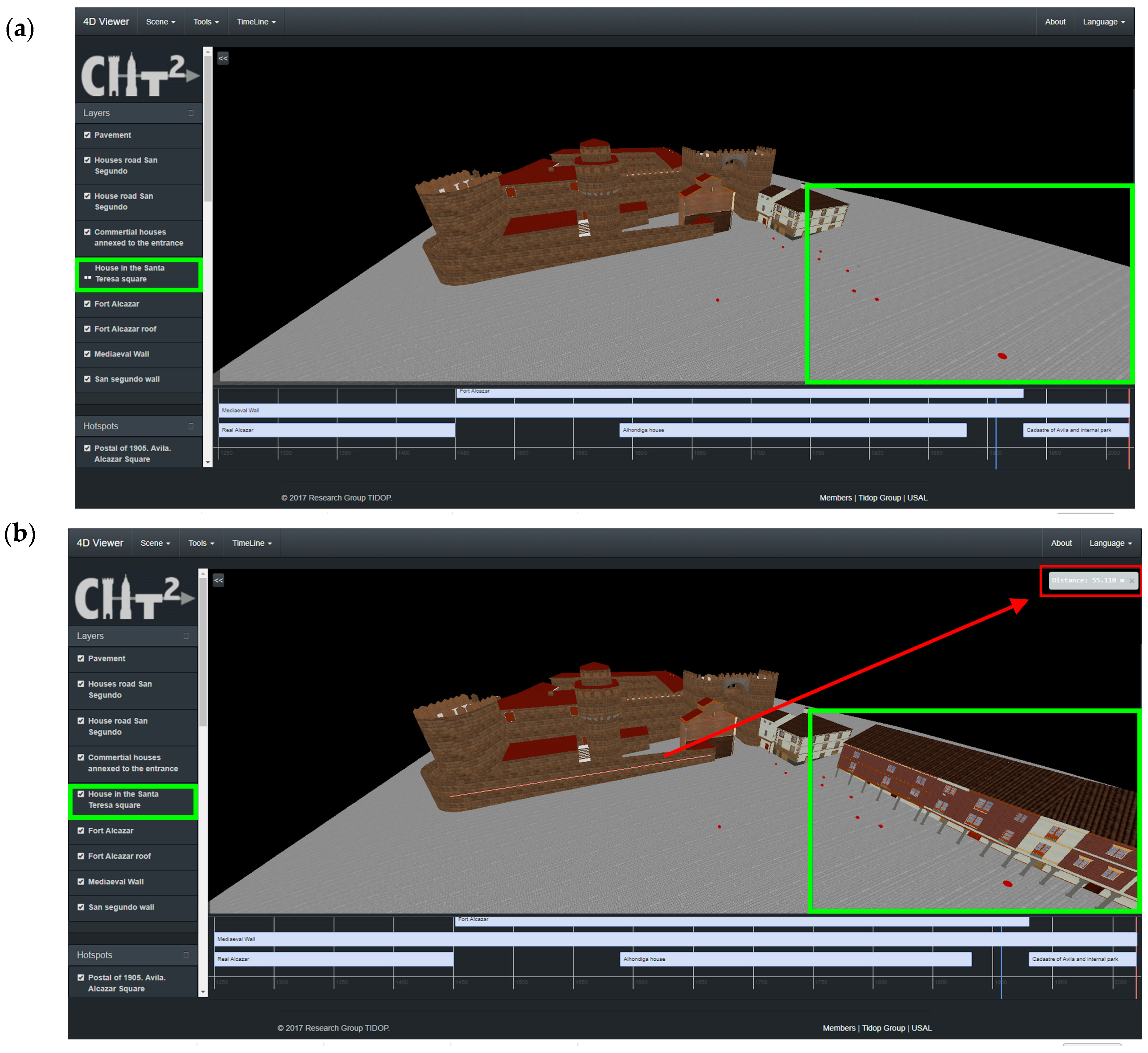
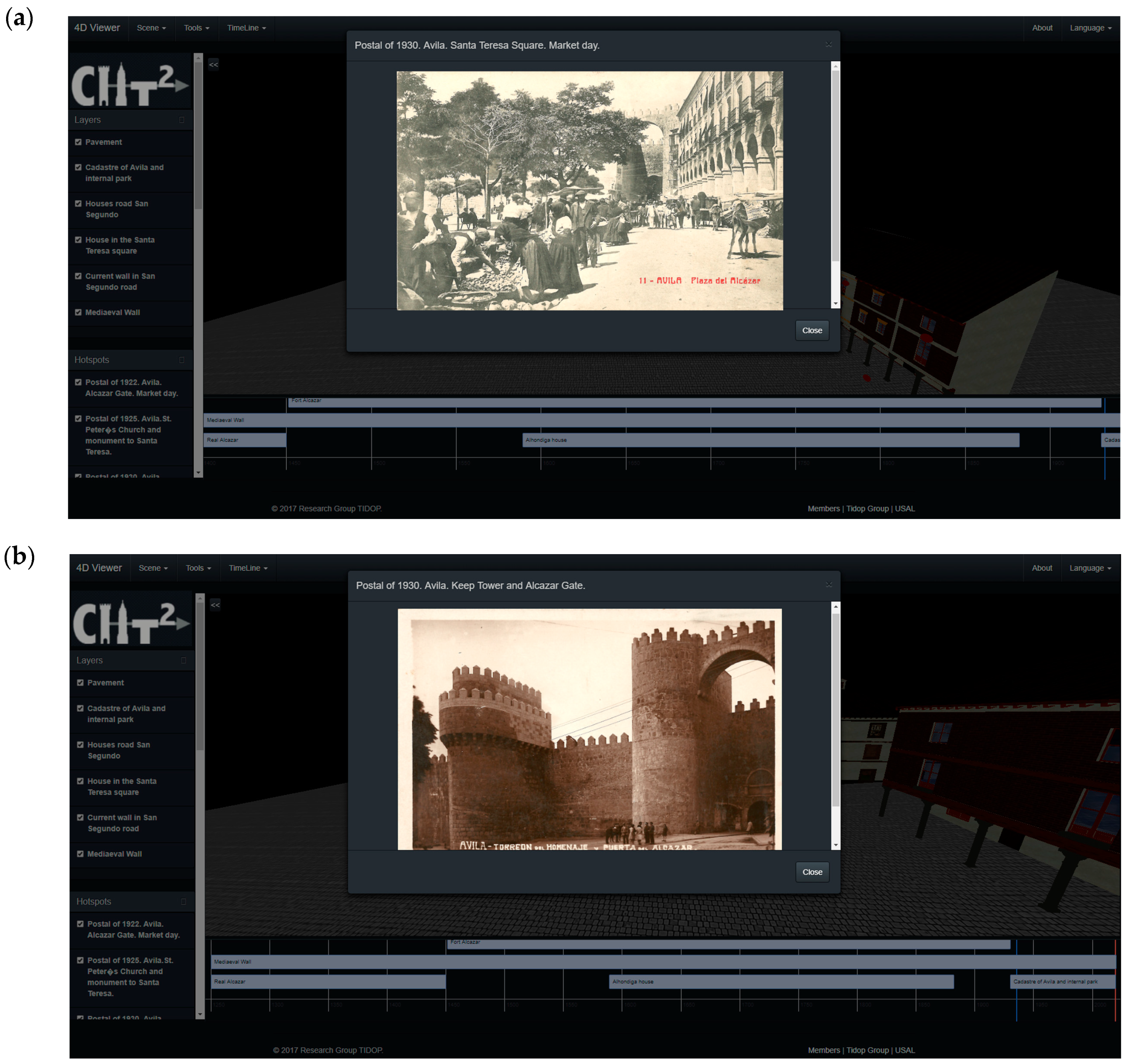
Apart from the main architecture of the application, two additional tools were included, namely: (i) a distance measuring tool, and (ii) hotspots. On the one hand, the distance measuring tool was implemented with the aim of exploiting the metric capabilities of the diachronic reconstructions. On the other hand, the hotspot viewer was designed with the purpose of showing non-geometrical data such as historical photographs, postcards, and historical/didactical texts. This information appears in the form of an emergent window, which is also called a modal window. This window is loaded in an asynchronous way by means of an AJAX protocol that is executed when the user clicks on the hotspot. In the same way as the 3D models, this information appears in accordance with the date chosen by the user in the timeline.
According to the information exposed above, the application is able to deal with two types of data: (i) geometrical data coming for the 3D models obtained during the diachronic reconstruction, and (ii) non-geometrical data, such as historical photographs or texts, by means of the use of hotspots and modal windows. On the one hand, the geometrical data is uploaded to the viewer in .obj format. Then, the data is linked to the layer and timeline layouts by means of a JSON (JavaScript Object Notation) file. This file has the following main fields: (i) name of the layer; (ii) start date; (iii) end date; and (iv) path of the file. Additionally, to these fields, the JSON file includes information about the visibility of the 3D model in the layer and timeline bars. On the other hand, the non-geometrical data is uploaded to the viewer through the use of a HTML-5 modal page, linking this information with the timeline and the 3D environment through the use of a JSON file. This JSON file has the same fields as those defined for the geometrical data.

3. Results

3.1. Case Study

The Medieval Wall of Avila is the universal symbol and the most outstanding monument of the city of Ávila (Spain). Its importance derives from being the best-preserved medieval walled enclosure in Spain. The walls are a very important factor in shaping the urban planning of the city, and historically, they have participated in the distribution of urban space among the various social groups that have inhabited Ávila. In particular, the Alcázar gate is the most solemn element of the entire wall. This gate is constituted by two large towers joined by a bridge (which is a unique and a singular element between the European walls), which reinforces the defence of access.
There is no record of an exact date of the beginning of the construction of the Alcázar gate (or citadel). However, the oldest graphic document that can be found is a painting belonging to the painter Anton Van der Wyngaerde (1570). The Alcázar gate was restored and modified, and already in the 18th century, the Alcázar gate definitely lost its status as a fortress and went through different uses. In 1749, with the cession of Fernando VI, the Alcázar gate became a fortress, and numerous reforms, such as opening windows and even demolishing two cubes of the wall and reducing the height of another, were realized.
In the outer walls of the Alcázar gate, patrimonial elements were found that today no longer exist, such as the house of the Alhóndiga, which was built in 1590, and was formerly an establishment where people sold, bought, and even stored grain. This building throughout its history had different uses, including as a cereal market, jail of notables, and police headquarters, before its demolition in 1882.
The 3D point cloud of the current remains by MLS (Table 1) was acquired with a spatial resolution of 60 mm for an average scanning distance of 25 m. The georeferencing of the 3D point cloud into a global coordinate system was done by the integrated INS (Applanix POS LV 520) on the MLS. The total number of points of the current remains was 12.9 million (Figure 6).
In Figure 7, the reconstruction of the current state of the Alcázar gate and its surroundings by means of MLS is shown, as stated in the previous section.

3.2. Intramural Buildings

The reconstruction of intramural buildings involved two temporal stages according to the amount and type of historical information available. The first diachronic reconstruction corresponded to the most modern, after 1750, when the Alcázar Gate (or citadel) was converted to barracks (Figure 8a). In this stage, the ancient drawings were vectorized and fitted according to the present remains.
The ancient drawings were already digitalized, but the scalebar was in ancient units, so the vectorization was fitted to the current remains. In this step, the spatial invariants of the old drawings do not verify a simple geometric transformation, since the discrepancies were very large and not homogeneous. The adaptation was done scaling on one dimension, while maintaining the proportions. As a result, they were used in a relative way, namely, reconstructing the relative position of lost elements starting from the current remains. Thanks to old photographs of the demolition process, the width of the interior walls was incorporated. Also, the written testimonies informed about the demolition of the two south towers c. 1792, regarding the amount of anchor elements that were reduced.
One of the main key issues of this stage was the lack of information about the heights of buildings. The written documentation indicated that the building consisted of three floors except for the officers’ gallery, which only had two. According to historical data, the height of a single floor was 11 feet. This measurement is not accurate, but it was enough to provide a supported hypothesis. Moreover, in the old photographs a passage concordant with the written testimonies about the officer’s gallery that allowed the communication among the buildings avoiding the courtyards was detected (Figure 8c). During the reverse modeling operation, regarding the constraint of the officers’ gallery ground floor with the passage existing on the wall, it was more plausible that the 11 feet refered to the distance between the floor and the beams of the ceiling (free span), instead of the distance between floors. Besides, the city of Ávila in general, and particularly the Alcázar because of its geographical position, is subject to great inclement weather. During its transformation into military barracks, the passage was built in the gallery so that the officers could traverse from one building to another, and even to the guard posts of the wall without going outside. This hypothesis is reasonable in relation to both military strategy and climatological conditions.
Another example of the aforementioned inconsistency among data sources is the west wall (Figure 8b), which was reconstructed after the demolishment of Alcázar (1930). As a result, the outer boundary was kept, but the original width, and subsequently the inner boundary, was modified with regard to the original construction. The final plausible reconstruction is shown in Figure 8.
The second diachronic reconstruction refers to the “real” Alcázar gate, when it was used as a citadel. The main problem of this period is the lack of reliable historical information. We have a few written testimonials and some stones that give us clues as to the volume of the Alcázar. It was necessary to employ a constructive hypothesis based on similar medieval military constructions, such as the interior defensive walls, or the existence of the northwest turret (supported by the presence of a foundation).
Thanks to a written testimony from 1792, we knew that two towers of the south canvas of the original Alcázar were demolished and reconstructed. So, not all of the towers of the current remains (Figure 7b) can be used as geometric anchors. The irregular interval of the towers (Figure 7b) implies that it was reconstructed in an inaccurate position. Due to the internal division of the courtyard into two spaces, the tower was repositioned in a more plausible location (Figure 9a). In addition to these interpretable sources, the remains on which the barracks were built can be analyzed in the latter plan of E. Gonzalez (1911), where two walls of great thickness can be identified.
The likelihood of the 4D model generated (Figure 9) was reduced, as expected, by the combination of surveyed data and philological analysis [23].

3.3. Extramural Buildings

On the basis of the 4D modeling of the current remains, the reconstruction process was carried out based on several photographic sources, which considerably reduced the uncertainty associated with the final 4D model. The reconstruction process was similar to that described in Section 3.2, with the most remarkable difference caused by the nature of the historical source, which in this case was old photographs.
The first issue was that the extramural buildings disappeared, and there were no current remains. The only anchor elements were the walls, which will be used to estimate the photographs’ scale. Secondly, the historical images had vanishing points, and their identification was necessary in order to carry out the reconstruction [24]. The modeling was carried out in two phases; the first was the coarse modeling of building blocks as idealized prisms (e.g., orthogonality between façades, round angles, etc.). They were scaled on the basis of the identifiable elements of the wall. The older the photograph, the higher the uncertainty due to the changes suffered by the wall, especially by the rehabilitation and conservation interventions. For the older images, the distance between some stones was employed, which allowed a reasonable reconstruction of the 4D model.
For the most representative extramural building, the Alhóndiga, the old photographs were used to vectorize and reconstruct the façade (e.g., elements doors, windows, columns, etc.). The vanishing points and vanishing lines were used to rectify the images, and therefore enabled the possibility of vectorizing the different façades without distortion. Due to the different points of view, the same historical photographs were not used for all of the buildings. Besides, the historical photographs were used to map the texture, improving the realism of the final result (Figure 10 and Figure 11). In the case of overlapping between different photographs, no blending process or radiometric modification was carried out.
Since the historical images were registered in relation to the 3D coordinate system, it was possible to replicate the original point of view and compare both or add a current image in a similar way based on rephotographing techniques [44].

3.4. Reconstruction Assessment

3.4.1. Diachronic Reconstruction

The five historical sources stated in Section 2.2 were assessed against the final 4D reconstruction to highlight the data source uncertainty. The period between 1750–1930 was evaluated. For this task, four kinds of spatial invariants were selected: distance, wall width, enclosure area, and angle. This way, the uncertainty related to the georeferencing is avoided. The results are listed in Table 2 in terms of the signed discrepancy, and the absolute percentage is in brackets. The absolute percentage was chosen to provide a quick view of the discrepancy magnitude. For example, the first value of –4.0 m implies that the north limit of the north courtyard is four meters shorter in Parral’s plan in relation to the final reconstruction, while in the second plan of Parral (1749b), this limit is almost seven meters larger.
The higher percentage error corresponds to the plan of P. Moreau (1750) for three of four invariants (distance, width, and angle). There is not a distinguishable pattern among the discrepancies. Even though area discrepancies are related to the distance and angle discrepancies, the values are listed for a quick assessment of the main enclosures. It is significant that for the four-sided enclosures, two of the angles tend to be coherent among all the sources, but they are not always the same, e.g., the southeast (SE) and northeast (NE) corners of the north courtyard, but the southwest (SW) and northwest (NW) corner of the exterior limits. In the following table (Table 3), the results of the above table (Table 2) are summarized.
As expected, the more modern the source, the lesser the geometric discrepancy. Besides, it is worth highlighting the high values of uncertainty of this kind of historical source, although the maps should come from survey operations, and they have a scalebar. The figures obtained enable estimating the final error composition from the different sources involved: survey and measurement errors, conservation deformations, idealization processes, etc. The values listed in Table 2 and Table 3 should be considered based on the context of the present case study: that is, a CH asset lost approximately 90 years ago, where the current remains are scarce and not necessarily completely reliable. For other CH elements, they can be better.

3.4.2. Current State

The original MLS point cloud was compared against the current stated CAD modeling, focusing on the extramural and intramural sections of the Alcázar gate. The accuracy analysis was carried out with CloudCompare [45] to compute the signed discrepancies against the reconstructed mesh and the point cloud (Figure 12). The non-modeled elements (e.g., rocks, artificial elements attached to the wall, etc.) were manually segmented.
The large amount of points involved avoids the use of numerical normality tests to determine whether the discrepancies (Figure 12b) follow a Gaussian distribution [46]. Instead, a graphical normality test is employed. In Figure 12c, the quantiles of the empirical distribution plotted against the theoretical quantiles of the normal, or Q–Q plot [47], are shown. The deviations from the straight line indicate that the distribution of the errors is not normal.
In Table 4, the robust assessment, as well as the Gaussian ones, are summarized for comparative purposes. The non-parametric estimator that was adopted for the central tendency was the median, while for the dispersion, the normalized median absolute deviation (NMAD) and the square root of the biweight midvariance (BWMV) are employed [35].
NMAD = 1.4826 MAD
BWMV = n i = 1 n a i ( x i m ) 2 ( 1 U i 2 ) 4 ( i = 1 n a i ( 1 U i 2 ) ( 1 5 U i 2 ) ) 2
a i = { 1 , i f | U i | < 1 0 , i f | U i | 1
U = x i m 9 MAD
The expect value of the central tendency of the discrepancies is zero. As shown in Table 4, there is a small bias (less than four centimeters) in the reconstruction due to the idealization process to regular shapes, but it is within the expected error for this kind of diachronic reconstruction. The dispersion or deviation between the reconstructed shapes and the ground truth (current remains), is usually assessed by the standard deviation, which refers to the inflection points of the Gaussian distribution. However, the error dispersion is overestimated by the Gaussian assessment (±12 cm versus ±8 cm); thus, the robust assessment is more appropriate to characterize it.
In view of the results and according to the distribution of discrepancies in the histogram, 95% of the modeled points have an error in the range of [−0.30, +0.27] meters. Besides, it can be observed that the hypothesis of a Gaussian distribution for the 3D modeling error at a 95% confidence level is ±0.15 m.

3.5. Visualization through Time

Sharing multi-temporal information via the Internet is another one of the research objectives, since it allows a large dissemination and an easy connection between people and CH. The 4D model described in the previous subsections is presented on a 4D viewer that was developed according to the description stated in Section 2.4. It shows the 3D visualization of a 3D model associated with a specific historical phase of the monument, giving the user the opportunity to navigate the space in 3D and change the historical period with a time-slider (Figure 13). The 4D viewer is available online at http://tidop.usal.es/cht2/.
For better navigation, the 3D models were simplified as lightweight meshes coming from the modeling step. However, for other types of CH elements that cannot be modeled on the basis of parametric shapes (i.e., basic primitives), it can be possible to provide a light representation that keeps the required fidelity and, at the same time, fulfills the required geometric precision [48].
Apart from the consideration exposed above, the 4D viewer includes an asynchronous loading scheme. This system allows progressively loading the different 3D models without blocking the load of the document object model (DOM) of the application. Thanks to this, the user can start consulting the application while in a second plane, all of the 3D models that are required to represent the scene are being loaded (Figure 14).
Complementary to the ability to consult the evolution of architectural scenarios along the time, the application that was developed was able to take measurements (Figure 14a,b), expanding the applicability of the tool.

3.5.1. Improving the User Experience: Blending Geometrical and Non-Geometrical Data

Additionally, regarding the capacity of visualizing the evolution of the architectural scenario along the time by means of showing and hiding the 3D models, the capabilities of the 4D viewer were improved through the ability to integrate non-geometrical data. To this end, the application uses the concept of the hotspot (see Section 2.4) as a way to link historical non-geometrical data (i.e., historical photographs, postcards, or even historical and didactical texts) into the 3D scene. This source of information appears in form of modal windows subordinated to the application´s main window, using HTML-5 and CSS-3 code. The user can access this information by clicking on the different red spheres that appears along the scene. Each one of them contains information related to a specific location during a specific epoch (Figure 15), which can be used to improve the values transmitted by the 3D models (i.e., intangible values such as manners or the evolution of the constructive techniques disappear). This capacity is in line with the suggestions provided by the International Charter of Kraków [49] and the Nara Document on Authenticity [50].

3.5.2. Performance Assessment

Apart from the previously shown aspects, i.e., the presence of a timeline to consult different 3D architectural scenarios through time or the possibility of using hotspots to link non-geometrical data, a good user experience passes through the use of a viewer that is able to render these scenarios in a short period of time. Taking this into consideration, several loading tests were carried out with the aim of evaluating the influence of several inputs on the time required to load the whole scene. These inputs were: (i) the Internet bandwidth; (ii) the asynchronous loading scheme; (iii) the size of the model; and (iv) the number of hotspots. All of these tests were carried out considering the different plausible scenarios obtained from the combination of the 3D models created during the different diachronic stages (Figure 16) (Table 5): (i) Scenario A was made up of the Alcázar previous to the mid-18th century; (ii) Scenario B was composed of the Alcázar after the mid-18th century and the Alhondiga house; (iii) Scenario C was made up of Alcázar after the mid-18th century, the Alhondiga house, and some residential buildings annexed to the medieval wall, and (iv) Scenario D was composed of the Medieval Wall, some residential buildings placed on the square, the cadaster building, and the public park built after the demolition of the Alcázar. Table 5 shows the sizes of the geometries and the textures used to render the different 3D scenarios. From the results of this table, it was possible to highlight the texture size of the Alhondiga, House I, Medieval Wall_1, cadaster, and park models. In particular, the first two models were texturized with historical photos, whereas the medieval wall and the cadaster building were texturized with high-resolution images, which was especially important for the case of the model Medieval Wall_1 due to the need of having a detail stratigraphy of this element for further archaeological studies.
With the aim of avoiding possible Internet interferences during the loading processes, all the tests were carried out on a local network with a controlled bandwidth internet connection as well as the same hardware and software equipment. This equipment was a desktop PC MSI GE70®equipped with an Intel Core i7 4000MQ processor at 2.40 GHz, 16 Gb RAM DDRIII, NVidia GeForce GTX 765M 2GB GDDR5, OS Windows 10, and Google Chrome ver. 71.0.3578.98.
Table 6 shows the result of the performance tests that were carried out over the different scenarios that were considered. As expected, the Internet bandwidth has a great impact on the performance of the application. If this value is duplicated, the time that is spent to load the scene the first time (no cache) is reduced by a factor of approximately two. This relation is not observed in the case of loading the models from the web cache. Apart from this, it was possible to observe that the asynchronous loading scheme has an impact on the overall response of the viewer, obtaining higher ratios for scenarios C and D. Both scenes have the highest number of models with asynchronous loads (seven and five, respectively).
Regarding the influence of the number of hotspots in the overall response of the viewer, several loading tests were carried out with the considerations that were previously shown. During these tests, each scenario was loaded with a different number of hotspots (5/10/20). All of these elements, including the hotspots, were made up of the same amount of information: i) an image of about 1.8 Mb, and ii) a text with 250 characters. From these tests, it was possible to conclude that the number of hotspots did not have an influence on the time that was needed to load the whole scenario. This is due to the protocol implemented in the viewer (see Section 2.4), which uses an AJAX protocol to load the information contained into the modal page in an asynchronous way. Thus, each time that the user consults a modal window, the information (image and text) is loaded immediately.

4. Discussion and Conclusions

The contribution of the present paper is twofold: on the one hand, to merge heterogeneous information and expertise to deliver enhanced 4D digital products of CH assets/sites, and on the other hand, to provide qualitative and quantitative assessments of the results. The derived products can be the basis for quantitative analyses about architectural changes, visualization purposes, preservation policies, future planning, etc.
Through the experimental results, the different difficulties that face 4D modeling were highlighted, including: the lack of coherence among the available graphical material with regard to the current remains, the inconsistency among historical sources, and the need to add elements based on hypotheses, among others. The main difficulty was that the element to be reconstructed had disappeared and the current remains were limited, and in some cases, unreliable, since they were modified, such as the displacement of west wall, or the reconstruction of the south towers. Therefore, it was necessary to use constructive interpretations in some parts of the CH elements, with the consequent implications in the derived analysis. The human dependence for the reconstruction operation entails an increase of the amount of time involved. This issue is aggravated in the case of the non-parametric elements presented in CH elements that avoid the use of the semi-automatic tools of reverse modeling suites. Although the modeling process is not completely traceable, the workflow and twofold assessment enable evaluating the feasibility of 4D reconstruction.
The assessment of all of the historical sources based on spatial invariants enables providing a qualitative evaluation of the fidelity of each source. This will be of interest for future studies, since it will allow weighing them and/or the information represented in a less subjective manner. Regarding quantitative evaluation against current remains, it allows analyzing the results’ accuracy, concluding that the CAD model has a centimetric accuracy that is suitable for reverse modeling applications in heritage and architecture. The improvement of the modeling software tools will increase the precision, but only up to a threshold, due to the requirement of the aforementioned constructive hypotheses.
To allow the dissemination of the 4D model, a web-based 4D viewer was presented. The main advantages of the viewer are its capacity to deal with complex 3D environments, the progressive scene loading, the 4D management, and the complementary information (by means of hotspots). As pointed out in Section 3.5, the 4D viewer shows good performance (with visualization almost in real-time) when the models have been loaded previously and they are stored in the cache. The employment of an asynchronous loading scheme allows the visualization of complex scenarios from the very first moments. For example, in the scenario of Alcázar after the mid-18th century, the loading of the full scene is delayed by the loading of Alhóndiga house and the annexed houses; however, the Alcázar is loaded for the first moments and accessible to the users. The hotspots were designed with the purpose of showing non-geometrical data such as historical photographs or written testimonies. Regarding the 4D visualization, in the web viewer, some possible issues were identified with the 3D models that require an additional edition stage for a better user experience, such as artifacts and inverted normals.
Future research will involve an upgrade of 4D modeling in order to improve the traceability of 4D reconstruction and obtain consistent and constructively plausible historical reconstructions. A very compelling and significant research line is devoted to the capacity of shaping informal knowledge and adding our intangible heritage to the anastylosis process.

Author Contributions

All of the authors conceived and designed the study. P.R.-G., A.L.M.-N. and D.G.-A. acquired the data and processed it. P.R.-G. and A.G.C. implemented the methodology and analyzed the results L.J.S.-A. implemented the diachronic visualization. P.R.-G. and D.G.-A. wrote the manuscript and all authors read an approved the final version.

Funding

This research was funded by European Union through the Joint Programming Initiative on Cultural Heritage (JPI-CH), for the project Cultural Heritage Through Time (CHT2), as well as the Ministry of Economy and Competitiveness of Spain, grant number PCIN-2015-071.

Acknowledgments

The authors wish to thanks Simón Cardozo Mamani for his support in the 3D reconstruction of extramural buildings; Martín Rodríguez Vales for the viewer implementation; and Professor José Luis Pajares, Professor Serafín de Tapia, Local Archive and Provincial Archive of Ávila for their support and advice in historical documentation gathering.

Conflicts of Interest

The authors declare no conflict of interest. The funders had no role in the design of the study; in the collection, analyses, or interpretation of data; in the writing of the manuscript, or in the decision to publish the results.

References

  1. Rodríguez-Gonzálvez, P.; Cardozo Mamani, S.; Guerra Campo, A.; Sánchez-Aparicio, L.J.; del Pozo, S.; Muñoz-Nieto, A.; González-Aguilera, D. Diachronic reconstruction of lost cultural heritage sites. Study case of the medieval wall of Avila (Spain). Int. Arch. Photogramm. Remote Sens. Spat. Inf. Sci. 2018, XLII-2, 975–981. [Google Scholar] [CrossRef]
  2. Fieber, K.D.; Mills, J.P.; Peppa, M.V.; Haynes, I.; Turner, S.; Turner, A.; Douglas, M.; Bryan, P.G. Cultural Heritage Through Time: A Case Study at Hadrian’s Wall, United Kingdom. Int. Arch. Photogramm. Remote Sens. Spat. Inf. Sci. 2017, XLII-2/W3, 297–302. [Google Scholar] [CrossRef]
  3. Nocerino, E.; Menna, F.; Morabito, D.; Remondino, F.; Toschi, I.; Abate, D.; Ebolese, D.; Farella, E.; Fiorillo, F.; Minto, S.; et al. The Vast Project: Valorisation of History and Landscape for Promoting the Memory of WWI. ISPRS Ann. Photogramm. Remote Sens. Spat. Inf. Sci. 2017, IV-2/W2, 179–186. [Google Scholar] [CrossRef]
  4. Georgopoulos, A. 3D virtual reconstruction of archaeological monuments. Mediterr. Archaeol. Archaeom. 2014, 14, 155–164. [Google Scholar]
  5. Torres-Martínez, J.; Seddaiu, M.; Rodríguez-Gonzálvez, P.; Hernández-López, D.; González-Aguilera, D. A Multi-Data Source and Multi-Sensor Approach for the 3D Reconstruction and Web Visualization of a Complex Archaelogical Site: The Case Study of “Tolmo De Minateda”. Remote Sens. 2016, 8, 550. [Google Scholar] [CrossRef]
  6. Guidi, G.; Russo, M.; Ercoli, S.; Remondino, F.; Rizzi, A.; Menna, F. A multi-resolution methodology for the 3D modeling of large and complex archeological areas. Int. J. Archit. Comput. 2009, 7, 39–55. [Google Scholar] [CrossRef]
  7. Remondino, F.; Gruen, A.; von Schwerin, J.; Eisenbeiss, H.; Rizzi, A.; Sauerbier, M.; Richards-Rissetto, H. Multi-sensor 3D documentation of the Maya site of Copan. In Proceedings of the 22nd CIPA Symposium, Kyoto, Japan, 11–15 October 2009; pp. 241–248. [Google Scholar]
  8. Guidi, G.; Russo, M.; Angheleddu, D. Digital Reconstruction of an Archaeological Site Based on the Integration of 3D Data and Historical Sources. Int. Arch. Photogramm. Remote Sens. Spat. Inf. Sci. 2013, XL-5/W1, 99–105. [Google Scholar] [CrossRef]
  9. Hanke, K.; Moser, M.; Rampold, R. Historic photos and TLS data fusion for the 3D reconstruction of a monastery altar ensemble. Int. Arch. Photogramm. Remote Sens. Spat. Inf. Sci. 2015, XL-5/W7, 201–206. [Google Scholar] [CrossRef]
  10. Ramos, M.M.; Remondino, F. Data fusion in Cultural Heritage—A Review. Int. Arch. Photogramm. Remote Sens. Spat. Inf. Sci. 2015, XL-5/W7, 359–363. [Google Scholar] [CrossRef]
  11. Chen, B.; Huang, B.; Xu, B. Multi-source remotely sensed data fusion for improving land cover classification. ISPRS J. Photogramm. Remote Sens. 2017, 124, 27–39. [Google Scholar] [CrossRef]
  12. Hess, M.; Petrovic, V.; Meyer, D.; Rissolo, D.; Kuester, F. Fusion of multimodal three-dimensional data for comprehensive digital documentation of cultural heritage sites. In Proceedings of the 2015 Digital Heritage International Congress (DigitalHeritage), Granada, Spain, 28 September–2 October 2015; pp. 595–602. [Google Scholar] [CrossRef]
  13. Frohlich, R.; Kato, Z.; Tremeau, A.; Tamas, L.; Shabo, S.; Waksman, Y. Region based fusion of 3D and 2D visual data for Cultural Heritage objects. In Proceedings of the 23rd International Conference on Pattern Recognition (ICPR), Cancun, Mexico, 4–8 December 2016; pp. 2404–2409. [Google Scholar] [CrossRef]
  14. Dore, C.; Murphy, M. Integration of Historic Building Information Modeling (HBIM) and 3D GIS for recording and managing cultural heritage sites. In Proceedings of the 18th International Conference on Virtual Systems and Multimedia, Milan, Italy, 2–5 September 2012; pp. 369–376. [Google Scholar]
  15. Gonzalez-Aguilera, D.; Del Pozo, S.; Lopez, G.; Rodriguez-Gonzalvez, P. From point cloud to CAD models: Laser and optics geotechnology for the design of electrical substations. Opt. Laser Technol. 2012, 44, 1384–1392. [Google Scholar] [CrossRef]
  16. Reilly, P. Towards a virtual archaeology. In Computer Applications and Quantitative Methods in Archaeology 1990; BAR International Series 565; Tempus Reparatum: Oxford, UK, 1991; pp. 133–139. [Google Scholar]
  17. Remondino, F. Heritage Recording and 3D Modeling with Photogrammetry and 3D Scanning. Remote Sens. 2011, 3, 1104–1138. [Google Scholar] [CrossRef] [Green Version]
  18. Nocerino, E.; Menna, F.; Toschi, I.; Morabito, D.; Remondino, F.; Rodríguez-Gonzálvez, P. Valorisation of history and landscape for promoting the memory of WWI. J. Cult. Herit. 2018, 29, 113–122. [Google Scholar] [CrossRef]
  19. Micoli, L.; Guidi, G.; Angheleddu, D.; Russo, M. A multidisciplinary approach to 3D survey and reconstruction of historical buildings. In Proceedings of the 2013 Digital Heritage International Congress (DigitalHeritage), Marseille, France, 28 October–1 November 2013; pp. 241–248. [Google Scholar]
  20. Münster, S.; Kröber, C.; Hegel, W.; Pfarr-Harfst, M.; Prechtel, N.; Uhlemann, R.; Henze, F. First experiences of applying a model classification for digital 3D reconstruction in the context of humanities research. In Proceedings of the Euro-Mediterranean Conference (EuroMed 2016), Nicosia, Cyprus, 18–21 December 2016; pp. 477–490. [Google Scholar] [CrossRef]
  21. Guidi, G.; Russo, M. Diachronic 3D reconstruction for lost cultural heritage. Int. Arch. Photogramm. Remote Sens. Spat. Inf. Sci. 2011, XXXVIII-5/W16, 371–376. [Google Scholar] [CrossRef]
  22. Cipriani, L.; Fantini, F. Digitalization Culture VS Archaeological Visualization: Integration of Pipelines and Open Issues. Int. Arch. Photogramm. Remote Sens. Spat. Inf. Sci. 2017, XLII-2/W3, 195–202. [Google Scholar] [CrossRef]
  23. Rodríguez-Gonzálvez, P.; Muñoz-Nieto, A.L.; del Pozo, S.; Sanchez-Aparicio, L.J.; Gonzalez-Aguilera, D.; Micoli, L.; Gonizzi Barsanti, S.; Guidi, G.; Mills, J.; Fieber, K.; et al. 4D Reconstruction and Visualization of Cultural Heritage: Analyzing our Legacy Through Time. Int. Arch. Photogramm. Remote Sens. Spat. Inf. Sci. 2017, XLII-2/W3, 609–616. [Google Scholar] [CrossRef]
  24. Aguilera, D.G.; Lahoz, J.G. sv3DVision: Didactical photogrammetric software for single image-based modeling. Int. Arch. Photogramm. Remote Sens. Spat. Inf. Sci. 2006, XXXVI-Part 6, 171–178. [Google Scholar]
  25. Garcia-Gago, J.; Gomez-Lahoz, J.; Rodríguez-Méndez, J.; González-Aguilera, D. Historical single image-based modeling: The case of Gobierna Tower, Zamora (Spain). Remote Sens. 2014, 6, 1085–1101. [Google Scholar] [CrossRef]
  26. Levoy, M.; Pulli, K.; Curless, B.; Rusinkiewicz, S.; Koller, D.; Pereira, L.; Ginzton, M.; Anderson, S.; Davis, J.; Ginsberg, J.; et al. The digital Michelangelo project: 3D scanning of large statues. In Proceedings of the 27th Annual Conference on Computer Graphics and Interactive Techniques, New Orleans, LA, USA, 25–27 July 2000; pp. 131–144. [Google Scholar] [CrossRef]
  27. Barber, D.M.; Dallas, R.W.; Mills, J.P. Laser scanning for architectural conservation. J. Archit. Conserv. 2006, 12, 35–52. [Google Scholar] [CrossRef]
  28. Remondino, F.; Rizzi, A. Reality-based 3D documentation of natural and cultural heritage sites—Techniques, problems, and examples. Appl. Geomat. 2010, 2, 85–100. [Google Scholar] [CrossRef]
  29. Xiao, W.; Mills, J.; Guidi, G.; Rodríguez-Gonzálvez, P.; Gonizzi Barsanti, S.; González-Aguilera, D. Geoinformatics for the conservation and promotion of cultural heritage in support of the UN Sustainable Development Goals. ISPRS J. Photogramm. Remote Sens. 2018, 142, 389–406. [Google Scholar] [CrossRef]
  30. González-Aguilera, D.; Rodríguez-Gonzálvez, P. Drones—An Open Access Journal. Drones 2017, 1, 1. [Google Scholar] [CrossRef]
  31. Stylianidis, E.; Remondino, F. 3D Recording, Documentation and Management of Cultural Heritage; Whittles Publishing: Dunbeath, Scotland, UK, 2016. [Google Scholar]
  32. Toschi, I.; Rodríguez-Gonzálvez, P.; Remondino, F.; Minto, S.; Orlandini, S.; Fuller, A. Accuracy evaluation of a mobile mapping system with advanced statistical methods. Int. Arch. Photogramm. Remote Sens. Spat. Inf. Sci. 2015, XL-5/W4, 245–253. [Google Scholar] [CrossRef]
  33. Rodríguez-Gonzálvez, P.; Jiménez Fernández-Palacios, B.; Muñoz-Nieto, Á.; Arias-Sanchez, P.; Gonzalez-Aguilera, D. Mobile LiDAR System: New Possibilities for the Documentation and Dissemination of Large Cultural Heritage Sites. Remote Sens. 2017, 9, 189. [Google Scholar] [CrossRef]
  34. Chu, C.H.; Chiang, K.W. The performance of a tight INS/GNSS/photogrammetric integration scheme for land based MMS applications in GNSS denied environments. Int. Arch. Photogramm. Remote Sens. Spat. Inf. Sci. 2012, XXXIX-B1, 479–484. [Google Scholar] [CrossRef]
  35. Nocerino, E.; Menna, F.; Remondino, F.; Toschi, I.; Rodríguez-Gonzálvez, P. Investigation of indoor and outdoor performance of two portable mobile mapping systems. In Proceedings of the SPIE Optical Metrology, Munich, Germany, 25–29 June 2017. [Google Scholar] [CrossRef]
  36. Cabo, C.; Del Pozo, S.; Rodríguez-Gonzálvez, P.; Ordóñez, C.; González-Aguilera, D. Comparing Terrestrial Laser Scanning (TLS) and Wearable Laser Scanning (WLS) for Individual Tree Modeling at Plot Level. Remote Sens. 2018, 10, 540. [Google Scholar] [CrossRef]
  37. Rodríguez-Gonzálvez, P.; González-Aguilera, D.; Gómez-Lahoz, J. From Point Cloud to Surface: Modeling Structures in Laser Scanner Point Clouds. In Proceedings of the ISPRS Workshop on Laser Scanning 2007 and Silvilaser 2007, Espoo, Finland, 12–14 September 2007; pp. 338–343. [Google Scholar]
  38. Cultural Heritage through Time. Available online: http://cht2-project.eu/ (accessed on 3 November 2018).
  39. Tejeda-Sánchez, C.; Muñoz-Nieto, A.; Rodríguez-Gonzálvez, P. Geomatic Archaeological Reconstruction and a Hybrid Viewer for the Archaelogical Site of Cáparra (Spain). Int. Arch. Photogramm. Remote Sens. Spat. Inf. Sci. 2018, XLII-2, 1105–1111. [Google Scholar] [CrossRef]
  40. Evans, A.; Romeio, M.; Bahrehmand, A.; Agenjo, J.; Blat, J. 3D graphics on the web: A survey. Comput. Graph. 2014, 41, 43–61. [Google Scholar] [CrossRef]
  41. Potenziani, M.; Callieri, M.; Dellepiane, M.; Corsini, M.; Ponchio, F.; Scopigno, R. 3DHOP: 3D heritage online presenter. Comput. Graph. 2015, 52, 129–141. [Google Scholar] [CrossRef]
  42. Schütz, M. Potree: Rendering Large Point Clouds in Web Browsers; Technische Universität Wien: Wien, Austria, 2016. [Google Scholar]
  43. Esri CityEngine. Available online: https://www.esri.com/es-pa/store/city-engine (accessed on 3 November 2018).
  44. Nocerino, E.; Menna, F.; Remondino, F. GNSS/INS aided precise re-photographing. In Proceedings of the 18th International Conference on Virtual Systems and Multimedia, Milan, Italy, 2–5 September 2012; pp. 235–242. [Google Scholar] [CrossRef]
  45. CloudCompare. Version 2.9.1. [GPL Software]. Available online: http://www.cloudcompare.org/ (accessed on 3 November 2018).
  46. Rodríguez-Gonzálvez, P.; Garcia-Gago, J.; Gomez-Lahoz, J.; González-Aguilera, D. Confronting Passive and Active Sensors with Non-Gaussian Statistics. Sensors 2014, 14, 13759–13777. [Google Scholar] [CrossRef] [PubMed] [Green Version]
  47. Höhle, J.; Höhle, M. Accuracy assessment of digital elevation models by means of robust statistical methods. ISPRS J. Photogramm. Remote Sens. 2009, 64, 398–406. [Google Scholar] [CrossRef] [Green Version]
  48. Rodríguez-Gonzálvez, P.; Nocerino, E.; Menna, F.; Minto, S.; Remondino, F. 3D Surveying & modeling of underground passages in WWI fortifications. Int. Arch. Photogramm. Remote Sens. Spat. Inf. Sci. 2015, XL-5/W4, 17–24. [Google Scholar] [CrossRef]
  49. De Naeyer, A.; Arroyo, S.P.; Blanco, J.R. Krakow Charter 2000: Principles for Conservation and Restoration of Built Heritage; Bureau Krakow: Krakow, Poland, 2000. [Google Scholar]
  50. The Nara Document on Authenticity. Available online: https://whc.unesco.org/document/116018 (accessed on 30 December 2018).
Figure 1. Chronology of Alcázar gate evolution and historical sources employed. Abbreviations: P: plan; WT: written testimony; I: old image; MLS: mobile laser system scan; Dml: demolition.
Ijgi 08 00061 g001
Figure 2. Different historical sources employed: (a) Juan Gómez Parral, 1749 (AGS. MPD. 14-027); (b) Juan Gómez Parral, 1749 (AGS. MPD, 14, 028); (c) Pedro Moreau, 1750 (AGS. MPD, 14, 029). Source: National Archive of Simancas (Spain). Adapted from [1].
Ijgi 08 00061 g002
Figure 3. Old images of extramural buildings. (a) Mariano Moreno, from Moreno archive (00004_C); (b) Laurent, J. from Ruiz Vernacci archive (VN-06348); (c) Laurent, J. from Ruiz Vernacci archive (VN-17214). Source: Spanish Cultural Heritage Institute.
Ijgi 08 00061 g003
Figure 4. Schematic representation of the architecture used in the developed 4D viewer.
Ijgi 08 00061 g004
Figure 5. Diagram of the sequences followed by the four-dimensional (4D) viewer: (a) sequence to load the data into the three-dimensional (3D) viewer; and (b) sequence used for the layer activation.
Ijgi 08 00061 g005aIjgi 08 00061 g005b
Figure 6. Color-coded mobile laser system (MLS) data acquisition: (a) point cloud; (b) schematic view of the path followed during the scanning.
Ijgi 08 00061 g006
Figure 7. Different view of the reverse modeling process corresponding to the current state: (a) southeast view; (b) southwest view; (c) northeast view. [1].
Ijgi 08 00061 g007
Figure 8. Intramural buildings: different views of the Alcázar after 1750: (a) southeast view; (b) southwest view; (c) detail of the officer’s gallery from Northwest viewpoint. [1].
Ijgi 08 00061 g008
Figure 9. Intramural buildings: different views of the CAD (Computer-Aided Design) modeling of Alcázar previous to the mid-18th century: (a) southeast view; (b) southwest view; (c) interior detail from the northwest viewpoint. [1].
Ijgi 08 00061 g009
Figure 10. Extramural buildings: (a) old photograph texture integration (Laurent, c. 1865, Ruiz Vernacci Archive, VN-17214); (b) with 4D modeling for the extramural section of the Alcázar gate. Source: Cultural Heritage Institute of Spain (IPCE). [1].
Ijgi 08 00061 g010
Figure 11. Extramural buildings; different views of the 4D modeling of the Alcázar gate surroundings, mid-19th century: (a) overview of the Alhóndiga and the wall; (b) detailed view of the gate [1].
Ijgi 08 00061 g011
Figure 12. Reconstruction assessment of current remains: (a) spatial view of the signed discrepancies in the Alcázar gate and its surroundings; (b) histograms of the signed discrepancies with the superimposed curve for the normal distribution; (c) Q–Q plot of the distribution of the signed discrepancies. Adapted from [1].
Ijgi 08 00061 g012
Figure 13. Front-end interface of the viewer developed: (a) appearance of the Alcázar gate of Ávila around 1900; (b) current appearance of the Alcázar gate of Ávila (2018).
Ijgi 08 00061 g013
Figure 14. Screenshots of the application on which it is possible to observe the asynchronous loading scheme used: (a) previously to the loading of the model called “House in the Santa Teresa Square” and; (b) after the loading of all the models. The capacity of taking measurements on the different 3D models is highlighted in red.
Ijgi 08 00061 g014
Figure 15. Examples of non-geometrical data included inside the modal windows: (a) an historical photograph taken during the market day in the Alcázar gate; and (b) a postal notice about the Alcázar gate printed in 1930. It is worth mentioning that the information that appears in both modal windows (hotspots) enhances the capacities of the viewer, allowing the transmission of intangible values (a) or even useful information for the study of the evolution of the restoration theories along with the history (b).
Ijgi 08 00061 g015
Figure 16. Rendering of the scenarios considered for the different performance tests carried out: (a) Scenario A; (b) Scenario B, (c) Scenario C; and (d) Scenario D.
Ijgi 08 00061 g016
Table 1. Technical specifications of Optech LYNX Mobile Mapper. [1].
ParameterValue
X, Y position0.020 m
Z position0.050 m
Roll and pitch0.005°
True heading0.015°
Measuring principleTime of Flight (ToF)
Maximum range200 m
Range precision8 mm, (1σ)
Range accuracy±10 mm, (1σ)
Laser measurement rate75–500 kHz
Measurement per laser pulseUp to 4 simultaneous
Scan frequency80–200 Hz
Laser wavelength1550 nm (near infrared)
Scanner field of view360°
Operating temperature10–40 °C
Angular resolution0.001°
Table 2. Geometrical invariant discrepancies for the Alcázar 4D modeling for the period that was used as barracks.
Parral (1749)Parral (1749b)Moreau (1750)Cossín (1864) and González (1911)
Distance invariantNorth courtyardNorth−4.0 m(8.2%)6.7 m(13.8%)0.4 m(0.9%)−3.5 m(7.2%)
East0.4 m(2.1%)4.7 m(26.7%)7.6 m(42.8%)0.0 m(0.1%)
South−2.8 m(5.8%)8.0 m(16.9%)1.4 m(3.0%)0.3 m(0.6%)
West−6.1 m(25.2%)−1.7 m(7.2%)0.7 m(3.0%)0.1 m(0.4%)
South courtyardNorth−2.4 m(5.2%)2.3 m(4.9%)–5.6 m(12.0%)0.0 m(0.1%)
East−2.7 m(13.1%)−3.8 m(18.5%)−2.2 m(10.5%)3.0 m(14.7%)
South−6.0 m(12.0%)−2.8 m(5.6%)−8.4 m(16.7%)0.5 m(1.0%)
West2.7 m(17.6%)2.7 m(17.7%)3.2 m(21.2%)2.9 m(18.7%)
Guardhouse courtyardNorth--------
East--------
South1.8 m(9.6%)−3.5 m(18.4%)--0.0 m(0.0%)
West−1.7 m(14.6%)−1.6 m(13.8%)−2.6 m(23.1%)0.0 m(0.0%)
Exterior limitsNorth5.3 m(9.4%)6.2 m(11.0%)−0.9 m(1.7%)0.7 m(1.2%)
East−3.6 m(5.1%)2.4 m(3.5%)−13.1 m(18.9%)−3.1 m(4.4%)
South−6.0 m(8.9%)−1.1 m(1.6%)−2.6 m(3.8%)3.8 m(5.6%)
West−7.1 m(10.4%)−2.3 m(3.3%)−2.7 m(4.0%)−0.1 m(0.1%)
CorridorsNorth−1.9 m(19.8%)−0.9 m(8.9%)−2.6 m(26.3%)−1.8 m(17.9%)
In-between−1.5 m(15.6%)−0.9 m(9.4%)−2.4 m(25.1%)0.0 m(0.4%)
East−0.6 m(5.9%)−0.2 m(2.0%)−2.4 m(24.0%)−1.1 m(11.6%)
South−2.0 m(17.8%)4.2 m(37.9%)−4.0 m(36.1%)−2.9 m(26.3%)
West−0.1 m(1.6%)−0.2 m(2.8%)−1.1 m(13.9%)−0.1 m(1.5%)
Wall widthGate--−0.7 m(24.0%)----
Dividing--−0.6 m(22.3%)−1.7 m(69.3%)--
AreaCourtyardsNorth−145.3 m2(15.4%)304.8 m2(32.3%)270.5 m2(28.7%)26.4 m2(2.8%)
South−159.3 m2(18.6%)−62.0 m2(7.2%)−116.6 m2(13.6%)148.2 m2(17.3%)
Guardhouse−16.1 m2(7.4%)−61.7 m2(28.6%)--0.9 m2(0.4%)
Angular invariantsNorth courtyardNE corner−9.4°(9.5%)−9.4°(9.5%)−9.4°(9.5%)0.6°(0.6%)
SE corner1.2°(1.4%)1.2°(1.4%)1.2°(1.4%)−0.8°(0.9%)
SW corner8.1°(9.9%)8.1°(9.9%)8.1°(9.9%)3.1°(3.8%)
NW corner0.0°(0.0%)0.0°(0.0%)0.0°(0.0%)−3.0°(3.3%)
South courtyardNE corner−3.0°(3.2%)−4.0°(4.3%)−4.0°(4.3%)0.0°(0.0%)
SE corner10.9°(13.8%)11.9°(15.0%)11.9°(15.0%)0.9°(1.1%)
SW corner2.3°(2.6%)2.3°(2.6%)2.3°(2.6%)2.3°(2.6%)
NW corner−8.3°(8.4%)−8.3°(8.4%)−7.3°(7.4%)−1.3°(1.3%)
Guardhouse courtyardNE corner--------
SE corner−3.2°(3.4%)−3.2°(3.4%)--−2.2°(2.4%)
SW corner0.0°(0.0%)0.0°(0.0%)0.0°(0.0%)2.0°(2.2%)
NW corner--------
Exterior limitsNE corner−10.4°(10.5%)−9.4°(9.5%)−9.4°(9.5%)−2.4°(2.4%)
SE corner10.9°(13.8%)10.9°(13.8%)10.9°(13.8%)−0.1°(0.1%)
SW corner0.4°(0.4%)−0.6°(0.7%)0.4°(0.4%)−0.6°(0.7%)
NW corner0.0°(0.0%)1.0°(1.1%)0.0°(0.0%)0.0°(0.0%)
Table 3. Summary of geometrical invariant discrepancies for the Alcázar 4D modeling.
DiscrepancyParral (1749)Parral (1749b)Moreau (1750)Cossín (1864) and Gonzalez (1911)
LengthMin.−7.1 m−3.8 m−13.1 m−3.5 m
Mean−2.3 m1.1 m−1.9 m0.3 m
Max.5.3 m8.0 m7.6 m3.8 m
WidthMin.−2.0 m−0.9 m−4.0 m−2.9 m
Mean−1.2 m0.1 m−2.4 m−1.2 m
Max.−0.1 m4.2 m−1.1 m0.0 m
AreaMin.−159.3 m2−62.0 m2−116.6 m20.9 m2
Mean−106.9 m260.4 m277.0 m258.5 m2
Max.−16.1 m2304.8 m2270.5 m2148.2 m2
AngleMin.−10.4°−9.4°−9.4°−3.0°
Mean0.0°0.0°0.4°−0.1°
Max.10.9°11.9°11.9°3.1°
Table 4. Statistical results of the anastylosis process for the current remains. Adapted from [1]. BWMV: biweight midvariance, MAD: median absolute deviation, NMAD: normalized median absolute deviation.
ParameterValue
Number of points1,122,289
Gaussian assessmentMean−0.026 m
Standard deviation±0.121 m
Kurtosis2.65
Skewness0.11
Robust assessmentMedian−0.036 m
MAD±0.053 m
NMAD±0.078 m
Sqrt (BWMV)±0.096 m
Quartile 0.25−0.084 m
Quartile 0.750.024 m
Percentile 0.025−0.303 m
Percentile 0.9750.266 m
Interpercentile range 95%0.570 m
Table 5. Scenarios considered during the performance assessment.
Scenario3D ModelsSize of the OBJ Models (Mb)Total Size (Mb)
GeometryTextureTotal
APavement0.10.30.42.2
Real Alcázar1.70.11.8
BPavement0.10.30.46.8
Fort Alcázar0.90.41.3
Alhondiga house2.42.75.1
CPavement0.10.30.430.7
Fort Alcázar0.90.41.3
Alhondiga house2.42.75.1
House I0.15.85.9
House II2.31.33.6
House III3.01.44.4
House IV9.10.910.0
DPavement0.10.30.455.0
Medieval Wall_12.219.521.7
Medieval Wall_20.30.30.6
House IV9.10.910.0
Cadaster and park3.718.622.3
Table 6. Web rendering statistics obtained for the different scenarios proposed. The ratio between the size of the model (in Mb) and the time spent to load the model (in s) is indicated in parentheses.
BandwidthLoading Time (s)
Scenario AScenario BScenario CScenario D
10.0 Mb/s3.0 (0.7)/0.9 (2.4)8.5 (0.8)/1.2 (5.8)20.7 (1.5)/1.3 (23.3)39.2 (1.4)/1.2 (46.2)
20.0 Mb/s1.9 (1.2)/0.9 (2.5)4.6 (1.5)/1.1 (6.1)10.0 (2.9)/1.3 (23.8)20.0 (2.7)/1.2 (45.5)
40.0 Mb/s1.2 (1.9)/0.9 (2.6)2.7 (2.5)/1.0 (6.8)5.8 (5.3)/1.3 (24.2)11.0 (5.0)/1.2 (45.3)

