Article

Out of Plumb Assessment for Cylindrical-Like Minaret Structures Using Geometric Primitives Fitting

by
Bashar Alsadik
1,2,*,
Nagham Amer Abdulateef
2 and
Yousif Husain Khalaf
3
1
International Committee of Architectural Photogrammetry CIPA, 7500–7549 Enschede, The Netherlands
2
Department of Surveying, College of Engineering, University of Baghdad, Baghdad 10071, Iraq
3
Department of Water Resources, College of Engineering, University of Baghdad, Baghdad 10071, Iraq
*
Author to whom correspondence should be addressed.
ISPRS Int. J. Geo-Inf. 2019, 8(2), 64; https://0-doi-org.brum.beds.ac.uk/10.3390/ijgi8020064
Submission received: 21 December 2018 / Revised: 16 January 2019 / Accepted: 27 January 2019 / Published: 29 January 2019
(This article belongs to the Special Issue Data Acquisition and Processing in Cultural Heritage)

Abstract

:
Cultural heritage documentation and monitoring represents one of the major tasks for experts in the field of surveying, photogrammetry and geospatial engineering. Cultural heritage objects in countries like Iraq and Syria have suffered from intentional destruction or demolition during the last few years. Furthermore, many heritage sites in the mentioned places have an added religious value, and were either destroyed or are still in danger. Mosques, churches and shrines typically include one or multiple tower structures, and these towers or minarets are in many cases cylindrical-like objects. Because of their tall and relatively thin body, and adding in their age of construction, observing their inclination or out of plumb is of high importance. Accordingly, it is highly necessary for the continuous monitoring and assessment of their preservation and restoration. In this paper, we suggest an out of plumb assessment procedure using a geometric primitives least squares fitting technique, namely, cylinders, cones, and 3D circles. The approach is based on reconstructing a dense point cloud of the minaret tower which is scaled to reality by control points. Accordingly, the out of plumb is computed by fitting one of the mentioned 3D primitives to the minaret point cloud where its major axis orientation is computed. Two experimental tests of heritage objects in Iraq are presented: the lost heritage of the minaret al Hadbaa in the city of Mosul (1173 AD) and an existing inclined minaret of the religious shrine of Imam Musa AlKadhim in Baghdad (1058 AD). The results show the efficiency of the suggested methodology where the out of plumb is computed as 0.45m±1cm for the shrine minaret and 1.90m±10cm for the model of the minaret al Hadbaa.

1. Introduction

The preservation of cultural heritage objects requires regular monitoring and rehabilitation work. Normally, experts in the field of surveying, photogrammetry and geospatial engineering take the lead in such monitoring because of the high precision and reliability needed to conduct the measurements. Valuable cultural heritage sites in countries like Iraq and Syria have suffered from intentional destruction or demolition during the last few years. Mosques, churches and shrines are at the top of the list of heritage objects that need attention because of their added religious and spiritual value to the people living there [1]. These religious cultural heritage objects typically include one or more tower structures, and these towers or minarets are in many cases cylindrical-like objects. Minarets are vertical elongated structures with a relatively small base diameter. This, in addition to their construction material types, non-robust foundations, and their age of construction, makes observing their inclination or out of plumb of high importance for their preservation and maintenance.
Technically, out of plumb measuring and monitoring techniques can be categorized as:
-
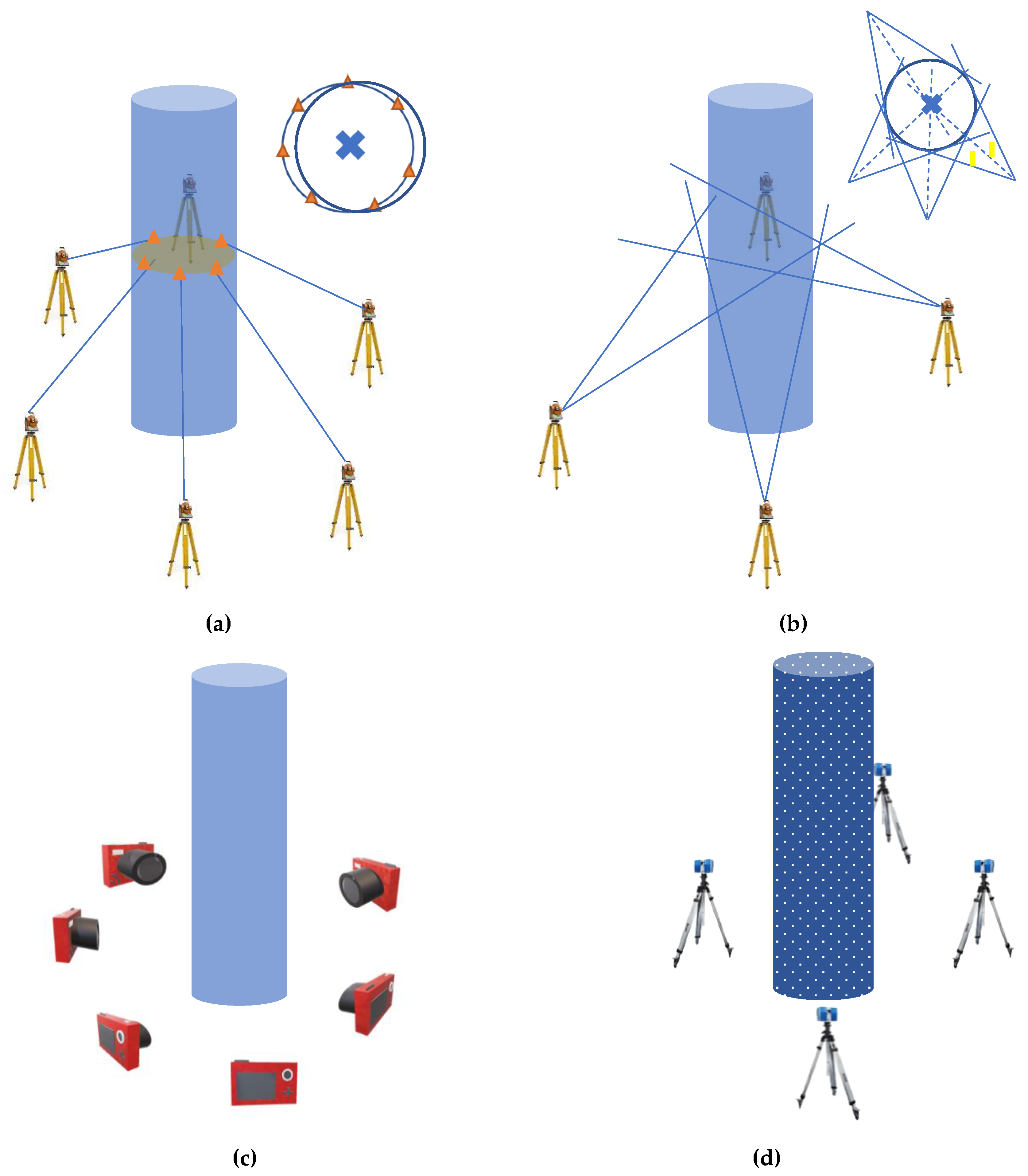
Geodetic techniques: these techniques are the most accurate, where several control targets are placed on specific preselected locations of the study object. Total station instruments are used to fix the coordinates of the control points and baselines with millimetric accuracy in a predesigned network [2]. Frequently, GPS is also used for absolute positioning of the control network. This technique is based on measuring sparse target control points on the structure surface body (Figure 1a). The cylindrical axis is then defined at multiple heights from the best fit circles of the points. Other old techniques included using theodolite instruments, whereby angles are halved to define the cylindrical axis (Figure 1b) at multiple heights.
In recent years, geodetic techniques for tall structures like towers and skyscrapers have started using a combined sensor-assisted approach [3]. As an example, Leica Geosystems has developed the Core Wall Control Survey System (CWCS), which uses GPS sensors combined with high-precision inclination sensors and total stations to deliver precise and reliable coordinates [4].
-
Laser scanning techniques TLS: these techniques are applied normally from terrestrial-based time of flight (TOF) ranging scanners or phase-based laser scanners (Figure 1d). The TLS approach [5,6,7,8,9,10] has the advantage of high positioning accuracy, while it depends on the intrinsic noise of the instrument and how good the coregistration of the multiple scanning point clouds is. Compared to image-based approaches, the TLS is higher in cost, heavier, and requires a level of proficiency.
-
Photogrammetric techniques: these techniques are applied using image-based methods (Figure 1c). These techniques [11,12] range from centimetric to sub-centimetric accuracy depending on the type of camera, image network preplanning, accessibility around the object, illumination, etc.
In this paper, we use photogrammetric image-based methods to create the minaret point clouds, because they have the following advantages:
  • They have lower cost compared to the geodetic and laser scanning approaches.
  • They are portable and can be applied in situ without disturbing site visitors.
  • The available state-of-the-art software tools for automated image-based 3D modeling [13,14,15].
  • The possibility to reconstruct lost heritage models using archived and crowdsourced images and videos.
Accordingly, this ease of use, highly detailed reconstruction of the objects, and the permitted accuracy mentioned above comprise the advantages of using this photogrammetric technique for the out of plumb assessment of heritage minarets. In Section 2, below, we introduce three possible techniques of the geometric primitive fitting for the out of plumb calculations. Then, two experimental tests will be discussed in Section 3 for the out of plumb assessment of cultural heritage minaret structures.

2. Out of Plumb Computation Method

To calculate the out of plumb inclination of a cylindrical-like minaret body, we suggest a geometric primitive fitting, namely a cylinder, cone or a 3D circle fitting.

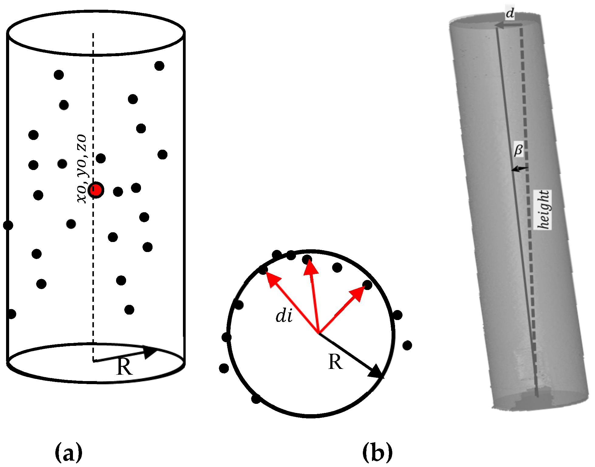
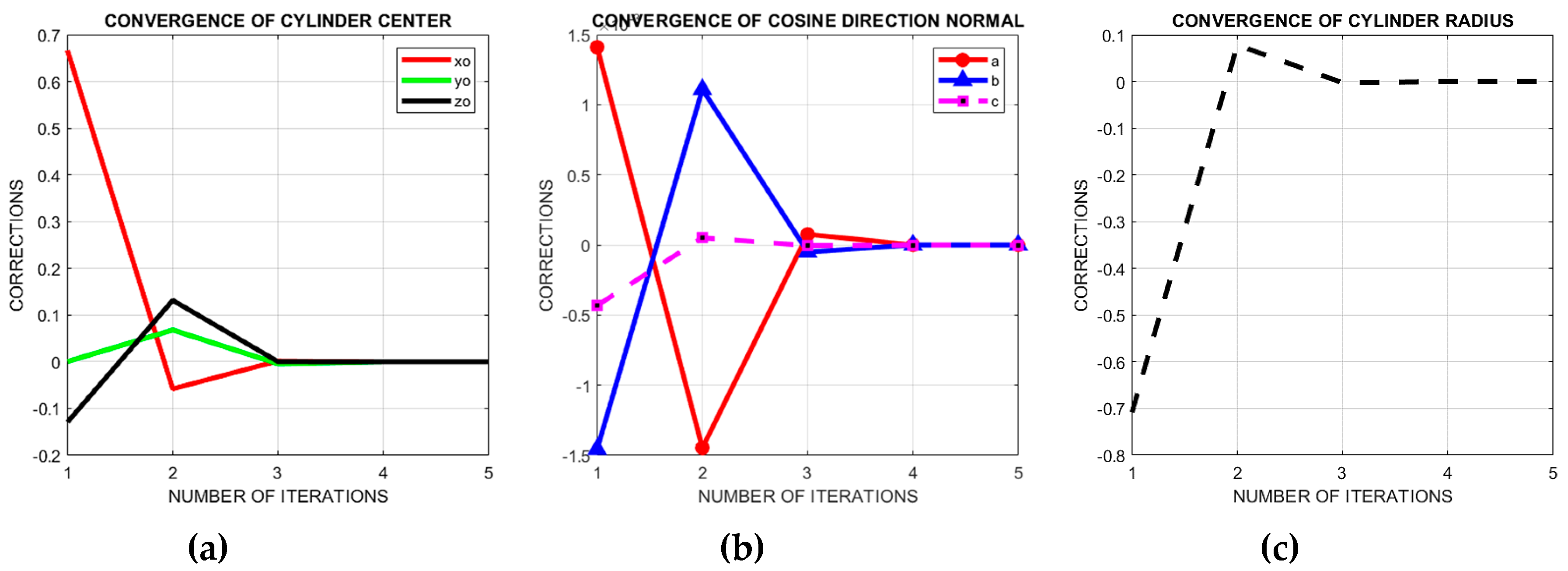
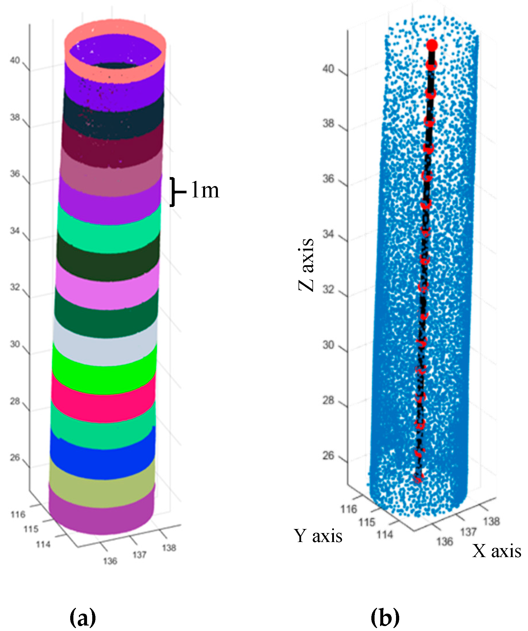
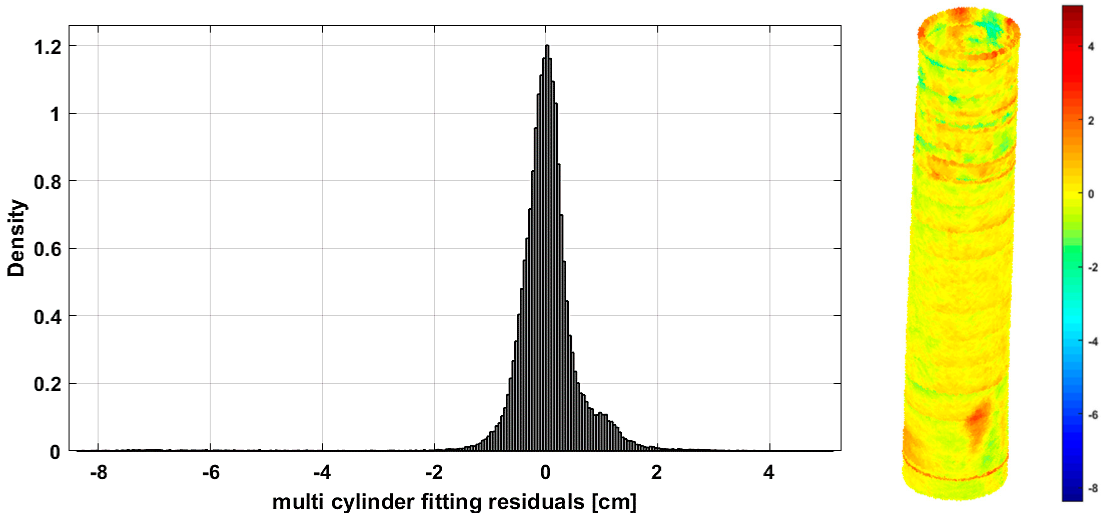
2.1. Cylinder Fitting

There are different methods of least squares fitting of a cylindrical shape [16,17,18]; either linear- or nonlinear-based solutions. Normally, seven parameters are used to define a cylinder (Figure 2):
  • Point of origin lying on the cylinder axis, defined as xo, yo, zo.
  • Cosine direction normal a, b, c of the cylinder axis.
  • Radius of the cylinder R.
In this subsection, we will introduce a modified approach in computing the unknown parameters xo, yo, zo, R and normal cosine direction [ a , b , c ] of the cylinder axis using nonlinear least squares adjustment as follows:
-
The first derivation step is to apply the cross product between the vector derived from the coordinate differences and the cosine direction as:
E = [ a b c ] × [ x xo y yo z zo ] d = E
where × refers to cross product and ∥ ∥ refers to norm.
Therefore, the objective function is to minimize the difference between the distances from the fitting points to the cylinder axis and its radius R as illustrated in Figure 2.
Or
EF = min . ( di R ) 2
The observation equation V = B Δ F can be formed for n points as follows:
[ v 1 v 2 v n ] = V n 1 [ F 1 a F 1 b F 1 c F 1 R F 1 xo F 1 yo F 1 zo F n a F n b F n c F n R F n xo F n yo F n zo ] B n 7 [ Δ a Δ b Δ c Δ R Δ xo Δ yo Δ zo ] Δ 7 1 [ F 1 F 2 F n ] F n 1
where
  • Δ: vector of corrections to fitting parameters.
  • V: vector of residual errors.
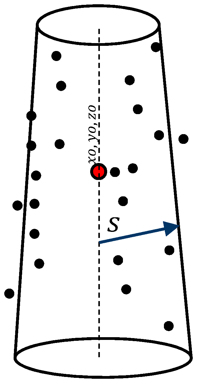
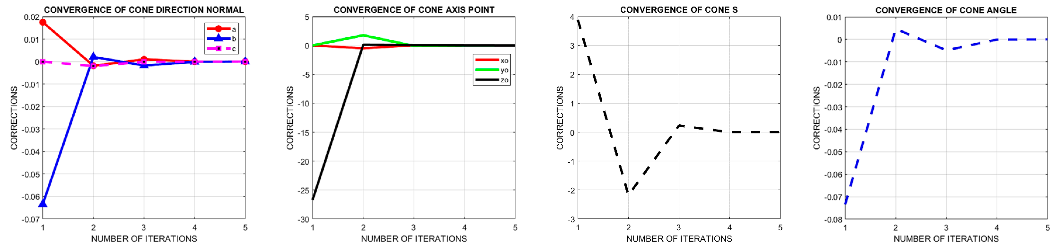
Furthermore, to avoid the rank deficiency in the partial derivatives B matrix, two constraint equations C1 and C2 are added to the system as follows:
1st constraint: the cosine direction vector a, b, and c should be normalized as ( a 2 + b 2 + c 2 = 1 ) , Therefore, the constraint equation matrix C1 will be:
C 1 = [ 2 a   2 b   2 c   0   0   0   0 ] ,   g 1 = [ 1 a 2 b 2 c 2 ]
2nd constraint: the second constraint equation that should be added is based on the dot product between the cosine direction a, b, and c of the cylinder axis and the origin center point 0, or:
a . xo + b . yo + c . zo = 0
Therefore:
C 2 = [ xo yo zo a b c 0 ] ,   g 2 = [ a . xo + b . yo + c . zo ]
Accordingly, Helemert’s method is used to solve the constrained problem as follows [19]:
[ N C t C 0 ] [ Δ k c ] = [ t g ]   where   C = [ C 1 C 2 ] ,   g = [ g 1 g 2 ] ,   N = B t B ,   and   t = B t F
Because of the large number of fitting points, it is expected to have some amount of noisy points, and as a result, a possibly error-prone estimation of the parameters. Therefore, the detection of blundered points using a voting method is applied in the form of the well-known “RANdom SAmple Consensus” (RANSAC) [20,21]. In the RANSAC algorithm, we assume the observational data to include both: inliers and outliers. Inliers can be described as observations without blunders with respect to a specific model, while outliers do not fit that model in any condition. It should be noted that the RANSAC algorithm can find adjustment models even if 50% of the input data set is affected by noise points. On the other hand, there is no guarantee of reaching the optimal solution if we limit the number of iterations.

2.2. Cone Fitting

A similar approach of least squares fitting can be applied to the cone shape [16]. Normally, eight parameters are used to define a cone (Figure 3):
-
Point of origin lying on the cone axis and defined as xo, yo, zo.
-
Cosine direction numbers a, b, c of the cone axis (pointing to the apex).
-
Orthogonal distance from the point of origin to cone s.
-
The cone’s apex semi-angle θ.
The least squares adjustment technique will be applied to minimize the computed distance d between the cone axis and the fitting points as:
d = f i cos θ + g i sin θ s
where
f i = u 2 + v 2 + w 2
u = c ( y i y ) b ( z i z ) v = a ( z i z ) c ( x i x ) w = b ( x i x ) a ( y i y )
g i = a ( x i x ) + b ( y i y ) + c ( z i z )
Therefore, the objective function is to minimize the distances from the fitting points to the cone surface, as illustrated in Figure 3.
Or
F = min . ( di ) 2
The observation equation V = B Δ F can be formed for n points as follows:
[ v 1 v 2 v n ] = V n 1 [ F 1 a F 1 b F 1 c F 1 s F 1 xo F 1 yo F 1 zo F 1 θ F n a F n b F n c F n s F n xo F n yo F n zo F n θ ] B n 8 [ Δ a Δ b Δ c Δ s Δ xo Δ yo Δ zo Δ θ ] Δ 8 1 [ F 1 F 2 F n ] F n 1
Similar geometric constraints mentioned in the cylinder fitting problem are used to run a full rank least squares adjustment (Equation (7)) of the best cone fitting.
After the calculation of the fitting parameters either for the cylinder primitive or the cone, the angular orientation of the cylinder axis is computed as follows:
α = cos 1 ( a / a 2 + b 2 + c 2 β = cos 1 ( b / a 2 + b 2 + c 2 γ = cos 1 ( c / a 2 + b 2 + c 2
However, for such vertical primitive objects, we only need the γ inclination angle to compute the out of plumb as follows (Figure 2b):
Out   of   plumb   =   γ × height
Whereas α and β are used to determine the out of plumb direction if needed. The standard deviation of the out of plumb in Equation (15) can be computed using the propagation of errors technique. However, tests showed that the computed standard deviations of the cosine directions are of small magnitude, and the out of plumb accuracy is mainly related to the estimated height accuracy. Accordingly, the estimated accuracy of the out of plumb in the following experimental tests are assumed equivalent to the accuracy of the primitives fitting of the point clouds.

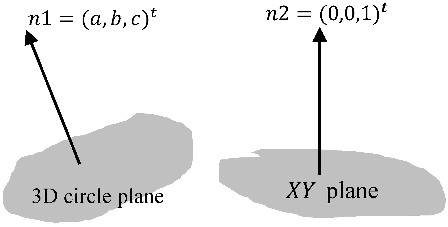
2.3. Circle Fitting in 3D space

Fitting a circle in 3D space (Figure 4) needs a multistep solution approach, as follows [16,22]:
  • Compute the best fit least squares plane of the data as explained previously.
  • Rotate the points such that the least squares plane is the XY plane.
  • Rotate data points onto the XY plane.
  • Compute the 2D circle fit in the XY plane.
  • Rotate back to the original orientation in 3D space.

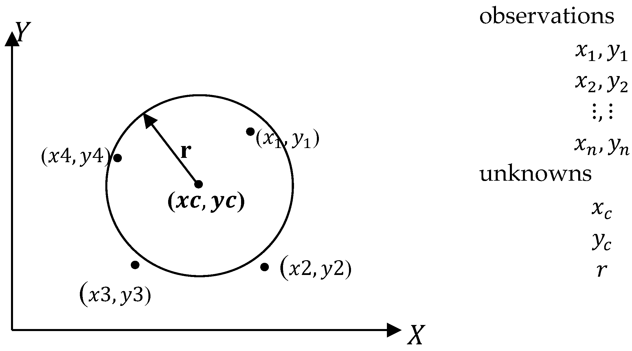
2.3.1. Fitting a 2D Circle

The least squares adjustment of a circle best fit in a 2D space is shown in Figure 5 as follows:
  • Given: XY points, i = 1:n
  • Required: the adjusted radius r, and circle center x c , y c
Circle equation can be formulated as:
( x x c ) 2 + ( y y c ) 2 r 2 = 0
The observation equation will be as follows in the form V = B Δ F
[ v x 1 v y 1 v x 2 v yn v zn ] = [ F 1 x c F 1 y c F 1 r F n x c F n y c F n r ] [ δ x c δ y c δ r ] [ r 2 ( x 1 x c o ) 2 ( x 1 y c o ) 2 r 2 ( x n x c o ) 2 ( x n y c o ) 2 ]
The partial derivatives of the function to the unknowns will be as follows:
F 1 x c = 2 ( x x c o ) F 1 y c = 2 ( y y c o ) F 1 R = 2 r o
Then a least squares adjustment is performed as Δ = ( B t B ) 1   ( B t F ) .

2.3.2. Rodrigues Rotation Formula

To apply the 2nd step of rotating the points to the best fit plane of points, we can utilize the Rodrigues rotation formula to rotate 3D points and get their XY coordinates in the coordinate system of the plane. This is simply a problem of rotating from normal vector n 1 to normal n 2 , as shown in Figure 6.
To compute the rotation matrix, we will apply the following steps:
  • Find the axis and angle of rotation using cross product and dot product respectively. The axis of rotation k is a cross product (×) between plane normal n 1 and the normal of the new XY coordinates. Thus, n 2 = ( 0 , 0 , 1 ) t and k = n 1 × n 2 . Furthermore, θ   =   cos 1 ( n 1 . n 2 n 1 . n 2 )
  • Find the rotation matrix M using exponential map:
    M = I 3 3 + k ^ sin ( θ ) + k ^ 2 ( 1 cos θ )
    where
    -
    Skew—symmetric matrix k ^ =   [ 0 k ( 3 ) k ( 2 ) k ( 3 ) 0 k ( 1 ) k ( 2 ) k ( 1 ) 0 ]
    -
    k = ( n 1 × n 2 ) , then normalized.
The 3rd step after rotation of points is to find the best fit circle Cpoints in 2D space ( xc , yc , r ). Finally, rotate back to 3D space by taking n2 as the plane normal and n 1 = ( 0 , 0 , 1 ) t
C = Cpoints [ xc , yc , 0 ]
C   =   C M   +   Points _ mean

3. Results and discussion

Two experiments were conducted at Iraqi cultural heritage sites using the suggested geometric primitive fitting. The first experiment was carried out on the inclined minaret of the Imam AlKadhim shrine in Baghdad, and the second experiment was carried out on the lost al Hadbaa minaret in Mosul.

3.1. First Experiment

The Imam Musa AlKadhim shrine was first constructed in 1058 AD (450 Hijri), and included a mosque and one minaret; in 1098 AD, two further minaret structures were added. Then, during the rule of caliph Al Mustansir Billah in 1226 AD, the whole shrine structure was completed [23,24]. In 1508 AD, Shah Ismail Safavi added two more minarets to become four, as is still the case in our current time, and as shown in Figure 7 with two domes beside the four minaret structures.
Each minaret has a foundation 11 m in the ground and an elevation 28 m above the ground, which means a total of 39 m from the base to top. In 2013, an out of plumb increase was observed in the minaret structures, in addition to some cracks in the walls, both inside and outside. This indicated a problem with the site foundations and the soil due to the groundwater and the renovations previously applied at the shrine site.
Therefore, there was a need to ensure the visitors’ safety and to find suitable construction engineering solutions to resolve the problems with the foundations and the groundwater. Furthermore, monitoring the minarets’ stability, calculating the out of plumb, and fixing the wall cracks in the shrine structures was necessary. This was achieved by an extensive project which included TLS scanning of the whole shrine site in addition to geodetic monitoring of the minaret inclinations [24].
Conventionally, geodetic monitoring techniques are applied through multiple epoch measurements of the questionable minarets of the heritage site. Total station measurements are applied to selected critical points on the cylindrical body of each minaret, which comprise circular planes at multiple selected elevations. Then for each circular plane/section, the center coordinates are determined by applying the least squares adjustment for fitting a 2D circle.
The monitoring of the shrine site was carried out from May 2014 to August 2015 using the described geodetic methods, and with photogrammetric techniques, as well. The applied photogrammetric techniques were based on manually measuring the interest points of the minaret using an SLR camera at individual strips around the four minarets [24].
For both measuring techniques, 2500 monitoring object points were measured in the designed multi planes to compute their center points, defining the vertical axis of the minaret structures. It was observed that two minaret structures were stable, while the inclination was critical for the two other minarets [24].
In this paper, the inclination of one of the suspected renovated minaret structures was determined after three years of treatment to check its stability and whether there is still a critical out of plumb in its structure.

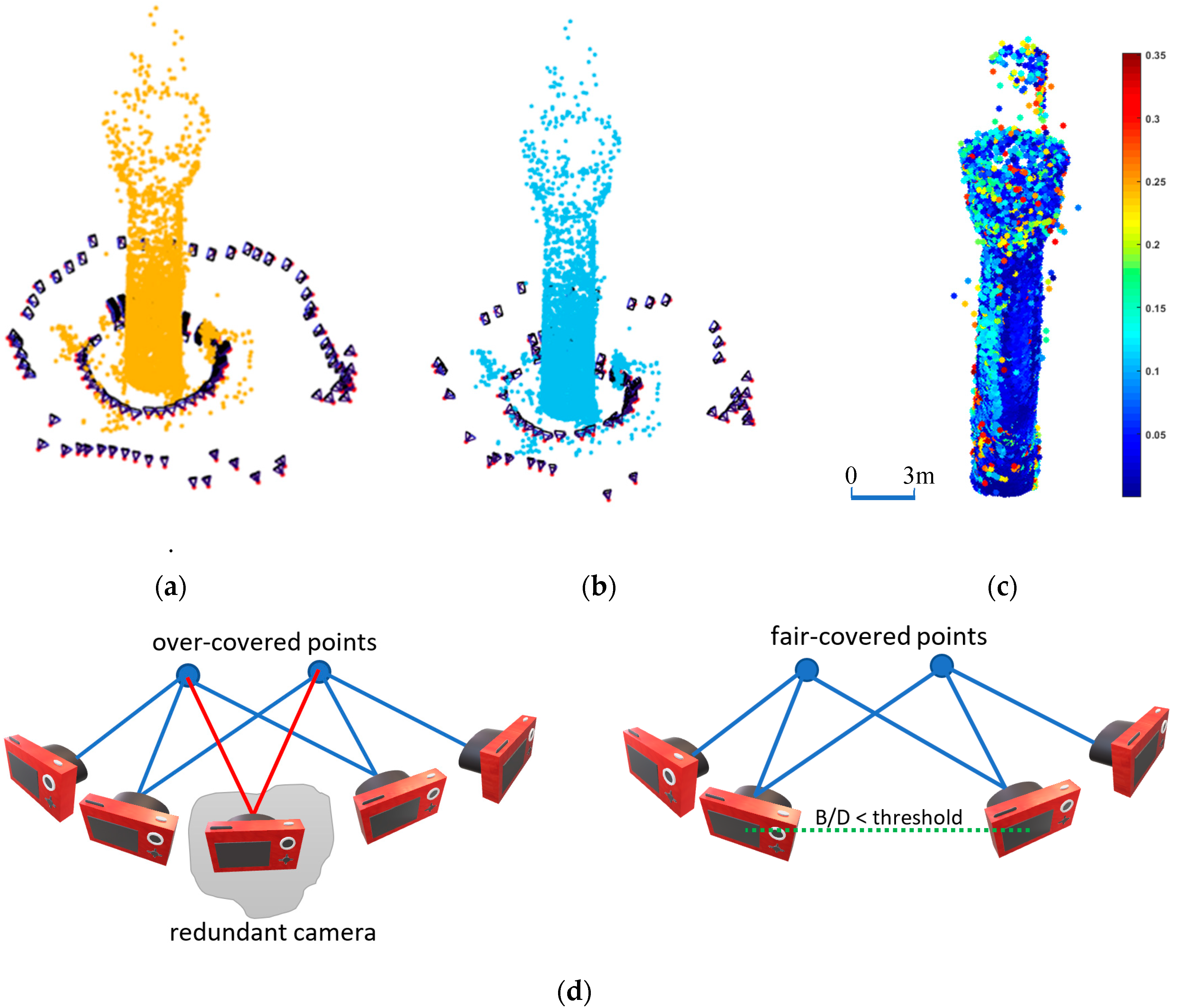
3.1.1. Close-Range Photogrammetry

First, a pre-analysis of the camera network around the minaret structure was carried out by reconnaissance and checking accessibility spaces. Unfortunately, it was only possible to capture the image from the ground, and no drone photogrammetry was permitted at the shrine site during the daytime. Therefore, it was decided to capture the images in a highly overlapped strip of images. Images were captured using a DSLR Canon EOS Mark III camera with a fixed focal length of 24 mm and an image frame size of 5760 × 3840 pixels. An average capture distance of 6 m was designated in order to guarantee a depth accuracy of 5 mm with an average ground sample distance (GSD) of 2 mm, as shown in Equation (22) [25].
Z = 3 fB σ Z p
where
  • σz = precision at object space [mm]
  • f = focal length [mm]
  • B = base line (step size) [mm]
  • p = pixel pitch (width) [mm]
However, higher parts of the minaret were expected to have larger depth accuracy and GSD.
Practically, a total of 450 images were captured in two rings around the minaret structure in different portrait and landscape orientations. To avoid the long processing time required to create the dense point cloud in our laptop machine, and to perform an efficient imaging network configuration for future image capture, we applied the minimal camera network approach presented in [26].
The minimal camera network filtering technique is based on the concept of having at least three images (cameras) viewing the object point simultaneously. The approach starts by labeling the derived sparse point cloud of the object as either over-covered or fair-covered. Over-covered points are the points that appear in more than three images, while fair-covered points, refer to the points that typically appear in three cameras. Therefore, the images are considered redundant and are filtered out if they exclusively contribute points that are covered by more than three cameras, as shown in Figure 8d. The camera filtering is allowed if it maintains the desired small Base/Distance ratio. The filtering is repeated until no more redundant cameras are involved in imaging over-covered points. Accordingly, the number of images around the shrine minarets is reduced from 450 to 169 images (Figure 8a,b) and oriented using the Metashape software tool [13].
The quality of the reconstructed minaret object is evaluated by computing the variance-covariance matrix of the tie points using a separate code. The quality computations are applied through the bundle adjustment of the images and the calculation of the mean of the error ellipsoid axes for each tie point. Then every point is colored with respect to the computed mean error, as shown in Figure 8c. Table 1 summarizes the camera specifications and the imaging network orientation quality.
Mathematically, a minimum of three control points is sufficient to geo-reference the imaging network and, subsequently, the derived point cloud. However, adding more control points is necessary to reliably check the quality of the orientation and the produced point cloud. In this experiment, it was difficult to fix more than four control points because of the limitations regulated by the shrine authorities during the field work.
The root mean squared error (RMSE) of the four control points we used is computed as: σx = 1.2 mm, σy = 2.4 mm and σz = 1.6 mm, respectively.
Afterward, the highly dense 3D point cloud of ≈3 million points was reconstructed, as shown in Figure 9a. A density analysis showed that the average number of points was 15,300 ± 4150 points/m2, which is a high level of density that will certainly give a reliable 3D representation of the minaret (Figure 9b).

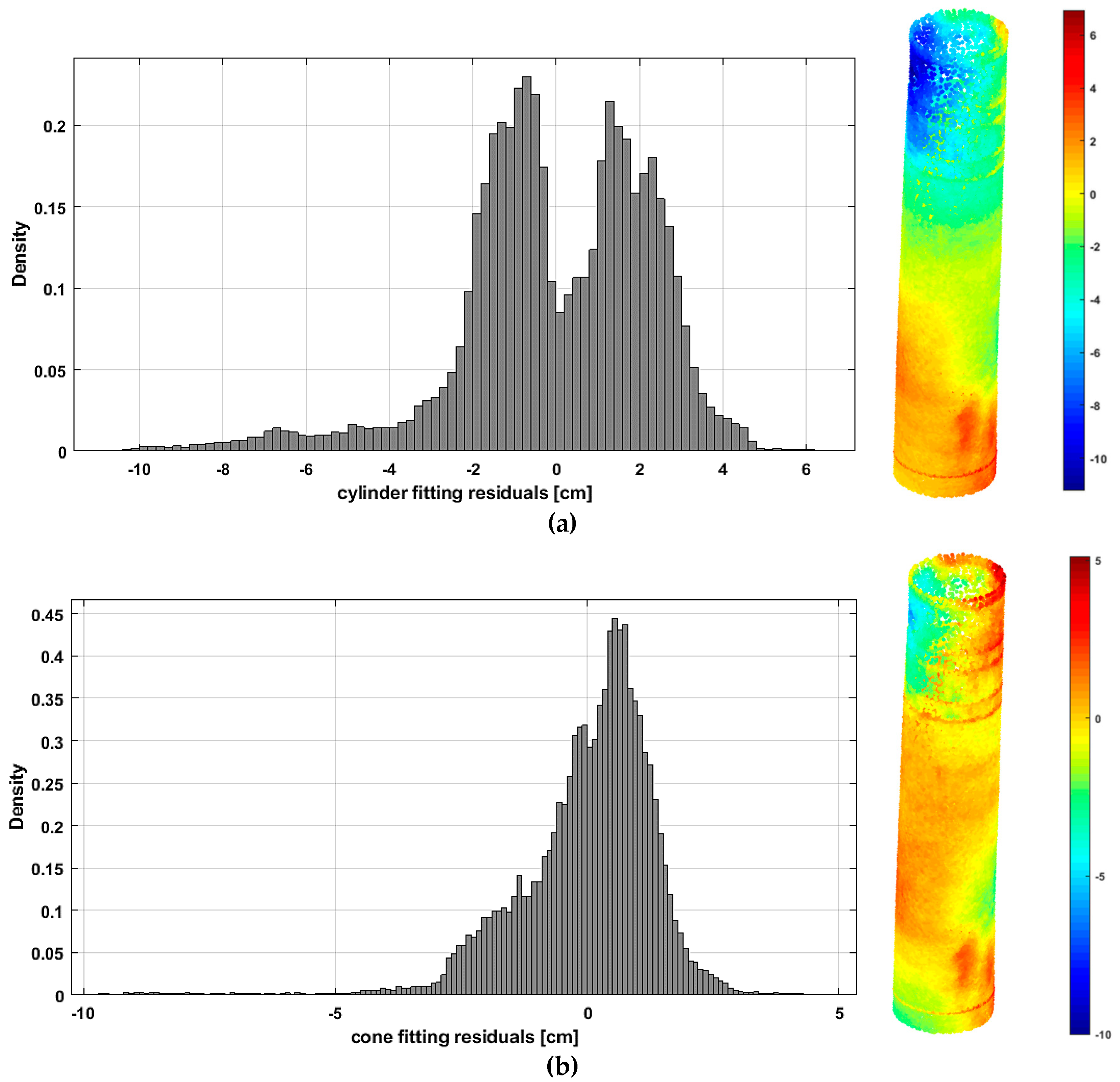
3.1.2. Geometric Primitive Fitting of the Shrine Minaret

As mentioned, a geometric cylinder and cone fitting is applied to the minaret point cloud to estimate the out of plumb of the minaret axis. Figure 9c shows the best fitting cylinder, and in Figure 9d, the best fitting cylinder is fused with the minaret point cloud. Using the formulas in Section 2.1, the least squares solution is converged to optimal values (Figure 10).
Geometrically, it is clear that the minaret body is not a perfect cylinder, because whenever the points are higher, the diameter is slightly decreased. Therefore, a more efficient fitting is applied either by assuming a cone minaret body for the whole point cloud or by fitting multiple cylinders in elevated adjacent sections.
Originally, the out of plumb computations using Equation (15) are applied using a cylinder and a cone fitting for the whole point cloud, and the results are listed as follows in Table 2, where the computed out of plumb is shown:
To evaluate the goodness of the primitive fitting, we compute the distance between every point and both the cylinder and the cone surfaces, respectively. The results are shown where the mean distance is ±2.3 cm from the fitting cylinder surface (Figure 11a), while it is ±1.4 cm from the fitting cone surface (Figure 11b).
The third fitting option is to use a cylinder or a cone fitting at multiple elevations. Accordingly, multiple height sections with a width of 1 m are selected from the point cloud and followed by a cylindrical or conical fitting applied for each level.
Table 3 illustrates the seven parameters of the fitting cylinders in the multi elevation sections shown in Figure 12a. The last column in Table 2 shows the computed out of plumb inclination between every section and the minaret base using the planimetric coordinates of the involved cylinder centers as in Equation (23):
out   of   plumb =   ( X top X bottom ) 2 + ( Y top Y bottom ) 2
It is shown that the computed horizontal shift between the minaret base and its top is 45 cm, which represents the out of plumb inclination of the minaret. The result is similar to the field survey measurements implemented by professional surveyors.
As previously stated, Table 3 shows that the radius of the cylindrical minaret tower decreases from bottom to top, and fitting the whole minaret body with one cylinder or cone would not be so accurate. Similar to Figure 11, the multi cylinder fitting is evaluated by computing the distances between the point cloud and the fitting cylinders. Then the standard deviation of 1σ is computed as ±0.8 cm, indicating the high precision of the multi cylinder fitting to the point cloud, as shown in Figure 13.
A thorough verification of the computed out of plumb of Table 3 shows that the inclination is not truly linear, but somehow curvilinear. The best fitting polynomial is found to be cubic with a norm of residuals of 2 cm as shown in Figure 14:
y   =   p 1 x 3 + p 2 x 2 + p 3 x + p 4
where
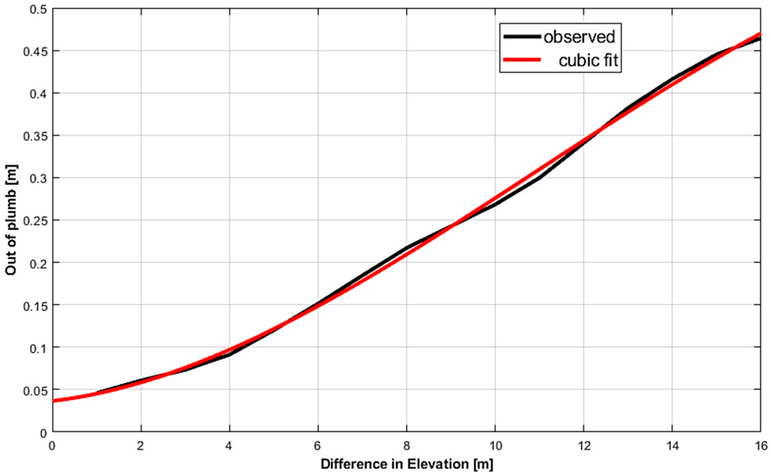
  • y: the out of plumb in [m].
  • x: difference of elevations [m].
  • p1 = −7.84 × 10⁻⁵, p2 = 0.003, p3 = 0.006, and p4 = 0.037
Obviously, the minaret was built from bricks line by line, using the techniques available at the time of construction, which are not accurate according to our current standards; this resulted in the slightly curvilinear plumb axis of the minaret.
Finally, a 3D circle fitting is applied to the selected multiple sections of the minaret point cloud and the computed out of plumb is 45 cm with a fitting residuals standard deviation of ±6 cm. The results of the four fitting scenarios show that the best approach is to apply multiple cylindrical sections fitting.

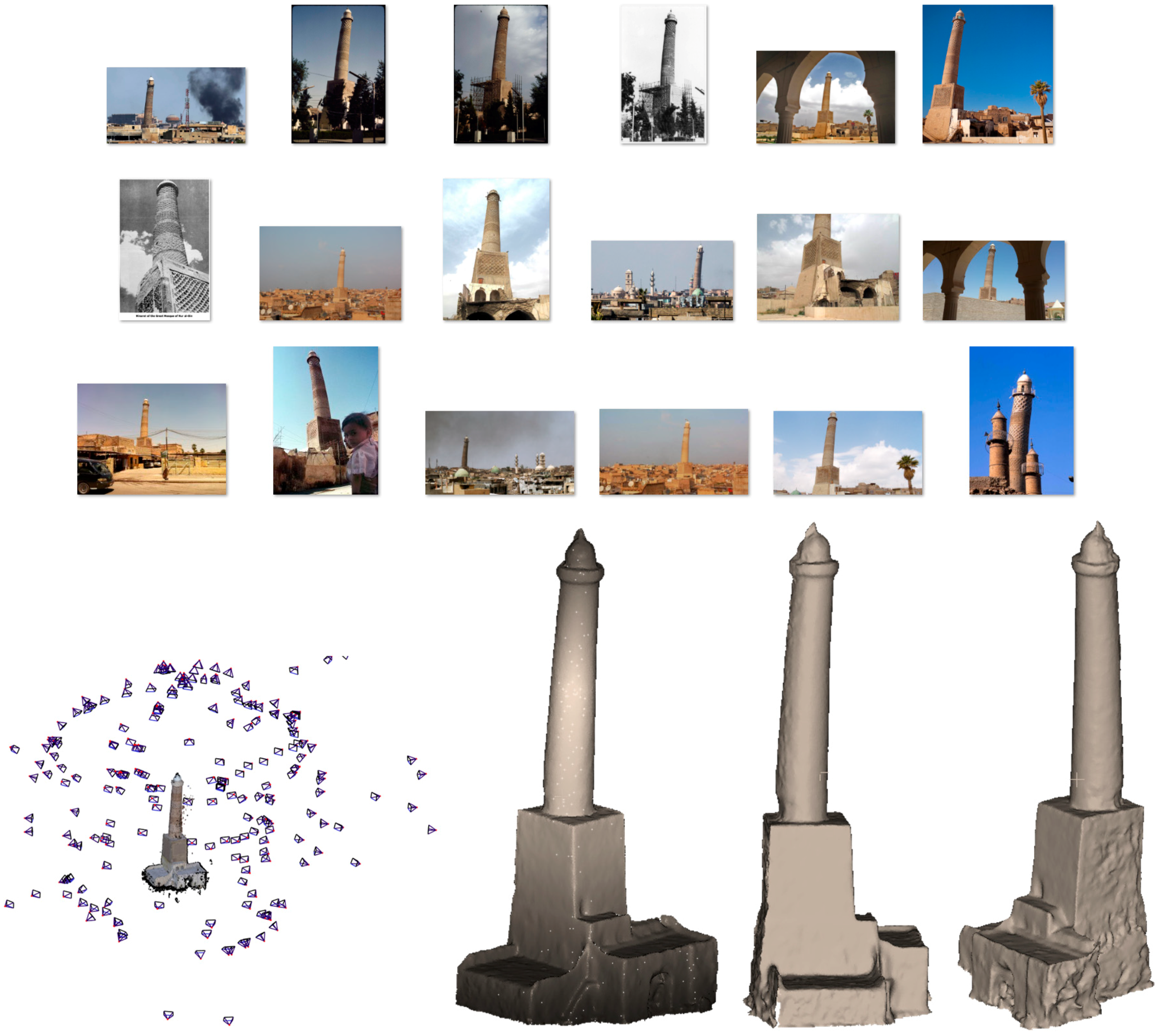
3.2. Second Experiment

The Al-Hadbaa leaning Minaret (Figure 15a) is one of the remarkable monuments in Iraq which was destroyed in 2017 (Figure 15b) during the liberation of the old city of al-Mosul from ISIS [1,27]. The minaret was established in the year 1173 AD (568 Hijri) during the Seljuk rule of Nur ad-Din Zenki.
The minaret is a part of the construction of the Great Mosque or al-Nuri mosque and is known as Al-Hadbaa which means “the hunchback” in the Arabic language. Since 2003, the image of the minaret has decorated one of the banknotes in the Iraqi currency.
According to [28], the cylindrical body of the minaret, which has an elevation of 47.25 m, starts at a level of 17.31 m with a diameter of 2.62 m. The minaret consisted of three parts: the foundations; a prismoid base with dimensions of 12 m, 2 m below the ground; and the cylindrical-like minaret. The minaret is built out of brick with plaster materials, while the internal stairs inside the minaret are built of stone. The effect of the weather and the weak construction materials caused the leaning of the minaret body over the course of hundreds of years after it was established, with a lean of 2.19 m at a height of 47.25 m, as measured in 1981 [28].
Similar to the lost minaret of Aleppo in Syria [29], and based on the archived multimedia records of the minaret, engineering descriptions in the literature, and published 3D models in SketchUp 3D warehouse [30] and Sketchfab [31], a 3D image-based model was created (Figure 16). The model was scaled to reality based on the published dimensions of the minaret base of 9 × 9 meters [28]. Subsequently, a 3D point cloud was created, and the out of plumb computations were performed similarly to the procedure in the first experiment. It should be noted that the point cloud (≈700,000 points) was of moderate accuracy, since it was mainly based on low-resolution crowdsourced images available to the public. Furthermore, since this minaret object is lost, no field measurements could be applied, and the comparisons are based on the out of plumb reported previously.
From the geometric description of the minaret and the available images, it is obvious that the minaret body was not a completely regular cylinder or cone, since at higher points, the diameter is slightly decreased and leans with a curvilinear axis.
Therefore, we apply two kinds of fitting, similar to in the previous experiment: first, by assuming a conical body for the whole minaret; and second, by assuming multiple cone sections with width of 1 m for fitting.
The out of plumb computations of 1.9 m, as shown in Table 4, result from using Equation (15) for the whole point cloud cone fitting; the least squares results are shown in Figure 17:
To evaluate the goodness of the primitive fitting, we compute the distance between every point and the cone surface. The results are shown in Figure 18a, where the median of the residuals between the cone surface and the points is −27 cm and the standard deviation is ±9.7 cm of 1σ.
Meanwhile, the out of plumb is computed as 2.3 m using the multi conical section fitting (Figure 18b), with a higher precision for a zero median and ±5 cm standard deviation of 1σ. This computed out of plumb is in agreement with the measured deviation reported in [28] using field surveying methods in 2007.
Lastly, a 3D circle fitting is applied to multiple selected sections of the minaret point cloud, and the computed out of plumb is 2.27 m with a standard deviation of the fitting residuals of ±4.8 cm.

4. Conclusions

In this paper, we presented a geometric primitive fitting approach for calculating the out of plumb of cylindrical-like cultural heritage minaret towers. Three types of primitive fittings for the minaret point clouds are suggested, namely: cylinder, cone and 3D circle.
In the first experiment, the approach is applied with respect to the minaret at the holy shrine of Imam AlKadhem by following the photogrammetric engineering techniques of different tasks. The tasks included:
  • Preplanning, image capture with a professional camera.
  • Automated image orientation using state-of-the-art software tool.
  • Using field survey control points for reality scaling.
  • Creating a dense point cloud for 3D modeling of the minaret.
  • and finally, to compute the out of plumb amount by primitive fitting of the point clouds.
Error analysis showed (Figure 8c) that the oriented images were able to meet centimetric accuracy of the modeled points of the minaret. Furthermore, the RMSE of the control points was less than half a centimeter. In addition to cleaning the noise from the point cloud, which was of minor magnitude, the RANSAC technique was also applied during the fitting calculations to avoid the effect of the noisy points if they were present on the reliable fitting parameters.
The geometric primitive fitting calculations showed the existence of an out of plumb inclination of 45 cm between the top and the bottom of the shrine minaret body, as illustrated in Table 1 and Table 2. Statistical analysis showed that multi cylinder fitting to the point cloud of the minaret body was accurate to within 1 cm at 68% probability (1σ), as shown in Figure 13. Furthermore, because the minaret was built from bricks line by line, it was found that the out of plumb inclination of the minaret body is better fitted to a cubic polynomial rather than a straight line (Figure 14). These results have been reported to the shrine administration authorities in order to handle the proper structural treatment and monitoring of the minaret.
The second experiment was applied with respect to a digital model of the lost heritage site of the al Hadbaa minaret (Figure 15). A cone fitting is applied, rather than a cylinder fitting, because of the conical-like shape of the minaret. The computed out of plumb using one cone fitting for the whole point cloud was 1.9 m, with an accuracy of 10 cm (Figure 18a), whereas the computed multiple sections of cone fitting and the 3D circle fitting both resulted in 2.3 m out of plumb (Figure 18b). Using the cone primitive has a higher precision of ±5 cm, which is closer to the reported inclination results in 2007.
Accordingly, the proposed primitive fitting showed reliable estimation of the out of plumb of the cylindrical-like minarets, which can be automated and integrated with state-of-the-art software tools.
For future work, we will consider the out of plumb computation of other geometrically shaped objects, like squared minarets, using the proposed technique of primitive fitting. Similarly to our second experimental test of the al Hadbaa minaret, the lost heritage of the great mosque minaret of Aleppo in Syria is a recognizable future case study of square-like minarets.

Author Contributions

Field work, Y.H.K. and N.A.A.; Resources, N.A.A., Y.H.K. and B.A.; Software, B.A.; Supervision, B.A.; Visualization, B.A.; Writing, B.A.

Conflicts of Interest

The authors declare no conflict of interest.

References

  1. United Nations Education, Scientific and Cultural Organization UNESCO. 2018. Available online: https://en.unesco.org/news/uae-unesco-and-iraq-conclude-historic-50m-partnership-reconstruct-mosul-s-iconic-al-nouri (accessed on 17 November 2018).
  2. Beshr, A.A. Structural Data Analysis for Monitoring the Deformation of Oil Storage Tanks Using Geodetic Techniques. J. Surv. Eng. 2014, 140, 1. [Google Scholar] [CrossRef]
  3. Ayman, H.; Ashraf, O.; Charles, M. Monitoring the structural response of historical Islamic minarets to environmental conditions. In Proceedings of the SMAR—Fourth Conference on Smart Monitoring, Assessment and Rehabilitation of Civil Structures, Zurich, Switzerland, 13–15 September 2017. [Google Scholar]
  4. Controlling Vertical Towers. Available online: https://w3.leica-geosystems.com/media/new/product_solution/Leica_Geosystems_TruStory_Controlling_Vertical_Towers.pdf (accessed on 15 October 2018).
  5. Jaafar, H.A. Detection and Localisation of Structural Deformations Using Terrestrial Laser Scanning and Generalised Procrustes Analysis. Ph.D. Thesis, University of Nottingham, Nottingham, UK, 2017. [Google Scholar]
  6. Jatmiko, J.; Psimoulis, P. Deformation Monitoring of a Steel Structure Using 3D Terrestrial Laser Scanner (TLS). In Proceedings of the 24th International Workshop on Intelligent Computing in Engineering, Nottingham, UK, 10–12 July 2017; Available online: https://www.researchgate.net/publication/318658994_Deformation_Monitoring_of_a_Steel_Structure_Using_3D_Terrestrial_Laser_Scanner_TLS (accessed on 15 October 2018).
  7. Selbesoglu, M.O.; Bakirman, T.; Gokbayrak, O. Deformation Measurement Using Terrestrial Laser Scanner for Cultural Heritage. In Proceedings of the International Archives of the Photogrammetry, Remote Sensing and Spatial Information Sciences, Istanbul, Turkey, 16–17 October 2016; Volume XLII-2/W1, pp. 89–93. [Google Scholar]
  8. Gordon, S.J.; Lichti, D.D. Modeling terrestrial laser scanner data for precise structural deformation measurement. J. Surv. Eng. 2007, 133, 72–80. [Google Scholar] [CrossRef]
  9. Park, H.; Lee, H.; Adeli, H.; Lee, I. A new approach for health monitoring of structures: Terrestrial laser scanning. Comput. Aided Civ. Infrastruct. Eng. 2007, 22, 19–30. [Google Scholar] [CrossRef]
  10. Giuseppina, V.; Fausto, M.; Flavio, S. Terrestrial Laser Scanner for Monitoring the Deformations and the Damages of Buildings. In Proceedings of the XXIII ISPRS Congress, Prague, Czech Republic, 12–19 July 2016; Volume XLI-B5, pp. 453–460. [Google Scholar] [CrossRef]
  11. Hanke, K.; Grussenmeyer, P. Architectural Photogrammetry: Basic theory, Procedures, Tools. September 2002 ISPRS Commission 5 Tutorial. Available online: http://www.isprs.org/commission5/tutorial02/gruss/tut_gruss.pdf (accessed on 25 July 2018).
  12. Nocerino, E.; Menna, F.; Remondino, F. Accuracy of typical photogrammetric networks in cultural heritage 3D modeling projects. In The International Archives of the Photogrammetry, Remote Sensing and Spatial Information Sciences, Proceedings of the ISPRS Technical Commission V Symposium, Riva del Garda, Italy, 23–25 June 2014; ISPRS: Vienna, Austria, 2014; Volume XL-5, pp. 465–472. [Google Scholar] [CrossRef]
  13. Agisoft LLC. Metashape. Available online: http://www.agisoft.com/ (accessed on 1 October 2018).
  14. Photomodeler. Photomodeler Tecnologies. Available online: https://www.photomodeler.com/ (accessed on 11 October 2018).
  15. Pix4D. Available online: https://www.pix4d.com/ (accessed on 11 October 2018).
  16. Forbes, B.A. Least-Squares Best-Fit Geometric Elements; Report Number: NPL Report DITC 140/89; National Physical Laboratory: London, UK, 1989. [CrossRef]
  17. Craig, M.S. Least-Squares Fitting Algorithms of the NIST Algorithm Testing System. J. Res. Natl. Inst. Stand. Technol. 1998, 103, 634–641. [Google Scholar]
  18. Panyam, M.; Kurfessa, T.; Tucker, T. Least Squares Fitting of Analytic Primitives on a GPU. J. Manuf. Syst. 2008, 27, 130–135. [Google Scholar] [CrossRef]
  19. Ghilani, C.D.; Wolf, P.R. Adjustment Computations Spatial Data Analysis, 4th ed.; John Wiley & Sons, Inc.: Hoboken, NJ, USA, 2006; p. 398. [Google Scholar]
  20. Point Cloud Library PCL Documentation, How to Use Random Sample Consensus Model. Available online: http://pointclouds.org/documentation/tutorials/random_sample_consensus.php (accessed on 5 March 2018).
  21. Fischler, M.A.; Bolles, R.C. Random sample consensus: A paradigm for model fitting with applications to image analysis and automated cartography. Commun. ACM 1981, 24, 381–395. [Google Scholar] [CrossRef]
  22. Miki. Fitting a Circle to Cluster of 3D Points. 2016. Available online: https://meshlogic.github.io/posts/jupyter/curve-fitting/fitting-a-circle-to-cluster-of-3d-points/ (accessed on 21 March 2017).
  23. Musa_al-Kadhim Shrine. Available online: https://en.wikipedia.org/wiki/Musa_al-Kadhim (accessed on 15 February 2018).
  24. Abed, F.; Ibrahim, O.; Jasim, L.; Khalaf, Y.; Hameed, H.; Hussain, Z. Terrestrial Laser Scanning to Preserve Cultural Heritage in Iraq Using Monitoring Techniques. In Proceedings of the 2nd International Conference of Buildings, Construction and Environmental Engineering (BCEE2-2015), Baghdad, Iraq, 17–18 October 2015. [Google Scholar]
  25. Wenzel, K.; Rothermel, M.; Fritsch, D.; Haala, N. Image Acquisition and Model Selection for Multi-View Stereo. In International Archives of the Photogrammetry, Remote Sensing and Spatial Information Sciences, Proceedings of the 3D-ARCH 2013—3D Virtual Reconstruction and Visualization of Complex Architectures, Trento, Italy, 25–26 February 2013; ISPRS: Vienna, Austria, 2013; Volume XL-5/W1, pp. 251–258. [Google Scholar] [CrossRef]
  26. Alsadik, B.; Gerke, M.; Vosselman, G.; Daham, A.; Jasim, L. Minimal Camera Networks for 3D Image Based Modeling of Cultural Heritage Objects. Sensors 2014, 14, 5785–5804. [Google Scholar] [CrossRef] [PubMed] [Green Version]
  27. Al-Hadba’ Minaret—World Monument Fund. Available online: https://www.wmf.org/project/al-hadba%E2%80%99-minaret (accessed on 06 November 2018).
  28. Al-Gburi, M.; Salih, M.; Taeb, S. Study of Maintenance Al Hadba Minaret Monument in Mosul. 2010. Available online: https://www.researchgate.net/publication/268508608_Study_of_Maintenance_Al_Hadba_Minaret_Monument_in_Mosul (accessed on 15 October 2018).
  29. Grussenmeyer, P.; Al Khalil, O. From Metric Image Archives to Point Cloud Reconstruction: Case Study of The Great Mosque of Aleppo in Syria. In International Archives of the Photogrammetry, Remote Sensing and Spatial Information Sciences, Proceedings of the 26th International CIPA Symposium, Ottawa, ON, Canada, 28 August–1 September 2017; ISPRS: Vienna, Austria, 2017; Volume XLII-2/W5. [Google Scholar] [CrossRef]
  30. 3D Warehouse. Available online: https://3dwarehouse.sketchup.com/?hl=en (accessed on 15 October 2018).
  31. Sketchfab. Available online: https://sketchfab.com/models/adefb309080844c6b78370e7c129d4c4 (accessed on 15 October 2018).
Figure 1. Different out of plumb monitoring techniques. (a) Geodetic approach using target point measurements. (b) Geodetic approach using angular measurements. (c) Close range photogrammetric approach. (d) TLS approach.
Ijgi 08 00064 g001
Figure 2. Fitting points to a cylinder primitive and the out of plumb illustration. (a) Fitting of a cylinder defined by seven parameters. (b) Out of plumb illustration.
Ijgi 08 00064 g002
Figure 3. Fitting points to a cone defined by eight parameters.
Ijgi 08 00064 g003
Figure 4. 3D circle fit.
Ijgi 08 00064 g004
Figure 5. 2D circle fit.
Ijgi 08 00064 g005
Figure 6. Rotating from normal vector n1 to normal n2.
Ijgi 08 00064 g006
Figure 7. Shrine of Imam Musa AlKadhim in Baghdad, Iraq with its four minaret structures.
Ijgi 08 00064 g007
Figure 8. Imaging network around the shrine minaret. (a) Full imaging network with 450 images. (b) Filtered imaging network with 169 images. (c) Positional quality estimation represented in colors in cm. (d) The concept of filtering a redundant camera. (left) before filtering, (right) after filtering.
Ijgi 08 00064 g008
Figure 9. The produced image-based point cloud of the shrine minaret. (a) Minaret body with the oriented images around it. (b) Dense point cloud of the minaret. (c) Best fitting cylinder. (d) Fitting cylinder fused with the point cloud.
Ijgi 08 00064 g009
Figure 10. Nonlinear least squares cylinder fitting parameters converged to optimal.
Ijgi 08 00064 g010
Figure 11. Cylindrical and conical geometric primitive fitting results. (a) The distance between the point cloud and the best fit cylinder surface (σ = ±2.3 cm). (b) The distance between the point cloud and the best fit conic surface (σ = ±1.4 cm).
Ijgi 08 00064 g011
Figure 12. Multi cylinder primitive fitting results of the shrine minaret. (a) The cylindrical minaret body is divided into multiple 1 m sections. (b) The barycentric coordinates at each height level is computed through a cylinder fitting.
Ijgi 08 00064 g012
Figure 13. The distances between the multi fitting cylinders surfaces and the related point clouds.
Ijgi 08 00064 g013
Figure 14. The curvilinear relation between the out of plumb of the minaret body and the successive difference in elevations with respect to the minaret base.
Ijgi 08 00064 g014
Figure 15. Al-Nuri Grand Mosque in the Old City of Mosul, Iraq. (a) before destruction. (b) after destruction [27].
Ijgi 08 00064 g015
Figure 16. The derived image-based 3D model (.stl) of Al-Hadbaa minaret.
Ijgi 08 00064 g016
Figure 17. Nonlinear least squares cone fitting parameters converged to optimal.
Ijgi 08 00064 g017
Figure 18. The conical geometric primitive fittings applied to the lost heritage minaret. (a) One cone fitting for the whole minaret point cloud. (b) Multi section cone fitting.
Ijgi 08 00064 g018
Table 1. Camera specifications and image orientation quality of the first experiment.
Image Orientation QualityAdjusted Camera Parameters
GSD [mm]1.5Focal length [mm]23.88
Pixel size [µm]6.0p.p in x [mm]0.113261
Maximum reprojection error [pixel]1.36p.p in y [mm]0.131599
Median reprojection error [pixel]0.23Radial lens distortion k1−0.133579
Mean reprojection error [pixel]0.37Radial lens distortion k20.092059
Table 2. Fitting the whole point cloud with a cylinder and a cone primitive.
xo [m]yo [m]zo [m]abcOut of Plumb [m]
Cylinder fitting136.94114.8931.370.019216−0.0190970.999630.43
Cone fitting136.94114.8931.370.020305−0.0192890.999610.44
Table 3. The best fitting cylinder parameters of the multi sections along the minaret structure.
Sectionxo [m]yo [m]zo [m]abcR [m]Out of Plumb [m]
1st 136.84114.9925.720.0177−0.02070.99961.608-
2nd 136.86114.9726.690.0148−0.02650.99951.5920.03
3rd 136.87114.9627.690.0095−0.00490.99991.5940.04
4th 136.88114.9528.67−0.0007−0.01320.99991.5850.06
5th 136.89114.9329.690.0193−0.01760.99971.5770.07
6th 136.91114.9130.680.0231−0.02490.99941.5740.10
7th 136.93114.8931.670.0251−0.02410.99941.5710.14
8th 136.96114.8732.670.0262−0.02230.99941.5680.17
9th 136.98114.8533.680.0210−0.01690.99961.5670.20
10th 137.00114.8334.680.0201−0.02230.99951.5630.23
11th 137.02114.8135.670.0205−0.01540.99971.5570.25
12th 137.05114.7936.690.0288−0.02940.99921.5520.29
13th 137.08114.7737.680.0305−0.02410.99921.5440.33
14th 137.11114.7438.670.0182−0.03080.99941.5340.37
15th 137.13114.7139.670.0163−0.02290.99961.5250.40
16th 137.15114.6940.710.0228−0.00930.99971.5150.43
17th 137.17114.6841.410.0074−0.01390.99991.5300.45
Table 4. Cone fitting parameters of the whole point cloud of al Hadbaa minaret.
xo [m]yo [m]zo [m]abcOut of Plumb [m]
Cone fitting104.76104.5831.4770.016572−0.0632810.997861.9

