Article

Spoofing Detection of Civilian UAVs Using Visual Odometry

by
Masood Varshosaz
1,*,
Alireza Afary
1,
Barat Mojaradi
2,
Mohammad Saadatseresht
3 and
Ebadat Ghanbari Parmehr
4
1
Geomatics Engineering Faculty, K.N. Toosi University of Technology, Valiasr St., Tehran 1543319967, Iran
2
Department of Geomatics, School of Civil Engineering, Iran University of Science and Technology, Hengam St., Tehran 1311416846, Iran
3
School of Surveying and Geospatial Engineering, College of Engineering, The University of Tehran, North Kargar St., Tehran 1439957131, Iran
4
Department of Geomatics, Faculty of Civil Engineering, Babol Noshirvani University of Technology, Shariati St., Babol 4714871167, Iran
*
Author to whom correspondence should be addressed.
ISPRS Int. J. Geo-Inf. 2020, 9(1), 6; https://0-doi-org.brum.beds.ac.uk/10.3390/ijgi9010006
Submission received: 11 November 2019 / Revised: 11 December 2019 / Accepted: 16 December 2019 / Published: 19 December 2019
(This article belongs to the Special Issue Unmanned Aerial Systems and Geoinformatics)

Abstract

:
Spoofing of Unmanned Aerial Vehicles (UAV) is generally carried out through spoofing of the UAV’s Global Positioning System (GPS) receiver. This paper presents a vision-based UAV spoofing detection method that utilizes Visual Odometry (VO). This method is independent of the other complementary sensors and any knowledge or archived map and datasets. The proposed method is based on the comparison of relative sub-trajectory of the UAV from VO, with its absolute replica from GPS within a moving window along the flight path. The comparison is done using three dissimilarity measures including (1) Sum of Euclidian Distances between Corresponding Points (SEDCP), (2) angle distance and (3) taxicab distance between the Histogram of Oriented Displacements (HOD) of these sub-trajectories. This method can determine the time and location of UAV spoofing and bounds the drift error of VO. It can be used without any restriction in the usage environment and can be implemented in real-time applications. This method is evaluated on four UAV spoofing scenarios. The results indicate that this method is effective in the detection of UAV spoofing due to the Sophisticated Receiver-Based (SRB) GPS spoofing. This method can detect UAV spoofing in the long-range UAV flights when the changes in UAV flight direction is larger than 3° and in the incremental UAV spoofing with the redirection rate of 1°. Additionally, using SEDCP, the spoofing of the UAV, when there is no redirection and only the velocity of the UAV is changed, can be detected. The results show that SEDCP is more effective in the detection of UAV spoofing and fake GPS positions.

1. Introduction

Navigation of Unmanned Aerial Vehicles (UAV) in the outdoor environment is mostly performed using the Global Navigation Satellite Systems (GNSS), and especially using the Global Positioning System (GPS) [1,2,3]. Despite the proper capability of GPS, this system is prone to some problems. GPS has been recognized as susceptible to the intentional and un-intentional Radio Frequency Interferences (RFI) [4,5,6]. Two main intentional vulnerabilities are jamming and GPS spoofing and the latter is a major threat to the civilian GPS users [6,7,8]. Jamming refers to the intentional transmission of radiofrequency energy to hinder a navigation service by masking the GPS signals using the noise [6]. GPS spoofing is the transmission of counterfeit and fake GPS signals without disrupting the GPS operation and intends to produce a fake position and time within the target receiver [6,9,10]. Unlike the jamming attacks, which may stop the GPS receiver from positioning, in the GPS spoofing attacks, the positioning operation is done normally and the fake GPS positions are produced. Therefore, using the GPS spoofing, it is possible to successfully spoof a civilian UAV and change its flight trajectory and destination of from the predefined ones without the user’s notice.
Some studies have shown the successful spoofing of UAVs with low-cost hardware using GPS spoofing [10,11,12,13,14]. Shepard et al. in [11] showed that a GPS spoofer can alter the location and time-reference of a civilian UAV. In [10], Kerns et al. described the conditions of a successful spoofing attack on a UAV and demonstrated the operational and technical feasibility of a destructive GPS spoofing attack in a test field. During a workshop in the 23rd Defcon conference, Huang succeed in spoofing a DJI Phantom 3 via the GPS spoofing based on the Software Defined Radio (SDR) [15]. Eric Horton and Prakash Ranganathan detailed, developed and successfully implemented a low-cost and high-level GPS spoofing to spoof a DJI Matrice 100 quadcopter [12],. Li et al. designed and implemented a GPS spoofer and successfully conducted a field test and landed a consumer-level UAV on a spoofed position [13]. In [14], a counter-UAV defence system based on the GPS spoofing was presented and tested in the field, which was able to remotely control and drive away a non-cooperative UAV to a specified location. A covert GPS spoofing method of UAVs was developed in [16], which provided a good theoretical basis and solution for the UAV spoofing in an integrated GPS/INS (Inertial Navigation System) navigation. Based on the literature, the rate of civilian UAVs spoofing is increased using different GPS spoofing methods.
GPS spoofing methods can be divided into three main categories: GPS signal simulators, receiver-based spoofers, and Sophisticated Receiver-Based (SRB) spoofers [5,6]. In the first category, a GPS signal simulator is concatenated with a radio frequency front-end to mimic the authentic GPS signals. Synchronization of fake signals with the real ones is not needed in this method. This is the simplest method of GPS spoofing which can affect the civilian GPS receivers. The second category is more advanced. This method needs a GPS receiver is concatenated with the spoofing transmitter to extract position, time, and satellites ephemeris to synchronize the fake GPS signals with the real ones. It is difficult to detect this type of spoofing. The third category is the most effective spoofing method. In this type, the position and velocity of the phase center of the victim receiver antenna are assumed to be precisely known. This type is the most complex spoofing method and it may be impossible to be detected with the traditional anti-spoofing methods [6].
Anti-spoofing techniques can be divided into GNSS Receiver Stand-alone (GRS) and Hybrid Positioning Receiver (HPR) techniques [5,6]. In GRS techniques, the received signal is processed to determine whether it is genuine or not [5]. These techniques are based on spatial processing [17], time-of-arrival discrimination [18], distribution analysis of the correlator outputs [19], vestigial signal defense [20,21], and receiver autonomous integrity monitoring (RAIM) [6,22]. More details can be found in [5,21,23,24,25,26,27]. The GRS anti-spoofing techniques just rely on the processing of the GPS signal to detect and confront the RFI attacks, and it will be capable of failure in the use of the more advanced hardware and sophisticated methods by invaders [6,21,28,29,30].
In HPR techniques, the aiding position data from other positioning systems such as INS [22,31] and LBS (Location-Based Service) or communication systems, such as the cellular networks [32] or Wi-Fi stations, as the wireless positioning systems [5], and the vision-based positioning system [33] are used to GPS spoofing detection and mitigation [6]. The current HPR techniques suffer from some drawbacks. Using LBS, cellular, and Wi-Fi networks as the aiding positioning, the limited coverage of these systems limits the applicability of spoofing discrimination [5]. The techniques that use the INS information as the aiding positioning services suffer from the INS calibration and initialization, and also from the impact of the spoofed GPS information on the fused GPS/INS outputs [5]. Moreover, if these aiding systems rely on the GPS-based time synchronization, they should employ a suitable timing backup independent of GPS timing. The time delay of these techniques is another drawback of these aiding systems.
In the usage of vision-based methods as the aiding system in HPR anti-spoofing techniques, the camera is used as the aiding sensor. As the camera is a passive sensor, its performance is independent of GPS signals or others. Thus, GPS spoofing and the other RFI attacks such as jamming cannot affect its performance. In [33], for the first time, a vision-based method as a position aiding system was used to detect GPS spoofing, although Visual Odometry (VO) [34,35,36] and Visual Simultaneous Location And Mapping (VSLAM) [37,38], in combination with other sensors including Inertial Measurement Unit (IMU), altimeter, laser, and radar, were already used in UAV navigation [10,35].
In [33], the UAV velocity was determined from UAV images using the pyramidal Lucas-Kanade algorithm [39,40] and fused with the IMU output in a Kalman filtering approach. Then, this velocity was compared with the velocity of the UAV from GPS. This method is not applicable when the spoofer knows the mean velocity of the UAV and considers this in the generation of fake GPS signals.
This paper introduces a vision-based UAV spoofing detection method that relies on the relative positioning of the UAV using VO. Since VSLAM has high computational cost due to the process of map production [41,42]; this method is not more suitable for UAV spoofing detection. Moreover, other sensors, such as LiDAR (Light Detection and Ranging), altimeter, and radar are not usually used in the civilian UAVs due to their high cost and weight.
The relative trajectory of the UAV is produced from its relative positions using VO. This trajectory is comparable with the corresponding absolute trajectory of the UAV, which can be obtained using GPS. The comparison of these trajectories using some dissimilarity measures reveals the occurrence of UAV spoofing. The proposed method is independent of other sensors, such as IMU, LIDAR, radar, and altimeter, any archived data, such as the Digital Elevation Models (DEM) and satellite images, and any knowledge from the predefined flight region of the UAV or the approximate position of the UAV.
The novelty of this paper includes introducing a vision-based UAV spoofing detection method that relies only on the relative positioning of the UAV using VO, comparing the relative and absolute sub-trajectories of the UAV in a window-based approach, introducing a modified Histogram of Oriented Displacements (HOD) trajectory descriptor and using of it in the comparison of the relative and absolute sub-trajectories of UAV, and introducing three dissimilarity measures for detecting of UAV spoofing and analyzing the performance of them.
The remainder of this paper is organized as follows: Section 2 introduces the methodology of the proposed method for the UAV spoofing detection and explains its implementation. The results and experimental works are presented in Section 3, and the conclusions follow in Section 4.

2. Vision-Based UAV Spoofing Detection

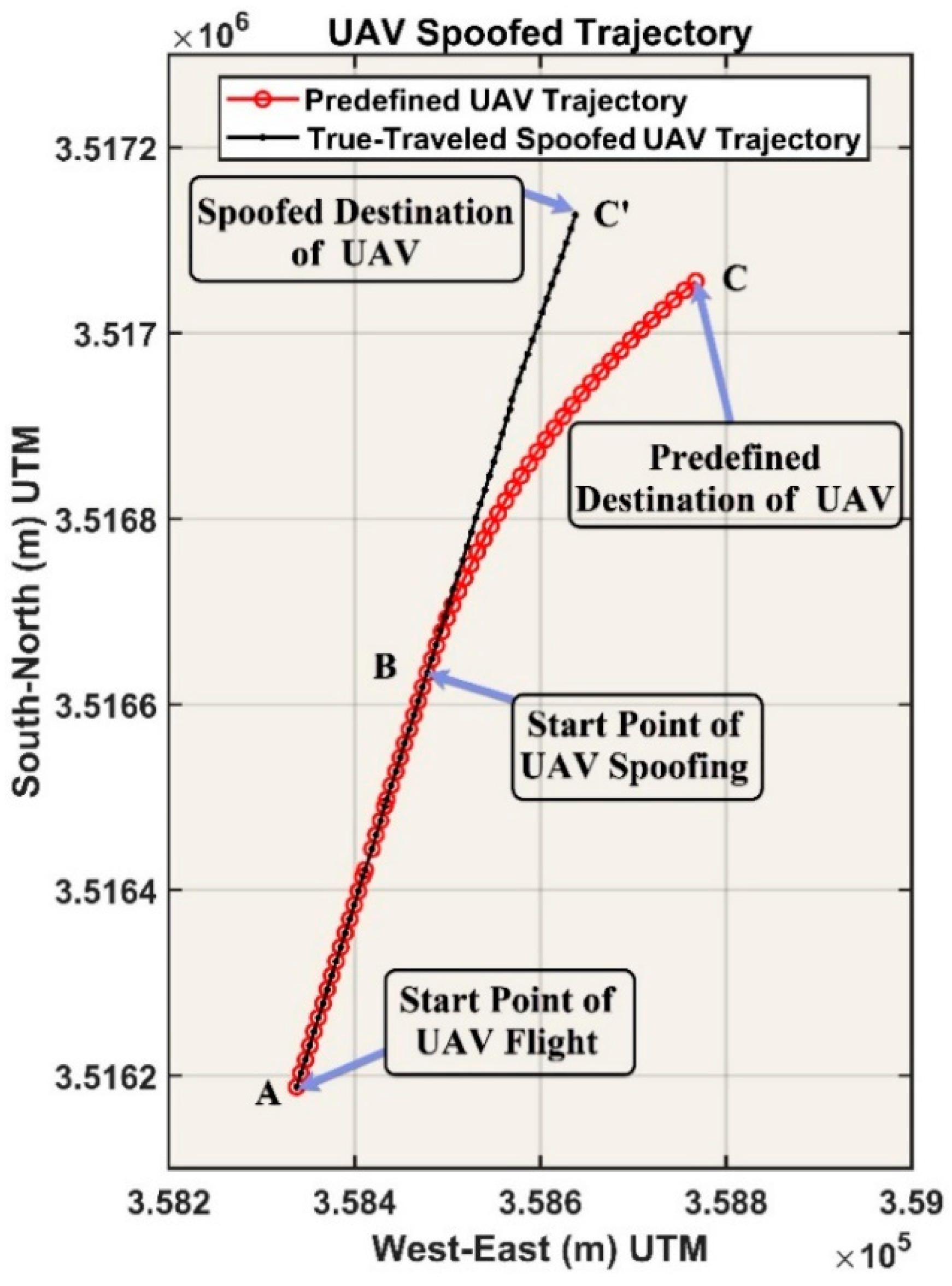
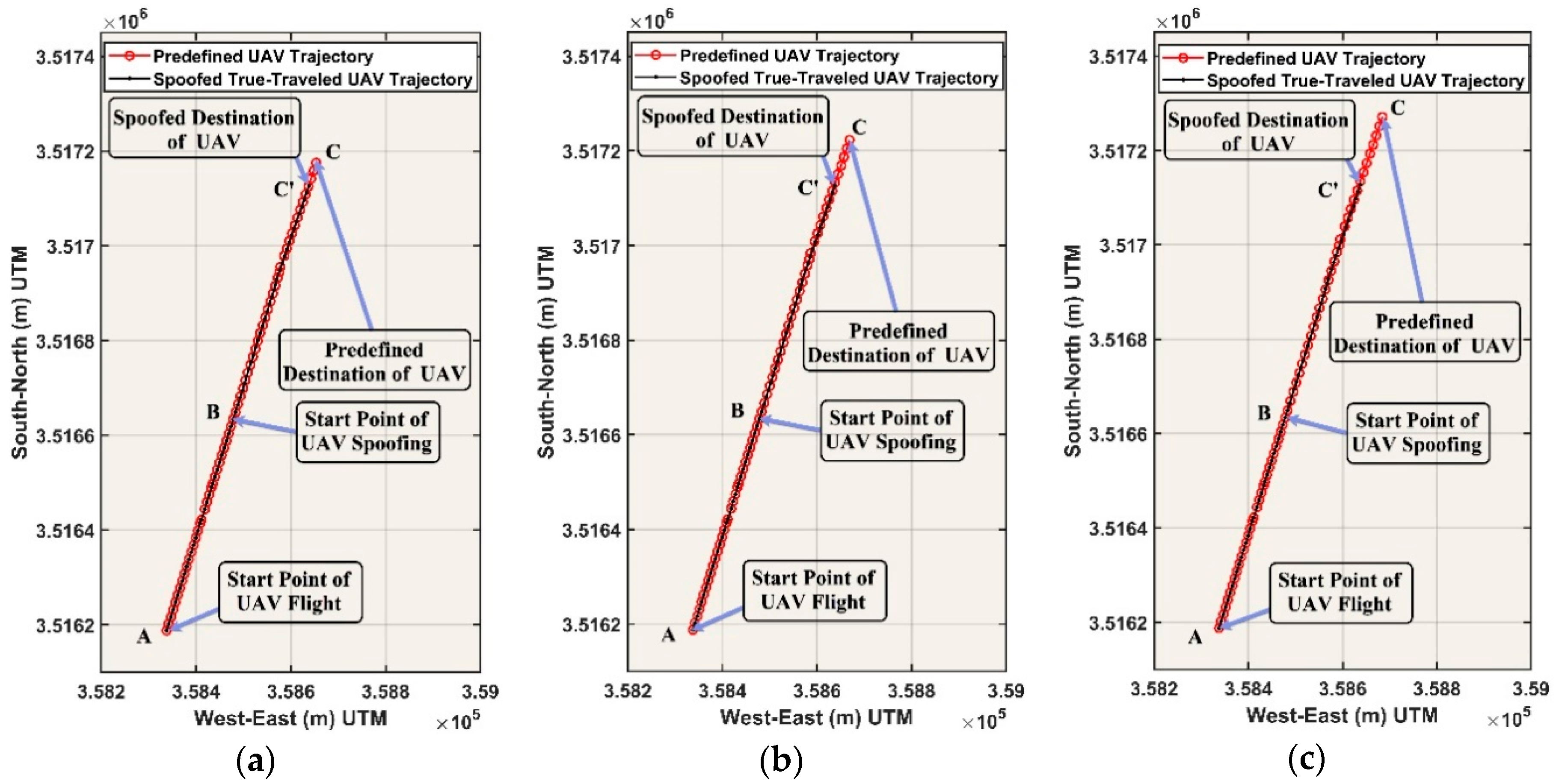
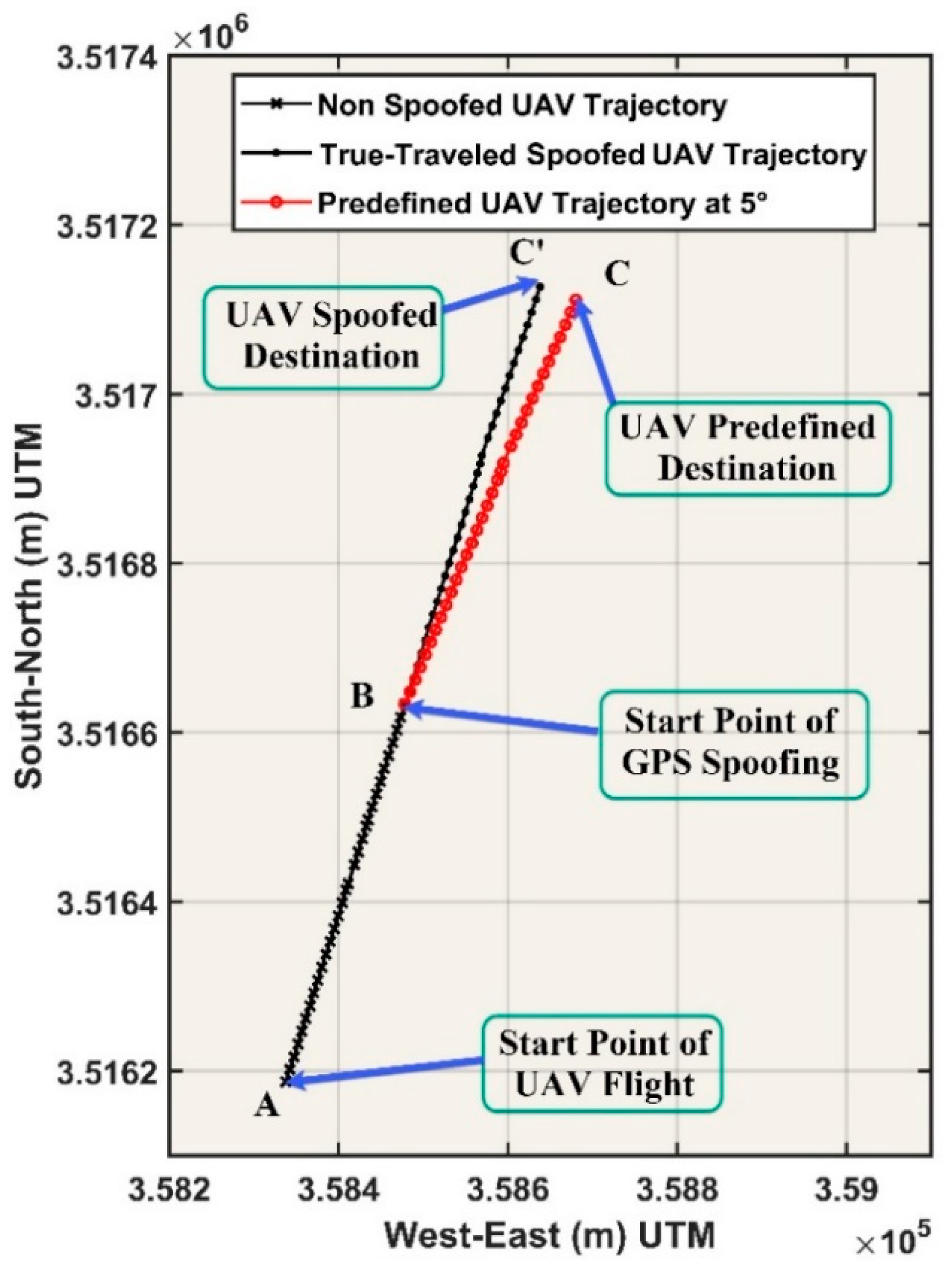
In this section initially, we describe the GPS spoofing effects on the UAV positioning and then our vision-based UAV spoofing detection method is presented. In the case of SRB GPS spoofing, the spoofer is aware of the instantaneous location and predefined trajectory and destination of the UAV. Additionally, the spoofer can generate and broadcast fake GPS signals such that the trajectory created from fake GPS positions coincides with the predefined trajectory of the UAV. As a result, while the positions obtained from the spoofed GPS signals show the predefined UAV trajectory, the spoofed UAV follows another fake trajectory and is guided to a fake destination. Thus, the actual trajectory of the UAV and consequently the captured images from this trajectory will not conform to the predefined trajectory of the UAV. Hereafter, we call the actual trajectory followed by the spoofed UAV the true-travelled spoofed UAV trajectory.
The proposed vision-based UAV spoofing detection method relies on the UAV camera, which is a passive sensor and its performance and images are not altered by the fake GPS signals. A piece of information which can be extracted from UAV images is the relative trajectory of UAV using VO. Additionally, UAV images are usually geotagged using GPS positions. In the occurrence of the GPS spoofing, fake GPS positions are used in the geotagging of UAV images. The proposed vision-based UAV spoofing detection stands on the comparison of two flight trajectories, which are simultaneously determined for the UAV from two different positioning methods: the first trajectory is obtained from GPS positions and the second trajectory is obtained from UAV images using VO.
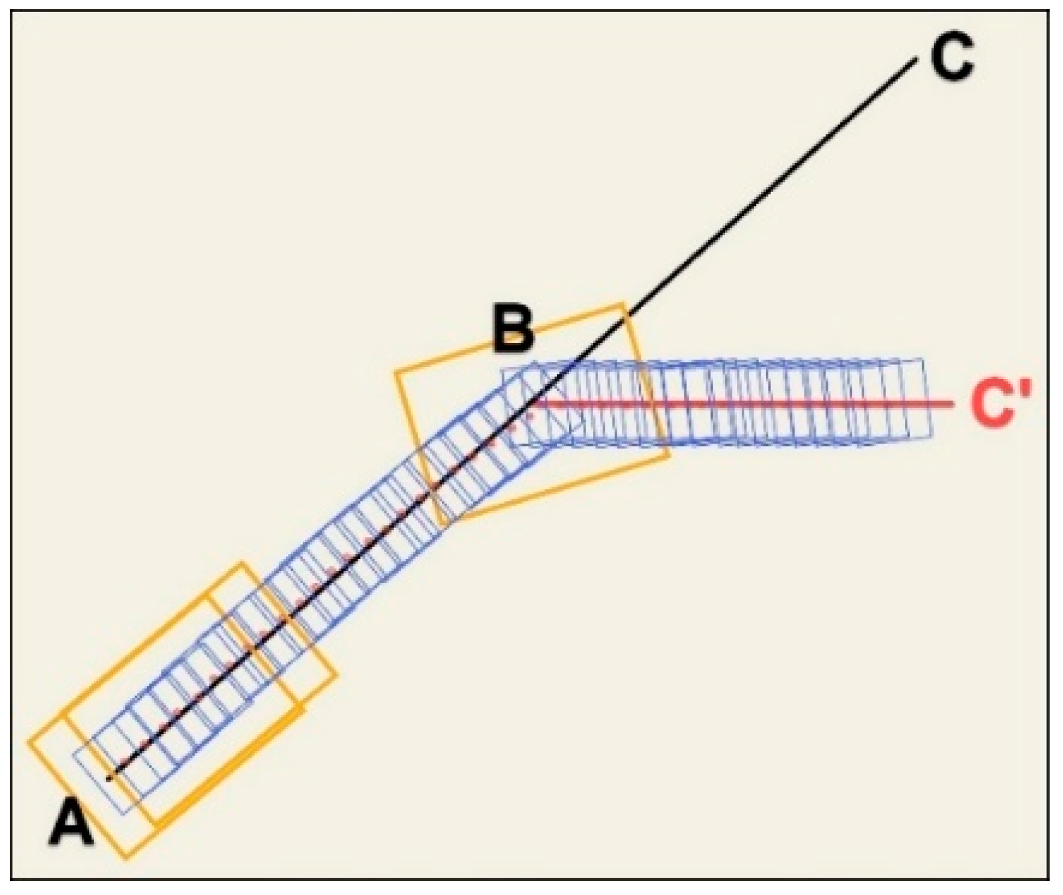
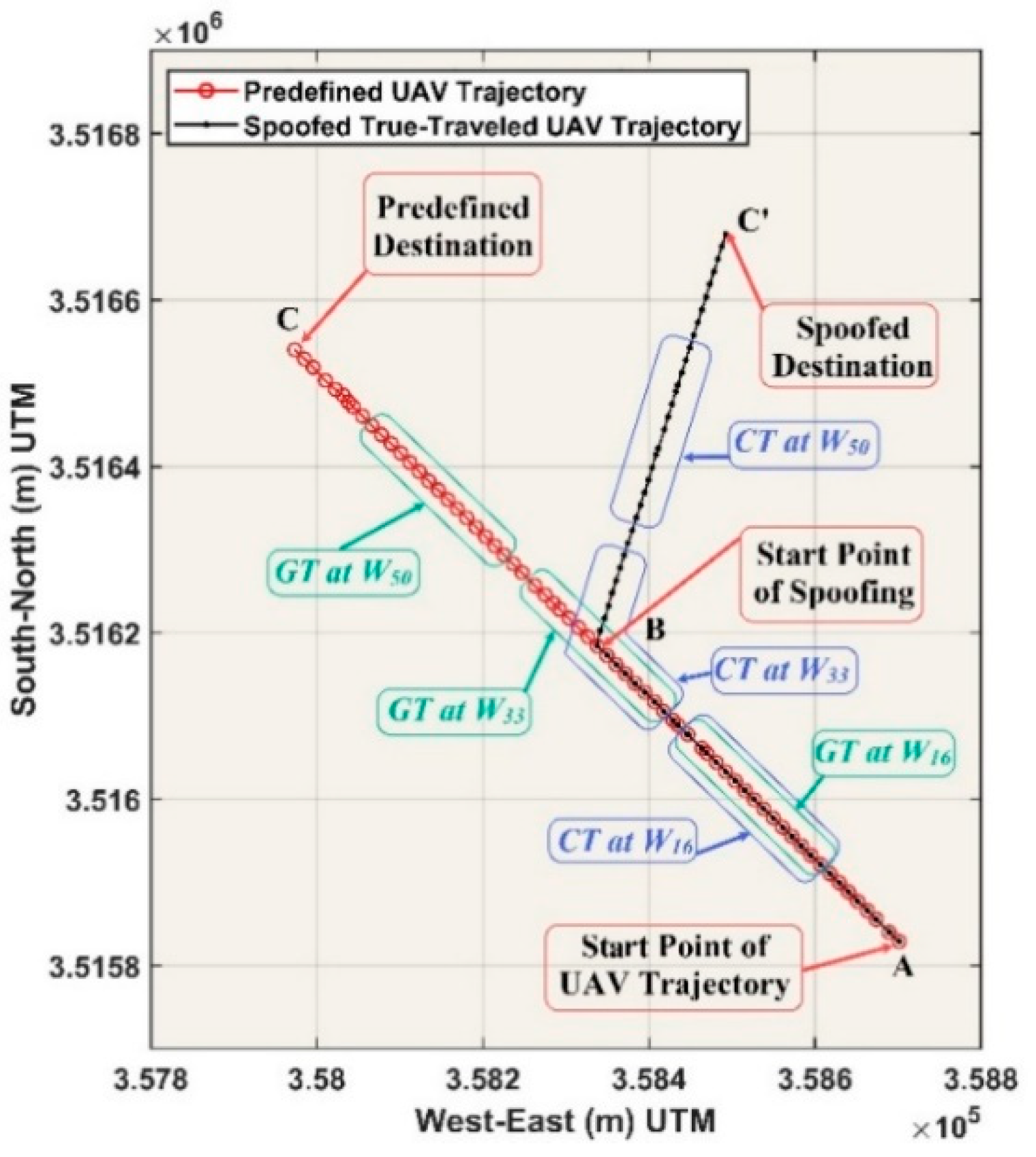
When the UAV is spoofed, the location, shape, length, and other characteristics of the UAV trajectory extracted from GPS positions do not adapt with the characteristics of the true-travelled spoofed UAV trajectory obtained from UAV images using VO. Assume the line of ABC in Figure 1 is the predefined UAV trajectory and points A and C are its flight start and predefined destination points. Suppose that when the UAV reaches point B, it is spoofed by invaders using GPS spoofing. Therefore, the UAV will be departed from its predefined trajectory and will run into line BC’ instead of line BC. As mentioned, in the case of SRB level of GPS spoofing, the spoofed GPS positions still show that the UAV follows its predefined trajectory (i.e., line BC), while the true-travelled trajectory of the UAV is line BC’. Therefore, in Figure 1, the line of ABC’ is the true-travelled spoofed UAV trajectory. The comparison of these trajectories is used here for the UAV spoofing detection. Although this comparison can detect UAV spoofing, it cannot specify the time and location of UAV spoofing. To overcome this shortcoming, instead of comparing the entire UAV’s predefined and true-travelled spoofed trajectories, a moving window-based approach is used to locally compare these trajectories within each window. For this purpose, a window along the UAV trajectory is slid position-by-position and in each imaging position of UAV selects k geotagged images. Here, k is the size of the moving windows. In Figure 1, the yellow rectangles in the beginning and middle parts of the trajectories are examples of moving window. In each window, two sub-trajectories of the UAV can be extracted: the first sub-trajectory is extracted from the GPS positions (true or spoofed), which are used in geotagging of UAV images. The second sub-trajectory is extracted from UAV images using VO. If there is no UAV spoofing, these sub-trajectories will be similar. By comparison of these sub-trajectories, it is possible to precisely detect the time and location of the UAV spoofing. These sub-trajectories can be compared directly using a metric distance or indirectly using a trajectory descriptor which describes the trajectory by a feature vector that reflects the various characteristics of trajectory. In the following, the components of this vision-based method are fully described.

2.1. Trajectory Extraction Using VO

The trajectory of a moving point (e.g., a UAV), T, is a sequence of the ordered pairs of ( t i , P i ) [43] as in Equation (1). In this Equation, P i is the position vector of the point at the time of ti, and n is the number of positions in T or the length of T:
T = { ( t 1 ,   P 1 ) , , ( t n , P n ) }
At the i-th position of the UAV and within a moving window of Wi, two sub-trajectories with a length of k (k is the window size) can be assigned to the UAV. This window moves along the UAV trajectory and in each i-th position of UAV, k geotagged images will be selected from the image number of i − (k − 1)/2 to i + (k − 1)/2. Inside Wi, the first sub-trajectory is extracted from the GPS positions of Gi−(k−1)/2 to Gi+(k−1)/2 which are used in the geotagging of UAV images (Equation (2)). This sub-trajectory is called the GPS trajectory and, in the following, is denoted as GTi. Additionally, the second sub-trajectory is extracted from the UAV camera positions of Ci−(k−1)/2 to Ci+(k−1)/2 within Wi, which are computed using VO (Equation (4)). This sub-trajectory is called the Camera Trajectory and, in the following, is denoted as CTi (Equation (3)):
G T i = { ( t j ,   G j ) , , ( t j + k 1 , G j + k 1 ) } ; j = i k 1 2 : i + k 1 2
C T i = { ( t j ,   C j ) , , ( t j + k 1 , C j + k 1 ) } ; j = i k 1 2 : i + k 1 2
The extraction of GTi within each Wi is easy but the achievement of CTi using VO requires more computations. VO is the process of estimating the ego-motion of an agent (e.g., the UAV), using only the input of a single or multiple cameras attached to it [44]. The relative position of the camera in VO can be estimated in an appearance-based or feature-based approach. In the appearance-based method, the intensity values, in a template matching approach, or the optical flow values are used for pose estimation [45]. In the feature-based methods, distinct point features extracted and described and then used for point matching and relative pose estimation between two images that are dependent to image texture [46]. As in the proposed method, only the relative sub-trajectories of the UAV are used; thus, a geometric feature-based monocular VO [47] approach with a calibrated camera was used for UAV trajectory computation. Additionally, a SIFT (Scale-Invariant Feature Transform) [48] operator was used to point feature extraction and description to match the corresponding points and compute the relative orientation parameters.
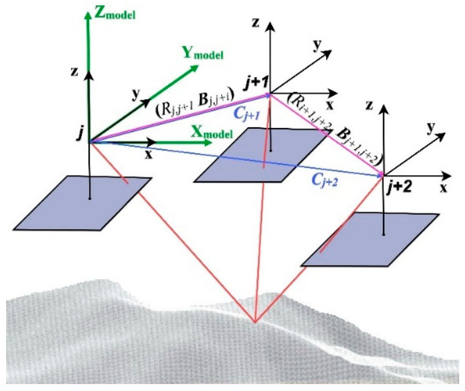
For the computation of CTi, within each Wi, the relative orientation, ( R j , j + 1 ,   B j , j + 1 ) , parameters between successive stereo images of I j and I j + 1 need to be estimated. Here, R j , j + 1 is the relative rotation matrix of camera at the position j + 1 concerning the camera at the position j, and B j , j + 1 is the relative position vector of the camera at the position j + 1 concerning the camera at the position j, as shown in Figure 2. Then, all relative camera positions within Wi have transformed into the model coordinate system of the first stereo images using Equation (4) [36,49].
C j = 0 ; j = p = i k 1 2 C j = B j 1 , j ; j = p + 1 C j = C j 1 + S p , j 2 M p , j 2 B j 1 , j ;   p + 2 j i + k 1 2 S p , j 2 = λ p , p + 1 λ j 2 , j 1 M p , j 2 = R p , p + 1 R j 2 , j 1
In Equation (4), C j is the position vector of j-th image within Wi, λ j 2 , j 1 is the scale factor of the distance transformation from the stereo model of j 1 to the stereo model of j 2 , R j 2 , j 1 is the relative rotation matrix of the camera at the position j 1 concerning the camera at the position j 2 , S p , j 2 is the scale factor of distance transformation from stereo model of j 2 to the first stereo model of j = p , and M p , j 2 is the relative rotation matrix of camera at the position j 2 concerning the first camera at the position j = p .
The most important defect of VO, especially in the long-range VO, is the cumulative error in the estimation of camera position. This will cause a drift in the estimated trajectory from the real one, which is unbounded. This error increases as the length of the trajectory is increased. By applying the window-based approach in the extraction of the UAV sub-trajectories of CTis, the drift error of VO was controlled in this paper. Additionally, to reduce this error, the sliding sparse bundle adjustment [44,50], as an effective technique in the reduction of this error, was implemented.

2.2. Coordinate Transformation

To detect the UAV spoofing within the window Wi, two sub-trajectories of CTi and GTi must be compared. However, it is not possible to compare them directly. This is due to the different coordinate systems of these sub-trajectories. Thus, before comparing them, these sub-trajectories should be transformed into the same coordinate system. GTi is usually expressed in a ground coordinate system, such as WGS84 (World Geodetic System 1984) or UTM (Universal Transverse Mercator), and, as aforementioned, CTi is stated in the model coordinate system of the first stereo images within Wi. These coordinate systems have different origins, scales, and axes orientation. Moreover, since the accuracy of height positioning by GPS is lower than the accuracy of the planimetric positioning by GPS, in this paper, only the planimetric trajectories were used. In Wi, the coordinate system of GTi is transformed into the coordinate system of CTi, using a two-dimensional (2D) conformal model (Equation (5)):
T G j = X o + ρ R ( φ ) G j
where φ is the rotation angle, ρ is the scale factor and X o is the translation vector of the coordinate system of GTi concerning the coordinate system of CTi. In this equation, T G j is the transformed position vector of G j in Equation (2). To obtain parameters of this model (i.e., φ , ρ , and X o ), the corresponding coordinates of the first and last images within Wi from GPS and VO were used. After transformation, the transformed GTi is denoted as TGTi, as in Equation (6):
T G T i = { ( t j ,   T G j ) , , ( t j + k 1 , T G j + k 1 ) } ; j = i k 1 2 : i + k 1 2

2.3. Comparison of Camera and GPS Sub-Trajectories

The comparison of CTi and TGTi within Wi can detect the UAV spoofing. This comparison can be done directly or indirectly using some dissimilarity measures. In this article, for direct comparison, the Sum of Euclidian Distances between Corresponding Points (SEDCP) of CTi and TGTi is used. Additionally, for indirect comparison, the angle distance and taxicab distance between the HOD (Histogram of Oriented Displacements) trajectory descriptors of CTi and TGTi are used.

2.3.1. Direct Comparison

The direct comparison of CTi and TGTi within Wi can be done using SEDCP, as in Equation (7). In this equation, d ( T G j , C j ) is the Euclidian distance between T G j and C j :
S E D C P ( C T i , T G T i ) = j = i k 1 2 i + k 1 2 d ( T G j , C j )
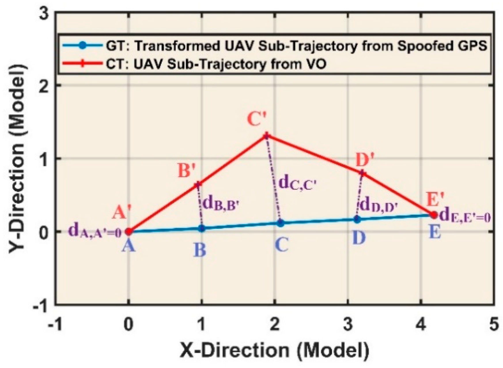
Figure 3 shows the Euclidian distances between the corresponding points of CTi and TGTi within a five-point window of Wi. In this figure, point C’ is the beginning point of UAV spoofing and its redirection point due to GPS spoofing which is recorded in CTi.

2.3.2. Indirect Comparison

The indirect comparison of CTi and TGTi can be done using their HOD trajectory descriptors. The HOD trajectory descriptor was introduced in [
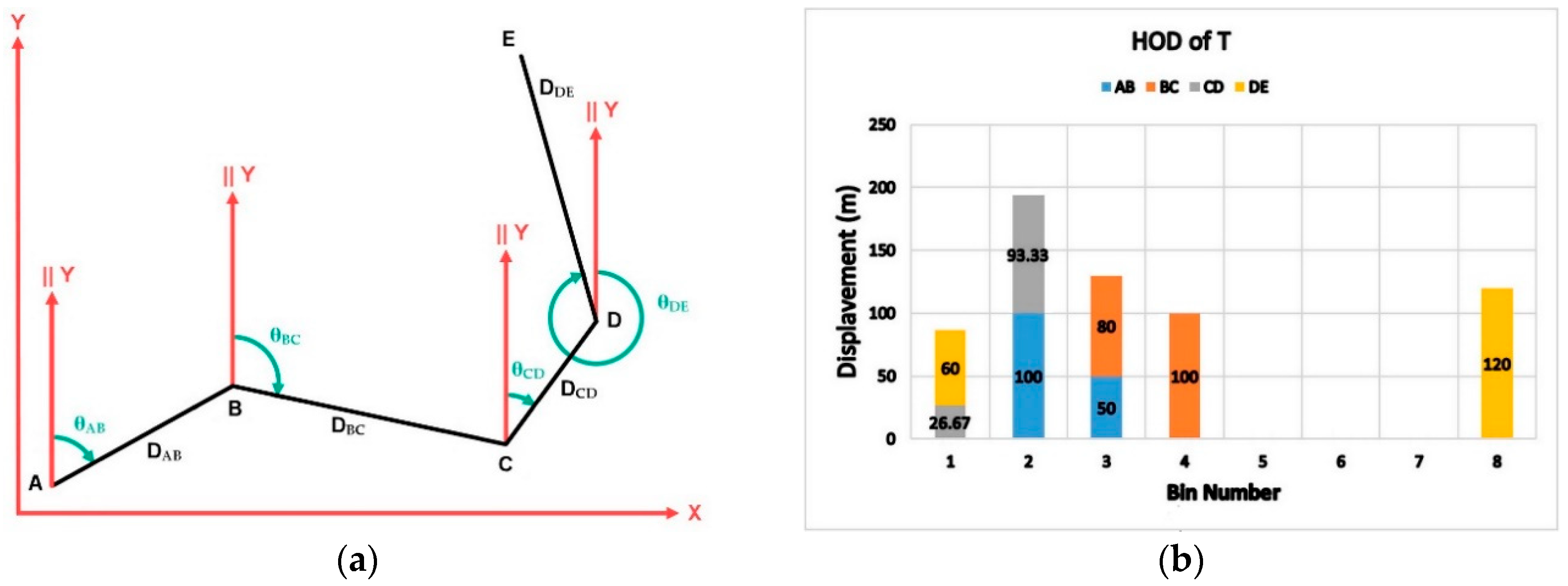
51] to describe the trajectory of body joints and to recognize the human actions from the Kinect point cloud. The HOD trajectory descriptor is a histogram that its bins record the displacement amount of the moving object in different directions between 0° to 360°. The bins number (BN) of the HOD determines the angular resolution or the bin interval (BI) of HOD (Equation (8)). For example, if BN is set to eight, its bin interval (BI) will be equal to 45° and its bins indicate the directions at the angles of 0°, 45°, …, and 315° (Figure 4).
In conventional HOD, distance D j , j + 1 with the azimuth angle (the direction angle of D j , j + 1 concerning Y-axis) of θ j , j + 1 (Equation (9)) is assigned to its nearest bin in terms of the angular distance, and then, the sum of the assigned distances to each bin is computed. In this paper, a modified HOD was constructed by dividing each distance of D j , j + 1 between its two nearest bins in terms of the relative angular distance of θ j , j + 1 with the angles of those bins. In Equation (9), ( x j , y j ) is the coordinates of the j-th point. The portion of each bin from each distance of D j , j + 1 is computed according to Equation (10). The two nearest bins of D j , j + 1 are determined using Equations (11) and (12):
B I = 360 ° B N
θ j , j + 1 = atan 2 1 ( ( x j + 1 x j ) , ( y j + 1 y j ) )
b i n P o r t i o n = D j , j + 1 × ( 1 | θ j , j + 1 ( B N 1 ) × ( B I ) | ( B I ) )
F i r s t B N = θ j , j + 1 B I + 1
S e c o n d B N = F i r s t B N + 1
As illustrated in Figure 4, the HOD is dependent on the Y-axis of coordinate system in computing the azimuth angle of θ j , j + 1 . Hence, to compare CTi and GTi with their HOD descriptors, GTi should be transformed into the coordinate system of CTi. Figure 5a and Figure 5b, respectively, show an example of a general trajectory, T, and its HOD trajectory descriptor. Furthermore, Table 1 shows the values of D j , j + 1 and θ j , j + 1 , their first and second nearest bin numbers and the portion of each side of T on these bins. Additionally, Table 2 shows the portion of each side of T in each bin. The last row in Table 2 is the modified HOD trajectory descriptor of T and is the sum of the portion of sides in each bin.
For an indirect comparison of CTi and TGTi using their HOD trajectory descriptors, two dissimilarity measures are proposed here. First, the Angle Distance between HODs (HOD_AD), and second, the Taxicab Distance between HODs (HOD_AD) of these sub-trajectories were used to compute their dissimilarities (Equations (13) and (14)). In these equations, a and b , respectively denote the HOD trajectory descriptors of CTi and TGTi, and a i and b i are the i-th components of a and b :
H O D _ A D ( a , b ) = 1 π × c o s 1 ( a | b a b )
H O D _ T D ( a , b ) = i = 1 p = B N | a i b i |

2.4. Vision-Based UAV Detection

Figure 6 shows the steps of the proposed vision-based method for UAV spoofing detection, which is briefly described in seven steps in Figure 6.
Step 1
Initially, the size of moving window (k), the threshold of the used dissimilarity measure (Th), and the threshold of UAV spoofing declaration (k/2) are determined. The threshold of dissimilarity measure is used in the determination of fake GPS positions and the threshold of UAV spoofing declaration is used in declaring of UAV spoofing. The threshold values of SEDCP, HOD_AD and HOD_TD dissimilarity measure are obtained by a sensitivity analysis that is fully described in Section 3.7. Additionally, the threshold of UAV spoofing declaration is set to k/2.
Step 2
In this step, at each i-th UAV position, k images from UAV flight path, from the image number of i-(k-1)/2 to i+(k-1)/2, are selected using a moving window of Wi.
Step 3
In step 3, using the selected images and their corresponding GPS positions within the window Wi, two corresponding CTi and GTi sub-trajectories are calculated.
Step 4
In this step, the coordinate system of GTi is transformed into the coordinate system of CTi.
Step 5
Here, the dissimilarity measure between CTi and TGTi is computed.
Step 6
In this stage, the computed dissimilarity measure between CTi and TGTi within the window Wi is compared with the threshold value, Th. If the value of dissimilarity measure exceeds Th, the GPS position at point i, will be recognized as a fake position.
Step 7
Finally, based on the results of the previous step, the decision is made to declare the UAV spoofing based on the given threshold.

3. Experiments and Results

3.1. Data

To evaluate the proposed vision-based approach for UAV spoofing detection, 97 images of a UAV photogrammetry project from Golgir village of Masjed Soleiman city in southwestern Iran were used. Figure 7, shows a Google Earth view of Golgir village and the flight lines of this UAV photogrammetry project which are used in the implementation of different scenarios of the proposed approach.
A DJI-FC6520 digital camera with the focal length of 12 mm and the image size of 5280 by 3956 pixels and GSD (Ground Sample Distance) of 0.03 m was used in this project. The overlap area between the successive images is about 80% and the imaging height above the earth surface is about 110 m. The length of the trajectory from the used images is about 2300 m. All images were geotagged using GPS positions during the flight with an accuracy of ±1.5 m. Figure 8 shows two successive stereo images of the dataset.

3.2. GPS Spoofing Simulation

In Section 1, some studies about the successful spoofing of civilian UAVs using the GPS spoofing are reviewed [10,11,12,13,14]. In this paper, due to the limitations in the implementation of GPS spoofing, the occurrence of GPS spoofing in the SRB spoofing level was simulated. The UAV spoofing due to the GPS spoofing in the SRB spoofing level means that the spoofer knows the UAV location, destination, velocity, and its predefined trajectory. Thus, the spoofer can generate and propagate fake GPS signals so that the fake GPS positions generated from the spoofed signals coincide with the predefined UAV trajectory, while UAV is directed to another spoofed trajectory. The SRB spoofing level is the most difficult mode of GPS spoofing for detecting and mitigating. Additionally, it is assumed that the spoofer generates fake GPS signals so that the UAV velocity is not significantly changed. As a result, the distance travelled by UAV at the time of spoofing will be equal to its travelled distance in the case of that no GPS spoofing exists. This will make it almost impossible to detect the UAV spoofing using the comparison of UAV velocity and its travelled distance from the spoofed GPS and other sensors such as the camera.
In this research, the simulated spoofed UAV positions are selected from the available GPS positions of geotagged UAV images in the flight lines of Golgir UAV photogrammetry project (Figure 7b). Additionally, corresponding to these spoofed GPS positions (i.e., the predefined flight line), another flight line from Golgir UAV photogrammetry project is considered to be the true-travelled spoofed UAV trajectory.

3.3. UAV Spoofing Detection: First Scenario

Figure 9 schematically shows the first scenario of UAV spoofing. The images and GPS positions in the predefined and in the true-travelled spoofed UAV trajectories are selected from the flight lines of the Golgir UAV photogrammetry project (i.e., the lines of ABC and ABC’ in Figure 7b). As these are selected from the same UAV photogrammetry project, there is not a significant difference in UAV velocity over these flight lines.
In this scenario, point A was assumed as the starting point of the UAV trajectory and point B was assumed as the starting point of the UAV spoofing, which was applied at the imaging position number of 33 (Figure 9). The predefined destination of the UAV was point C; however, when the spoofing was applied, the UAV will be redirected to point C’. Line BC in Figure 9 was constructed from the faked GPS positions, and line ABC (in red-circle markers) was considered to be the predefined UAV trajectory. Additionally, line ABC’ in Figure 9 (in black-dot markers) was considered to be the true-travelled spoofed UAV trajectory, which includes the UAV images. It was assumed that no spoofing has occurred in segment AB. Thus, the predefined UAV trajectory and the true-travelled spoofed UAV trajectory coincided in this segment. Within each window of Wi, the GPS positions of the geotagged UAV images were used to construct GTi, and the corresponding UAV images were used to construct CTi. When spoofing occurred at point B, the GPS measurement during the flight of UAV over line BC’ should demonstrate line BC (i.e., predefined flight line). Hence, the GPS positions in line BC were considered to be the fake GPS positions, which correspond to the UAV images in line BC’; Line BC’ is the true-travelled spoofed UAV trajectory. The GPS positions of line BC are used in the construction of GTis and the UAV images of line BC’ are used in the construction of the corresponding CTis using VO.

Results of the First Scenario

In this scenario, to detect the UAV spoofing, the size of the moving window of Wi was set to 9, 15, and 21. Figure 10 shows the values of three dissimilarity measures used for UAV spoofing detection within each window of Wi.
In Figure 10, the horizontal axis is the imaging position number of UAV in its flight trajectory and the vertical axis shows the values of the dissimilarity measure. In Figure 10a, when the imaging positions from VO are in coincidence with the GPS positions within the moving window, the HOD_AD is close to zero. In this scenario, this situation occurs up to the UAV imaging position number 26 for a window size of 15. Until this position, the moving window does not contain any fake GPS position from the line BC’. In this region, there is no significant difference between CTi and TGTi. However, by reaching the window to position number 27, and by entering the first fake GPS position (i.e., position number 34) into the window, the value of the HOD_AD dissimilarity measure begins to rise (Figure 10a). The maximum value of the HOD_AD dissimilarity measure has occurred at imaging position number 33, which is the starting point of UAV spoofing. As depicted in Figure 9, the maximum difference between CTi and TGTi has occurred at this point within the window W33. After passing position number 41, all imaging positions in the true-travelled spoofed UAV trajectory and all fake GPS positions in the predefined UAV trajectory are located in a straight direction within the moving windows (e.g., CT50 and GT50 at W50 in Figure 9). Therefore, HOD_AD becomes close to zero again, because, in these positions, TGTi coincides with CTi. This pattern can be observed in window sizes 9 and 21, as demonstrated in Figure 10a. Additionally, the results of this scenario from HOD_TD and SEDCP dissimilarity measures are presented in Figure 10b and Figure 10c, respectively. The results demonstrate that all HOD_AD, HOD_TD, and SEDCP have a good sensitivity to the instant change in the direction of UAV due to the spoofing. Additionally, the values of HOD_TD and SEDCP considerably increase as the window size increases from 9 to 15 and 21.
As mentioned before, point B or the position number of 33 is the starting point of UAV spoofing and point C’ is the spoofed destination of UAV at the position number of 66 (Figure 9). In this regard, 33 fake GPS positions have occurred during the UAV spoofing. To detect the spoofing occurrence, the threshold values of HOD_AD, HOD_TD, and SEDCP are set to 0.002, 0.13, and 0.31, respectively. The process of the determining of these thresholds is described in Section 3.7. The number of fake GPS positions detected by the proposed method using these dissimilarity measures at three sizes of the moving window is given in Table 3.
The obtained results demonstrate that all dissimilarity measures, detect the UAV spoofing at its beginning, particularly in the case of using a window size of 9. Therefore, the proposed method through these dissimilarity measures can correctly detect the location and time of UAV spoofing.
In general, by increasing the window size, the numbers of the detected fake GPS position by the proposed method are increased. Moreover, the sensitivity of SEDCP to the UAV spoofing up to the fake destination (i.e., the position number of 66) can be observed in Figure 10c. Compared to HOD_AD and HOD_TD, the SEDCP dissimilarity measure can successfully detect all fake GPS positions even after the position numbers of 37, 40, and 43 in all sizes of the moving window. After these positions, all imaging positions in the true-travelled spoofed UAV trajectory and all fake GPS positions in the predefined UAV trajectory are located in a straight direction within the moving window. A closer look at the positions of GPS and camera in lines BC and BC’ reveals that there is a little difference in UAV velocity between these lines because the images and GPS positions are selected from two different flight lines of Golgir UAV photogrammetry project. This shows that SEDCP is more sensitive to the slight changes in UAV velocity due to the GPS spoofing. Therefore, to monitor the UAV spoofing, SEDCP is more valuable due to its sensitivity to the changes in the UAV direction and velocity caused by the GPS spoofing.

3.4. UAV Spoofing Detection: Second Scenario

Figure 11 shows that the second scenario of UAV spoofing aims to evaluate the effects of redirection points. In this regard, the line of ABCDE is considered as the predefined UAV trajectory in which points C and D are redirection points of UAV. Additionally, line ABC’ is considered to be the true-travelled spoofed UAV trajectory. Point A is the starting point of UAV flight and point B is the starting point of UAV spoofing at the imaging position number of 33. The predefined destination of UAV is point E; however, the spoofed UAV is redirected to point C’ at the imaging position number of 97. Similar to the first scenario, in this scenario, the UAV images in the true-travelled spoofed UAV trajectory and the fake GPS positions in the predefined UAV trajectory are selected from the flight lines of Golgir UAV photogrammetry project.
Similar to the first scenario, the size of the moving window was set to 9, 15, and 21. Figure 12 shows the values of the dissimilarity measure. Considering this figure, the first maximum value of dissimilarity measures was obtained at the starting point of UAV spoofing, at position number 33 (i.e., point B in Figure 11). Additionally, two additional maximum values were achieved at the UAV redirection points at position numbers 55 and 76, at points C and D. This condition was true for all dissimilarity measures and window sizes. The reason for the appearance of these maximum values at the redirection points is the difference that exists between the shape of CTi and GTi at these points. Therefore, the proposed method is sensitive to the existence of any redirection point. In particular, the performance of SEDCP and HOD_TD in the detection of UAV spoofing in these redirection points was better than the performance of HOD_AD. Moreover, SEDCP demonstrates superior results, since it can efficiently discriminate between the normal and spoofed states of UAV. Generally, the values of SEDCP are bigger than the values of HOD_TD and SEDCP is a suitable dissimilarity measure compared to HOD_TD. The impact of window size in the UAV spoofing detection and at the beginning of UAV spoofing is important. In other words, as the size of the window becomes smaller, it gets more sensitive and can detect UAV spoofing earlier, namely, at the beginning. Moreover, the obtained results demonstrate that the monitoring time of UAV spoofing is dependent on the window size. When the size of the window increases, the fake GPS positions remain inside the window for a long time. In other words, the response time to spoofing occurrence in the larger size of the window (e.g., 21) is longer than the response time in the smaller window size (e.g., 9). Table 4 shows the number of the detected fake GPS positions using the proposed dissimilarity measures at three sizes of the moving window. In this scenario, SEDCP successfully detected the UAV spoofing occurrence in the window sizes of 15 and 21 from the starting point of spoofing up to the end of it.

3.5. UAV Spoofing Detection: Third Scenario

In this scenario, a flight line of Golgir UAV photogrammetry project was selected as the true-travelled spoofed UAV trajectory. Corresponding to this trajectory, a predefined UAV trajectory was designed as a curve instead of a straight line. This curve demonstrates the case in which the UAV direction in the predefined UAV trajectory changed incrementally with a rate of 1° from one imaging position to the next. Figure 13 shows this scenario. Point A was the starting point of the UAV trajectory and point B was the starting point of UAV spoofing, which was applied at position number 31. Additionally, point C’, at position number 64, was considered to be the spoofed destination of the UAV (Figure 13). In this regard, 32 fake GPS positions occurred during the UAV spoofing. The results of this scenario at the window size of 9, 15, and 21 are presented in Figure 14. Table 5 shows the numbers of fake GPS positions in this scenario, which were detected by the proposed dissimilarity measures at different window sizes.
As shown in Figure 14, all the used dissimilarity measures have small values in the small window size, such that the UAV spoofing detection is not reliable compared to the large window size. Additionally, in this scenario, the values of the dissimilarity measures incrementally increase after the starting of UAV spoofing. This result demonstrates that the UAV spoofing can be monitored for a long time during the incremental UAV spoofing. However, the values of SEDCP and HOD_TD in the large window size have an acceptable amount for UAV spoofing detection.

3.6. UAV Spoofing Detection: Fourth Scenario

This scenario was designed to demonstrate the efficiency of the proposed method in the UAV spoofing detection in which only the UAV velocity has changed due to the GPS spoofing and there is no change in the flight direction. In this scenario, the flight line of the Golgir UAV photogrammetry project, which was used in the third scenario, was selected as the true-travelled spoofed UAV trajectory. Additionally, it was assumed that the UAV spoofing occurred after imaging position number 31. Corresponding to this trajectory, three predefined UAV trajectories were designed; in them, the UAV velocities after the spoofing point were 1.1, 1.2, and 1.3 times the true velocity of the spoofed UAV. These trajectories are depicted in Figure 15. In this figure, point A is the starting point of the UAV trajectory and point B is the starting point of UAV spoofing. Additionally, points C and C’, at position number 64, are, respectively, considered to be the predefined and spoofed destinations of UAV. In this regard, 32 fake GPS positions occurred during UAV spoofing. The results of this scenario at a window size of 9 and three different velocities of the spoofed UAV are presented in Figure 16. As shown in Figure 16, HOD_AD and HOD_TD dissimilarity measures had values smaller than their thresholds, as they are the most sensitive to the redirections in the trajectory of the spoofed UAV. As in this scenario, there was no redirection point in the trajectory of the spoofed UAV; the values of these dissimilarity measures were close to zero and the same results were obtained for all velocities of the spoofed UAV. In contrast, the SEDCP dissimilarity measure was able to detect UAV spoofing and discriminate between different velocities of the spoofed UAV. Table 6 shows the numbers of fake GPS positions in this scenario that were detected by the proposed dissimilarity measures. It is shown in Figure 16a,b that HOD_AD and HOD_TD dissimilarity measures cannot detect any fake GPS positions, while SEDCP successfully detects more than six fake GPS positions (Figure 16c).

3.7. Sensitivity Analysis

For sensitivity analysis of the proposed method to the changes in the direction of UAV, initially, one of the flight lines of Golgir UAV photogrammetry project was selected as the true-travelled spoofed UAV trajectory (line with the black markers in Figure 17). Point A is the starting point of the UAV flight trajectory and point B is the starting point of UAV spoofing in this scenario, which was applied at position number 31. Additionally, point C’ was considered as the spoofed destination of UAV. Then, line BC’ drifted in some angles and the drifted line was considered as the predefined UAV trajectories. For this purpose, line BC’ drifted in 1°, 2°, 3°, 4°, and 5°. For clarity, only the drifted line at 5° is depicted in Figure 17. The fake GPS positions over these predefined UAV trajectories were simulated according to the UAV velocity and the imaging rate camera. To determine the optimal threshold values of the dissimilarity measures, the sensitivity analysis was conducted at the window size of 9 to obtain the minimum response of the dissimilarity measures to the changes in the direction of UAV due to spoofing. The results of this sensitivity analysis are presented in Figure 18.
As can be seen in Figure 18, there was a maximum value almost at position number 31, which was the starting position of UAV spoofing. Concerning Figure 18a,b, HOD_AD and HOD_TD were sensitive to the redirection of UAV when UAV has deviated bigger than 2°. Additionally, SEDCP can detect deviations bigger than 1°. In this regard, the maximum values of HOD_AD and HOD_TD at 3° and the maximum value of SEDCP at 2° were selected as a reliable threshold for the spoofing declaration at each window. Therefore, the threshold values of HOD_AD, HOD_TD, and SEDCP were determined to be 0.002, 0.13, and 0.31, respectively. These thresholds were applied to the result of the scenarios in Table 3, Table 4, Table 5 and Table 6 to show the capability of the proposed method in the detection of UAV spoofing.

4. Conclusions

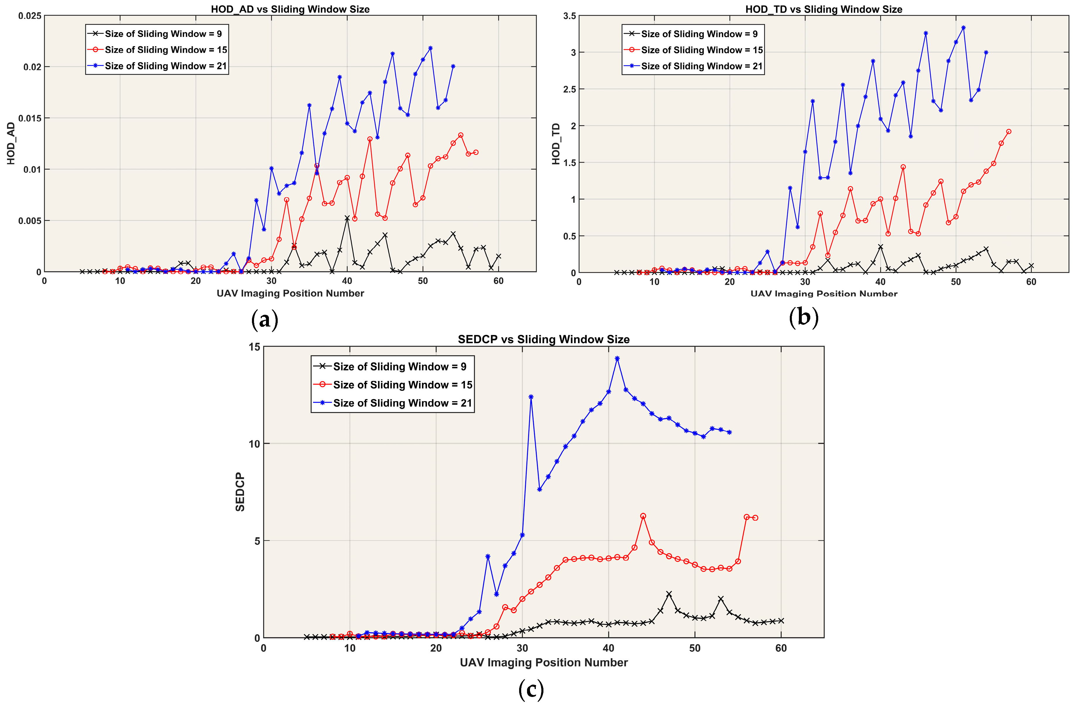
This paper introduced a vision-based UAV spoofing detection method. This method can be used in the spoofing detection of civilian UAVs, which are spoofed using GPS spoofing at the SRB spoofing level. The proposed method was based on the determination of CTi sub-trajectory using VO and GTi sub-trajectories from the GPS positions within a moving window. Three dissimilarity measures, including HOD_AD, HOD_TD, and SEDCP, were introduced to compare these sub-trajectories. To evaluate the proposed method, four scenarios were designed using the real images and GPS positions of the flight lines of Golgir UAV photogrammetry project. Moreover, based on the rate of the changes in the UAV direction due to the GPS spoofing, a sensitivity analysis was conducted at a window size of 9 to determine a suitable threshold for each dissimilarity measure.
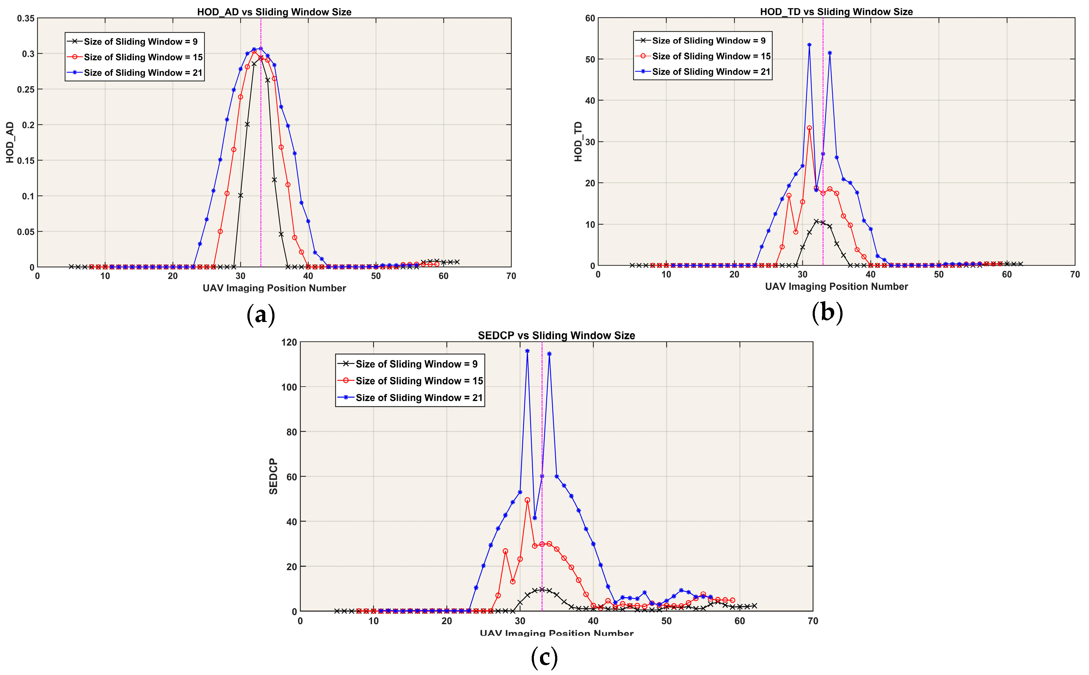
The experimental results of the first scenario demonstrated that the time and location of the UAV spoofing occurrence could be detected using the moving window approach with a time delay in about half of the window size. Consequently, UAV spoofing was successfully detected by the proposed vision-based method. Moreover, by increasing the window size, the monitoring time of UAV spoofing and the numbers of fake GPS positions that were detected by the proposed method were increased. In this experiment, SEDCP demonstrated better performance compared to HOD_AD and HOD_TD and was sensitive to the slight changes in UAV velocity due to GPS spoofing.
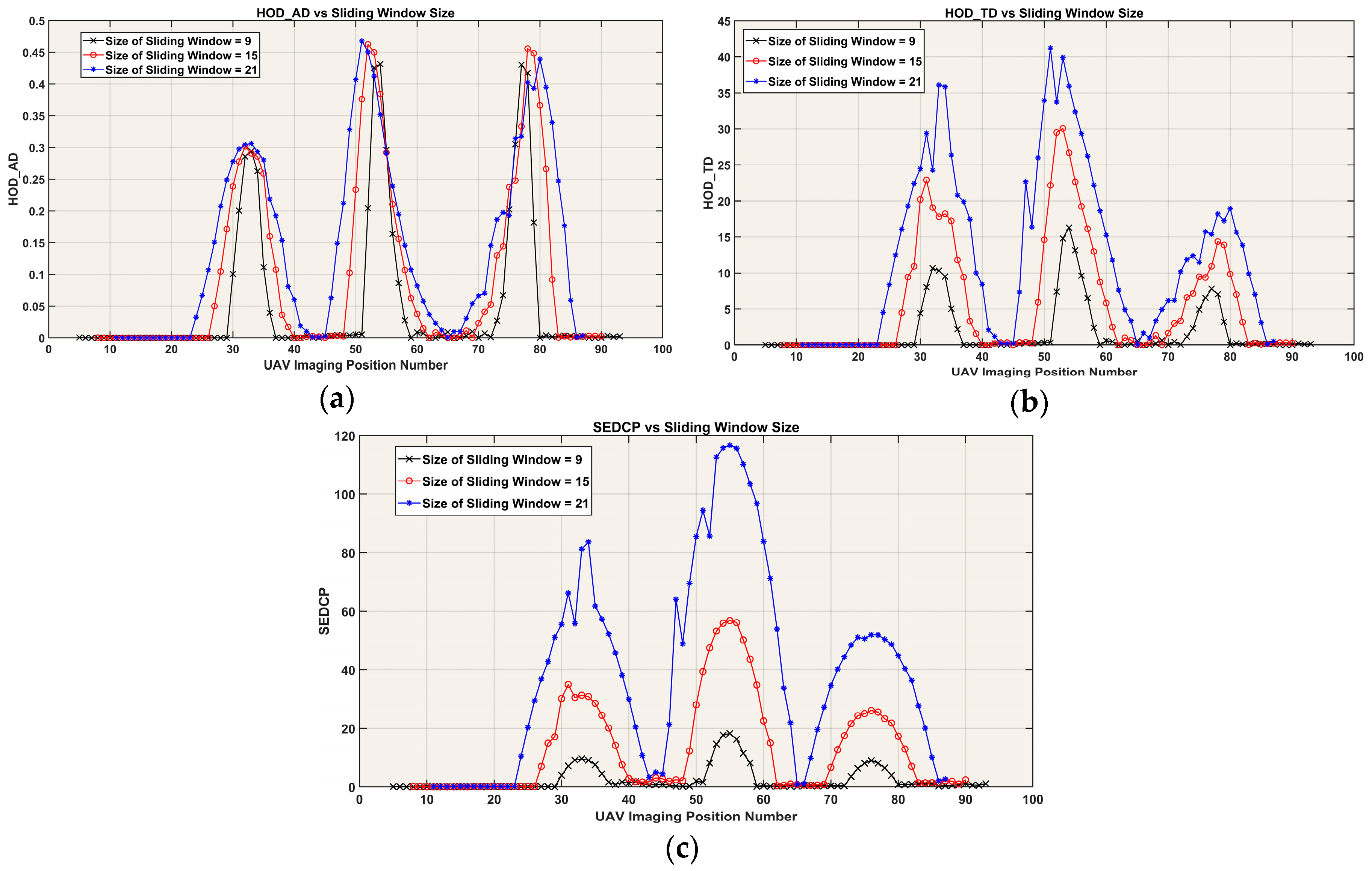
In the second scenario, which contains three redirection points, the proposed dissimilarity measures could detect the UAV spoofing at these points. The results of the second scenario showed that the proposed method is sensitive to the existence of the redirection points in the predefined or in the true-travelled spoofed UAV trajectories. In particular, the performance of SEDCP and HOD_TD in the detection of UAV spoofing in the redirection points outperformed HOD_AD. When the length of a straight line in the predefined UAV trajectory and its corresponding straight line in the true-travelled spoofed UAV trajectory became significantly larger than the window size, then, the fake GPS positions were not detected and the monitoring time decreased.
In the third scenario, in which the UAV direction was changed incrementally with the rate of 1° from one imaging position to the next, the obtained results of three proposed dissimilarity measures could detect the UAV spoofing. In particular, during the occurrence of the UAV spoofing, the values of these dissimilarity measures continuously increased, especially in the large window sizes. Hence, the UAV spoofing could be monitored using the proposed method for a long time even in the incremental redirection of UAV with a rate of bigger than 1°.
In the fourth scenario, the ability of the proposed method and dissimilarity measures were examined against the velocity change of the spoofed UAV due to SRB GPS spoofing. The achieved results at a window size of 9 showed that the HOD_AD and HOD_TD could not detect the UAV spoofing, since the obtained results were close to zero for all velocities of the spoofed UAV. However, the SEDCP was sensitive to the velocity changes in this scenario, and could efficiently detect UAV spoofing and discriminate between different velocities of the spoofed UAV.
In conclusion, the obtained results of these scenarios indicate that the proposed method is effective and efficient in the detection of UAV spoofing due to SRB GPS spoofing. Since the proposed method was based on the moving window method, it is capable to determine the time and location of UAV spoofing occurrence. This method can detect the UAV spoofing when the true velocity of the spoofed UAV is almost equal to the predefined UAV velocity. The results showed that this method can detect UAV spoofing with the changes less than 3° in the direction of UAV and even in the case of the gradual and subtle changes in the UAV direction. The results demonstrated that SEDCP is a more valuable dissimilarity measure due to its more sensitivity to the changes in the UAV redirection due to GPS spoofing. Moreover, when there is not any redirection point in the trajectory of spoofed UAV and only its velocity is changed, UAV spoofing can be detected efficiently by the SEDCP dissimilarity measure.
However, this method may be unsuccessful in some situations, for example, in the night-time or in areas with poor texture, such as areas covered with water or snow. Moreover, the efficiency of the VO in the determination of the spoofed UAV trajectory may be affected due to the velocity changes of spoofed UAV, which may cause to decreases the overlap of UAV images.

Author Contributions

Conceptualization, Alireza Afary, Masood Varshosaz, Barat Mojaradi, Mohammad Saadatseresht, and Ebadat Ghanbari Parmehr; Investigation, Alireza Afary; Methodology, Alireza Afary, Barat Mojaradi, Mohammad Saadatseresht, and Ebadat Ghanbari Parmehr; Project administration, Alireza Afary and Masood Varshosaz; Software, Alireza Afary; Supervision, Masood Varshosaz; Validation, Alireza Afary, Barat Mojaradi, and Ebadat Ghanbari Parmehr; Visualization, Alireza Afary and Barat Mojaradi; Writing—original draft, Alireza Afary and Barat Mojaradi; Writing—review and editing, Alireza Afary, Masood Varshosaz, Barat Mojaradi, Mohammad Saadatseresht, and Ebadat Ghanbari Parmehr. All authors have read and agreed to the published version of the manuscript.

Funding

This research received no external funding.

Conflicts of Interest

The authors declare no conflict of interest.

References

  1. Leick, A.; Rapoport, L.; Tatarnikov, D. GPS Satellite Surveying; John Wiley & Sons: Hoboken, NJ, USA, 2015. [Google Scholar]
  2. Austin, R. Unmanned Aircraft Systems: UAVS Design, Development and Deployment; John Wiley & Sons: Hoboken, NJ, USA, 2011; Volume 54. [Google Scholar]
  3. Elkaim, G.H.; Lie, F.A.P.; Gebre-Egziabher, D. Principles of Guidance, Navigation, and Control of UAVs. In Handbook of Unmanned Aerial Vehicles; Valavanis, K.P., Vachtsevanos, G.J., Eds.; Springer: Dordrecht, The Netherlands, 2015; pp. 347–380. [Google Scholar] [CrossRef] [Green Version]
  4. Carroll, J.V. Vulnerability Assessment of the U.S. Transportation Infrastructure that Relies on the Global Positioning System. J. Navig. 2003, 56, 185–193. [Google Scholar] [CrossRef]
  5. Jafarnia-Jahromi, A.; Broumandan, A.; Nielsen, J.; Lachapelle, G. GPS Vulnerability to Spoofing Threats and a Review of Antispoofing Techniques. Int. J. Navig. Obs. 2012, 2012, 16. [Google Scholar] [CrossRef]
  6. Dovis, F. GNSS Interference Threats and Countermeasures; Artech House: Norwood, MA, USA, 2015. [Google Scholar]
  7. Schmidt, G.T. Navigation sensors and systems in GNSS degraded and denied environments. Chin. J. Aeronaut. 2015, 28, 1–10. [Google Scholar] [CrossRef] [Green Version]
  8. Manfredini, E.G.; Akos, D.M.; Chen, Y.-H.; Lo, S.; Walter, T.; Enge, P. Effective GPS Spoofing Detection Utilizing Metrics from Commercial Receivers. In Proceedings of the 2018 International Technical Meeting of The Institute of Navigation, Reston, VA, USA, 29 January–1 February 2018. [Google Scholar]
  9. Kaplan, E.D.; Hegarty, C. Understanding GPS/GNSS: Principles and Applications; Artech House: Norwood, MA, USA, 2017. [Google Scholar]
  10. Kerns, A.J.; Shepard, D.P.; Bhatti, J.A.; Humphreys, T.E. Unmanned Aircraft Capture and Control Via GPS Spoofing. J. Field Robot. 2014, 31, 617–636. [Google Scholar] [CrossRef]
  11. Shepard, D.P.; Bhatti, J.A.; Humphreys, T.E.; Fansler, A.A. Evaluation of smart grid and civilian UAV vulnerability to GPS spoofing attacks. In Radionavigation Laboratory Conference Proceedings; The University of Texas at Austin: Austin, TX, USA, 2012. [Google Scholar]
  12. Horton, E.; Ranganathan, P. Development of a GPS spoofing apparatus to attack a DJI Matrice 100 Quadcopter. J. Glob. Position. Syst. 2018, 16, 9. [Google Scholar] [CrossRef] [Green Version]
  13. Li, M.; Kou, Y.; Xu, Y.; Liu, Y. Design and Field Test of a GPS Spoofer for UAV Trajectory Manipulation. In China Satellite Navigation Conference (CSNC) 2018 Proceedings; Springer: Singapore, 2018; pp. 161–173. [Google Scholar]
  14. He, D.; Qiao, Y.; Chen, S.; Du, X.; Chen, W.; Zhu, S.; Guizani, M. A Friendly and Low-Cost Technique for Capturing Non-Cooperative Civilian Unmanned Aerial Vehicles. IEEE Netw. 2019, 33, 146–151. [Google Scholar] [CrossRef]
  15. Huang, L.; Yang, Q. Low-Cost GPS Simulator GPS Spoofing by SDR. DEFCON 23 2015. [Google Scholar]
  16. Guo, Y.; Wu, M.; Tang, K.; Tie, J.; Li, X. Covert Spoofing Algorithm of UAV based on GPS/INS Integrated Navigation. IEEE Trans. Veh. Technol. 2019. [Google Scholar] [CrossRef]
  17. Broumandan, A.; Jafarnia-Jahromi, A.; Daneshmand, S.; Lachapelle, G. Overview of Spatial Processing Approaches for GNSS Structural Interference Detection and Mitigation. Proc. IEEE 2016, 104, 1246–1257. [Google Scholar] [CrossRef]
  18. Milaat, F.A.; Liu, H. Decentralized Detection of GPS Spoofing in Vehicular Ad Hoc Networks. IEEE Commun. Lett. 2018, 22, 1256–1259. [Google Scholar] [CrossRef]
  19. Sun, C.; Cheong, J.W.; Dempster, A.G.; Zhao, H.; Demicheli, L.; Feng, W. A New Signal Quality Monitoring Method for Anti-spoofing. In China Satellite Navigation Conference (CSNC) 2018 Proceedings; Springer: Singapore, 2018; pp. 221–231. [Google Scholar]
  20. Humphreys, T.; Bhatti, J.; Ledvina, B. The GPS Assimilator: A method for upgrading existing GPS user equipment to improve accuracy, robustness, and resistance to spoofing. In Radionavigation Laboratory Conference Proceedings, Proceedings of the ION GNSS Conference, Portland, OR, USA, 21–24 September 2010; The University of Texas at Austin: Austin, TX, USA, 2010. [Google Scholar]
  21. Humphreys, T.E.; Ledvina, B.M.; Psiaki, M.L.; O’Hanlon, B.W.; Kintner, P.M. Assessing the spoofing threat: Development of a portable GPS civilian spoofer. In Radionavigation Laboratory Conference Proceedings; The University of Texas at Austin: Austin, TX, USA, 2010. [Google Scholar]
  22. Khanafseh, S.; Roshan, N.; Langel, S.; Chan, F.; Joerger, M.; Pervan, B. GPS spoofing detection using RAIM with INS coupling. In Proceedings of the 2014 IEEE/ION Position, Location and Navigation Symposium-PLANS 2014, Monterey, CA, USA, 5–8 May 2014; pp. 1232–1239. [Google Scholar]
  23. White, N.A.; Maybeck, P.S.; DeVilbiss, S.L. Detection of interference/jamming and spoofing in a DGPS-aided inertial system. IEEE Trans. Aerosp. Electron. Syst. 1998, 34, 1208–1217. [Google Scholar] [CrossRef] [Green Version]
  24. Lo, S.; De Lorenzo, D.; Enge, P.; Akos, D.; Bradley, P. Signal authentication: A secure civil GNSS for today. Inside GNSS 2009, 4, 30–39. [Google Scholar]
  25. Psiaki, M.; Powell, S.; O’Hanlon, B. GNSS spoofing detection: Correlating carrier phase with rapid antenna motion. GPS World 2013, 24, 53–58. [Google Scholar]
  26. Pini, M.; Motella, B.; Gamba, M.T. Detection of correlation distortions through application of statistical methods. In Proceedings of the 26th International Technical Meeting of the Satellite Division of the Institute of Navigation (ION GNSS+ 2013), Nashville, TN, USA, 16–20 September 2013; pp. 3279–3289. [Google Scholar]
  27. Schmidt, D.; Radke, K.; Camtepe, S.; Foo, E.; Ren, M. A Survey and Analysis of the GNSS Spoofing Threat and Countermeasures. ACM Comput. Surv. 2016, 48, 1–31. [Google Scholar] [CrossRef]
  28. Jansen, K.; Pöpper, C. Advancing attacker models of satellite-based localization systems: The case of multi-device attackers. In Proceedings of the 10th ACM Conference on Security and Privacy in Wireless and Mobile Networks, Boston, MA, USA, 18–20 July 2017; pp. 156–159. [Google Scholar]
  29. Tippenhauer, N.O.; Pöpper, C.; Rasmussen, K.B.; Capkun, S. On the requirements for successful GPS spoofing attacks. In Proceedings of the 18th ACM Conference on Computer and Communications Security, Chicago, IL, USA, 17–21 October 2011; pp. 75–86. [Google Scholar]
  30. Meng, Q.; Hsu, L.-T.; Xu, B.; Luo, X.; El-Mowafy, A. A GPS Spoofing Generator Using an Open Sourced Vector Tracking-Based Receiver. Sensors 2019, 19, 3993. [Google Scholar] [CrossRef] [PubMed] [Green Version]
  31. Broumandan, A.; Lachapelle, G. Spoofing Detection Using GNSS/INS/Odometer Coupling for Vehicular Navigation. Sensors 2018, 18, 1305. [Google Scholar] [CrossRef] [Green Version]
  32. Oligeri, G.; Sciancalepore, S.; Ibrahim, O.A.; Pietro, R.D. Drive me not: GPS spoofing detection via cellular network: (architectures, models, and experiments). In Proceedings of the 12th Conference on Security and Privacy in Wireless and Mobile Networks, Miami, FL, USA, 14–17 May 2019; pp. 12–22. [Google Scholar]
  33. Qiao, Y.; Zhang, Y.; Du, X. A Vision-Based GPS-Spoofing Detection Method for Small UAVs. In Proceedings of the 2017 13th International Conference on Computational Intelligence and Security (CIS), Hong Kong, China, 15–18 December 2017; pp. 312–316. [Google Scholar]
  34. Weiss, S.; Achtelik, M.W.; Lynen, S.; Achtelik, M.C.; Kneip, L.; Chli, M.; Siegwart, R. Monocular Vision for Long-term Micro Aerial Vehicle State Estimation: A Compendium. J. Field Robot. 2013, 30, 803–831. [Google Scholar] [CrossRef]
  35. Chowdhary, G.; Johnson, E.N.; Magree, D.; Wu, A.; Shein, A. GPS-denied indoor and outdoor monocular vision aided navigation and control of unmanned aircraft. J. Field Robot. 2013, 30, 415–438. [Google Scholar] [CrossRef]
  36. Nister, D.; Naroditsky, O.; Bergen, J. Visual odometry. In Proceedings of the 2004 IEEE Computer Society Conference on Computer Vision and Pattern Recognition (CVPR 2004), Washington, DC, USA, 27 June–2 July 2004; Volume 651, pp. I-652–I-659. [Google Scholar]
  37. Huang, A.S.; Bachrach, A.; Henry, P.; Krainin, M.; Maturana, D.; Fox, D.; Roy, N. Visual Odometry and Mapping for Autonomous Flight Using an RGB-D Camera. In Robotics Research: The 15th International Symposium ISRR; Christensen, H.I., Khatib, O., Eds.; Springer: Cham, Switzerland, 2017; pp. 235–252. [Google Scholar]
  38. Andert, F.; Lorenz, S.; Mejias, L.; Bratanov, D. Radar-aided optical navigation for long and large-scale flights over unknown and non-flat terrain. In Proceedings of the 2016 International Conference on Unmanned Aircraft Systems (ICUAS), Arlington, VA, USA, 7–10 June 2016; pp. 465–474. [Google Scholar]
  39. Ghazali, K.H.; Jadin, M.S.; Jie, M.; Xiao, R. Novel automatic eye detection and tracking algorithm. Opt. Lasers Eng. 2015, 67, 49–56. [Google Scholar] [CrossRef] [Green Version]
  40. Lucas, B.D.; Kanade, T. An iterative image registration technique with an application to stereo vision. In Proceedings of the 7th International Joint Conference on Artificial Intelligence, Vancouver, BC, Canada, 24–28 August 1981. [Google Scholar]
  41. Fraundorfer, F.; Scaramuzza, D. Visual Odometry: Part II: Matching, Robustness, Optimization, and Applications. IEEE Robot. Autom. Mag. 2012, 19, 78–90. [Google Scholar] [CrossRef] [Green Version]
  42. Cadena, C.; Carlone, L.; Carrillo, H.; Latif, Y.; Scaramuzza, D.; Neira, J.; Reid, I.; Leonard, J.J. Past, Present, and Future of Simultaneous Localization and Mapping: Toward the Robust-Perception Age. IEEE Trans. Robot. 2016, 32, 1309–1332. [Google Scholar] [CrossRef] [Green Version]
  43. Cai, Y.; Ng, R. Indexing spatio-temporal trajectories with Chebyshev polynomials. In Proceedings of the 2004 ACM SIGMOD International Conference on Management of Data, Paris, France, 13–18 June 2004; pp. 599–610. [Google Scholar]
  44. Scaramuzza, D.; Fraundorfer, F. Visual Odometry [Tutorial]. IEEE Robot. Autom. Mag. 2011, 18, 80–92. [Google Scholar] [CrossRef]
  45. Gonzalez, R.; Rodriguez, F.; Guzman, J.L.; Pradalier, C.; Siegwart, R. Combined visual odometry and visual compass for off-road mobile robots localization. Robotica 2012, 30, 865–878. [Google Scholar] [CrossRef] [Green Version]
  46. Scaramuzza, D.; Siegwart, R. Appearance-Guided Monocular Omnidirectional Visual Odometry for Outdoor Ground Vehicles. IEEE Trans. Robot. 2008, 24, 1015–1026. [Google Scholar] [CrossRef] [Green Version]
  47. Poddar, S.; Kottath, R.; Karar, V. Evolution of Visual Odometry Techniques. arXiv 2018, arXiv:1804.11142. [Google Scholar]
  48. Lowe, D.G. Distinctive Image Features from Scale-Invariant Keypoints. Int. J. Comput. Vis. 2004, 60, 91–110. [Google Scholar] [CrossRef]
  49. Milella, A.; Siegwart, R. Stereo-Based Ego-Motion Estimation Using Pixel Tracking and Iterative Closest Point. In Proceedings of the Fourth IEEE International Conference on Computer Vision Systems (ICVS’06), New York, NY, USA, 4–7 January 2006; p. 21. [Google Scholar]
  50. Warren, M.; Corke, P.; Upcroft, B. Long-range stereo visual odometry for extended altitude flight of unmanned aerial vehicles. Int. J. Robot. Res. 2015, 35, 381–403. [Google Scholar] [CrossRef]
  51. Gowayyed, M.A.; Torki, M.; Hussein, M.E.; El-Saban, M. Histogram of Oriented Displacements (HOD): Describing Trajectories of Human Joints for Action Recognition. In Proceedings of the Twenty-Third International Joint Conference on Artificial Intelligence, Beijing, China, 3–19 August 2013; pp. 1351–1357. [Google Scholar]
Figure 1. An example of predefined and true-travelled spoofed Unmanned Aerial Vehicles (UAV) trajectories: the line ABC is the predefined trajectory and the line ABC’ is the true-travelled spoofed UAV trajectory.
Ijgi 09 00006 g001
Figure 2. The relative orientation parameters between images I j , I j + 1 , and I j + 2 , ( R j , j + 1 ,   B j , j + 1 ) and ( R j + 1 , j + 2 ,   B j + 1 , j + 2 ) , and the calculation of the position vectors of the center of these images in the model coordinate system of the images I j and I j + 1 .
Ijgi 09 00006 g002
Figure 3. An example of CTi and TGTi within a five-point window of Wi and the Euclidian distances between the corresponding points to obtain the Sum of Euclidian Distances between Corresponding Points (SEDCP) dissimilarity measure.
Ijgi 09 00006 g003
Figure 4. Directions of HOD (Histogram of Oriented Displacements) trajectory descriptor with eight bins. Distance D j , j + 1 is divided between its two nearest bins, concerning the angle of θ j , j + 1 .
Ijgi 09 00006 g004
Figure 5. (a) A general trajectory of T. (b) HOD trajectory descriptor of T (the numbers over bins show the portion of each side of T in that bin).
Ijgi 09 00006 g005
Figure 6. The flowchart of the proposed vision-based UAV spoofing detection method.
Ijgi 09 00006 g006
Figure 7. (a) A Google Earth view of Golgir village. (b) The flight lines of Golgir UAV photogrammetry project. The images and Global Positioning System (GPS) positions of these lines were used in the evaluation of the proposed method.
Ijgi 09 00006 g007
Figure 8. (a,b) are two stereo images of the Golgir UAV photogrammetry project.
Ijgi 09 00006 g008
Figure 9. The first scenario in the UAV spoofing.
Ijgi 09 00006 g009
Figure 10. The values of dissimilarity measures in the first scenario of UAV spoofing: (a) HOD_AD, (b) HOD_TD, and (c) SEDCP.
Ijgi 09 00006 g010
Figure 11. The second scenario in UAV spoofing.
Ijgi 09 00006 g011
Figure 12. The values of dissimilarity measures in the second scenario of UAV spoofing: (a) HOD_AD, (b) HOD_TD, and (c) SEDCP.
Ijgi 09 00006 g012
Figure 13. The third scenario of UAV spoofing.
Ijgi 09 00006 g013
Figure 14. The values of dissimilarity measures in the third scenario of UAV spoofing: (a) HOD_AD, (b) HOD_TD, and (c) SEDCP.
Ijgi 09 00006 g014
Figure 15. The fourth scenario of UAV spoofing. (a) The predefined velocity is 1.1 times of the spoofed velocity of UAV. (b) The predefined velocity is 1.2 times of the spoofed velocity of UAV. (c) The predefined velocity is 1.3 times of the spoofed velocity of UAV.
Ijgi 09 00006 g015
Figure 16. The values of dissimilarity measures in the fourth scenario of UAV spoofing: (a) HOD_AD, (b) HOD_TD, and (c) SEDCP.
Ijgi 09 00006 g016
Figure 17. The true-travelled spoofed UAV trajectory and the predefined UAV trajectory with a drift angle of 5°.
Ijgi 09 00006 g017
Figure 18. The values of the dissimilarity measures at a moving window size of 9 in different drift angles of 1°, 2°, 3°, 4°, and 5°, performed for the sensitivity analysis: (a) HOD_AD, (b) HOD_TD, and (c) SEDCP.
Ijgi 09 00006 g018
Table 1. Distance and azimuth angle of the sides of T in Figure 5a.
SideDj,j+1θj,j+1FisrtBNSecondBNFirstBN PortionSecondBN Portion
AB150602310050
BC1801153480100
CD120351226.6793.33
DE1803458160120
Table 2. The portion of each side of T in each bin of the HOD trajectory descriptor of T in Figure 5a.
HOD Bins
Sidej,j+112345678
AB01005000000
BC00801000000
CD26.6793.33000000
DE60000000120
HOD86.67193.33130100000120
Table 3. The numbers of fake GPS positions in the first scenario, detected by the proposed method.
SEDCPHOD_ADHOD_TD
W = 933 (100%)13 (39%)13 (39%)
W = 1533 (100%)19 (57%)19 (57%)
W = 2133 (100%)25 (75%)25 (75%)
Table 4. The numbers of fake GPS positions in the second scenario, detected by the proposed method.
SEDCPHOD_ADHOD_TD
W = 954 (84%)44 (69%)50 (78%)
W = 1564 (100%)55 (86%)59 (92%)
W = 2164 (100%)62 (97%)64 (100%)
Table 5. The numbers of fake GPS positions in the third scenario, detected by the proposed method.
SEDCPHOD_ADHOD_TD
W = 931 (97%)12 (38%)11 (34%)
W = 1531 (97%)26 (81%)29 (91%)
W = 2132 (100%)27 (84%)29 (91%)
Table 6. The numbers of fake GPS positions in the fourth scenario, detected by the proposed method.
SEDCPHOD_ADHOD_TD
Predefined Velocity = 1.1 × (Spoofed Velocity)6 (18%)0 (0%)0 (0%)
Predefined Velocity = 1.2 × (Spoofed Velocity)7 (21%)0 (0%)0 (0%)
Predefined Velocity = 1.3 × (Spoofed Velocity)7 (21%)0 (0%)0 (0%)

