Large Common Plansets-4-Points Congruent Sets for Point Cloud Registration


1
Faculty 1, Department of Graphic Systems, Institute for Computer Science, Brandenburg University of Technology Cottbus-Senftenberg, Platz der Deutschen Einheit 1, P. O. Box 03046 Cottbus, Germany
2
Department of Electrical and Computer Engineering, University of Florida, 36A Larsen Hall, Gainesville, FL 116200, USA
*
Author to whom correspondence should be addressed.
ISPRS Int. J. Geo-Inf. 2020, 9(11), 647; https://0-doi-org.brum.beds.ac.uk/10.3390/ijgi9110647
Submission received: 10 September 2020
/
Revised: 22 October 2020
/
Accepted: 27 October 2020
/
Published: 29 October 2020
(This article belongs to the Special Issue Virtual 3D City Models)
Abstract
:Point cloud registration combines multiple point cloud data sets collected from different positions using the same or different devices to form a single point cloud within a single coordinate system. Point cloud registration is usually achieved through spatial transformations that align and merge multiple point clouds into a single globally consistent model. In this paper, we present a new segmentation-based approach for point cloud registration. Our method consists of extracting plane structures from point clouds and then, using the 4-Point Congruent Sets (4PCS) technique, we estimate transformations that align the plane structures. Instead of a global alignment using all the points in the dataset, our method aligns 2-point clouds using their local plane structures. This considerably reduces the data size, computational workload, and execution time. Unlike conventional methods that seek to align the largest number of common points between entities, the new method aims to align the largest number of planes. Using partial point clouds of multiple real-world scenes, we demonstrate the superiority of our method compared to raw 4PCS in terms of quality of result (QoS) and execution time. Our method requires about half the execution time of 4PCS in all the tested datasets and produces better alignment of the point clouds.
1. Introduction
Point clouds are one of the most important data representation methods used to represent 3D scenes and objects. In civil engineering, high-precision scanners are used to accurately capture buildings in the form of point clouds for planning, management, and restoration, among many applications. Museums use various technologies such as scanners and time-of-flight cameras (ToF) to digitalize their collections and make them available to remote users. In robotics, point clouds are used for 3D representation of scenes to achieve more accurate navigation. Point clouds are usually obtained using a variety of technologies, including lasers, stereo cameras, ToF, and LiDAR [1]. For large objects or scenes, point clouds are captured from several positions. Each point cloud is a partial representation of the scene (object) that needs to be merged into a single point cloud to form the entire scene. A registration process then combines the partial point clouds, captured from various positions into a single point cloud of the scanned scene. Partial point clouds are not always in the same coordinate system. Therefore, require during the registration process an alignment in the same coordinate system.
Point clouds alignment is linked to surface registration, an instance of partial matching of 3D point sets problem [2]. Surface registration is the process of identifying and matching corresponding regions across multiple scans with arbitrary initial positions and estimating transformations that best align the scans to each other. The overall goal of aligning 2-point clouds is to estimate the transformation that consistently aligns the 2-point sets [3].
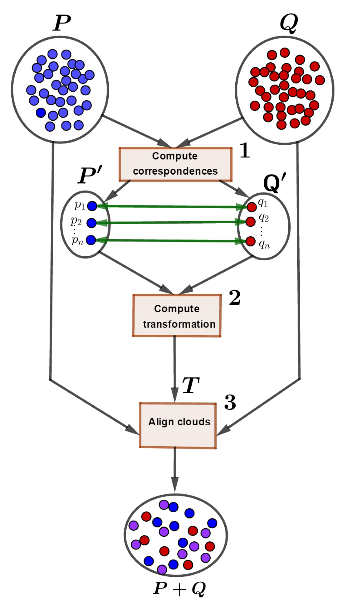
The classical approach to solve point cloud alignment problems can be summarized in three main steps, as shown in Figure 1. First, a search for correspondences between the point clouds is performed. Then, the transformation T between the set of correspondences is computed. This is followed by the alignment of the initial point sets using T. As presented in [4,5], to compute the transformations necessary for the alignment of 2 sets of points in , only 3 pairs of corresponding points from both sets are needed. To solve point cloud alignment problems, one solution is to test all possible combinations of three or more pairs of corresponding points from the 2-point clouds. However, given the large size of point clouds (several millions of points), a brute force approach that performs all possible comparisons would lead to prohibitively long computational time. Several approaches have been proposed to speed up the registration process [6]. 4PCS is one of the most recently used point cloud alignment methods because of its speed, accuracy, and capacity to handle alignments from arbitrary initial positions [3,7]. However, when the overlap ratio between the two entities to be aligned is very low (under 20%) and the overlap focuses on a relatively small area of the point clouds, 4PCS matches point clouds with misalignment [8], thus leading to a low quality of results.
We present a novel and reliable method for point cloud alignment. Our method uses efficient plane segmentation algorithms to perform point cloud alignment [9,10,11]. Our algorithm uses as inputs 2 point clouds and divides them into plane segments. From the alignment of the planes, our algorithm extracts the transformation that best aligns the initial point clouds. The algorithm is simple and does not require the initial positions of the point clouds. We performed tests on partial point clouds with low overlap. Our method shows a better alignment of the point clouds and shorter execution times compared to raw 4PCS. The alignments were performed on segments rather than on entire point clouds and are more likely to find reliable transformations that effectively align the point clouds in cases with low overlap.
2. Related Work
Point cloud registration has been performed using a variety of methods in the literature [6,9,12,13,14,15]. The effectiveness of 3D point cloud matching was demonstrated by Faugeras and Hebert [16] as part of their work on the 3D representation of objects in the early 1980s. To locate and recognize rigid objects in 3D space, they proposed a matching algorithm based on quaternions. The main drawback of their algorithm is that it requires the presence of relatively large planar regions within the point clouds. To improve this work, several other methods have been proposed, including Iterative Closest Points (ICP) introduced by Besl, et al. [4] in 1992. ICP is one of the most widely used basic approaches for point cloud registration. It is simple and easy to implement. Given two point sets P and Q in arbitrary initial positions, ICP aims to align P to Q as follows:
- Initialize registration parameters (Rotation, Translation, Scale) and registration error.
- For each point in the P, find the corresponding closest point in Q.
- Compute registration parameters, given the point correspondences obtained in step 2.
- Apply the alignment to P
- Compute the registration error between the currently aligned P and Q
- If error > threshold and max iterations has not been reached return to step 2 with new P.
ICP is reliable in ideal cases (full overlap). However, when point clouds are noisy, it requires a relatively long time for optimal rigid transform estimation, and the process has a high probability of leading to poor convergence. Several improvements and implementations have been proposed over the years to address these problems [15,17,18,19]. Yaofeng, et al. [20] suggested down-sampling the original point clouds to improve execution time. By using the kd-tree data structure, projections, and invariant feature search algorithm, several researchers have enhanced the efficiency of the matching point search step [21].
Finding correspondences is a very sensitive step for most classical point cloud registration methods [22,23,24,25]. A wrong match leads to bad results. To avoid this step, Peter and Wolfgang [26] suggested an alternative representation of point clouds: Normal Distributions Transform (NDT). They subdivided scans into cells in a 2D plane. To each cell, they assign a normal distribution, which locally models the probability of measuring a point. The result of the transform is a piece-wise continuous and differentiable probability density. Then, the matching process is done using Newton’s algorithm. Martin et al. [27] extended this work for 3D point cloud registration. As demonstrated in [27], the main drawback of this approach is the choice of cell size and the performance of the algorithm is strongly linked to the size of the cells.
Rusu et al. [28] proposed SAmple Consensus Initial Alignment (SAC-IA) for point cloud registration using a modified version of Point Feature Histograms presented in their previous work [29]. They computed the feature histogram of each point in one of the 2-point clouds to be aligned and selected a subset of points with certain pairwise distances from the second point cloud. Then, using the Point Feature Histogram, they searched for the correspondence of the selected points in the first point cloud. The main difficulty with this approach lies in the selection of the subset of points. There is no assurance that the selected points are in the overlap portion and this can lead to poor results if the overlap rate is low.
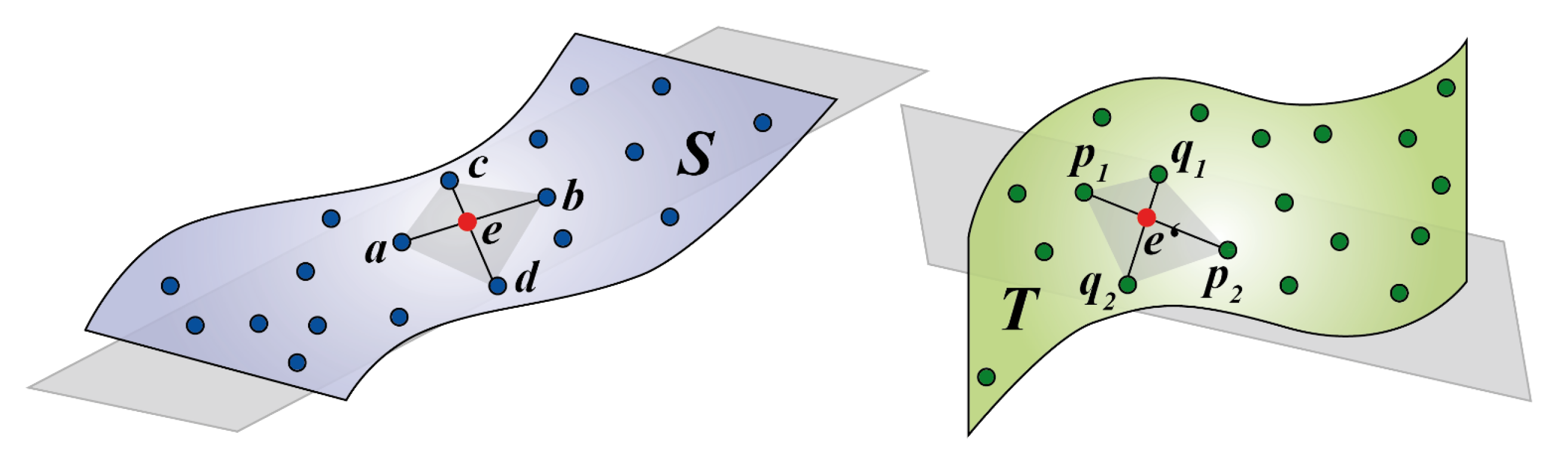
Aiger et al. [3] suggested 4-Points Congruent Sets (4PCS). 4PCS is one of the most widely used methods for point clouds alignment [6,17]. The method is purely geometric. The idea is based on the selection of four coplanar points in one of the entities, followed by a search for corresponding bases in the other entity, as shown in Figure 2. 4PCS considers point clouds alignment problems as the largest common point sets (LCP) problem [30]. The quality of the alignment is determined by the number of source points with a nearest-neighbor within a distance after the transformation. The 4PCS principle is computed with the following pseudo-code. Given two sets of points S and T in arbitrary initial positions, 4PCS aligns S and T as follows:
- Select a set of 4 coplanar points B in S
- Find the congruent bases U of B into T within an approximation level
- For each find the best rigid transform ,
- Find , such that
- If then = and
- Repeat the process from step 2 L times
- return
4PCS requires long computational time in cases where the point clouds are noisy. One of its critical steps is the search for congruence sets which may require relatively long computational time for large point clouds. To address this problem, Mellado et al. [7] proposed an improved version of 4PCS called Super4PCS (S4PCS).
3. Large Common Plansets-4PCS (LCP-4PCS)
One of the main tasks of our research is to merge several scans (partial or complete) of the same scene or object, scanned at different positions and/or with different devices. After a literature review of existing point cloud alignment methods, we opted for the 4PCS. Trial tests showed the inefficiency of the 4PCS algorithm in some cases.
- In cases where the overlap levels between the entities to be merged are very low. A relatively large increase in the number of maximum iterations sometimes leads to good results. However, the execution time increases considerably.
- In cases where overlapping portions between the point clouds to be merged are concentrated in a relatively small part of the entities. An increase in the number of iterations does not improve the results.
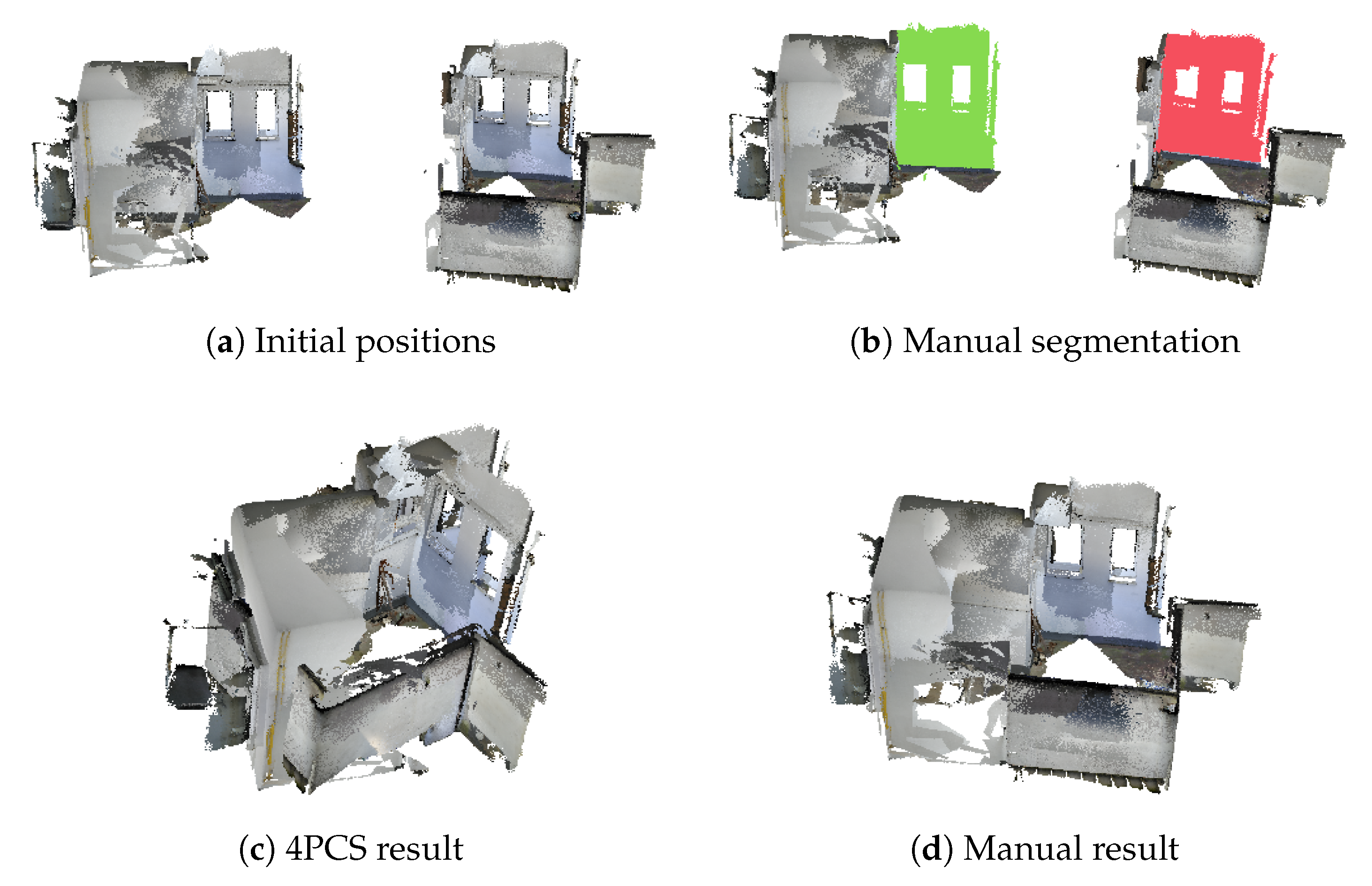
To demonstrate the inefficiency of 4PCS, an illustrative case is shown in Figure 3. Figure 3a represents two partial scans of an office room be merged. Figure 3c shows the results of the alignment of partial scans of the office room using 4PCS. A semi-automatic method where the user segments similar portions of the entities was employed to solve the mismatch in the alignment of the scans. Then, 4PCS was applied to the segmented portions of the scans. The segmented portions are highlighted in Figure 3b. An alignment of the initial entities was performed using a rigid transform from the 4PCS, see Figure 3d. This approach produces good results. However, it is influenced by the initial position of the sets to be aligned. The semi-automatic method demonstrates the existence of at least one transformation that allows for good alignments in extreme cases. This paper aims to present a method that can be used to automatically determine the best transformation without the need for user intervention.
Inspired by the principle ‘divide and rule’, the new method proceeds by segmenting point clouds. Then, the optimal rigid transform that best aligns the initial entities is estimated from the alignment of the segments using 4PCS(see Figure 4).
Unlike the 4PCS method that treats point cloud alignment problems as the largest common pointsets (LCP) problem [30], the new method treats point cloud alignment as largest common plane set problems. Thus, the method searches the rigid transform that aligns the largest number of planes.
| Algorithm 1 LCP-4PCS Given two point clouds P and Q in arbitrary initial positions, an approximation level, an overlapping threshold and a maximal iteration. |
|
Given 2 point clouds P and Q in arbitrary initial positions. Let and be the 2 segments sets obtained after segmenting P and Q respectively. Let be a function that compute the overlapping rate between the 2 segments and : with . LCP-4PCS aims to estimate such that:
where is the application of the transformation T to all the elements of .
The flowchart in Figure 4 illustrates a description of our method. is the point cloud to be aligned to the reference point cloud . Our method (LCP-4PCS) segments the point clouds (scans) according to plane structures, as shown in the flowchart. The plane structures are shown using different color shadings in the diagram. LCP-4PCS proceeds by iteratively aligning each plane of to those of using 4PCS. A plane present in both scans is shown in the flowchart (see and ). At each iteration, a transformation from 4PCS is applied to all the segments of the . After applying the transformation, correspondences between segments of and are identified based on the overlap rate of the segmented planes. At the end of the process, the transformation which aligns the largest number of planes is retained.
Model. Algorithm 1 presents the proposed model: LCP-4PCS. A parameter was introduced to make LCP-4PCS more efficient based on the realities encountered during the tests. represents the overlapping threshold from which any two segments to be aligned are considered equivalent.
Let P and Q be 2 sets of points. and are 2 segment sets obtained after segmenting P and Q respectively and . Let and :
: this function takes as input 2 sets of points , and an approximation level from which 2 points p and q are considered close and returns the matching ratio between the 2 sets. Let . According to the definition of match of the 2 sets of point above, .
: this function takes as input two sets of segments S1 and S2, a rigid transform T, an approximation level and a overlapping threshold . Let . where is the application of the transformation T to all the elements of .
Run-time. Let P and Q be two point clouds with n and m points () respectively. The segmentation step can be executed in [10]. 4PCS run in . The points sets are almost coplanar, which reduces the processing time of congruence search. The plane matching step runs in the worst case in , where and are number of planes in P and Q respectively. Our algorithm run-time is cause and . Hence in general our model runs in time and requires space.
4. Experiments and Results
We tested LCP-4PCS on a set of partial scans of several scenes with low overlap rates. Then we compared the results to those obtained with 4PCS.
4.1. Data and Implementation
We implemented our method in C++ using the point cloud manipulation functions offered by the CCLib library [17]. We used the OpenMP [31] parallelization functions to improve the performance of the algorithms.
Our tests were conducted on a set of unorganized point clouds provided by Camertronix and by our project partner Rabo. The Camertronix point clouds were partial scans of building interiors taken using a Faro Focus 3D laser scanner. The rest of our data was collected using cameras made by Rabo. The cameras have stereo systems with a set of sensors including, orientation sensors (Inertial Measurement Unit), Global Navigation Satellite System (GNSS) receivers, Laser rangefinder, and Infrared sensor (see Figure 5). They can be used to scan scenes in the range of 1–100 m with a precision of a few millimeters.
The segmentation step was executed using the method proposed by Limberger and Oliveira [10]. This method is efficient, fast, and a C++ implementation is available. However, in some cases, the method generates multiple small segments that cause a slowdown of LCP-4PCS. To prevent the generation of small segments in the segmentation step, a fusion of small segments was carried out using segment sizes and orientations [32]. A segment is considered to be small if its size is less than the average size of the segments obtained after the segmentation of a point cloud. Once identified, a small segment is added to the nearest segment. The angle between the normals of the two segments should be less than a threshold value of . During the tests, was set at . Figure 6 shows an example of the fusion process. Before executing the fusion process, 32 segments were detected from the segmentation step (see Figure 6a). Most of the segments are small. After the merging step is applied, the number of segments decreased from 32 to 9 (see Figure 6b). Table 1 shows the execution times of our algorithm with and without the merging of small segments, tested on five datasets. In some cases, the execution time is reduced by almost half. The high difference in run-time between the datasets can be explained by the differences in density of the point clouds.
4.2. Tests and Comparisons
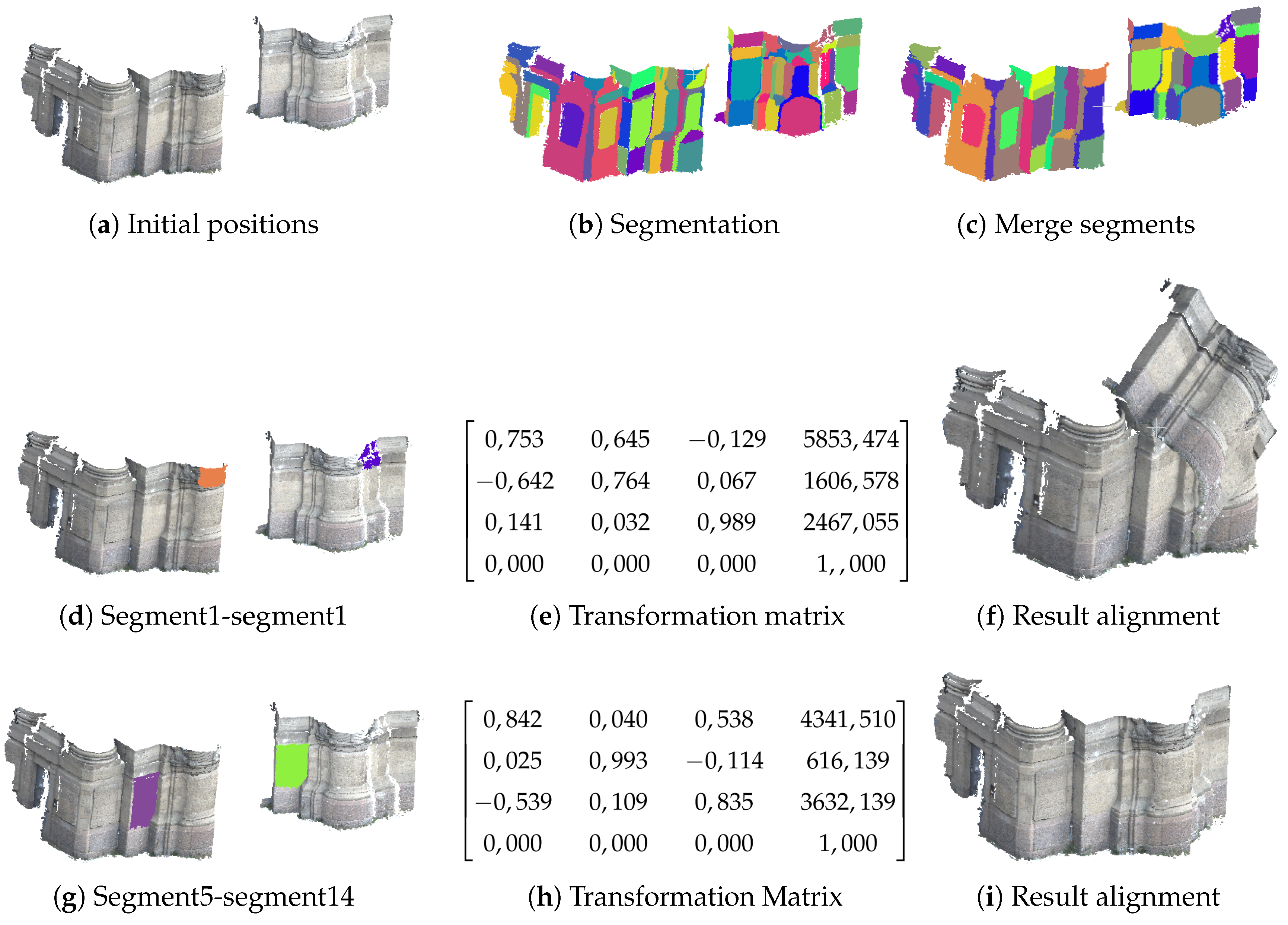
Our tests were conducted on a core i7 8th generation (1.8 GHz x 8) with 8GB RAM. Figure 7 shows some steps in the alignment of the Charlottebürgerturm dataset using LCP-4PCS. These are two partial scans of the Charlottebürgerturm monument in Berlin (Germany). After segmentation, each of the scans (Scan1 in foreground and Scan2 in background: see Figure 7a) is divided into 43 and 37 segments respectively (see Figure 7b). As shown in Figure 7c, applying the merging procedure reduces the number of segments to 25 and 22 segments. The result obtained using the transformation matrix from the alignment of segment1 of each scan matches only two segments (segment1 from Scan1 and segment1 from Scan2), as seen in the colored segments in Figure 7d. This leads to a wrong alignment of the 2 point clouds, see Figure 7f. The alignment using the transformation matrix from segment5 (Scan1) and segment14 (Scan2) produces the best result with 8 matches (see Figure 7i). At the end of the process, the transformation matrix retained is the one resulting from the alignment of segment5 (Scan1) and segment14 (Scan2).
We compared the results of LCP-4PCS to those of raw 4PCS on our datasets. The results of the alignments registered by each of the methods are rendered in the color representations in Figure 8. As can be observed, LCP-4PCS produces far better results for point cloud alignment with low overlap. This is explained by the fact that 4PCS seeks to align the largest number of points while LCP-4PCS finds the transformation matrix that aligns the highest number of segments. Table 2 illustrates the difference in the results of the two methods and demonstrates that our method can achieve good results on various datasets. The execution time of LCP-4PCS is shorter than in 4PCS. This is explained by the time required to determine the best matching points required to compute the transformation matrix, see Table 2. 4PCS searches for matching points over the entire point clouds while LCP-4PCS only focuses on the segments.
Limitation. Although our method is suitable for point cloud alignment, it was found to be very dependent on the segmentation process. Poor segmentation would lead to bad alignment quality. In addition, for datasets with overlap rates close to 100%, 4PCS may have faster execution times than LCP-4PCS. In these cases, 4PCS converges quickly while LCP-4PCS first proceeds by point cloud segmentation and then merging of the small segments.
5. Conclusions
We presented a new point cloud alignment method (LCP-4PCS) in this paper. As the name suggests, it is based on the 4PCS method. Unlike the 4PCS method that considers point cloud alignment problems as the Largest Common Pointsets (LCP) problem, LCP-4PCS treats point cloud alignment as the Largest Common plane sets problem. LCP-4PCS first segments point clouds into plane segments, then from the alignment of the segments, the geometric transformation that aligns the largest number of segments is extracted.
LCP-4PCS was proposed to solve problems encountered when aligning point clouds with a low overlap rate. Since 4PCS is based on the principle of aligning the highest number of points, the approach becomes ineffective in cases where the overlap rates are low. Hence the idea of finding the transformation that aligns the highest number of segments between point clouds.
The results of tests on our datasets show that LCP-4PCS produces results with better quality compared to 4PCS in cases with low overlap between point clouds. In addition, LCP-4PCS has a shorter execution time. We used 5 datasets to arrive at this conclusion.
The results obtained from point cloud alignment using LCP-4PCS are highly dependent on the segmentation step. Poor segmentation may cause low-quality alignment. Thus, better segmentation methods can be used according to the characteristics of the cloud points. Our future works will focus on the improvement of the segmentation step.
Author Contributions
Conceptualization, Cedrique Fotsing and Nafissetou Nziengam; Methodology, Cedrique Fotsing; Software, Cedrique Fotsing; Validation, Cedrique Fotsing, Nafissetou Nziengam and Christophe Bobda; Formal Analysis, Cedrique Fotsing; Investigation, Cedrique Fotsing and Nafissetou Nziengam; Resources, Christophe Bobda; Data Curation, Cedrique Fotsing and Nafissetou Nziengam; Writing-Original Draft Preparation, Cedrique Fotsing; Writing-Review & Editing, Cedrique Fotsing and Christophe Bobda; Visualization, Cedrique Fotsing; Supervision, Christophe Bobda; Project Administration, Christophe Bobda; Funding Acquisition, Christophe Bobda. All authors have read and agreed to the published version of the manuscript.
Funding
The research was funding by the German Federal Ministry of Science and Energy.
Acknowledgments
This work was funded as part of the ZIM (Zentrales Innovationsprogramm Mittelstand) program by the German Federal Ministry of Science and Energy under the project number 16KN068901—NeoBuild—SmartVision. SmartVision is a collaborative research project between the Technical University of Brandenburg, the Fraunhofer Heinrich-Hertz-Institute, Rabo GmbH and, Geo-Office GmbH. The authors would like to thank Camertronix SARL in Yaounde for providing the point cloud data.
Conflicts of Interest
The authors declare no conflict of interest.
References
- Bosché, F.; Forster, A.; Valero, E. 3D Surveying Technologies and Applications: Point Clouds and Beyond; Heriot-Watt University: Edinburgh, UK, 2015. [Google Scholar]
- Daneshmand, M.; Helmi, A.; Avots, E.; Noroozi, F.; Alisinanoglu, F.; Arslan, H.; Gorbova, J.; Haamer, R.; Ozcinar, C.; Anbarjafari, G. 3D Scanning: A Comprehensive Survey. Scand. J. For. Res. 2018, 30, 73–86. [Google Scholar]
- Aiger, D.; Mitra, N.J.; Cohen-Or, D. 4-Points Congruent Sets for Robust Pairwise Surface Registration. In Proceedings of the 35th International Conference on Computer Graphics and Interactive Techniques (SIGGRAPH’08) Interactive Techniques (SIGGRAPH’08), Los Angeles, CA, USA, 11–15 August 2008; Volume 27. [Google Scholar] [CrossRef] [Green Version]
- Besl, P.J.; McKay, N.D. A method for Registration of 3D Shapes. In Proceedings of the SPIE1611, Sensor Fusion IV: Control Paradigms and Data Structure, Boston, MA, USA, 12–15 November 1992; pp. 239–255. [Google Scholar]
- Horn, B. Closed-Form Solution of Absolute Orientation Using Unit Quaternions. J. Opt. Soc. A 1987, 4, 629–642. [Google Scholar] [CrossRef]
- Pomerleau, F.; Colas, F.; Siegwart, R. A Review of Point Cloud Registration Algorithms for Mobile Robotics. Found. Trends Robot. 2015, 4, 1–104. [Google Scholar] [CrossRef] [Green Version]
- Mellado, N.; Mitra, N.J.; Aiger, D. Super 4PCS: Fast Global Pointcloud Registration via Smart Indexing. Comput. Graph. Forum 2014, 33. [Google Scholar] [CrossRef] [Green Version]
- Huang, J.; Kwok, T.H.; Zhou, C. V4PCS: Volumetric 4PCS Algorithm for Global Registration. J. Mech. Des. 2017, 139. [Google Scholar] [CrossRef]
- Nguyen, A.; Le, B. 3D point cloud segmentation: A survey. In Proceedings of the 2013 6th IEEE Conference on Robotics, Automation and Mechatronics (RAM), Manila, Philippines, 12–15 November 2013; pp. 225–230. [Google Scholar] [CrossRef]
- Limberger, F.; Oliveira, M. Real-time detection of planar regions in unorganized point clouds. Pattern Recognit. 2015, 48. [Google Scholar] [CrossRef] [Green Version]
- Grilli, E.; Menna, F.; Remondino, F. A review of point clouds segmentation and classification algorithms. ISPRS Int. Arch. Photogramm. Remote Sens. Spat. Inf. Sci. 2017, XLII-2/W3, 339–344. [Google Scholar] [CrossRef] [Green Version]
- Huber, D.; Hebert, M. Fully Automatic Registration Of Multiple 3D Data Sets. Image Vis. Comput. 2003, 21, 637–650. [Google Scholar] [CrossRef] [Green Version]
- Tazir, M.L.; Gokhool, T.; Checchin, P.; Malaterre, L.; Trassoudaine, L. CICP: Cluster Iterative Closest Point for Sparse-Dense Point Cloud Registration. Robot. Auton. Syst. 2018, 108. [Google Scholar] [CrossRef] [Green Version]
- Rangaprasad, A.S.; Zevallos, N.; Vagdargi, P.; Choset, H. Registration with a small number of sparse measurements. Int. J. Robot. Res. 2019, 38, 1403–1419. [Google Scholar] [CrossRef]
- Holz, D.; Ichim, A.; Tombari, F.; Rusu, R.; Behnke, S. Registration with the Point Cloud Library—A Modular Framework for Aligning in 3-D. IEEE Robot. Autom. Mag. 2015, 22, 110–124. [Google Scholar] [CrossRef]
- Faugeras, O.; Hebert, M. The Representation, Recognition, and Locating of 3-D Objects. Int. J. Robot. Res. IJRR 1986, 5, 27–52. [Google Scholar] [CrossRef]
- CloudCompare. GPL Software. 2019. Version 2.10.3. Available online: https://cloudcompare.org/ (accessed on 28 June 2020).
- Schroeder, W.; Martin, K.; Lorensen, B. The Visualization Toolkit, 4th ed.; Kitware: Clifton Park, NY, USA, 2009; ISBN 978-1-930934-19-1. [Google Scholar]
- Rusu, R.B.; Cousins, S. 3D is here: Point Cloud Library (PCL). In Proceedings of the 2011 IEEE International Conference on Robotics and Automation, Shanghai, China, 9–13 May 2011; pp. 1–4. [Google Scholar] [CrossRef] [Green Version]
- Wu, Y.; Wang, W.; Lu, K.Q.; Wei, Y.D.; Chen, Z.C. A New Method for Registration of 3D Point Sets with Low Overlapping Ratios. Procedia CIRP 2015, 27, 202–206. [Google Scholar] [CrossRef] [Green Version]
- He, Y.; Liang, B.; Yang, J.; Li, S.; He, J. An Iterative Closest Points Algorithm for Registration of 3D Laser Scanner Point Clouds with Geometric Features. Sensors 2017, 17, 1862. [Google Scholar] [CrossRef] [PubMed] [Green Version]
- Fernández-Moral, E.; Rives, P.; Arevalo, V.; González-Jiménez, J. Scene Structure Registration for Localization and Mapping. Robot. Auton. Syst. 2015, 75. [Google Scholar] [CrossRef]
- Forstner, W.; Khoshelham, K. Efficient and Accurate Registration of Point Clouds with Plane to Plane Correspondences. In Proceedings of the IEEE International Conference on Computer Vision, Venice, Italy, 22–29 October 2017; pp. 2165–2173. [Google Scholar] [CrossRef]
- Li, X.; Guskov, I. Multiscale Features for Approximate Alignment of Point-based Surfaces. In Proceedings of the Symposium on Geometry Processing, Vienna, Austria, 4–6 July 2005; pp. 217–226. [Google Scholar]
- Gelfand, N.; Mitra, N.; Guibas, L.; Pottmann, H. Robust Global Registration. In Proceedings of the Symposium on Geometry Processing, Vienna, Austria, 4–6 July 2005. [Google Scholar]
- Biber, P.; Straßer, W. The Normal Distributions Transform: A New Approach to Laser Scan Matching. In Proceedings of the 2003 IEEE/RSJ International Conference on Intelligent Robots and Systems (IROS 2003)(Cat. No. 03CH37453), Las Vegas, NV, USA, 27–31 October 2003; Volume 3, pp. 2743–2748. [Google Scholar] [CrossRef]
- Magnusson, M.; Lilienthal, A.; Duckett, T. Scan Registration for Autonomous Mining Vehicles Using 3D-NDT. J. Field Robot. 2007, 24, 803–827. [Google Scholar] [CrossRef] [Green Version]
- Rusu, R.; Blodow, N.; Beetz, M. Fast Point Feature Histograms (FPFH) for 3D registration. In Proceedings of the 2009 IEEE International Conference on Robotics and Automation, Kobe, Japan, 12–17 May 2009; pp. 3212–3217. [Google Scholar] [CrossRef]
- Rusu, R.; Blodow, N.; Marton, Z.; Beetz, M. Aligning Point Cloud Views using Persistent Feature Histograms. In Proceedings of the 2008 IEEE/RSJ International Conference on Intelligent Robots and Systems, Nice, France, 22–26 September 2008; pp. 3384–3391. [Google Scholar] [CrossRef]
- Ambühl, C.; Chakraborty, S.; Gärtner, B. Computing Largest Common Point Sets under Approximate Congruence. In European Symposium on Algorithms; Springer: Berlin/Heidelberg, Germany, 2000; Volume 1879, pp. 52–63. [Google Scholar] [CrossRef]
- Dagum, L.; Menon, R. OpenMP: An Industry-Standard API for Shared-Memory Programming. Comput. Sci. Eng. IEEE 1998, 5, 46–55. [Google Scholar] [CrossRef] [Green Version]
- Balado Frias, J.; Díaz Vilariño, L.; Arias, P.; Gonzalez, H. Automatic classification of urban ground elements from mobile laser scanning data. Autom. Constr. 2018, 86, 226–239. [Google Scholar] [CrossRef] [Green Version]
Figure 1.
General approach to point cloud registration: let P and Q be two sets of overlapping points in two different spaces. P and Q are aligned in the same space using the following steps: 1—find two sets of corresponding points and in P and Q respectively; 2—compute the transformation T such that ; 3—use T to align P and Q (apply ).

Figure 2.
Affine invariant ratio for congruent 4-points. Given points from a surface S, let points be coplanar, and the lines and meet at point e. The ratios and are preserved under any affine transform. If T is another surface which (partially) matches S and the 4-points coplanar base lies in the overlap region, then the set of corresponding points from T are coplanar, and satisfy the following relations: and .

Figure 3.
Assisted approach by user’s graphical segmentation: (a) Point clouds initial positions; (b) Segmented portions (by the user); (c) Result using 4PCS (100 iterations) without user segmentation; (d) Result using rigid transform from 4PCS (20 iterations) perform on segmented portions.
Figure 3.
Assisted approach by user’s graphical segmentation: (a) Point clouds initial positions; (b) Segmented portions (by the user); (c) Result using 4PCS (100 iterations) without user segmentation; (d) Result using rigid transform from 4PCS (20 iterations) perform on segmented portions.

Figure 4.
LCP-4PCS: let two point clouds and be two partial or complete overlapping scans of the same object. To align to , LCP-4PCS proceeds as follows: segments and into planes; applies iteratively 4PCS to individually align segments to segments; at each iteration, uses the transformation from 4PCS process to find a set corresponding segments by applying to segments; finally uses the transformation T from the previous step which builds the largest set of corresponding planes between segments and segments to align and (applies ).
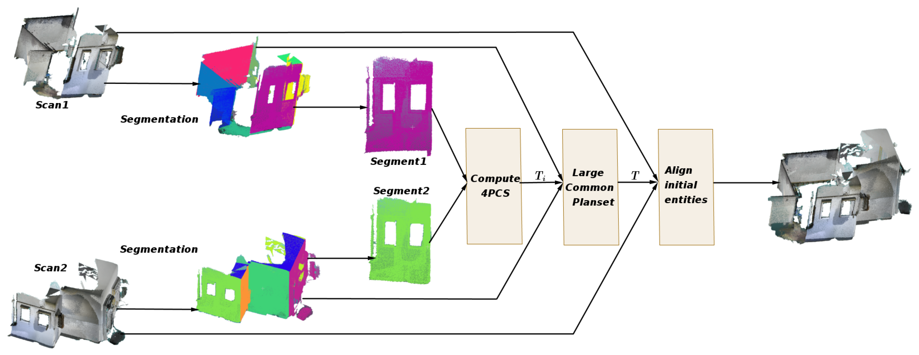
Figure 5.
Point clouds acquisition: (a) Stereo cameras system, (b) Camera in action on the field during the scan of the data set “Charlottebürgerturm” in Berlin (Germany).
Figure 5.
Point clouds acquisition: (a) Stereo cameras system, (b) Camera in action on the field during the scan of the data set “Charlottebürgerturm” in Berlin (Germany).
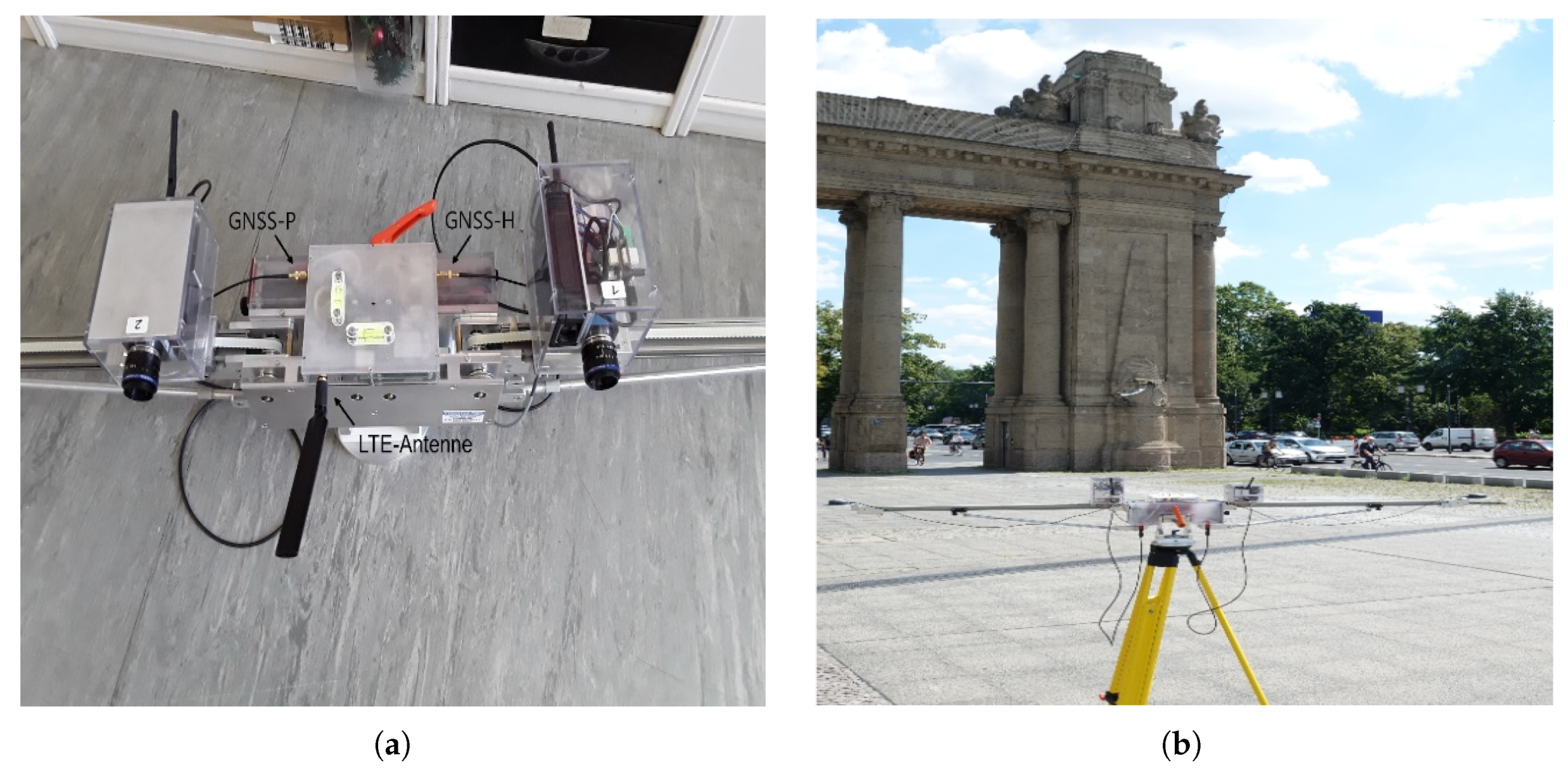
Figure 6.
Example of small planes fusion after segmentation.
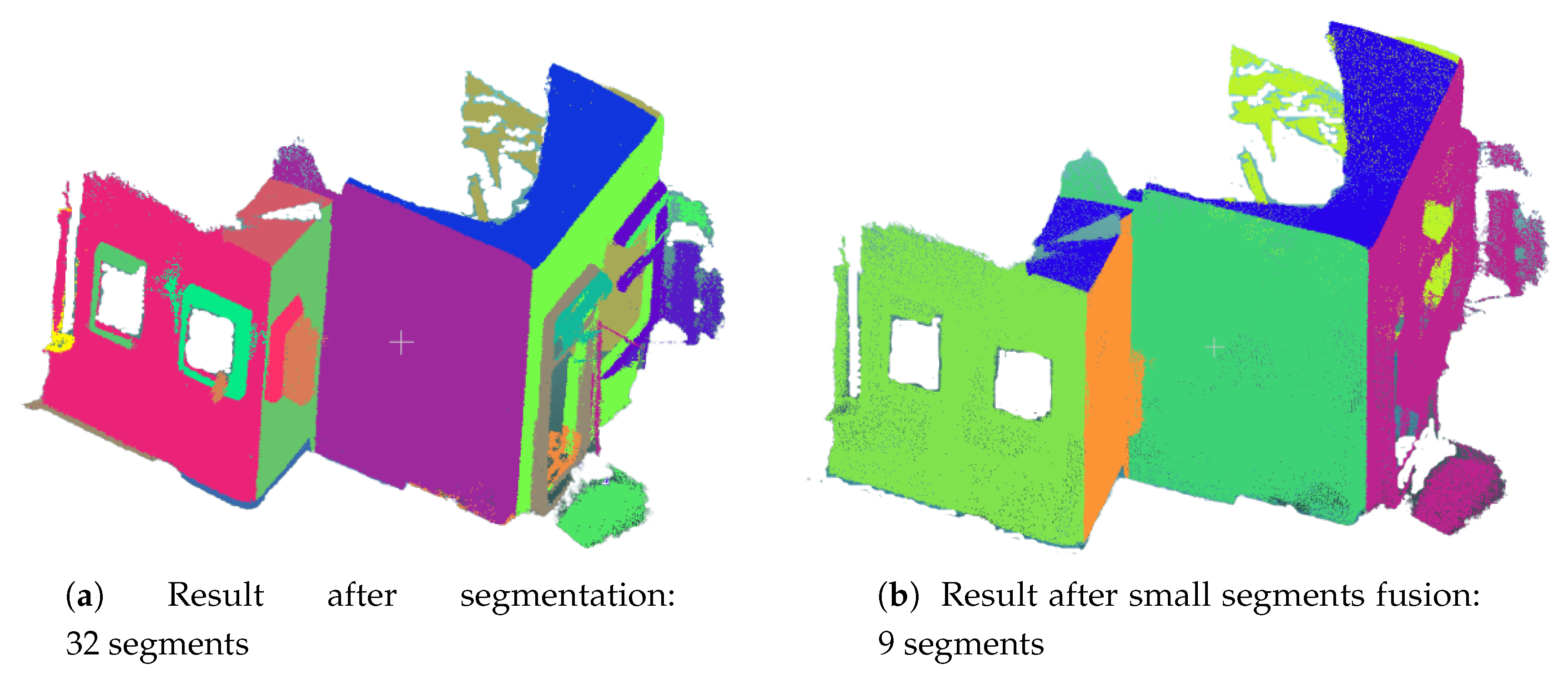
Figure 7.
Some steps of the alignment of “CharlotteBürgerturm” dataset with LCP-4PCS: (a) Initial position of the scans, (b) Result of segmentation Scan1(foreground) 43 segments and Scan2(background) 37 segments, (c) Merging result Scan1(25 segments) and Scan2(22 segments), (d) Representation of the first segments of the scans, (e) Transformation matrix from the alignment of the first segments, (f) Alignment result using the matrix in “e” (number of matched segment: 1), (g) Representation segment8(Scan1) and segment13(Scan2), (h) Transformation matrix from the alignment of segment5 and segment14, (i) Alignment result using the matrix in “h”(number of matched segments: 8).

Figure 8.
Result of point cloud alignments on Camertronix dataset, CharlotteBürgerturm dataset, Valentino dataset and, Buro dataset from top to bottom, respectively. First column: initial position of the point clouds; Second column: the results of the alignments with 4PCS, third column: the results of the alignments using LCP-4PCS


Table 1.
LCP-4PCS execution time before and after merging small segments.
| Dataset | Scan1 | Scan2 | Time(s) | |||
|---|---|---|---|---|---|---|
| Number Segments before Fusion | Number Segments after Fusion | Number Segments before Fusion | Number Segments after Fusion | Time before Fusion | Time after Fusion | |
| Camertronix | 27 | 14 | 11 | 8 | 179 | 107 |
| Valentino | 34 | 21 | 19 | 14 | 75 | 44 |
| Charlottebügerturm | 43 | 25 | 37 | 22 | 162 | 91 |
| Buro | 32 | 9 | 11 | 6 | 173 | 98 |
| Flurzimmer | 27 | 18 | 6 | 5 | 74 | 49 |
Table 2.
Performances of 4PCS and LCP-4PCS on our datasets.
| Dataset | Size(x1000) | 4PCS | LCP-4PCS | ||||
|---|---|---|---|---|---|---|---|
| Scan1 | Scan2 | Aligned Samples (%) | Time (s) | Aligned Samples (%) | Number Aligned Segments | Time (s) | |
| Camertronix | 1,708,126 | 1,281,042 | 528 | 141 | 17.2 | 3 | 107 |
| Valentino | 82,259 | 75,533 | 507 | 108 | 223 | 2 | 44 |
| Charlottebürgerturm | 1,218,731 | 1,132,942 | 998 | 165 | 208 | 8 | 91 |
| Buro | 1,447,277 | 1,051,268 | 673 | 125 | 191 | 2 | 98 |
| Flurzimmer | 95,804 | 89,378 | 494 | 93 | 157 | 2 | 49 |
Publisher’s Note: MDPI stays neutral with regard to jurisdictional claims in published maps and institutional affiliations. |
© 2020 by the authors. Licensee MDPI, Basel, Switzerland. This article is an open access article distributed under the terms and conditions of the Creative Commons Attribution (CC BY) license (http://creativecommons.org/licenses/by/4.0/).
Share and Cite
MDPI and ACS Style
Fotsing, C.; Nziengam, N.; Bobda, C. Large Common Plansets-4-Points Congruent Sets for Point Cloud Registration. ISPRS Int. J. Geo-Inf. 2020, 9, 647. https://0-doi-org.brum.beds.ac.uk/10.3390/ijgi9110647
AMA Style
Fotsing C, Nziengam N, Bobda C. Large Common Plansets-4-Points Congruent Sets for Point Cloud Registration. ISPRS International Journal of Geo-Information. 2020; 9(11):647. https://0-doi-org.brum.beds.ac.uk/10.3390/ijgi9110647
Chicago/Turabian StyleFotsing, Cedrique, Nafissetou Nziengam, and Christophe Bobda. 2020. "Large Common Plansets-4-Points Congruent Sets for Point Cloud Registration" ISPRS International Journal of Geo-Information 9, no. 11: 647. https://0-doi-org.brum.beds.ac.uk/10.3390/ijgi9110647
Note that from the first issue of 2016, this journal uses article numbers instead of page numbers. See further details here.