Article

A BIM Based Hybrid 3D Indoor Map Model for Indoor Positioning and Navigation

1
School of Geomatics and Urban Spatial Information, Beijing University of Civil Engineering and Architecture, No. 1 Zhan Lan Guan Path, Xicheng District, Beijing 100044, China
2
Key Laboratory for Urban Geomatics of National Administration of Surveying, Mapping and Geoinformation, Beijing 100044, China
*
Author to whom correspondence should be addressed.
ISPRS Int. J. Geo-Inf. 2020, 9(12), 747; https://0-doi-org.brum.beds.ac.uk/10.3390/ijgi9120747
Submission received: 27 October 2020 / Revised: 7 December 2020 / Accepted: 10 December 2020 / Published: 13 December 2020

Abstract

:
Accurate and fast indoor Location-Based Services (LBS) is very important for daily life and emergency response. Indoor map is the basis of indoor LBS. The model construction and data organization of indoor map are the key scientific problems that urgently need to be solved in the current indoor LBS application. In recent years, hybrid models have been used widely in the research of indoor map, because they can balance the limitations of single models. However, the current studies about hybrid model pay more attention to the model accuracy and modeling algorithm, while ignoring its relationship between positioning and navigation and its practicality in mobile indoor LBS applications. This paper addresses a new indoor map model, named Building Information Modeling based Positioning and Navigation (BIMPN), which is based on the entity model and the network model. The highlight of BIMPN is that it proposes a concept of Step Node (SN) to assist indoor positioning and navigation function. We developed the Mobile Indoor Positioning and Navigation System (MIPNS) to verify the practicability of BIMPN. Results indicate that the BIMPN can effectively organize the characteristics of indoor spaces and the building features, and assist indoor positioning and navigation. The BIMPN proposed in this paper can be used for the construction of indoor maps and it is suitable for mobile indoor positioning and navigation systems.

Graphical Abstract

1. Introduction

With the rise of mobile Internet and the wide application of location services, people’s need for navigation has increased, especially when they are in an unfamiliar and complex indoor environment, such as the library [1], shopping malls [2], and hospital [3]. In addition, with the diversification of indoor applications, the application value of indoor location-based service (LBS) in indoor application has gradually become prominent, including indoor emergency rescue [4], indoor facility management [5], indoor personnel positioning and tracking [6]. As a well-known type of indoor space expression, indoor map model is an essential part of indoor LBS [7]. The markers and context information in indoor map can be used to correct indoor positioning errors and plan indoor navigation paths [8,9]. However, the existing indoor map technology is still in a relatively immature state. It has some problems such as a single model application scenario and incomplete coverage of element information, so it cannot adapt to the challenges of complex building indoor environments and diversified indoor applications. Moreover, in the design and construction of the existing indoor map model, the coordination between the indoor map and the indoor LBS is often neglected. As a result, the indoor map cannot be maximally used in the indoor LBS.
At present, many scholars have conducted research on the above challenge and various models have been proposed to construct the indoor map for indoor navigation, including network model, grid model, and entity model [10,11,12]. (1) The network model abstracts indoor space as nodes and the topological relationship between indoor spaces as edges to form a node-relation graph. In 2000, Lee first proposed a Combined Data Model (CDM) based on the dual theory of Poincare. However, due to the lack of the description of geometric information in CDM, it is not applicable in navigation. Therefore, building on CDM, Lee further put forward the Geometric Network Model (GNM) by means of Medial Axis Transformation (MAT) [13], and applied it to indoor path planning. The GNM, including geometric and topological information, has been extensively recognized and implemented in indoor navigation [14]. In the IndoorGML standard proposed by OGC, the geometric network model is also used to describe the indoor topology and build the indoor path network [15]. In addition, Yuan et al. [16] optimized the geometric network model by adding visual nodes, and developed an indoor space model of “door-door”. Liu and Goetz et al. [17,18] also adopted this abstract method to obtain the interior space model. (2) The grid model divides the indoor space into grids in a specific way. The size of the grid determines the fineness of the indoor spatial information expression, but with more grids, more computer memory is required, and the efficiency is lower. According to the size and shape of the grid, it can be divided into Regular Grid Models (RGM) and Irregular Grid Models (IGM) [19]. The voxel model is the extension of RGMs in 3D, which exists in a 3D, regular, and rectangular array of cells (the voxels) [20]. RGMs decompose indoor space into figures with the same shape, such as rectangle, hexagon, and octagon. W. Wang et al. [21] divided the interior space into regular hexagonal grids and applied them to plan path in indoor navigation. IGMs divide the indoor space into irregular polygons, including irregular triangles, Voronoi polygons, and so on [11]. M. Xu et al. [22] took building information modeling (BIM) as the basic data and applied the spatial subdivision method based on irregular triangles to build the indoor navigation model considering obstacles. (3) The entity model utilizes the entity with geometric information to express indoor space. It has a good visualization effect and can be transformed into a network model or a grid model in a certain way [11]. In current research, entity models are usually generated from a two-dimensional (2D) floor plan or constructed from a 3D modeling software [23,24]. There are two main forms of entity model. One is the geometric boundary entity model that expresses the indoor space cell by volume shape. Its construction depends on the acquisition of indoor space boundary. Zhou et al. [11] extracted the space boundary with the isolated components of the closed space, and the interior space information model was constructed based on the interior space boundary calculation. The other is the 3D building entity model composed of 3D building components [23]. Unlike the former that focuses on indoor space cells (room, corridors, etc.), the latter pays more attention to indoor building components (walls, doors, windows, etc.). Network and grid models are often used to calculate navigation path for their good representation of spatial connectivity. The former has good visibility but poor flexibility. The latter is weak in visibility but has better flexibility, and it is usually used to plan the path with obstacles. However, as abstract representations of indoor space, they are mostly expressed in 2D and cannot simulate the real situation in the 3D interior space. As a 3D model, the entity model has more advantages in the representation of indoor 3D space. However, due to its weak ability of capturing spatial relationship, it is unable to directly carry out path planning.
In order to compensate the limitation of a single model, scholars have proposed various hybrid models to improve performance [10]. Approaches for building hybrid models can be divided into two categories from two different perspectives. The first category is a hybrid of single models built by adopting different indoor space modeling methods. For example, Lin et al. [10] put forward an indoor space hybrid model based on topology and grid. It divides indoor space into different topological subspace and grid subspace and establishes an association between them. Yang and Worboys [25] proposed a formal model, based on combinatorial graphs, which is used to automatically compute navigation graphs for indoor space. Becker et al. [26] came up with a Multi-Layered Space Model (MLSM) based on the framework of structured spatial model, which divides indoor space into the original space and the dual space, and uses different models to express it. The MLSM provides a new concept for the mixed form of spatial model. The second category is a hybrid of different models based on the building field and the geospatial field [27]. Different from the outdoor space, the indoor space is located in the architectural environment rather than the natural environment. Therefore, there are different descriptions of indoor space models in cartography/GIS (Geographic Information System/Science) and AEC (architecture, engineering, and construction) [28,29,30]. BIM is the most frequently discussed model in the AEC industry [30,31]. Obviously, BIM contains a large amount of geometric and semantic indoor information for a building, which is the basis for building indoor models [32,33]. Meanwhile, the most prominent standard for indoor models discussed throughout the GIS domain is OGC CityGML and IndoorGML [30,33]. The most interesting thing about CityGML is that it defines five different “levels of detail (LODs)”, which are used to describe a building. IndoorGML is a model for indoor positioning and navigation proposed by OGC, but it can only be applied as an auxiliary model because it does not have complete geometric information. It can be seen that the indoor building map model belong to the intersection of GIS and AEC. Therefore, the combination of BIM and GIS has been the main trend in recent years to solve the problem of indoor map modeling [32,34]. For example, Isikdag et al. [35] developed a new model, namely BIM Oriented Indoor Data Model (BO-IDM) that transforms 3D geometry and material information in BIM/IFC model to be compatible with the ESRI ArcGIS system. The Unified Building Model (UBM), which integrates IFC and CityGML, introduced by Mekawy et al. [36], is an intermediate model implemented in ArcGIS.
There is no doubt that the hybrid model, which contains more indoor space information, promotes the development of indoor map model and its application in indoor LBS. Nonetheless, currently there is not an effective hybrid indoor map model for mobile indoor positioning navigation applications, because the current hybrid model focuses more on model accuracy and modeling algorithms and ignores the relationship between map and positioning navigation. Based on the above analysis and technical investigations, this paper presents a 3D indoor hybrid building map model, named Building Information Modeling based Positioning and Navigation (BIMPN) for mobile indoor navigation systems. The highlight of BIMPN is that it proposes a concept of Step Node (SN) to assist indoor positioning and navigation function, including map matching and estimation of path distance and time. Meanwhile, it considers the visualization of map models and the habits of users using outdoor map [7,37], which has some effects on the application of BIMPN in mobile indoor navigation systems. Since the current outdoor map basically uses the 2D road network model, compared with grid model, network model has better advantages in indoor and outdoor connections, and it is also in line with the current habits of people using maps. In addition, because this study is oriented to mobile application development and the computational efficiency of the grid model has higher hardware requirements, the network model is more conducive to use in mobile applications. So, this study chooses to build BIMPN by using the network model and the entity model and discusses it in depth from the perspective of model data reorganization and model connection. In summary, the starting point of this research is to propose a hybrid indoor map model suitable for mobile indoor positioning and navigation, and hope to solve the problem that the current indoor map hybrid model cannot be maximally used in indoor positioning and navigation.
The organization of this paper is as follows. Section 2 describes the construction method of hybrid model and its application in indoor positioning and navigation in detail. Section 3 presents the experiment and results. Section 4 discusses the usability and advantage. Finally, Section 5 concludes this study.

2. Method

In this section, the specific construction method of BIMPN is further described. The process is shown in Figure 1. Firstly, the effective information is extracted from BIM to reorganize entity and network models respectively. The entity model section is represented by 3D building component elements and it is mainly used for building information provision and visualization (detail in Section 2.1). The network model section is abstracted by spatial elements and their topological relationships and it is used to aid path planning in navigation as well as map matching of positioning results (detail in Section 2.2). Next, these two models are organically connected through the direct connection and indirect connection between elements in different model (detail in Section 2.3). Finally, the hybrid map model is established. It is worth mentioning that in BIMPN, a concept of SN, is proposed to assist the positioning and navigation function. This is further described in detail in Section 2.4. Table 1 shows the main features in the hybrid model. The entity model and the network model respectively include entity elements, nodes and edge elements. These elements are further divided into different features according to their respective directions and functional attributes. Table 1 expresses the different granularity of the hybrid model from model to element to feature.

2.1. Entity Model Part of BIMPN

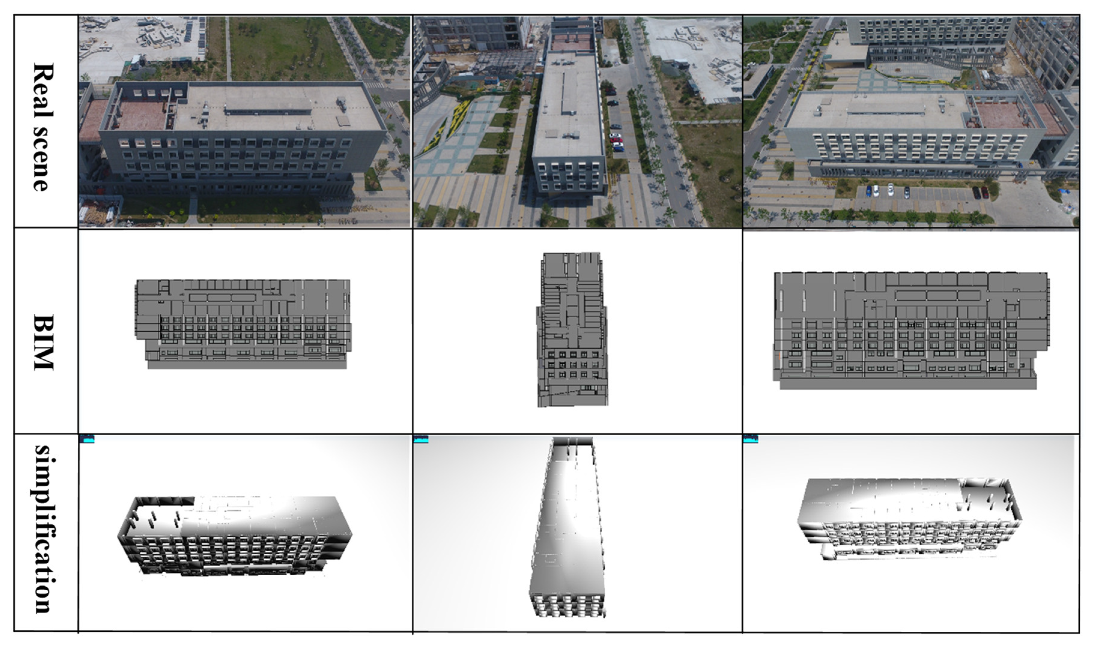
The entity model can improve the visualization effect of indoor LBS applications and provide a better visual experience for users, while also being an important material source of Indoor 3D Network Model. As described in the introduction, there are two main types of current entity models, the geometric boundary model and the 3D building model. As shown in Figure 2, the former (a) expresses the indoor space cell by volumetric shapes, and the latter (b) is mainly composed of 3D building components. Compared with the geometric boundary model, the 3D building model is closer to the real indoor environment, which is conducive to the simulation of the real scene. In this way, when users navigate in a new building environment, they can familiarize themselves with it, which is very important for indoor navigation. Therefore, 3D building component elements (specific objects) are selected as the main form of the presentation of the entity model in BIMPN. The necessarily required building component elements are shown in Table 1. The horizontal and vertical directions respectively include: wall, column, door windows, floor, facilities and stair, elevator.
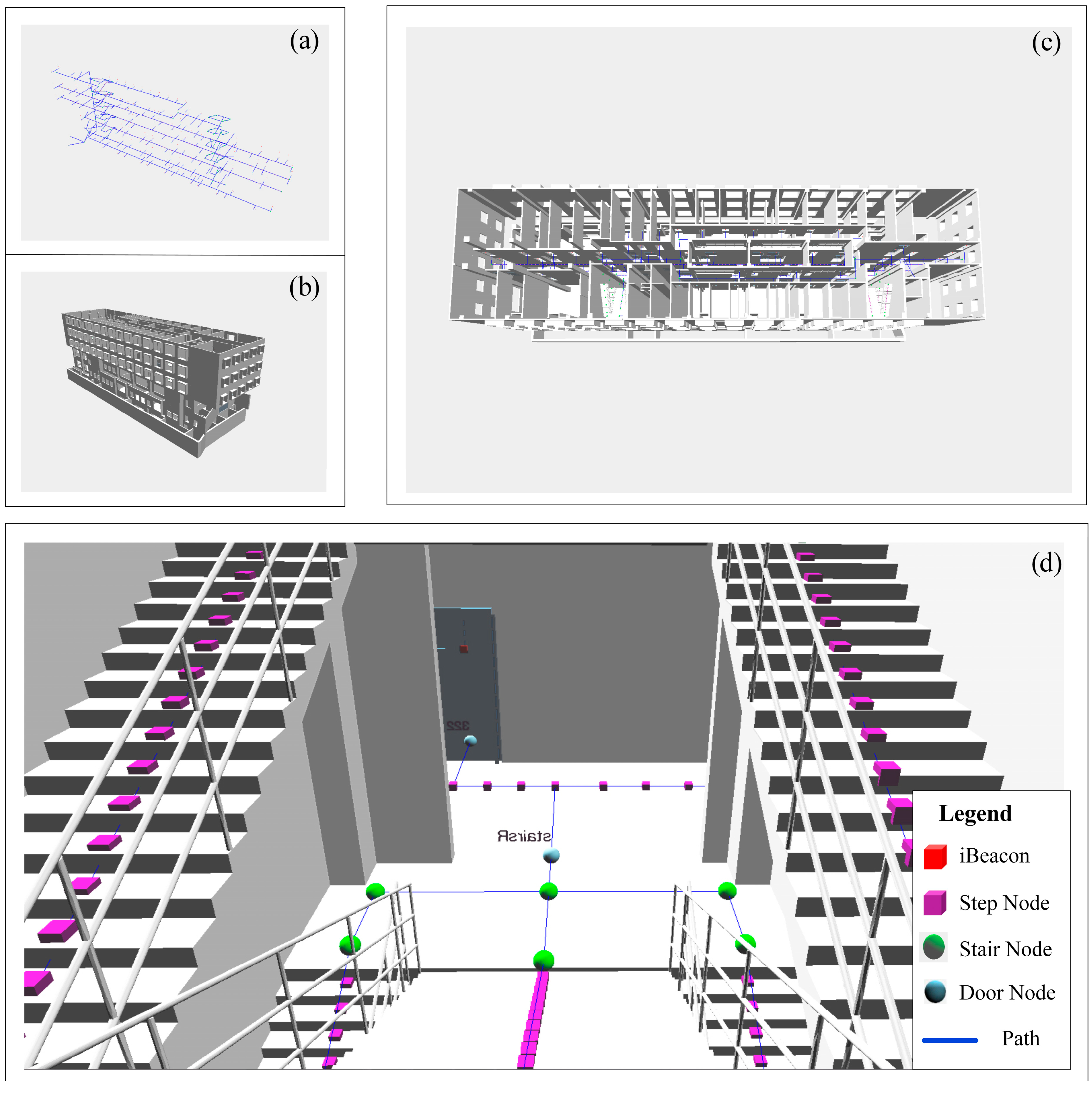
However, the 3D building model also has its limitations in space concept, especially the identification of rooms. Therefore, when using 3D building component elements to build an entity model, it is necessary to consider the expression of the space concept. In the actual indoor environment, space is usually surrounded by 3D building elements [28]. Therefore, as shown in Figure 2c, with reference to the spatial representation in the geometric boundary model, the space is expressed indirectly through the building component elements that have a boundary relationship with the room. In other words, in the entity model of BIMPN, the space is not directly expressed while indirectly expressed by the topological relationships with the surrounding building component elements. In this way, the space constructs the relevance with building component elements surrounding itself so that it can be queried in the spatial query operation of GIS as the object. After constructing the entity model, we need to complete another part of the BIMPN content that builds network models.

2.2. Network Model Part of BIMPN

The indoor 3D path network model is a further abstract expression of the indoor spatial relationship based on the entity model. In addition to the display of navigation paths, it also plays a significant role in the calculation of path planning. An ideal indoor path network model should be able to express the geometric and semantic information required for indoor navigation in detail, and the topological relationship between the objects inside the building. In BIMPN, the indoor 3D path model is described as a network model based on the relationship structure of nodes. In this model, nodes are applied to describe a space while edges represent the relationship between spaces. It is composed of multiple horizontal single-layer network models through different traffic modes in the vertical direction. Therefore, the construction of the path network model in BIMPN needs to consider two aspects: One is the organization of the horizontal single-layer path network model, and another one is the model expression of different traffic modes in the vertical direction.

2.2.1. Construction of the Network Model in the Horizontal Direction

In the construction of the horizontal single-layer path network model, node selection based on spatial abstract expression is important. In the outdoor map navigation tool, start point and end point of user (the location of the target) are taken as nodes, and the paths connecting these two types of nodes as edges. As shown in Figure 3, the node elements in the network model include: room node, door node, window node and facilities node. Considering the user’s habits, these nodes are further divided into target nodes and connectivity nodes. As shown in Table 1, target nodes include room nodes and facility nodes, which are often represented as the end point or starting point of the path in the interior space. Room is an indoor unit space with a specific functional description. It is the most common type of indoor space as a navigation destination. For example, in a large market, people usually choose shops (rooms) they need as their destination. There are two situations for room identification (ID). One is the name of the room and another is the house number. The former is applied when the function of each room in a building is different. For example, different shops in a shopping mall have different names. The latter occurs in places where the functions of rooms in buildings are similar, such as apartments. When dealing with emergency navigation, indoor facilities such as fire hydrants are the target for relevant rescuers [3]. Therefore, these indoor facilities that may be used as targets in specific scenarios can be generalized as the second category.
The setting of connectivity nodes is to express the connectivity between spaces, and its availability is related to whether the path can pass. As shown in Table 1, there are two kinds of connectivity nodes in the horizontal direction, door nodes, and window nodes. The door nodes include stair door nodes and elevator door nodes that are used to connect the vertical path. The window nodes are not used in normal navigation except for emergencies. Besides, in order to ensure connectivity between each floor space, connectivity nodes are also added in the vertical direction, which is described in detail in Section 2.2.2.
Edge is another important element besides nodes. The horizontally oriented edge consists of two parts: the corridor and the relation. Corridor is a special space, and its function is different from other horizontal room. As one of the main ways of spatial connection in the horizontal direction, it is more appropriate to abstract corridors as centerline [19] than a point. The corridor is reflected as traffic routes in the navigation network by the centerline method reasonably. The relations in horizontal are described in three types: corridor-door-room, room-door-room, and corridor-component. As shown in Figure 3, the relationship between doors and corridor or between components and corridor is plotted based on the vertical line. The room is connected with other spaces by the door and the relationship between them is plotted based on two-point connection.

2.2.2. Construction of Network Model in Vertical Direction

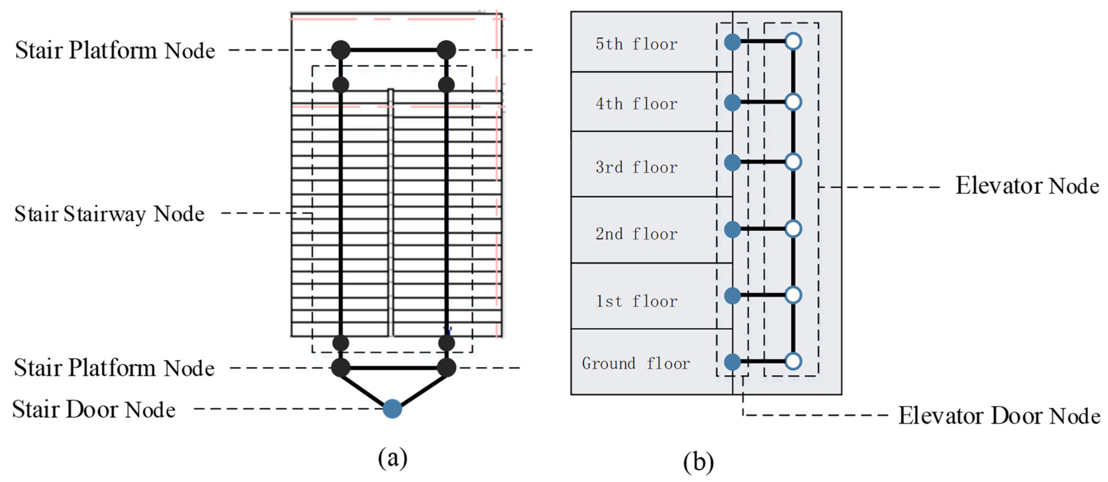
Unlike outdoor space, indoor space considers not only the horizontal path network but also the vertical path network which is built differently depending on the mode of transportation. The stair is the most common indoor vertical transportation method which consists of stair platform and stair stairway. As shown in Figure 4a, the stair stairway node is set up at the starting and the terminal of the stair stairway and two stair platform nodes are arranged on the central axis of the stair platform, and then these nodes are connected in turn to form a complete stair path. The elevator is another common indoor vertical transportation method, and its modeling is simpler than stairs. As shown in Figure 4b, the elevator of each floor is abstracted as a virtual node and then the elevator nodes of the adjacent layer are connected to form vertical connection. Finally, the stair platform nodes and the elevator node of each floor are connected to the staircase door node and elevator door node of the floor, respectively.

2.3. Model Connection of Entity Model and Network Model

BIMPN is a hybrid model that consists of the network model and the entity model. This section focuses on the model connection between these two models, which is essential for hybrid model and its applications. The model connection in BIMPN is the interaction between these two models in the hybrid model, rather than a simple combination in which they work separately. For example, when querying room A, in addition to the node element of room A in the network model, building component elements such as walls and doors that have topological relationships with room A in the entity model are able to be queried simultaneously.
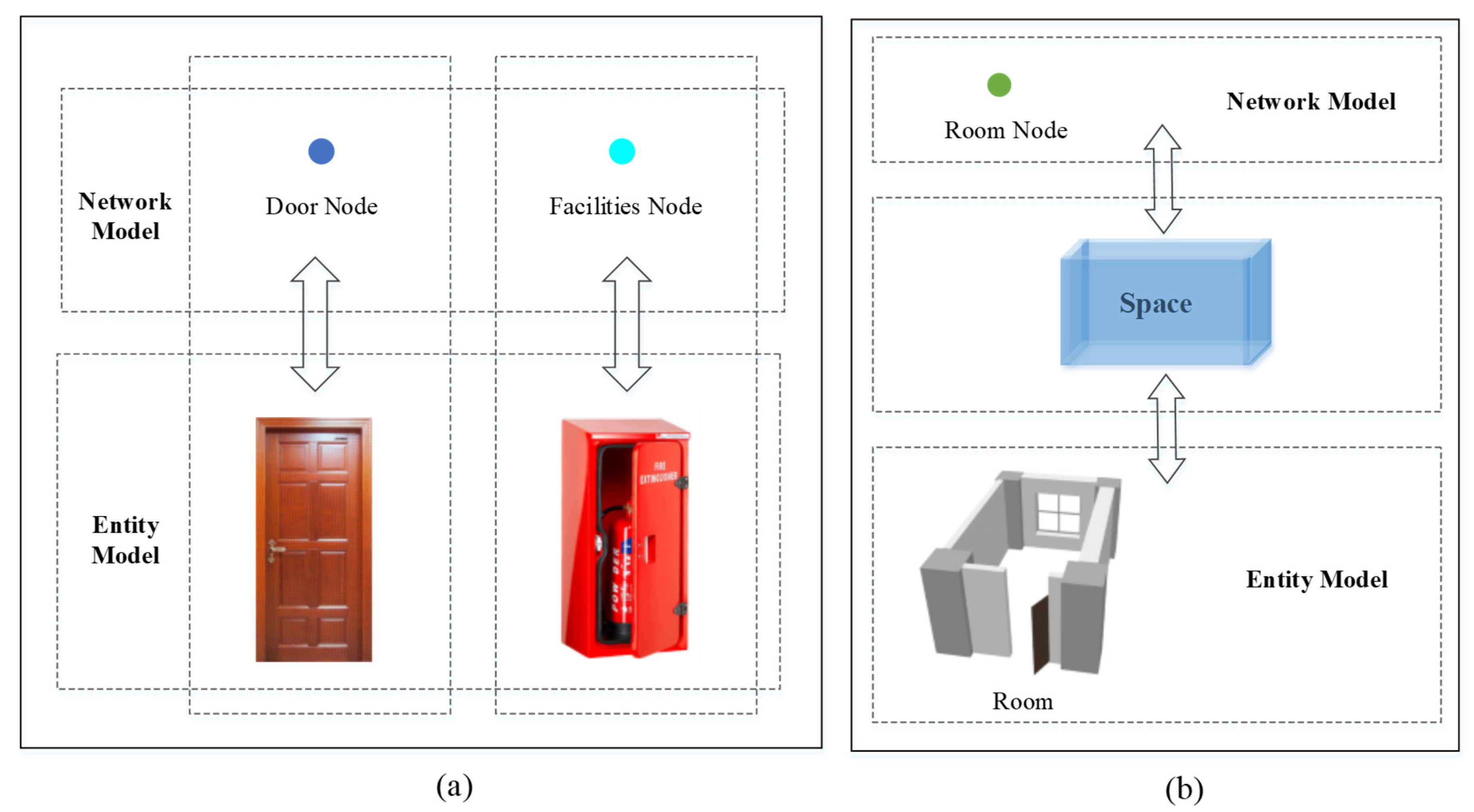
The model connection between the network model and the entity model depends on the semantic relationship between the elements in different models. There are two kinds of relationships between elements in different models: one is direct relationships, and the other is indirect relationships. As shown in Figure 5a, direct relationships exist in connectivity nodes and facilities nodes in the network model, which have a one-to-one relationship with the building component elements in the entity model. For example, the relationship between the door node in the network model and the door component in the entity model is direct. Indirect relationships are mainly due to the different expression of the room between the network model and the entity model. In the network model, the room is abstracted as room node; while in the entity model, the room is composed of multiple building component elements. Therefore, indirect relations exist in room. The specific description is shown in Figure 5b: The relationship between room and the elements in the network model and the relationship between room and the elements in the entity model are established respectively. Afterwards, indirect relationships between the network model and the entity model are established by taking room as the medium.
In the network model, because the room is the direct abstract expression, the relationship between elements and the room is one-to-one. In the entity model, the relationship between elements and the room can be divided into three categories:
  • Containment relationship means that the room contains building component elements, such as the column located in the room.
  • Boundary relationship means that the building component elements at the boundary of the room, such as doors or walls located on the boundary of the room.
  • Other features in the building map, such as corridor, stair, etc. are similar to this situation.

2.4. BIMPN Assistance in Indoor Positioning and Navigation

For indoor navigation, the indoor map model not only is the visual carrier of indoor path and positioning results but also plays an auxiliary role in map matching for indoor positioning and path planning for indoor navigation. Therefore, apart from data organization and information expression, it is also necessary for indoor map model that consider how to better assist indoor positioning and navigation. In BIMPN, the concept of Step Node (SN) is proposed based on the network model and the user’s step distance, which is further divided into the step-anchor node and the step-end node. The main functions of SN are (1) map matching between indoor positioning results and network models and (2) as an edge-weight reference value to assist path planning.

2.4.1. Setting Step Node

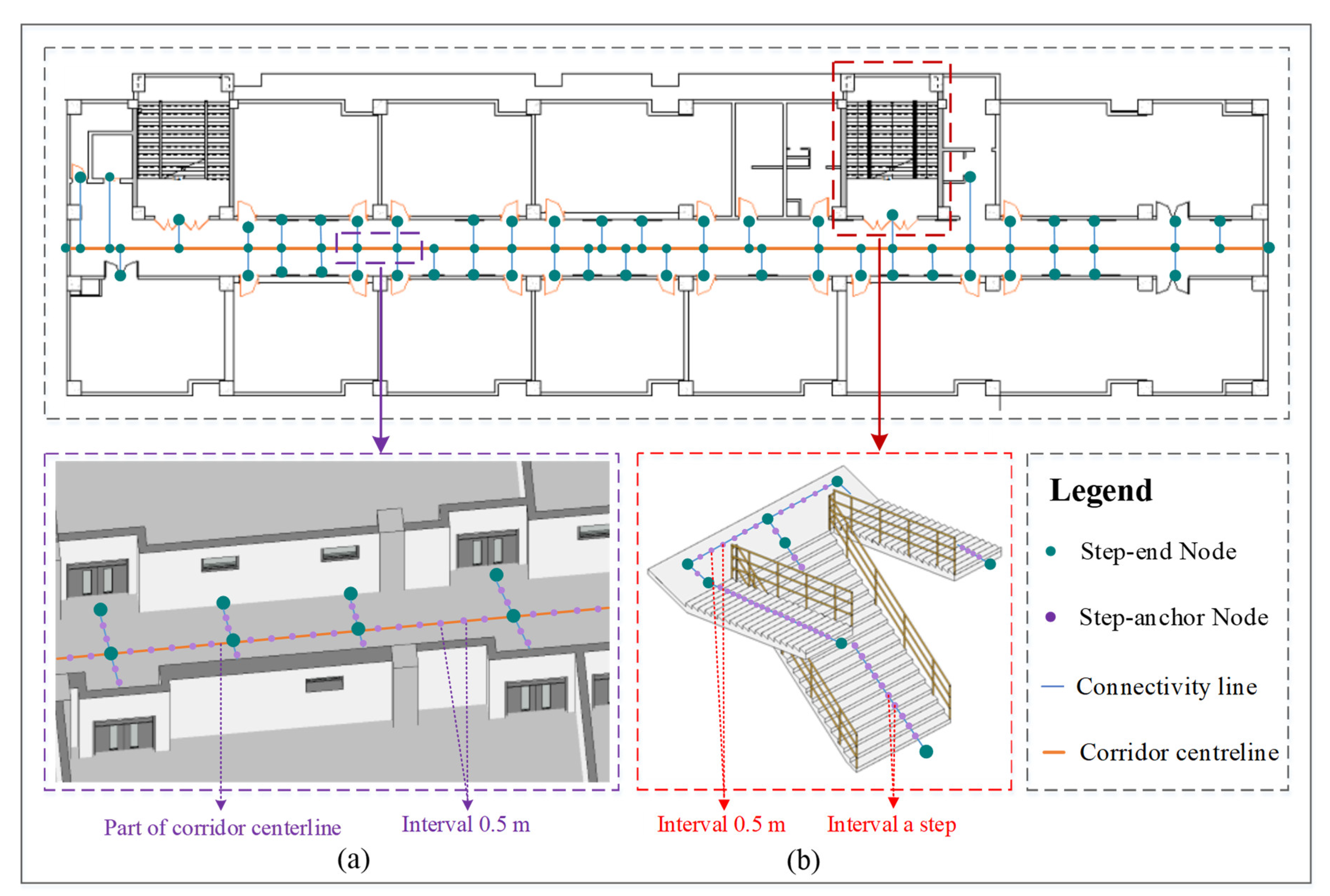
Step-anchor nodes are new nodes added to the edge of the network model on the basis of the existing nodes in the network model. It is only used to improve the accuracy of map matching and as the edge-weight reference value to assist navigation, and it does not have semantic information. The interval size of step-anchor nodes is key for adding the step-anchor node on the edge of the network model. Considering that walking is the main dependent way of human position change in the indoor environment, the user’s step distance is chosen as the interval standard of step-anchor nodes in BIMPN. As shown in Figure 6, there are two situations for the user’s step distance. One occurs in the stair stairway, because the user’s step distance is a stair step, the step-anchor node is set at each stair step. Another occurs in the horizontal direction or the stair platform of the vertical direction, where the user’s step distance is equal to his/her step length. The interval of step-anchor nodes is set at 0.5 m after referring to relevant literature [38,39] and carrying out a simple practical measurement. Considering user autonomy and practical accuracy, we will add user-defined step lengths to the future work plan and add SNs in the model based on this.
Different from step-anchor nodes, step-end nodes consist of existing nodes in the network model and carry the specifically semantic information needed for indoor positioning navigation. Apart from preventing the unlimited increase of the step-anchor node, step-end nodes are used to indicate whether it reaches the endpoint or whether requires turn to another path. As shown in Table 2, step-end nodes are set at the end of edges or the junction/turning position of two edges in different directions and its semantic information and functions are different according to its location. The step-end node is located in places where two edges in different directions intersect or turn and its semantic information is the change of path direction which is important in navigation [40]. D. Gotlib et al. [37] emphasized the importance of point locations at corridor corners and intersections. The step-end node located at the end of edges includes the end of the corridor centerline and target nodes in the network model. Besides the semantic information that target nodes have, it also has semantic information indicating that it has reached the destination or the end of path.

2.4.2. Map Matching Based on BIMPN

Map matching is the process of matching the positioning result with the corresponding path on the map, which is the prerequisite of navigation applications [41,42]. Based on the initial positioning results, map matching uses the network model and matching algorithm to map the positioning result to the path in the map. On the one hand, the situation that the positioning target deviates from the path displayed due to positioning error will not happen. On the other hand, after map matching, the positioning error of the moving target only include the radial component of the initial positioning error in the forward path, thus improving the positioning accuracy.
Map matching can be categorized into two types: point-to-point matching and trajectory matching [43]. Point-to-point methods match the positioning result point with the indoor place in light of the path. It is simple, computationally efficient and has more real-time capability than trajectory matching. Meanwhile, because the positioning results are mostly presented in the form of point coordinates [44], it is more convenient to match by using point-to-point methods. However, it relies heavily on nodes in the network and it cannot achieve a satisfactory accuracy only by the existing nodes at both ends of the edge in the network model. Therefore, BIMPN adds nodes on the edge through the SNs to improve the accuracy of map matching.
The basic idea of the map matching based on the SN between indoor positioning result and network model is: after confirming that the positioning point is in the same coordinate system as the map, a buffer is created centered on the positioning point. The SN nearest to the positioning point is determined as the positioning point matching position in the network model through calculating distance. Its process is shown in Algorithm 1.
Algorithm 1. Map Matching
  • Input: The initial positioning point p0 (x0, y0, z0); the step nodes (SN) data set.
  • Output: The positioning point matching location pt (xt, yt, zt); the distance error D e list.
  • Steps:
    (1)
    Compare the height values of the step nodes in the SN data set with the height value z0 of the initial positioning point p0 (x0, y0, z0), then select the step node S N i that has the same height, and stopping when all step nodes have been processed.
    (2)
    Centering on the positioning point p0, a buffer is created with the maximum error range E m a x plus the step size S l as the radius, and get the step node S N n in the buffer:
    Radius _ distance = E m a x + S l
               S N n = Buffer   ( p 0 ,       Radius _ distance )
    (3)
    Calculating the positioning point matching location pt (xt, yt, zt):
    The distances from each SNn to the initial position node p0 will be calculated, and then get the minimum value Dmin from them, and gain the step node pt (xt, yt, zt) corresponding to the Dmin.
    (4)
    Save Dmin as distance error D e to facilitate subsequent correction work, output D e and pt (xt, yt, zt).

2.4.3. Assisting Path Planning Based on BIMPN

Besides map matching, SN can also be used to assist the path planning for indoor navigation. Specifically, it can participate in path planning as a kind of edge weight value and estimate the user’s walking distance and time. The walking distance refers to the distance that people need to walk to move in indoor navigation. So, the distance that can be moved with elevators or other indoor facilities is not included and they only are considered in estimated time. Because SN can be adjusted according to the user’s stride, the advantage of using SN to calculate walking distance lies in its flexibility and autonomy for users. Moreover, the unit of walking distance estimated by SN consist not only of length unit (meters) but also of quantity unit (steps). Different units can be select to calculate according to actual needs, which provide more reference for navigation path planning and increase its usability under different application requirements. In this study, we propose a method for estimating walking distance and time based on SN to verify the usability of BIMPN in assisting path planning. The method is discussed separately in the vertical direction and the horizontal direction. In the horizontal direction, the walking distance and time in the horizontal direction can be estimated by calculating the number of SNs passed. The walking distance is the interval number of SNs passed multiplied by step distance and the time spent is the number of SNs passed multiplied by the walking speed. In the vertical direction, two vertical transportation modes in BIMPN are discussed, which are elevator and stair. The following describes the estimation methods and equations of these two modes of transportation:
When using the elevator, there is no walking distance in the vertical direction because users almost do not need to walk. The time spent in the elevator needs to take into account the current position of the elevator and the travel time of the elevator between each floor. The specific calculation method is as in Equation (1)
T = | F c F l | × t d + | F a F l | × t d + ( S + 2 ) × t s
where:
  • F c   is   the   current   floor   of   the   elevator
  • F l   is   user s   current   floor
  • F a   is   user s   reach   the   floor
  • S   is   the   Number   of   stops   in   the   middle   of   the   elevator
  • t d   is   the   Elevator   driving   time
  • t s   is   the   Elevator   stop   time
When using the stair, the calculation method of time spent is the same as in the horizontal direction, which can be obtained by multiplying the number of SNs passed and the walking speed. In contrast, the calculation of walking distance is relatively complicated. The stair stairway and the stair platform need to be calculated separately. Because the stair stairway can be seen as an inclined upper surface, the calculation of the walking distance of the stair stairway needs to consider both the vertical distance and the horizontal distance between the starting and the terminal of the stair stairway. Meanwhile, the calculation method of walking distance in the stair platform is the same as in the horizontal direction. The specific calculation method is as in Equation (2).
D v = D i + D p
D p = | F a F c | × ( H i 2 + W i 2 2   ) × P i × 2
D i = ( S n | F l F c | × P i × 2 ) 2 × | F l F c | ) × 0.5
where:
  • D v   is   the   walking   distance   in   the   vertical   direction ;
  • D i   is   the   walking   distance   in   the   stair   platform ;
  • D P   is   the   walking   distance   in   the   stair   stairway ;
  • H i   is   the   high   of   stair   step ;
  • w i   is   the   weight   of   stair   step ;
  • P i   is   the   number   of   stair   steps   in   each   stair   stairway ;
  • s n   is   the   number   of   SNs   passed   in   the   vertical   direction ;
  • F c   is   the   user s   current   floor ;
  • F a   is   user s   reach   the   floor ;

3. Experiment

In this section mainly describe the experiment. The Section 3.1 explains the experiment data, and the BIM model is used as the raw data in this study. The Section 3.2 explains the experimental process and results, and the experiment is divided into two parts. In the first part, as shown in Section 3.2.1, the redundant data in the BIM model are removed by lightweight. In the second part, as shown in Section 3.2.1, the information required is further extracted and reorganized including geometric, attribute, and nodes. On the basis of these, the hybrid model is built though integration of the entity model and the network model.

3.1. Experiment Data

We selected Building F of School of Geometrics and Urban Spatial Informatics on Daxing Campus of Beijing University of Civil Engineering and Architecture (longitude and latitude: 116.29606, 39.751892) as the experimental area. The building is a typical office building with six floors, consisting of five above ground and one underground. Figure 7a shows the floor plans of the buildings as generated in AutoCAD. Revit software is used to build the BIM model based on CAD drawings, as the raw experiment data, as shown in Figure 7b.

3.2. Experiment Result

3.2.1. BIM Model Lightweight

Although the description information of the BIM model is rich, it contains a lot of redundant information which is unnecessary for building map of positioning and navigation, thus reducing the transmission efficiency of computers and mobile devices. Therefore, it is necessary to simplify the BIM model before extracting information. The lightweight treatment of this experiment is mainly aimed at the complex wall structure, unnecessary lines and surfaces, redundant structure information, and so on. In the process of BIM model lightweight, redundant internal structure information in the model is removed by means of bridge, welding, sealing, deletion, and other operations, whereas geometric information such as vertex and normal of the original model is retained. Figure 8 shows the lightweight of elements model, simplifying the elements model by reducing the redundant line structure and surface structure to increase the loading speed. Figure 8a,b are the door element and the window element before and after processing, respectively. Figure 9 shows the comparison from the real scene to the original BIM model to the lightweight BIM model from a macro perspective. The comparison shows that the lightweight model reduces redundant information while still maintaining the visualization effect similar to the original BIM model.

3.2.2. D Hybrid Model of the Experimental Data

OBJ is a general standard 3D model file format with a simple format structure and supports web loading, and it is selected as the storage file format of geometric information after lightweight treatment on the model. Based on the building elements shown in Table 1, the geometric information is extracted automatically. In order to reduce the redundancy of OBJ files, non-geometric data is also deleted with reference to the data structure.
The extraction of node information is implemented by using Blender [45], which is a free open-source 3D Creation Kit. The collection of node information is a semi-automated process. First, based on Python’s development of Blender, the node information of building components, including walls, columns, doors, windows, elevators and rooms, are automatically extracted from BIM. Then the information of these nodes that are not involved in the BIM model are extracted manually, including the corridor end nodes and inflection nodes and stair nodes. Finally, SN node information is automatically generated through interpolation. The collected node information is stored in PostgreSQL database, which is an open-source database suitable for spatial data. The node information in the database is stored separately according to different directions. Then it is further classified and stored according to the floor in the horizontal direction and different traffic modes in the vertical direction.
Open Database Connectivity (ODBC) is a standard application programming interface for accessing databases and supports SQL language, and it is used to extract attribute information from BIM data. The attribute information of building component elements in the research building is extracted automatically through the ODBC connection database, filtered and collated, and then imported into the PostgreSQL [46] database for storage.
Finally, using the method described in Section 2, the information extracted is reorganized into the entity model and the network model and these two models are connected. The entity model is constructed automatically by the geometric information stored as obj file and the semantic information of the building components stored in the database. The network model is constructed automatically by the extracted node information and the edge information generated by the node. The visualization effect of the model on the web is then realized using three.js (JS 3D Library Based on WebGL) and Java.
Figure 10 shows the construction results of the network model, entity model and hybrid model. Figure 10a shows the network model including the path network skeleton, and Figure 10b shows the entity model close to the real scene. The hybrid model is shown in Figure 10c and details of the model can also be found in Figure 10d. It includes the building components elements in the entity model and the node elements in the network model. As illustrated in the legend of Figure 10, the element included in the hybrid map model include: the red box represents the deployment position of the Bluetooth sensor, and the indoor personnel is located through the interaction between the Bluetooth sensor and mobile phone signal. The purple box represents the SN, which is used in map matching for positioning results and path planning for indoor navigation. The blue ball represents the door node connected vertically with the central axis of the floor corridor. Green balls represent staircase nodes and elevator nodes, which are the key to establish the vertical connection between floors. The blue line represents the generated path. These elements correspond to the element information provided in Table 1. Moreover, the network model also shows the node’s semantic information that plays an important role in the process of pedestrian indoor navigation.
Table 3 counts the main elements of the hybrid map model BIMPN constructed from the experimental data. It includes the building component elements in the entity model and the node elements in the network model. Since the entity elements, target node, and connectivity nodes in BIMPN can correspond one-to-one with the actual ones, it can be judged whether there is data loss during the model construction by comparing the number of actual elements and the number listed in Table 3. After inspection, the model BIMPN constructed is consistent with the actual situation and there is no data loss.

4. Discussion

In this section, we aim to discuss the usability and advantage of the BIMPN. In order to verify the usability of the method in the mobile indoor positioning navigation application, we develop the Mobile Indoor Positioning and Navigation System (MIPNS) and design two different scenario cases. Section 4.1 verifies the feasibility of BIMPN by the MIPNS system, and Section 4.2 discusses the advantages of BIMPN

4.1. Verification of the BIMPN

In order to verify the effect of the BIMPN in the mobile application, the MIPNS is designed and developed as the display platform of the BIMPN. The system is based on the integrated architecture of the smart Android mobile phone and M/S (mobile/server). The main development languages are Java and WebGL (WebGL is a technology for drawing, displaying, and interacting with 3D computer graphics in internet browsers). We choose to visualize the BIMPN through the framework Three.js Library based on WebGL. The system can simulate the real 3D indoor scene, display the user’s position, and plan the path for indoor navigation. The server contains a database for storing and managing the geometry, nodes and attribute information required by the model. In addition, the application logic needs to be processed, including the automatic construction of the model and the calculation of indoor positioning and navigation. The mobile terminal corresponds to the application, which mainly completes the interaction with the user and the output of the result. In the mobile application, we choose to implement the visual rendering of BIMPN through the Three.js library framework based on WebGL. When the user enters the start and end positions in the mobile terminal, it will promptly initiate a corresponding request to the server. The server exchanges data with the database and calls the corresponding logic calculations, and returns the path results obtained to the client for display. In addition, users can set their own parameters in the personal center of the application (if not set, the default parameters will be used), such as walking speed. These data will be stored in the local database and called during calculation.
There are two different cases that are designed to verify the application performance of the BIMPN in indoor positioning and navigation. Since there are different calculation equations for the stair and the elevator in Section 2.4.3, we adopt different vertical transportation modes in two cases. In both cases, the building entrance is used as the starting point and the fourth floor is the ending point, which is a suitable distance that can be adopted to compare the error between the estimated time and the actual time. Figure 11 describes the case of building entrance-elevator-target room. Figure 11a displays the planned path using elevator in the network model. Figure 11b,c show that BIMPN in the system MIPNS and the planned path included in BIMPN from different angles. Figure 11d shows specifically the indoor positioning and path planning in the corridor scene in the system MIPNS. The purple squares represent the SNs in the model, and the red dots represent the indoor positioning location in BIMPN after map matching; the gray is the path that has been walked, and the red line is the path that is about to walk. Figure 12 describes the case of building entrance-stair-target room. Figure 12a displays the planned path using stair in the network model. Figure 12b,c show that BIMPN in the system MIPNS and the planned path included in BIMPN from different angles. Figure 12d shows specifically the indoor positioning and path planning in the stair scene in the system MIPNS. The purple squares represent the SNs in the model, and the red square on the door represents the Bluetooth deployed in the scene; the green dot represents the staircase node, the blue dot represents the staircase door node, and the red dots represent the indoor positioning location in BIMPN after map matching; the gray is the path that has been walked, and the red line is the path that is about to walk. Comparing Figure 11a–d or Figure 12a–d, it follows that the visualization effect after adding the entity model is better than the network model alone. The simulation of the real scene by the entity model can make up for the limitations of the abstract representation of the network model in visualization, and provide users with better spatial perception. In case 1 and case 2, it is assumed that the elevator is located on the underground floor and it does not stop in the middle. The user’s walking speed in the horizontal direction is 2 steps per second and the vertical direction is a stair step per second in the stair stairway respectively. The travel time and stop time of the elevator on each floor is 12 s and 10 s, respectively. The height and width of a stair step is 0.3 m and 0.15 m, respectively, and the number of stair steps each stair stairway is 20 in the research building. The walking distance, the number of SNs passed, and the time spent are shown in Table 4, rounded to the nearest integer. The error between the time calculated using our method and the real measured time is only 1 s. This proves that the concept of SN and related calculation methods we proposed are suitable for indoor time and distance measurement, which can provide reference for path planning in indoor positioning and navigation. In addition, SN can also try to integrate with other path planning algorithms to adapt to the increase in complexity. Through the test of case 1 and case 2, it is proved that the BIMPN has a satisfactory performance in visual effect, display of positioning results, and auxiliary path planning.

4.2. Highlights of the BIMPN

This study presents a 3D hybrid indoor map model for indoor positioning and navigation, named BIMPN. The current methods tend to focus on the model accuracy and modeling algorithms, while ignore how the map can better assist in positioning and navigation in the practical application. Therefore, this study chooses to start from the perspective of the practical application of the map in indoor positioning and navigation. Compared with the current models, the advantages of the BIMPN are mainly displayed in the following aspects:
Firstly, since the building map has the characteristics of complex element information, diversified application scenarios, interdisciplinary with architecture and GIS, the hybrid model is more appropriate to indoor map modeling. BIMPN is the hybrid model consisting of the network model and the entity model built by different modeling approaches, which is similar to the form of outdoor maps and caters to the user’s habit of using maps. BIMPN is not only the hybrid model but also the integration of GIS and BIM. The entity model is obtained from the BIM model as raw data material, which is reorganized for virtual visualization of indoor building environments. Different from other entity models [11,23], our entity model is a 3D building entity model with spatial relationships. It can better simulate the real indoor environment and also perform spatial queries. The network model is an abstraction of indoor space based on GIS theory, which is expressed by the node-edge structure. Different from other network navigation models [12,14,16], we have subdivided node elements from the perspective of indoor navigation applications to adapt to queries in navigation applications.
Secondly, compared with other indoor positioning navigation map models [12,18,19,20,21,22,35], BIMPN focuses more on the assistance of the map model in indoor positioning navigation and proposes the concept of SN based on the network model. Indoor path network and indoor positioning are essential for indoor navigation. Indoor navigation requires indoor positioning to obtain initial and real-time positioning information and relies on the indoor network for route planning calculations and display. Therefore, the concept of SN is proposed to assist the map model in indoor location navigation. The initial and real-time position information is matched to the path network through SN to prevent the impact of the moving target deviations from the path network on navigation and position display. Moreover, SN can participate in path planning as a kind of edge weight value and estimate the user’s walking distance.
Lastly, in BIMPN, the information extracted from the BIM is reorganized and stored to facilitate access and display model information directly on mobile devices or the Web without using any commercial software platform. This differs from many current modeling methods that import BIM models through the commercial GIS platform to form various indoor 3D GIS models [47]. The reorganization of BIM information is conducive to the better presentation of model data in GIS format and supporting spatial analysis. It also has better compatibility for the multi-source information in maps, which has different formats and needs to be converted. Obviously, this is more beneficial to the development of indoor positioning navigation applications or products.

5. Conclusions

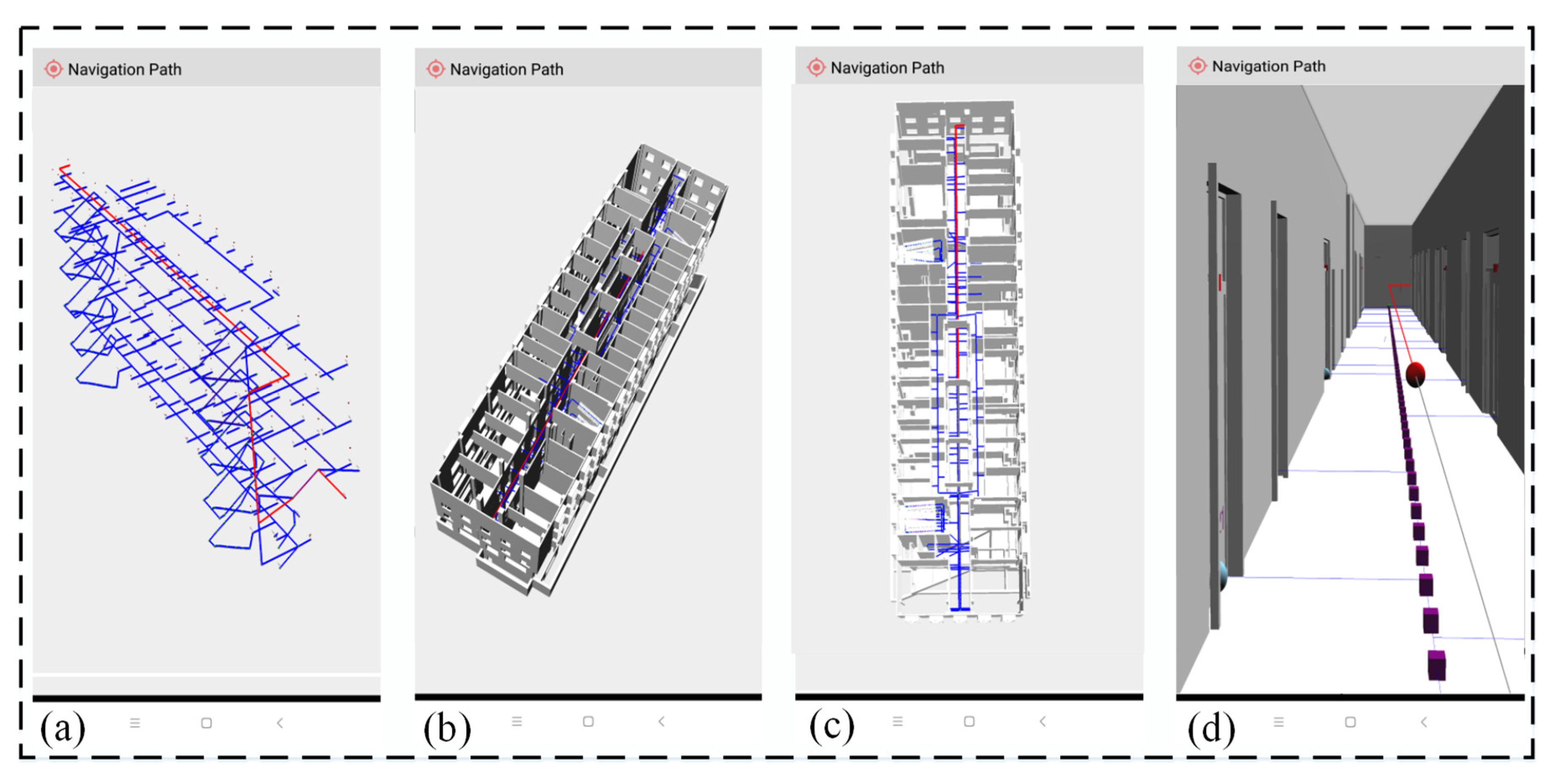
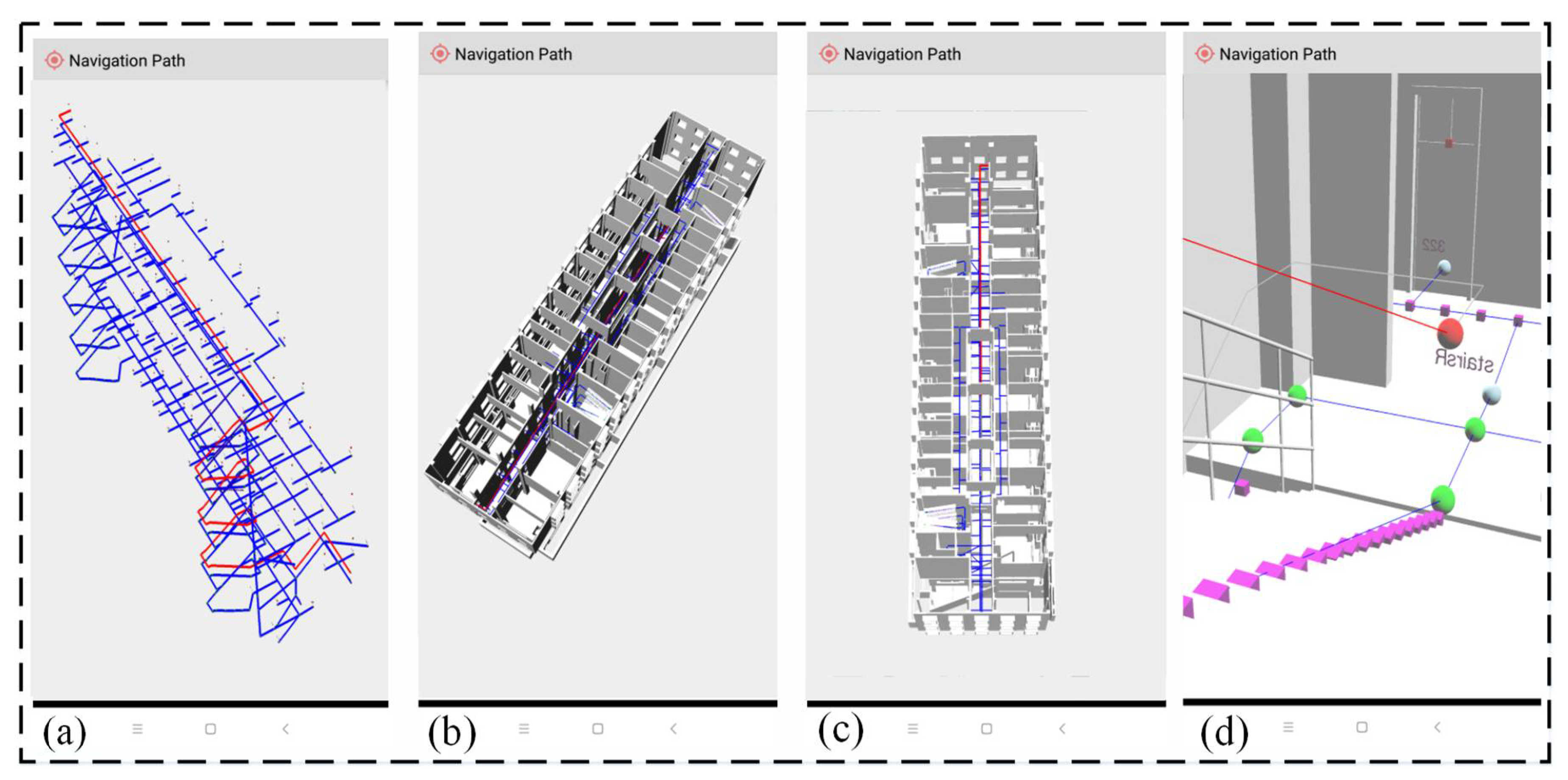
This study set out to provide a reasonable indoor map description so that the user can use it in mobile indoor navigation systems. The main points of this study could be summed up into three aspects. The first is to make up for the shortcoming of the existing hybrid model in assisting indoor positioning and navigation by putting forward a concept of Step Node (SN). Second, we consider the BIM and GIS integration and choose the entity model and the network model to build the hybrid map model to adapt to the complex of element information and diversified application scenarios in indoor. It is an expansion of the knowledge system in the field of BIM and GIS integration as well as the field of indoor map hybrid model research. Third, we developed the Mobile Indoor Positioning and Navigation System (MIPNS) to verify the practicability of BIMPN.
Different from other hybrid models, the BIMPN is not only a hybrid model based on the network model and the entity model, but also an integration of GIS and BIM. The entity model comes from BIM and consists of building elements, whereas the network model abstracts the indoor space as node edge structure according to the theory of GIS topology. In this study, the research on the relationship between the indoor map model and indoor positioning navigation is another important component. Accordingly, a concept of SN is proposed to assist map matching and the estimation of walking distance and time. In addition, we built BIMPN by reorganizing model information from BIM to have better access and display model information on mobile devices or the Web.
Although this study has no restrictions on the potential user, there are some limitations in the open space or the space with special structures. Therefore, our next step is to extend the BIMPN to make it applicable in special and open indoor environments. Moreover, mobile map loading efficiency in 5G and the collection of building map texture information are also key points we will consider in our future work. Notwithstanding limitations, this study is feasible in office buildings, hospitals, shopping malls, and other common indoor scenes, and it enhances the indoor map model research.

Author Contributions

Conceptualization, Jianhua Liu; Validation, Danqi Wen and Guoqiang Feng; Data Curation, Xu Zhang; Writing—Original Draft Preparation, Jingyan Luo; Writing—Review & Editing, Jianhua Liu; Visualization, Jiwei Hou. All authors have read and agreed to the published version of the manuscript.

Funding

This research is funded by the National Natural Science Foundation of China (No. 41301489), Beijing Natural Science Foundation (No. 4192018, No. 4142013), Outstanding Youth Teacher Program of Beijing Municipal Education Commission (No. YETP1647, No. 21147518608), Outstanding Youth Researcher Program of Beijing University of Civil Engineering and Architecture (No. 21082716012), the Fundamental Research Funds for Beijing Universities (No. X18282, No. X20099, No. X20077),and the BUCEA Post Graduate Innovation Project (No. PG2020072).

Acknowledgments

The authors would like to thank anonymous reviewers, the editors, and the scholars for their constructive comments and suggestions, which greatly improved the quality of the manuscript.

Conflicts of Interest

The authors declare no conflict of interest.

References

  1. Hashish, I.A.; Motta, G.; Meazza, M.; Bu, G.; Liu, K.; Duico, L.; Longo, A. NavApp: An Indoor Navigation Application—A Smartphone Application for Libraries. In Proceedings of the 2017 14th Workshop on Positioning, Navigation and Communications (WPNC), Bremen, Germany, 25–26 October 2017; Volume 10, p. 1109. [Google Scholar]
  2. Tan, S. A Shopping Mall Indoor Navigation Application using Wi-Fi Positioning System. Int. J. Adv. Trends Comput. Sci. Eng. 2020, 9, 4483–4489. [Google Scholar] [CrossRef]
  3. Tashakkori, H.; Rajabifard, A.; Kalantari, M. A new 3D indoor/outdoor spatial model for indoor emergency response facilitation. Build. Environ. 2015, 89, 170–182. [Google Scholar] [CrossRef]
  4. Huang, B.; Hsu, J.; Chu, E.; Wu, H.M. ARBIN: Augmented Reality Based Indoor Navigation System. Sensors 2020, 20, 5890. [Google Scholar] [CrossRef]
  5. Puttinaovarat, S.; Jutapruet, S.; Saeliw, A.; Pruitikanee, S.; Kongcharoen, J.; Jiamsawat, W.; Limpasamanon, S. Facility maintenance management system based on GIS and indoor map. Int. J. Electr. Comput. Eng. 2019, 9, 3323–3332. [Google Scholar] [CrossRef]
  6. Salih, M.H.; Teng, L.H.; Ismail, S. Indoor tracking personnel for RFID with FPGA. ARPN J. Eng. Appl. Sci. 2019, 14, 439–454. [Google Scholar]
  7. Krisp, J.; Jahnke, M.; Lyu, H.; Fackler, F. Visualization and Communication of Indoor Routing Information. In Progress in Location-Based Services; Springer: Berlin/Heidelberg, Germany, 2014; pp. 33–44. [Google Scholar]
  8. Jeamwatthanachai, W.; Wald, M.; Wills, G. Map Data Representation for Indoor Navigation. In Proceedings of the 2016 International Conference on Information Society (i-Society), Dublin, Ireland, 10–13 October 2016; pp. 1–6. [Google Scholar]
  9. Gu, F.; Hu, X.; Ramezani, M.; Acharya, D.; Khoshelham, K.; Valaee, S.; Shang, J. Indoor Localization Improved by Spatial Context—A Survey. ACM Comput. Surv. 2019, 52, 61–64. [Google Scholar] [CrossRef] [Green Version]
  10. Lin, Z.; Xu, Z.; Hu, D.; Hu, Q.; Li, W. Hybrid Spatial Data Model for Indoor Space: Combined Topology and Grid. ISPRS Int. J. Geo-Inf. 2017, 6, 343. [Google Scholar] [CrossRef] [Green Version]
  11. Pang, Y.; Zhang, C.; Zhou, L.; Lin, B.; Lv, G. Extracting Indoor Space Information in Complex Building Environments. ISPRS Int. J. Geo-Inf. 2018, 7, 321. [Google Scholar] [CrossRef] [Green Version]
  12. Mortari, F.; Clementini, E.; Zlatanova, S.; Liu, L. An Indoor Navigation Model and Its Network Extraction. Appl. Geomat. 2019, 11, 413–427. [Google Scholar] [CrossRef]
  13. Lee, J. A Spatial Access-Oriented Implementation of a 3-D GIS Topological Data Model for Urban Entities. GeoInformatica 2004, 8, 237–264. [Google Scholar] [CrossRef]
  14. Jamali, A.; Rahman, A.; Boguslawski, P.; Kumar, P.; Gold, C.M. An Automated 3D Modeling of Topological Indoor Navigation Network. GeoJournal 2017, 82, 157–170. [Google Scholar] [CrossRef] [Green Version]
  15. Li, K. INDOORGM–A Standard for Indoor Spatial Modeling. ISPRS—Int. Arch. Photogramm. Remote Sens. Spat. Inf. Sci. 2016, XLI-B4, 701–704. [Google Scholar] [CrossRef]
  16. Yuan, W.; Schneider, M. iNav: An Indoor Navigation Model Supporting Length-Dependent Optimal Routing. In Geospatial Thinking; Springer: Berlin/Heidelberg, Germany, 2010; pp. 299–313. [Google Scholar]
  17. Goetz, M.; Zipf, A. Formal Definition of a User-adaptive and Length-optimal Routing Graph for Complex indoor Environments. Geo-Spat. Inf. Sci. 2011, 14, 119–128. [Google Scholar] [CrossRef] [Green Version]
  18. Liu, L.; Zlatanova, S. Towards a 3D Network Model for Indoor Navigation. In Urban and Regional Data Management: UDMS Annual; CRC Press: Boca Raton, FL, USA, 2011; pp. 79–92. [Google Scholar]
  19. Lewandowicz, E.; Lisowski, P.; Flisek, P. A Modified Methodology for Generating Indoor Navigation Models. ISPRS Int. J. Geo-Inf. 2019, 8, 60. [Google Scholar] [CrossRef] [Green Version]
  20. Gorte, B.; Zlatanova, S.; Fadli, F. Navigation in Indoor Voxel Models. ISPRS Ann. Photogramm. Remote Sens. Spat. Inf. Sci. 2019, IV-2/W5, 279–283. [Google Scholar] [CrossRef] [Green Version]
  21. Wang, W.; Ai, T.; Gong, C. Indoor Route Planning Under Hexagon Network Considering Multi-Constrains. ISPRS—Int. Arch. Photogramm. Remote Sens. Spat. Inf. Sci. 2018, XLII-4, 693–696. [Google Scholar] [CrossRef] [Green Version]
  22. Xu, M.; Wei, S.; Zlatanova, S.; Zhang, R. BIM-Based Indoor Path Planning Considering Obstacles. ISPRS Ann. Photogramm. Remote Sens. Spat. Inf. Sci. 2017, IV-2/W4, 417–423. [Google Scholar] [CrossRef] [Green Version]
  23. Zhu, J.; Zhang, H.; Wen, Y. A New Reconstruction Method for 3D Buildings from 2D Vector Floor Plan. Comput. Aided Des. Appl. 2014, 11, 704–714. [Google Scholar] [CrossRef] [Green Version]
  24. Wu, Q.; Meng, P.; Liu, G. Reconstruction of 3D Building Model Based on the Information in Floor Plan. Traitement Du Signal 2018, 35, 303–316. [Google Scholar] [CrossRef]
  25. Yang, L.; Worboys, M. Generation of navigation graphs for indoor space. Int. J. Geogr. Inf. Sci. 2015, 29, 1737–1756. [Google Scholar] [CrossRef]
  26. Adolphi, T.; Nagel, C.; Kolbe, T.A. Multilayered Space-Event Model for Navigation in Indoor Spaces 3D Geo-Information Sciences; Springer: Berlin/Heidelberg, Germany, 2009; pp. 61–77. [Google Scholar]
  27. Noardo, F.; Ellul, C.; Harrie, L.; Overland, I.; Shariat, M.; Arroyo Ohori, K.; Stoter, J. Opportunities and Challenges for GeoBIM in Europe: Developing a Building Permits Use-case to Raise Awareness and Examine Technical Interoperability Challenges. J. Spat. Sci. 2020, 65, 209–233. [Google Scholar] [CrossRef]
  28. Zlatanova, S.; Yan, J.; Wang, Y.; Diakité, A.; Isikdag, U.; Sithole, G.; Barton, J. Geo-Information Spaces in Spatial Science and Urban Applications-State of the Art Review. Int. J. Geo-Inf. 2020, 9, 58. [Google Scholar] [CrossRef] [Green Version]
  29. Knoth, L.; Mittlboeck, M.; Vockner, B.; Andorfer, M.; Atzl, C. Buildings in GI—How to deal with building models in the GIS domain. Trans. GIS 2019, 23, 435–449. [Google Scholar] [CrossRef]
  30. Knoth, L.; Scholz, J.; Strobl, J.; Mittlböck, M.; Vockner, B.; Atzl, C.; Rajabifard, A.; Atazadeh, B. Cross-Domain Building Models—A Step towards Interoperability. ISPRS Int. J. Geo-Inf. 2018, 7, 363. [Google Scholar] [CrossRef] [Green Version]
  31. Eadie, R.; Rocks, J.; Stoyanov, V. Building Information Modeling (BIM) Software for Facilities Management (FM). In Proceedings of the XIX International Scientific Conference by Construction and Architecture VSU, Sofia, Bulgaria, 17–19 October 2019; p. 10. [Google Scholar]
  32. Wang, N.; Issa, R. Ontology-Based Integration of BIM and GIS for Indoor Routing. In Proceedings of the Construction Research Congress, Tempe, AZ, USA, 8–10 March 2020; Construction Research Council: Reston, VA, USA, 2020; p. 3. [Google Scholar]
  33. Sani, M.J.; Rahman, A.A. GIS and BIM Integration at Data Level: A Review. ISPRS—Int. Arch. Photogramm. Remote Sens. Spat. Inf. Sci. 2018, XLII-4/W9, 299–306. [Google Scholar] [CrossRef] [Green Version]
  34. Zhu, J.; Wright, G.; Wang, J.; Wang, X. A Critical Review of the Integration of Geographic Information System and Building Information Modelling at the Data Level. ISPRS Int. J. Geo-Inf. 2018, 7, 66. [Google Scholar] [CrossRef] [Green Version]
  35. Isikdag, U.; Zlatanova, S.; Underwood, J. A BIM-Oriented Model for Supporting Indoor Navigation Requirements. Computers. Environ. Urban Syst. 2013, 41, 112–123. [Google Scholar] [CrossRef]
  36. El Mekawy, M.; Östman, A.; Hijazi, I. A Unified Building Model for 3D Urban GIS. Int. J. Geo-Inf. 2012, 1, 120–145. [Google Scholar] [CrossRef] [Green Version]
  37. Gotlib, D. Selected Qualities of Mobile Maps for Indoor Navigation. Polish Cartogr. Rev. 2019, 51, 155–165. [Google Scholar] [CrossRef] [Green Version]
  38. Wang, Q.; Ye, L.; Luo, H.; Men, A.; Zhao, F.; Ou, C. Pedestrian Walking Distance Estimation Based on Smartphone Mode Recognition. Remote Sens. 2019, 11, 1140. [Google Scholar] [CrossRef] [Green Version]
  39. Ho, N.; Truong, P.; Jeong, G. Step-Detection and Adaptive Step-Length Estimation for Pedestrian Dead-Reckoning at Various Walking Speeds Using a Smartphone. Sensors 2016, 16, 1423. [Google Scholar] [CrossRef] [PubMed]
  40. Pang, Y.; Zhou, L.; Lin, B.; Lv, G.; Zhang, C. Generation of Navigation Networks for Corridor Spaces Based on Indoor visibility map. Int. J. Geogr. Inf. Sci. 2019, 34, 1–25. [Google Scholar] [CrossRef]
  41. Chao, P.; Xu, Y.; Hua, W.; Zhou, X. A Survey on Map-Matching Algorithms. In Databases Theory and Applications; Springer: Berlin/Heidelberg, Germany, 2020; pp. 121–133. [Google Scholar]
  42. Huang, Q.; Yang, Y.; Yuan, Z.; Jia, H.; Huang, L.; Du, Z. The temporal geographically-explicit network of public transport in Changchun City, Northeast China. Sci. Data 2019, 6, 190026. [Google Scholar] [CrossRef] [PubMed]
  43. Wu, Y.; Chen, P.; Gu, F.; Zheng, X.; Shang, J. HTrack: An Efficient Heading-Aided Map Matching for Indoor Localization and Tracking. IEEE Sens. J. 2019, 19, 3100–3110. [Google Scholar] [CrossRef]
  44. Gong, X.; Jiwei, H.; Siyu, L.; Jianhua, L.; Mingyi, D. Indoor Localization Method of Intelligent Mobile Terminal Based on BIM. In Proceedings of the 2018 Ubiquitous Positioning, Indoor Navigation and Location-Based Services, Wuhan, China, 22–23 March 2018; p. 3. [Google Scholar]
  45. Blender [EB/OL]. Available online: https://www.blender.org/ (accessed on 27 November 2020).
  46. PostgreSQL [EB/OL]. Available online: https://www.postgresql.org/ (accessed on 27 November 2020).
  47. Chen, Q.; Chen, J.; Huang, W. Method for Generation of Indoor GIS Models Based on BIM Models to Support Adjacent Analysis of Indoor Spaces. ISPRS Int. J. Geo-Inf. 2020, 9, 508. [Google Scholar] [CrossRef]
Figure 1. The modelling approach of the Building Information Modeling based Positioning and Navigation (BIMPN). The left represents the overall flow of modelling approach, in which the diamond describes each step in the process. The right represents the concrete content included in each step in detail, in which the gravy rounded rectangles represent the elements contained in the model and the gravy rectangles represent the concrete role of the model in indoor positioning and navigation.
Ijgi 09 00747 g001
Figure 2. Entity model. (a) Geometric boundary entity model represented by volume. (b) 3D building entity model. (c) Spatial representation of the entity model in BIMPN.
Ijgi 09 00747 g002
Figure 3. Single-layer indoor path network model in the horizontal direction. The green dots represent rooms, the yellow dots represent windows, the dark blue dots represent doors, the light blue dots represent indoor facilities, and the orange line represents corridor central line. The connection relations are abstracted as blue lines, where the window nodes are not used in general navigation, so its connection relations are represented by dotted lines.
Ijgi 09 00747 g003
Figure 4. Construction of an indoor vertical path network. (a) is the stairs transportation method and (b) is the elevator transportation method.
Ijgi 09 00747 g004
Figure 5. The connection between the entity model and the network model. (a) is the direct connection (b) is the indirect connection.
Ijgi 09 00747 g005
Figure 6. Diagram of Step Node (SN) in BIMPN. The blue-green dots represent step-end nodes, which consist of the node on the junction/turning position of two edges in different directions and the node on the end of edges including the end of the corridor centerline and target nodes. The purple dots represent step-anchor nodes. The orange line represents the corridor central line and connect relations are abstracted as blue lines. (a) indicates SN in the horizontal direction and (b) indicates SN in the vertical direction of stair.
Ijgi 09 00747 g006
Figure 7. The first floor CAD plane data of the research object (monolithic building). (a) CAD base map data provides geometric benchmarks including length, width, height, and thickness of building components for constructing building information modeling (BIM). (b) is the view of the building under modelling by Autodesk Revit®.
Ijgi 09 00747 g007
Figure 8. The door model and the window model before and after lightweight processing. (a) is door model, (b) is window model.
Ijgi 09 00747 g008
Figure 9. The data scene at various stages. The top row shows the real scene of the building being studied. The middle row shows the BIM built in the Autodesk Revit® environment. The bottom row shows the BIM simplification results.
Ijgi 09 00747 g009
Figure 10. Indoor hybrid map model construction. (a) shows the path network skeleton. (b) shows the 3D model. (c,d) shows the indoor path network model.
Ijgi 09 00747 g010
Figure 11. The indoor navigation system case 1: a route planning example of Entrance—Elevator—Target Room. (a) shows the path planed in the network model. (b,c) shows the path planed in the BIMPN. (d) shows the path planed in the real 3D indoor scene.
Ijgi 09 00747 g011
Figure 12. The indoor navigation system case 2: a route planning example of Entrance—staircase—Target Room. (a) shows the path planed in the network model. (b,c) shows the path planed in the BIMPN. (d) shows the path planed in the real 3D indoor scene.
Ijgi 09 00747 g012
Table 1. The Main Indoor Map Features in Hybrid Model of BIMPN.
ModelElementType/FunctionDirectionFeatures
Entity ModelBuilding Component ElementProvide better visual effect in indoor navigationHorizontalWall
Column
Door
Windows
Floor
Facilities
VerticalStair
Elevator
Network ModelNode ElementTarget Node, used as a starting or ending point in indoor navigationHorizontalRoom Node
Facilities Node
Connectivity Node, representing the connectivity between spacesHorizontalDoor Node
Window Node
VerticalStair Node
Elevator Node
Edge ElementExpresses the passable path in indoor spaceHorizontalCorridor
Horizontal/VerticalConnect Relation
Table 2. The Step Node in Hybrid Model of BIMPN.
NodeFunctionDirectionLocation
Step NodeStep-anchor NodeLink the results of indoor positioning to the road networkHorizontal/VerticalOn the edge
Step-end NodeTarget Node, used as a starting or ending point in indoor navigationHorizontalThe end of edgesThe target node in the network model
The end of the corridor centerline
Indicates the change of path directionHorizontal/VerticalTwo edges in different directions intersect or turn
Table 3. The Statistics of the Main Elements in Hybrid Model of BIMPN.
Floor/ElementBuilding Component ElementNode Element
Target NodeConnectivity NodeStep Node
B1 floor3242442222
1st floor5443356212
2nd floor5394848330
3rd floor6824170376
4th floor6554874376
5th floor7385064384
Table 4. The Number of SNs Passed and The Walking Distance and Time Spent in Two Cases.
CaseCase 1Case 2
Vertical ModeElevatorStairs
SNs NumberVertical Number 144
Horizontal Number129127
Walking Distance (meter)Vertical Distance 54
Horizontal Distance6463
Computing Distance64117
Time (second)Vertical Time64126
Horizontal Time6563
Computing Time129189
Actual Test Time130190
Publisher’s Note: MDPI stays neutral with regard to jurisdictional claims in published maps and institutional affiliations.

