1. Introduction
At present, the rise of new paradigms such as the Internet of Things (IoT) gives us the opportunity to retrieve data from a wide variety of sources [
1,
2] to produce more advanced and powerful services and applications. In the world of smart buildings and smart cities, we often find problems in which space information is a necessity. However, the data we normally get from the kind of sources mentioned above is not enough by itself. It is necessary to extract the heterogeneous information that data represents in order to, for example, enrich spatial models.
The sources of information we can find range from sensors (light sensors, temperature sensors, cameras, etc.) to people that collect data with their mobile devices. This source works concretely with crowdsourced data [
3,
4,
5], a kind of data that can be very useful for some platforms—for example, in OpenStreetMap (
https://www.openstreetmap.org) (OSM) for geographic information, in Waze (
https://www.waze.com/es/) for traffic status [
6], or even for collecting more complex information via social networks [
7,
8]. The opportunity offered by these types of sources allows us to represent many realities of the same space or time (e.g., in traffic, air quality, or temperature contexts). Particularly in space representations, it is very interesting to incorporate information into the space models in order to handle more complex tasks such as advanced navigation or context-sensitive reasoning. Nonetheless, the fact that every platform generally has its own way of representation makes it more difficult to combine and integrate space information from different sources. Furthermore, the increasing complexity of location-based services (LBSs) [
9] is emphasizing the limitations of the present approaches [
10,
11] to combine the heterogeneous information we are talking about in the same model. This is not a trivial problem [
12,
13], and it is necessary to rely on mechanisms to enable the combination of decoupled aspects of the modeled space, going beyond the purely geometric or topological information.
While neutral, open, and non-proprietary standards such as Industry Foundation Classes (IFC) or City Geography Markup Language (CityGML) already exist in the community for the representation of building information modeling (BIM) data, it has been demonstrated [
14] that they are too oriented to the modeling and representation of geometric and structural characteristics of the environment.
However, this is not the only problem that needs to be addressed. The lack of expressiveness and granularity with which space is commonly described, divided, and represented is another major challenge. This issue mainly concerns more complex services and systems such as advanced driver-assistance systems (ADASs) or others that are common in smart cities, where it is evident that the use of geographic coordinates is not sufficient to interpret and manipulate spatial information more abstractly. It is therefore necessary to have the possibility of enriching this geographical information and, at the same time, to be able to define spaces with different granularity that ranges from traditional coordinates to more abstract divisions of space, such as areas of danger, demographics, illumination, etc. that represent space from many points of view.
Is a fact that there is an increasing interest in new standards or mechanisms that support the creation of spatial models in order to allow the representation of the space with flexibility in integrating advanced and heterogeneous information. On the one hand, several standards have been proposed to address these problems from an indoor perspective. One of those that best understands these needs is the IndoorGML standard [
15], which provides a simple but flexible way to describe indoor spaces through the spatial organization that it employs and the way in which it represents different types of information. On the other hand, there have been several attempts to achieve something similar for outdoor spaces, like CityGML [
16]. However, one of the main inconveniences of these approaches is that they are not very flexible in terms of the information type that can be modeled, being very oriented to a visual representation of the space.
Our hypothesis is based on the adaptation of the descriptive power of the IndoorGML standard to outdoor spaces in order to make it possible to face the two challenges mentioned: (i) the integration of heterogeneous information into spatial models to describe different aspects of space and, at the same time, (ii) the incorporation of a way to divide the space more flexibly and abstractly than traditional GPS coordinates do. This work is based on the potential of IndoorGML to capture and represent different kinds of information about the same space through its vision of cellular space and multi-layered representation. First, we present a space division according to the needs thanks to its vision of space as a set of cells. In addition, we also discuss the capacity to enhance this in outdoor spaces with the use of standards that allow the space to be divided deterministically and with variable granularity (e.g., the standard Open Location Code (OLC);
https://github.com/google/open-location-code). Finally, the multi-layered representation makes it possible to represent the different types of information in a single model so that a certain region of the space can be described simultaneously from different points of view, such as lighting, WiFi coverage, geometry, or topology contexts. Although it has not been mentioned so far, note that through this proposal we manage not only to face the challenges posed, but also to achieve a solution to represent indoor and outdoor spaces together.
Thus, the major contributions of this work are: (i) it provides an approach to take advantage of the main benefits of cellular space and the multi-layered representation of the IndoorGML standard for outdoor environments; (ii) the OLC standard is integrated in the proposed approach to achieve a deterministic and flexible way to divide the space; and (iii) it specifies how to take advantage of the large amount of information available on the OpenStreetMap platform to create the desired spatial representation.
The remainder of the article is structured as follows: an overview about some of the most relevant spatial modeling standards and works is given in
Section 2. Next, the proposed approach is described in
Section 3, applying the IndoorGML standard to outdoor spaces. To conclude, a discussion of the proposed approach is provided and validated in
Section 4, and we outline directions for future work in
Section 5.
2. State-of-the-Art for Space Modeling
One of the most widely accepted standards in 3D city modeling and information exchange is City Geography Markup Language (CityGML). It is an official standard of the Open Geospatial Consortium (OGC) that was released as version 1.0 in 2008 [
16] and as version 2.0 in 2012 [
17]. This standard defines both the object types that comprise the model and the relationships that will be established between them within an urban environment. Toward this end, geometric, topological, semantic, and appearance properties are considered. CityGML can simultaneously represent a 3D model with different levels of detail (LoDs), ranging from a simple representation of buildings in 2.5D (LoD0) to a more elaborate representation of the buildings’ interiors (LoD4). However, CityGML lacks some important features for indoor space modeling and semantics. These features are critical for many indoor spatial information applications [
18]. Another important drawback to using CityGML is that it is too 3D oriented, with unnecessary and complex information in many reasoning-oriented applications and advanced services.
IFC [
19] is an open specification data format aimed at providing an interoperability solution across different software applications in the building industry. This format consists of a set of IFC classes and objects that represent an information model for both geometric and alphanumeric features in the building domain. It is a collection of more than 600 classes in continuous evolution. Among its main strengths we can highlight the communication between the different agents involved in the construction process, supporting the interaction between them through a standard format. In this sense, the data of the building model is defined only once by each responsible agent, and is shared by other intervening agents. All this results in an increase in quality, a reduction in costs, and the assurance of information consistency in the project and construction phase. For these reasons, it has been widely accepted in its application field. Nevertheless, IFC is a format based solely on the description of geometric data of buildings, leaving aside the description of outdoor environments.
The limitations of IFC have led to the appearance of extensions or complements to, for example, simplify the access control to different spaces in intelligent buildings [
20] or to detect and correct the redundancy of models based on IFC [
21] through the proposal of some algorithms. It is worth mentioning the Indoor Emergency Spatial Model (IESM) [
22], which modifies the IFC classes to support critical information relevant to emergency services, eliminating all unnecessary complexity. Even though this work identifies and addresses some important shortcomings in terms of lack of semantics, these are not fully covered yet, as the result is closely linked to the case of emergency management. Moreover, the modeling of open spaces is very limited, once again because the focus is on supporting emergency management.
Following a similar approach, another common line of work in this field is to combine the IFC and CityGML standards to provide a comprehensive view of indoor–outdoor spaces and mutually satisfy the shortcomings of both. For example, in [
23] the Unified Building Model (UBM) is presented as a solution in which both standards are combined to avoid the need of translation between them and the loss of information. On the other hand, in [
24] an extended indoor LoD (ILoD) specification is proposed to replace the CityGML LoD4 layer. This new layer aims to combine the advantages of IFC and IndoorGML in order to offer an improved LoD specification for building models, unifying indoor and outdoor spaces to meet the requirements of various applications. However, all these works still present the shortcomings and weaknesses of CityGML and IFC discussed above.
Another de facto standard that has industry support and widespread adoption by leading BIM vendors is the Green Building XML schema (gbXML) (
http://www.gbxml.org/index.html). This standard was developed to facilitate the exchange of building information stored in CAD-based building information models, enabling interoperability between different building designs and engineering analysis software tools. Because of its wide industry acceptance, suppliers of BIM software (e.g., Revit, ArchiCAD) and energy analysis applications (e.g., EnergyPlus, e-QUEST) have supported this standard, enabling the exchange of data through the Green Building Studio web service [
25]. Compared to IFC, gbXML mainly focuses on facilitating the data conversion from BIM tools to engineering analysis tools, especially building energy model (BEM) tools. As far as geometric data is concerned, this standard only accepts rectangular shapes, which is enough to perform simulations on most buildings [
26]. However, this standard is too focused on energy analysis, excluding from its scope important aspects such as outdoor space modeling, semantics, topology, navigability, etc.
OpenStreetMap is “a collaborative project to create a free editable map of the world. Rather than the map itself, the data generated by the project is considered its primary output” [
27,
28]. OSM has been one of the most successful volunteered geographic information (VGI) projects to date. This has made it possible, with the help of volunteers, to define the cartography of important parts of the Earth’s terrain. Due to its great acceptance and the possibilities it offers, OpenStreetMap has recently been used in many services (
https://wiki.openstreetmap.org/wiki/List_of_OSM-based_services), such as routing [
29,
30], disaster management [
31,
32], public transport [
33,
34], and location-based services [
35,
36]. Regarding the quality of the crowdsourced geodata, recent research [
37,
38,
39] has shown that OSM is sufficiently complete and correct compared with some proprietary solutions. There are different works that combine OpenStreetMap with other standards to reuse the large amount of information available in OSM. In [
40], for example, an attempt is made to automate the process of generating models based on CityGML from the information provided by OpenStreetMap. However, despite its acceptance in outdoor environment modeling, this solution can not be used in indoor and building modeling. All existing ideas and ongoing projects are compiled in the OpenStreetMap Wiki (
https://wiki.openstreetmap.org/wiki/Indoor_Mapping#Tagging), suggesting a provisional indoor schema (
https://wiki.openstreetmap.org/wiki/Simple_Indoor_Tagging). Despite all these attempts, the use of OpenStreetMap for indoor environments has not yet found a definitive solution.
Finally, other popular standard for modeling building geometry is IndoorGML. As specified in the definition of the standard, IndoorGML proposes “a data model and XML schema for indoor spatial information which aims to provide a common framework of representation and exchange of indoor spatial information” [
15]. The standard suggests that the space be modeled as cellular spaces—that is, a set of cells which are defined as the smallest organizational structural unit of indoor space. Each of these cells can represent different types of space such as stairwells or elevators and are characterized by not overlapping other cells and having common boundaries and a unique identifier. One of the main advantages of IndoorGML is that it is not necessary to explicitly express the relationships between different spaces that shape the building. It allows the representation of topological relationships (e.g., adjacency and connectivity) among the different indoor entities through the node-relation graph (NRG). In this way, NRG makes it possible to simplify and represent topological relationships abstractly among 3D spaces in indoor environments, such as rooms within a building [
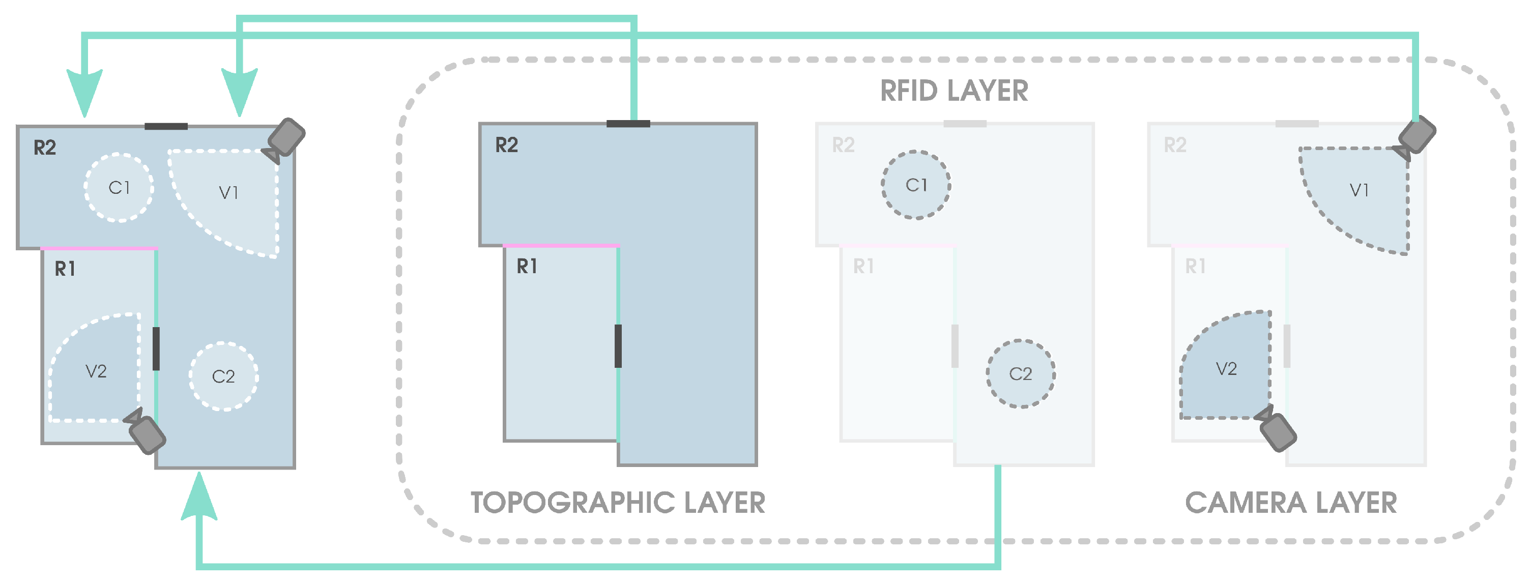
41]. Other of the main advantages of using IndoorGML as a data model is that it makes it possible to represent the same space from different points of view through the mechanism of multi-layered representation. In this multi-layered representation, each semantic interpretation layer results in a different decomposition of the same indoor space, where each decomposition forms a separate layer of cellular space. An example of this can be found in
Figure 1. In this example the space composed of two rooms is represented from different points of view in different layers: the topology and the geometry of the building in the
topology layer (cells
R1 and
R2), the coverage of the cameras in the
camera layer (cells
V1 and
V2), and Radio Frequency Identification (RFID) coverage transmitters in the
RFID layer (cells
C1 and
C2). As shown, this way of representing the different entities and relationships allows great flexibility in the division of the space and in the integration of different types of information. This approach also provides other advantages, such as the possibility of obtaining new information, as can be found in [
42].
Another of the advantages offered by IndoorGML is that it incorporates mechanisms that allow reference to objects described in external datasets, such as those already mentioned CityGML or IFC. This provides an extra level of flexibility since it will allow the resulting model to be independent of a specific application domain. This feature, combined with some emerging industry standards such as Indoor Mapping Data Format (IMDF) (
https://register.apple.com/resources/imdf/), will greatly enrich and enhance the models, since it provides a mobile-friendly, compact, and human-readable data model for any indoor space, providing useful information about orientation, navigation, and discovery.
In
Table 1 we review the main features of the surveyed standards and works. For this purpose, their capacities in different aspects were evaluated for both indoor and outdoor spaces: support for representing topology or geometry, support for navigation, if the representation of semantics is allowed, the capacity to be flexible and customized, complexity of use, user acceptance, if any support is received, and if it is a user-friendly solution. Each of these aspects are categorized with four possible values: (1) Poor, (2) Medium, (3) Good, and (4) High. To summarize, we can see that there are numerous standards and tools for the description, modeling, and representation of spaces. However, these solutions focus either on indoor or outdoor spaces but do not support the modeling of both worlds [
22,
24,
43]. This is an important limitation when the same data model considers these two types of environment. Furthermore, the minimum level of detail required is usually too high, mainly focused on providing geometric and quantitative descriptions of the different elements that comprise the space to be modeled. Although this level of detail may sometimes be necessary, it is desirable to have a lightweight version. This level of detail, for example, is accessory when the model is intended to describe whether two spaces are contiguous or whether there is a connection between them. For this reason, there are works aimed at simplifying the most popular standards [
44,
45,
46,
47] in order to obtain simpler models that are compliant with the standard. Of all the mentioned features, one of the most interesting is the multi-layered representation proposed by the IndoorGML standard. However, this standard is aimed at modeling indoor spaces, so it is not possible to apply its advantages to outdoor spaces without some modifications or extensions. Having the flexibility given by this approach to integrate heterogeneous information and the ability to understand space from different points of view is a necessity, since the smart city or smart buildings paradigms demand more than the mere geometry of space to enable true situational awareness and support for decision making. Finally, another of the most interesting features is the large number of OpenStreetMap possibilities in terms of information collection. For this reason, OpenStreetMap must be taken into account for the enrichment of space models due to its VGI nature and the large number of tools available.
3. Applying IndoorGML to Outdoor Spaces
Based on the challenges, limitations, and strengths of existing approaches for space modeling described in the previous paragraphs, here we propose a new use of the IndoorGML standard, applying the concepts and relationships established by the standard to a different dimension—the outdoor space. We present an approach that not only focuses on the application of IndoorGML to outdoor spaces, but also proposes a solution to several of the challenges mentioned previously by combining IndoorGML with other standards and tools such as Open Location Code and OpenStreetMap. On the one hand, this approach combines the potential of cellular space of IndoorGML with the Open Location Code standard, allowing a deterministic division of the space with a variable and flexible granularity. On the other hand, through the multi-layered representation we propose a way to integrate different types of information about an outdoor space regardless of their nature. This makes it possible to represent the same region of space from different points of view, thus integrating all the desired information into the same model.
Although more layers can be defined based on the information to be integrated into the model, in this paper we propose two layers that are focused on the representation of aspects of interest in outdoor spaces: (1) the olc-layer, which represents all the outdoor space according to the OLC standard allowing this space to be divided without necessarily having to label it; and (2) the building-layer, which contains more elaborate information such as existing buildings, streets, sidewalks, etc. While the OLC standard is used in the first layer, for the second we propose a solution to integrate information extracted from the OpenStreetMap platform. In this way it is possible to take advantage of the numerous information available in OSM to greatly enrich our models.
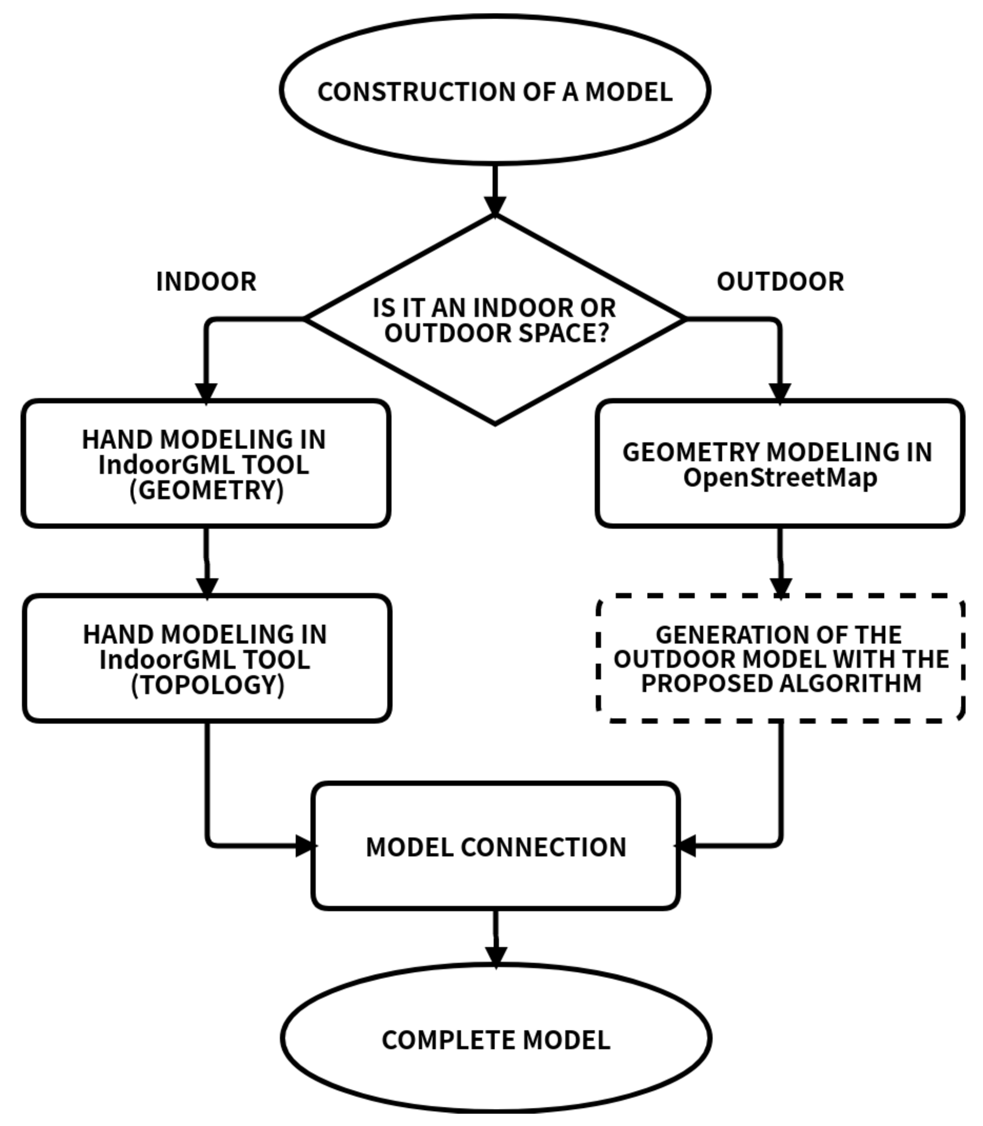
An overview of the proposed process is shown in
Figure 2. It is composed of two stages depending on the space to be represented: indoor, outdoor, or both. Indoor space modeling is carried out by directly applying the IndoorGML standard, making no contribution at this stage beyond the final connection of the indoor model to the outdoor model in which it is included. The contribution of this work mainly concerns the outdoor modeling stage, for which an adaptation of the IndoorGML standard and its combination with other solutions is proposed.
Regarding the modeling of an outdoor space, it is important that this space has been previously described in OSM format. Although in many situations this information will be available on the OSM platform (
https://www.openstreetmap.org/), it is possible that in other situations it is not available or that it is simply incomplete. In these cases it will be necessary to manually complete it using the mechanisms that OSM (
https://www.openstreetmap.org/login?referer=%2Fedit) offers to this end, or to do it locally using a tool like JOSM (
https://josm.openstreetmap.de/). From this, geometric and high-level information is extracted to build the model, such as the perimeter of buildings, areas, sidewalks, roads, etc.
When the OSM model is available, the next step (square bounded by dashed lines in
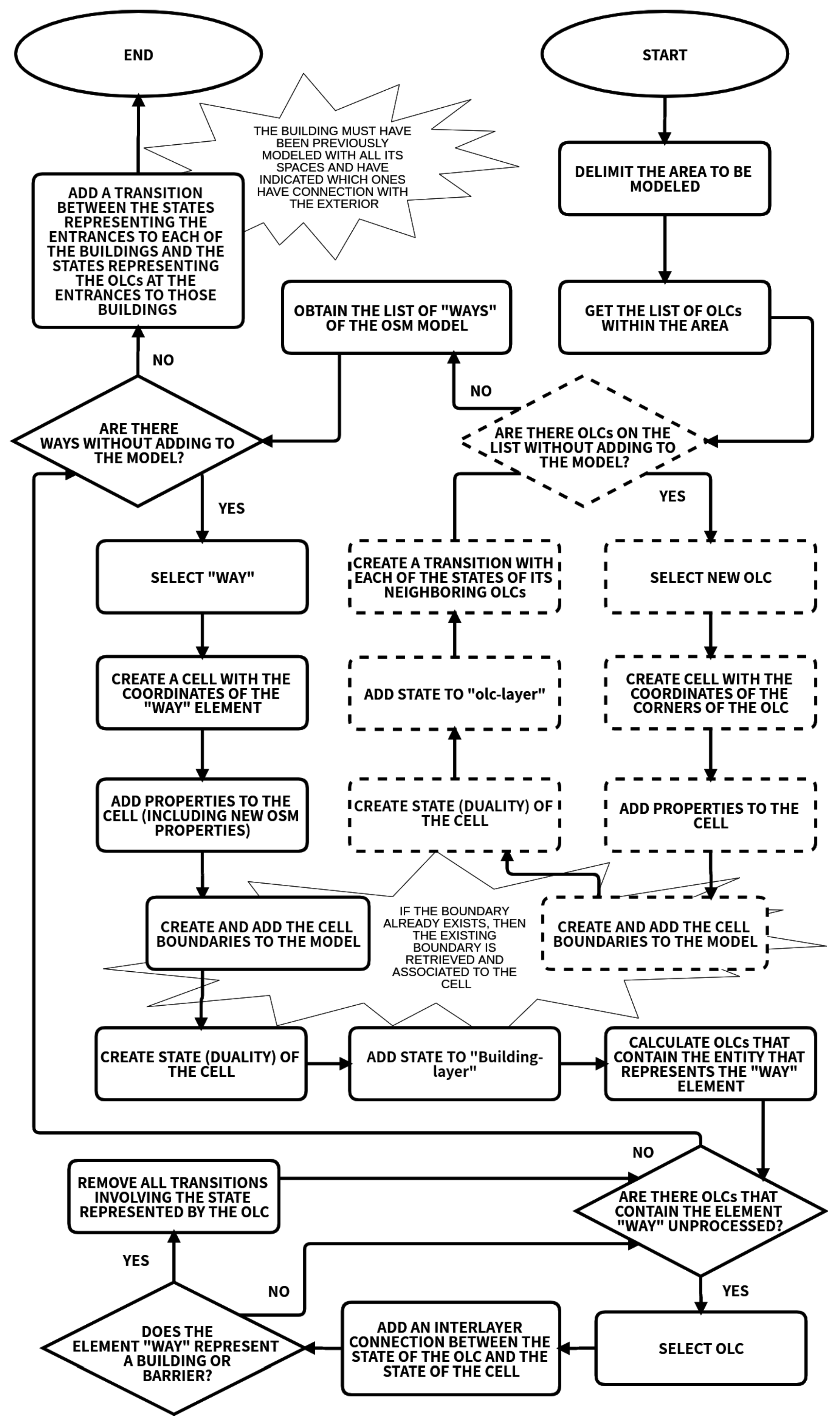
Figure 2) entails the extraction of information from it and its integration in the model, as mentioned above. The process designed for this purpose is divided into two main parts, which can be seen in
Figure 3. First, the squares bounded by dashed lines carry out the division, definition, and description of the space using the standard Open Location Code to define the
olc-layer. The second part of the diagram describes how the
building-layer is created to enrich the model with high-level information, including buildings, roads, streets, sidewalks, etc., as well as their properties. Finally, it represents how to connect both layers between them to get a joint vision of the space.
The
olc-layer definition starts by specifying the space to be modeled stating, for example, the corners of the area that bound it, the two opposite corners, or any other layout that clearly identifies the area to be modeled. Then, the set of plus codes contained in the space is obtained. These codes uniquely identify any area of the earth using the Open Location Code system. This system, developed and implemented under free license by Google (
https://github.com/google/open-location-code), also offers a direct process to convert GPS coordinates to OLC or vice versa. This work uses a plus code length of 11 digits. We can therefore represent areas of 1/32,000° by 1/40,000°(approximately 3.4 m by 2.7 m). Next, a cell from the IndoorGML standard is created to represent each of the OLC areas that conform the space to be modeled. The geometry of these cells is determined by the corners of the OLC area they represent. Furthermore, other properties of the cell are added, such as the name, identifier, surface that composes it, duality, etc. The name and the identifier of a cell are formed using the following pattern:
CELL_olc_code, where
olc_code is the name of the plus code represented by the cell. The field
gml:description is used to denote that this cell is a space defined by Open Location Code, as follows:
Usage=olc. Cells are delimited by boundaries, some of them shared among them. Boundaries are uniquely identified by an
id and characterized by their geometry and their counterpart in the dual space (also known as
duality). The identifier is formed using the following pattern:
Boundary-cell_olc_code-neighbour_olc_code, where
cell_olc_code is the cell identifier being processed at the moment, and
neighbour_olc_code, the identifier of the cell that shares that boundary. Since the same limit can be shared by several cells, a mechanism has to be established to verify whether the limit has been previously defined for a previously processed cell. If so, it would be enough to retrieve the identifier and associate it through the relation
partialboundedBy.
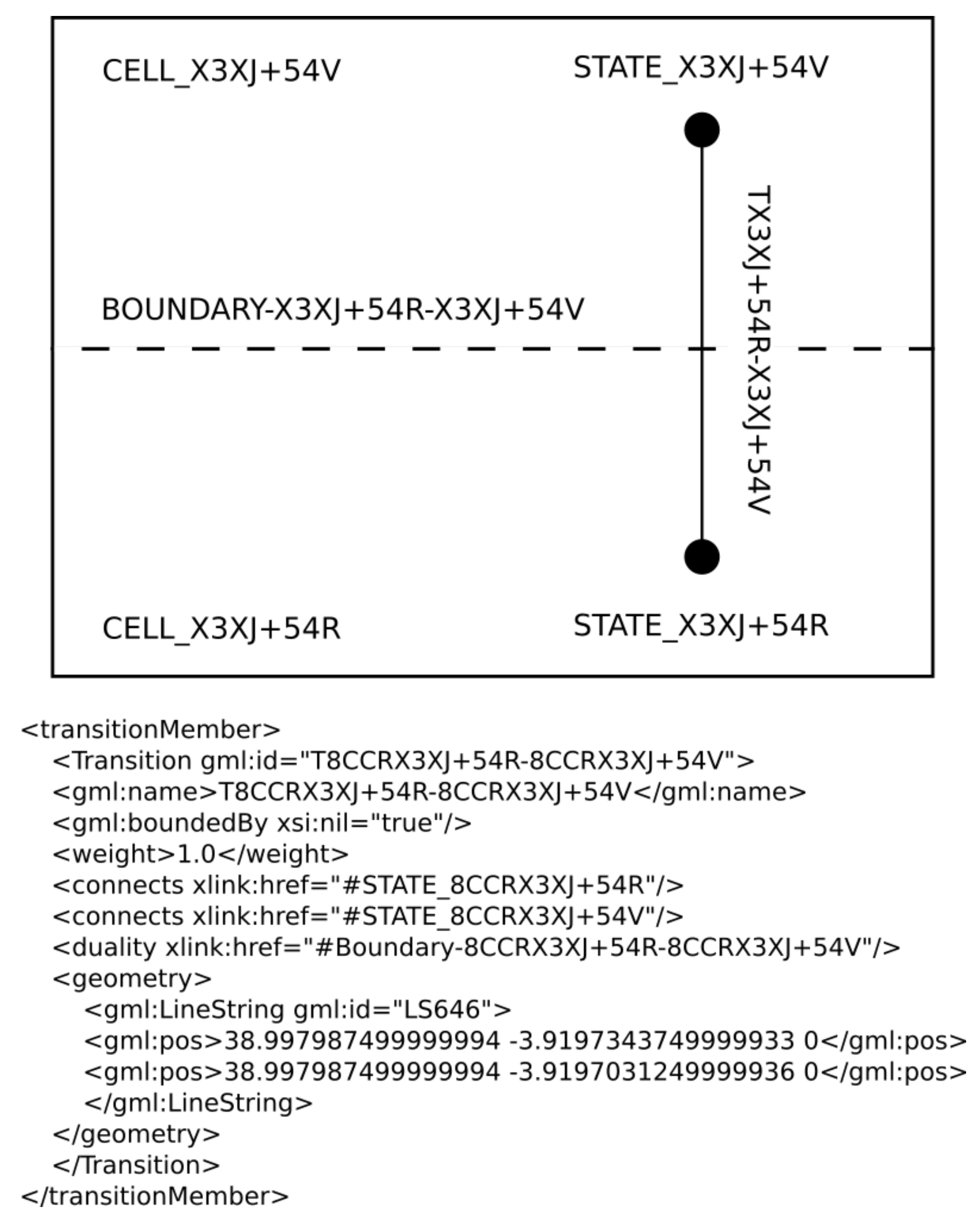
The cells and their boundaries compose the primal space of the modeled area. The dual space is where the cells are mapped to states and the boundaries as transitions between them. Thus, there is a dual counterpart for each cell and boundary. An example of this can be seen in
Figure 4, in which the primary space is composed of two cells (CELL-X3XJ+54R and CELL-X3XJ+54V) and a boundary (BOUNDARY-X3XJ+54R-X3XJ+54V), while its corresponding dual entities will be the two states (STATE-X3XJ+54R and STATE-X3XJ+54V) and the transition (T-X3XJ+54R-X3XJ+54V) between both states. When a cell represents a plus code area, the state of that area is determined by the geometric center of the plus code area to which it is associated. This state is univocally identified by the following pattern:
STATE_olc_code, where
olc_code represents the plus code name of the cell whose state is being defined. The transitions between states are established on the basis of the vicinity relation (sharing a boundary) between pairs of cells. These transitions have a unique identifier with this pattern:
T-cell_olc_code-neighbour_olc_code, where
cell_olc_code and
neighbour_olc_code are the identifiers of the states connected by the transition. The field
connects of the IndoorGML standard is used to indicate the link between two states. Thus, a transition has two properties to indicate the adjacent or neighboring states (cells or OLC areas in their primal counterpart). The geometry of a transition is characterized by the two points of the states it connects. The primal counterpart of the transition, for the case in which each cell represents a plus code area, is given by the boundary between the two areas or the boundary shared by the two cells. Thus, the identifier of the transition in the dual space (pattern
T-cell_olc_code-neighbour_olc_code) is determined by the identifier of the boundary of the primal space previously described (pattern
Boundary-cell_olc_code-neighbour_olcode).
Figure 4 shows an example of two OLC areas,
X3XJ+54R and
X3XJ+54V, located in Ciudad Real (Spain). These two areas have been modeled as cells, one for each plus code area with the identifiers
CELL-X3XJ+54R and
CELL-X3XJ+54V. These cells have the states
STATE-X3XJ+54R and
STATE-X3XJ+54V as their dual-space counterparts. Both cells share the boundary
BOUNDARY-X3XJ+54R-X3XJ+54V with the transition
T-X3XJ+54R-X3XJ+54V as its counterpart in dual space. The corresponding XML description of the transition is also included.
Next, the model is enriched with more abstract information through the creation of the
building-layer. To this end, the information available in OpenStreetMap is used—more specifically, the
way concept. This element is represented by an ordered list of nodes (between 2 and 2000), which in turn represents a polyline. When used as a
closed way, this is used to represent elements such as buildings or forests. When defined as a
open way, it represents elements such as roads or rivers. A cell is created with the same geometry as the entity
way to which it is associated. An element
way is defined by a set of OSM
nodes with a given latitude and longitude. The process of creating a cell with the same geometry as the element
way to which it is associated therefore consists of adding a point to the cell geometry for each OSM
node that composes the element
way. The cell name and identifier follow the pattern:
CELL_osmName, where
osmName is the name of the element
way to which it is associated. The rest of the typical properties of an IndoorGML cell are also added. The field
gml:description of the IndoorGML standard is used to incorporate more abstract information with a higher semantic load into the model. This information is extracted from the properties (
https://wiki.openstreetmap.org/wiki/Map_Features) of the element
way like the intended purpose of the building (education, sports, transport, emergencies, etc.) or ground base (paved, mud, asphalt, etc.). Two concrete examples are shown below:
<gml:description> area=yes surface=mud </gml:description>: these labels indicate that the cell represents an area and that its surface is muddy.
<gml:description> amenity=gas building=yes <?gml:description>: these labels indicate that this cell represents a building and that it corresponds to a gas tank.
The state of the dual space is defined for every cell, univocally identified by the following pattern: STATE_osmName, where osmName is the name of the element way to which it is associated. The state corresponds to a representative point of the element way that is inside the area being represented. The building-layer is comprised of cells representing specific areas such as buildings, parks, roads, barriers, etc.
The next step is to connect the layer
olc-layer to the
building-layer. First, it is necessary to identify which plus code areas lie within the geographical area defined by each element
way. Then, they are connected using the
Inter-Layer relations defined in the IndoorGML standard. According to [
15], this type of relation connects different layers or spaces of a model. Thus, while
Intra-Layer relations (i.e., transitions) denote adjacent cells within the same model space,
Inter-Layer relations denote relations between cells belonging to different space models.
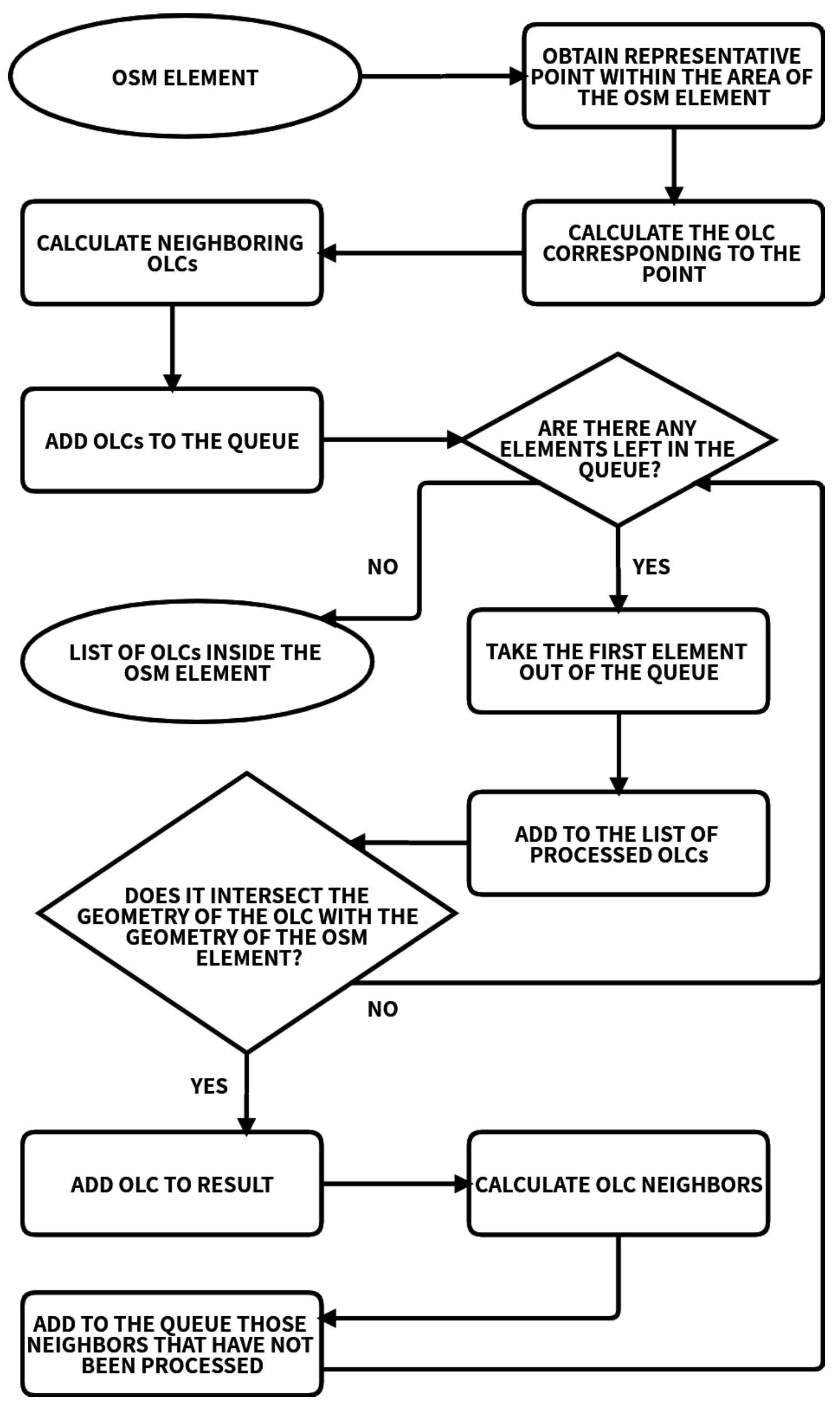
The process proposed to calculate the set of plus codes that cover the area delimited by the
way element is represented in
Figure 5. Starting from a point contained in the area defined by the geometry of the element
way, the 11-digit plus code containing that point is calculated. Next, the adjacent OLCs (north, south, east, and west neighbors) are identified and added to a queue of elements. The OLCs in this queue are processed to determine whether they are contained within the area defined by the geometry of the
way element. If so, their neighbors are added to the queue and the corresponding OLC is added to the result. In other case, they are discarded. The final result contains the list of OLCs inside the area of the geometry defined by the
way element. For each of these OLCs, an
InterLayerConnection relation is created to link the state of the cell associated to the OLC and the state of the cell associated to the
way element.
The process of connecting layers also ensures consistency in the transitions established between the states of the olc-layer. The building_layer contains information about those elements of type way that, by definition, block the transit, such as buildings or barriers. During the connection of both layers the transitions of the olc_layer established between states which correspond to non-navigable ways are removed.
In the next step, it is necessary to connect the outdoor model with the indoor model of every building included in the corresponding outdoor model. To do this, those cells containing the label Usage=Entrance are identified for each indoor model. For each of these, the OLC areas that contain it are calculated with an accuracy of 11 digits. Next, a transition is added which associates the state corresponding to the cell of the indoor model to the state corresponding to the OLC area of the outdoor model. Finally, it is only necessary to integrate all the information (cells, states, transitions, etc.) of the indoor models of buildings in the resulting model. It is important to mention that before integrating the building model it is necessary to check which is its coordinate reference system (CRS). In this way, we can meet two possible situations. On the one hand, it is possible that the indoor space is represented through the global CRS, so it will not be necessary to perform any type of conversion: all information will simply be integrated directly into the resulting model. However, in some situations the building model may be represented in its own local CRS. If this is the case, it will be necessary to carry out the conversion through the following steps:
First it will be necessary to have the origin point of the target CRS (or global CRS) .
Perform the scaling process through the rescaling factor .
Perform the rotation process through the rotation angles , along -axis.
Perform the translation process through the translation vector .
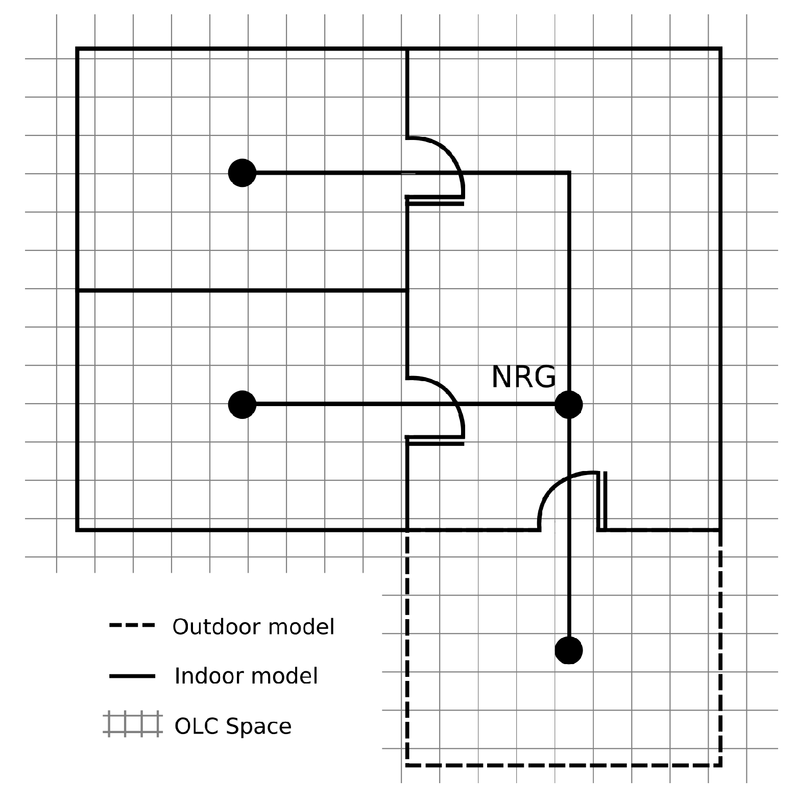
Figure 6 illustrates a connection example and how, from it, you can obtain a single NRG (a graph (
V, E) where
V is a set of nodes representing cells in the indoor space and
E is the set of edges of topological relationships between cells) describing the global connectivity of the model.
4. Experimental Validation
The proposed work was experimentally validated by modeling an area combining indoor and outdoor spaces, using for this purpose the methodology presented in this work. The indoor model was the building of the Institute of Information Technologies and Systems of Ciudad Real (Spain), but its representation was modified to incorporate a greater variety of details. Once this model was generated, it was used by a routing system with the objective of calculating two types of routes in which different types of information were taken into account. On the one hand, simpler routes were calculated considering only the shortest path. On the other hand, the route system calculated more complex routes taking into account properties available in the model, such as the type of surface. In this way, the system prioritized those routes where the traversed surfaces favor navigability. Through this use case we intended to validate the proposed approach to apply IndoorGML to outdoor environments and demonstrate how the resulting model can be very useful in a real application, such as route calculation.
The selected space covered an area of 9877.7 m, with a width of 103 m and a height of m with the following components:
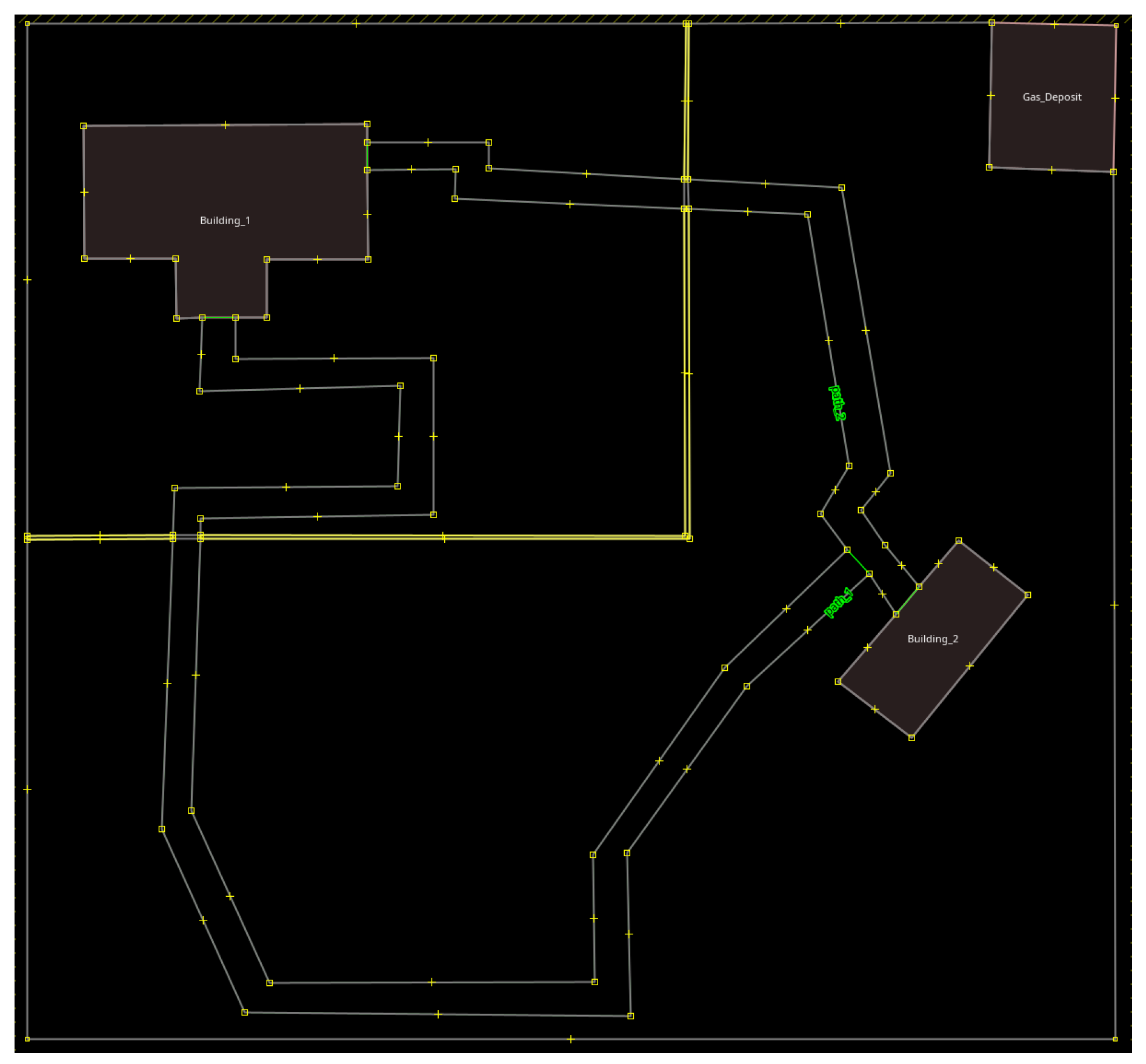
Buildings: The space contained a total of three buildings, defined by the identifiers Building_1, Building_2, and Building_3. Building_1 is an office block, Building_2 is a school, and Building_3 is a building used for gas storage.
Areas: The space contained a total of four areas, defined by the identifiers area_1, area_2, area_3, and area_4. area_1 and area_2 are located in a grassy surface, area_3 in a surface with gravel, and area_4 in a muddy surface.
Paths: In the space a total of two paths can be found, defined by the identifiers path_1 and path_2. Both paths are in asphalt surfaces.
Walls: The space contained a total of three walls, defined by the identifiers wall_1, wall_2, and wall_3.
As the scenario under consideration did not exist in OpenStreetMap, it was necessary to describe it. To do so, we used JOSM (
https://josm.openstreetmap.de/), free software for editing data in OpenStreetMap. This editor described through
nodes and elements of type
way the geometry of the different buildings and areas that were considered in this use case. Later, these entities were enhanced with the properties supplied by OpenStreetMap. All entities had a common label,
name=*, which was used to name them accordingly. The rest of the tags are listed below:
Buildings: To indicate that an entity in OpenStreetMap is a building, the key
building (
https://wiki.openstreetmap.org/wiki/Key:building) should be used. So, we can simply use
building=yes or use a value to describe the type of the building, such as those used to indicate the different types of buildings in the use case:
building=office for offices or
building=school for school. The case of the gas tank is somehow more sophisticated, as it is also necessary to use the tag
amenity (
https://wiki.openstreetmap.org/wiki/Key:amenity), thus the definition of this entity was done with the key-value pairs
building=yes and
amenity=gas.
Areas: To specify in OpenStreetMap that an element
way (
https://wiki.openstreetmap.org/wiki/Key:area) represents an area, the key
area=yes should be used. Additionally, to indicate the surface of an element the key
surface=* is used, where
* would be replaced with the corresponding value (
https://wiki.openstreetmap.org/wiki/Key:surface). So the definition of the different areas of the use case were defined as follows:
area=yes and
surface=grass for areas
area_1,
area_2, and
area_3;
area=yes and
surface=mud for area
area_4.
Walls: The key
barrier=* (
https://wiki.openstreetmap.org/wiki/Key:barrier) establishes that it is a physical structure that blocks or impedes movement through it, replacing the
* with the corresponding value. Thus, the entities
wall_1,
wall_2, and
wall_3 of the use case were defined by the following tag:
barrier=wall.
Figure 7 shows the result modeled in OpenStreetMap for the proposed use case.
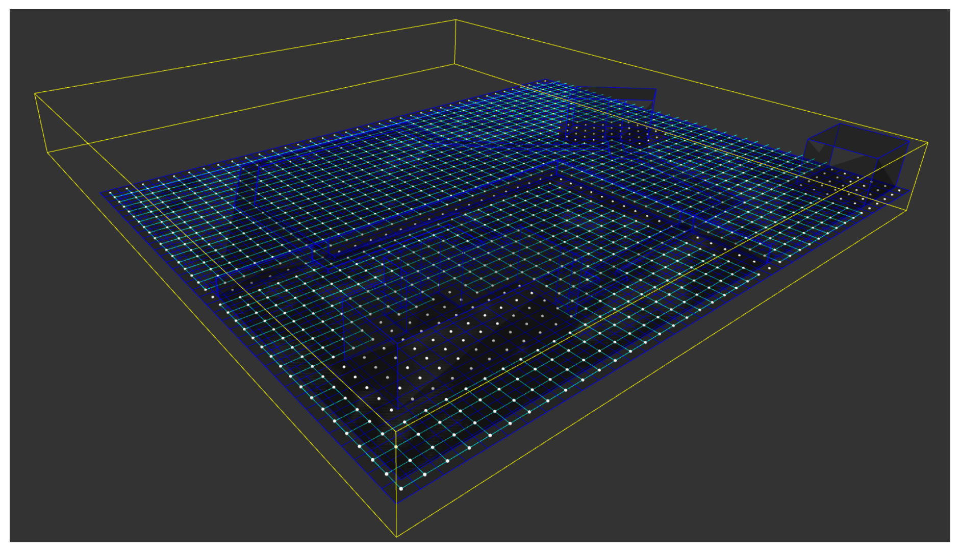
Then, the proposed approach was applied to this OSM model to obtain a space representation according to the IndoorGML standard, with two well-differentiated layers. The olc-layer was comprised of 4251 states associated to their corresponding cells, describing the OLCs contained in the area defined by the use case. The building-layer was composed of 12 states associated to their corresponding cells, representing the different elements of type way contained in the OpenStreetMap model from the previous step.
In addition to the layers, states, cells, and their corresponding boundaries, the resulting model contained all the transitions identifying the connections between the different states and the relations
InterLayerConnection specifying which states of the layer
olc-layer overlap with the states of the layer
building-layer. The resulting model is illustrated in
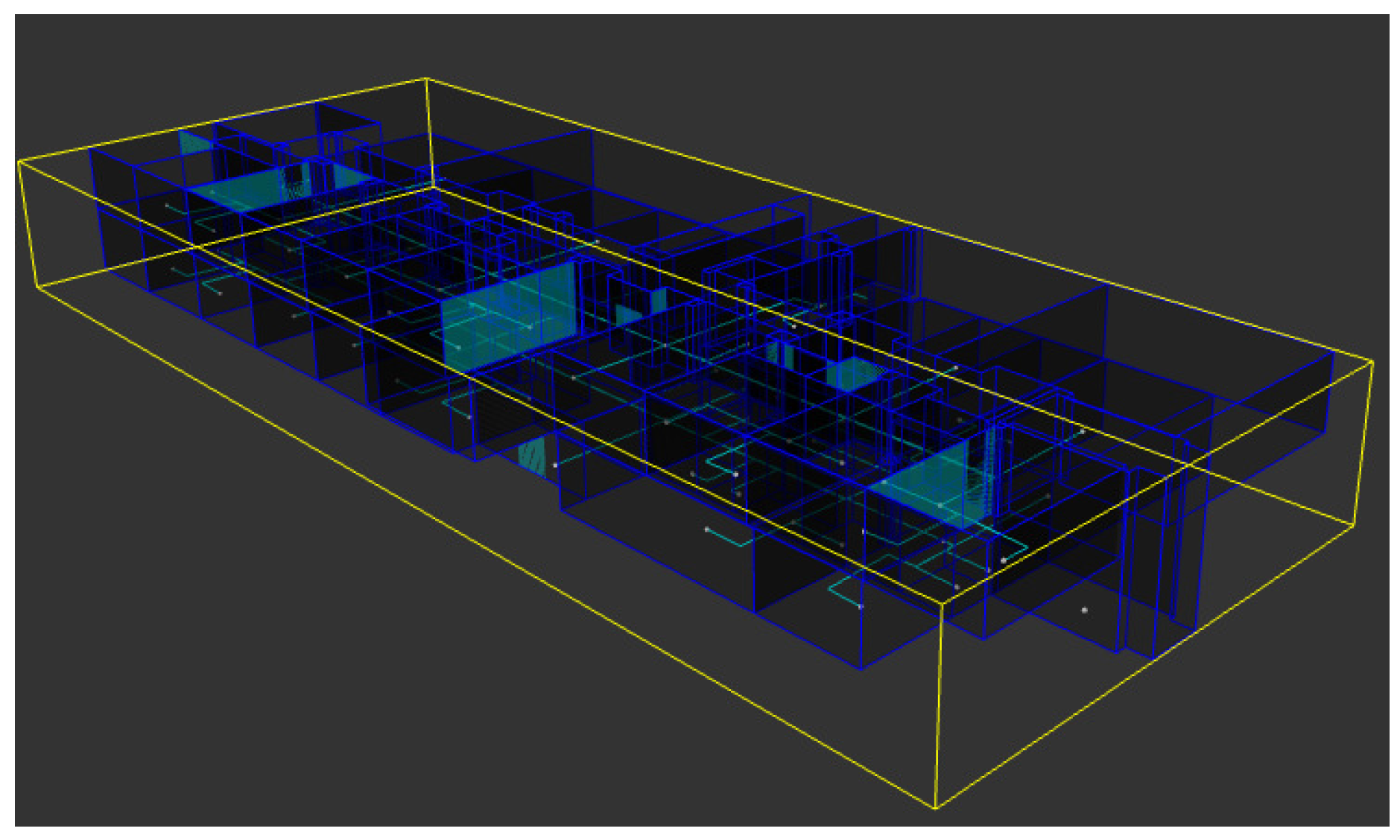
Figure 8 using the IndoorGML-Viewer (
https://github.com/STEMLab/IndoorGML-Viewer). The different cells delimiting spaces OLC and the buildings can be seen with navy blue lines, as well as the transitions (in pale blue) between states (white dots).
To work with an indoor space,
Building_1 was modeled, corresponding to a real office building (Technology and Information Systems Building mentioned at the beginning of this section). This model was made using the JIneditor (
https://github.com/STEMLab/JIneditor), an open-source Java program that provides tools for simple editing of IndoorGML data. Although JIneditor has been selected, there are several tools recommended by OGC (
http://www.indoorgml.net/resources/) that support the editing of IndoorGML models, such as Infactory or InEditor. A screenshot of the building model is shown in
Figure 9.
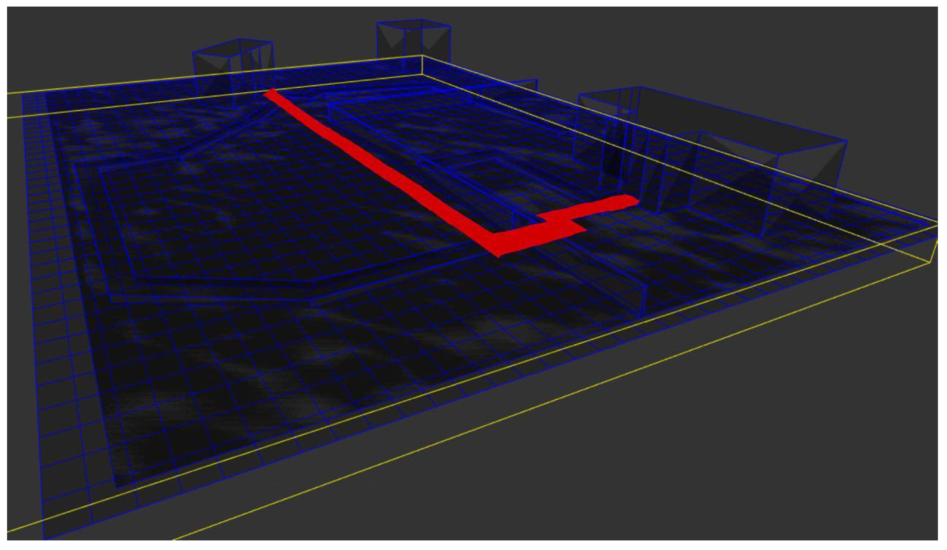
As mentioned at the beginning of this section, the model was used in a routing system to generate a point-to-point path to validate the proposed work.
Figure 10 represents the simplest case, where the route obtained to go from a room on the second floor of
Building_1 to the entrance of
Building_2 corresponds to the shortest path, in terms of the number of cells to be visited, without taking into account any other aspects. To achieve this result the following procedure was followed. First we created a graph where each state associated to the
olc-layer was represented by a different node of the graph. Additionally, for each transition between the states of this layer, a link was created in the graph between the nodes that represent those same states. Note that when considering only the number of covered cells, the weight of all edges was set to value one. Finally, in order to calculate the route, the Dijkstra algorithm was used. Note also that since the NRG from which the graph was constructed represents both indoor and outdoor connectivity, it was possible to calculate routes between any two points of the model regardless of their nature, even from indoor to outdoor spaces and vice versa.
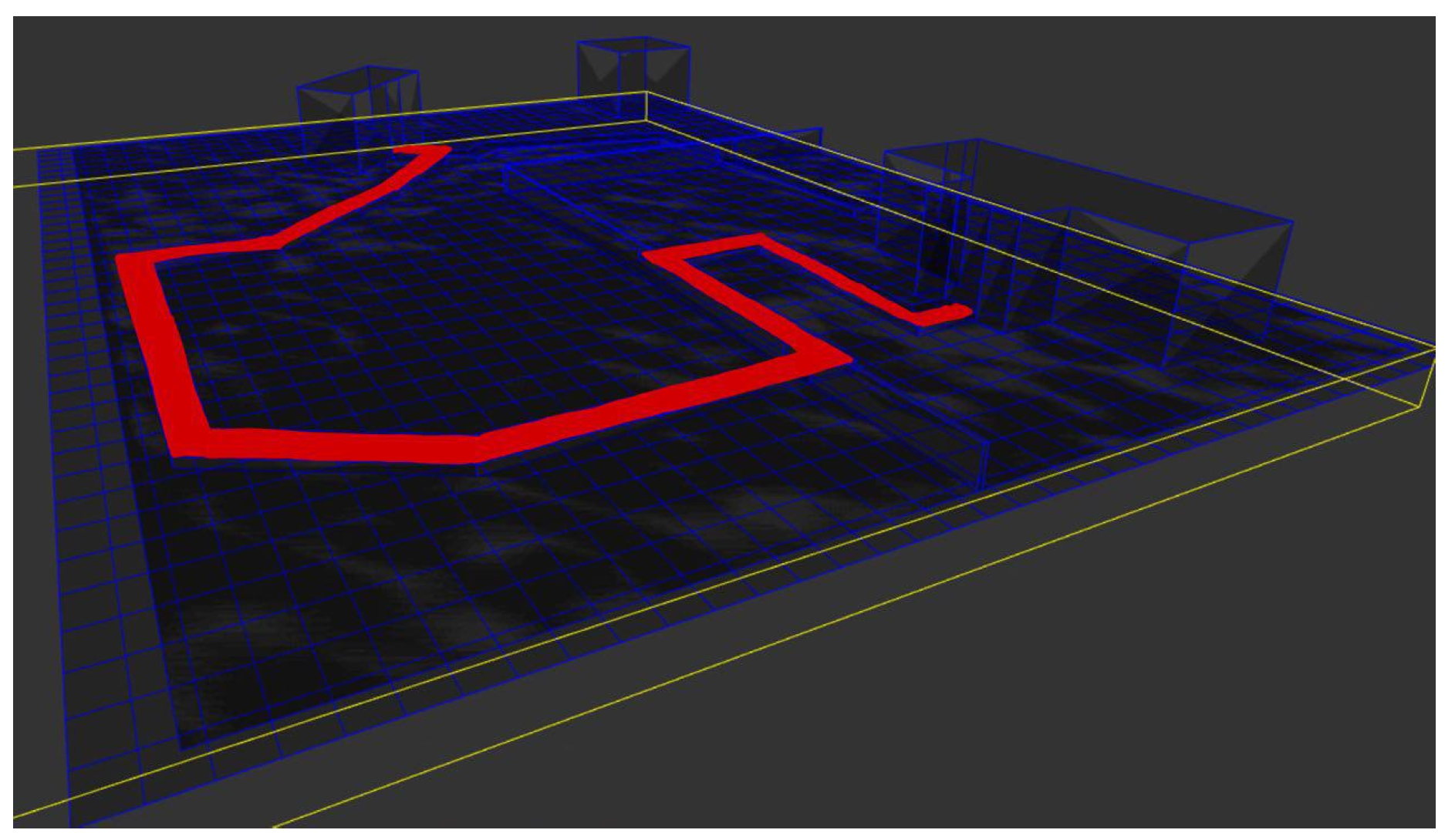
Although the calculation of routes between indoor and outdoor points already constitutes an advancement over the state-of-the-art, the true potential of the proposed approach lies in the possibilities that result from the availability of higher-level information. In this case, routes can be calculated considering more advanced aspects such as the type of area, the use of the building, or the restrictions associated to reduced mobility. For example, the route shown in
Figure 11 can be offered to people in wheelchairs because it promotes firm surfaces such as asphalt over others such as grass. To this end, it is only necessary to change the weight of the edges of the graph taking into account the information provided in the model. In this case, the surfaces whose transitability is simpler (e.g., asphalt) have lower weights associated, while on the contrary, those surfaces that are less suitable for transit (e.g., mud) have higher weights associated. Listing 1 shows the pseudocode of the process for the construction of the new graph. As it can be observed, it is only necessary to assign a specific weight to the edges of the graph according to the type of surface that corresponds with the cell of the
osm-layer in which the OLC cell represented by the node of the graph is contained.
	     Listing 1: Pseudocode for the creation of the graph, taking surfaces into account.
          surface_weighs = {asphalt : 1, grass : 10, mud : 100}
	  graph = newGraph ( )
	  olc-layer = getLayer ("olc-layer")

	  for each state in olc-layer:
	    node = newNode(state)
	    graph.addNode (node)

	  for each transition in olc-layer:
	    state1, state2 = transition. getConnectedStates ( )

	    interConnectedStateInOSMLayer1 = state1.InterconnectedState (osm-layer)
	    interConnectedStateInOSMLayer2 = state2.InterconnectedState (osm-layer)

	    surface1 = interConnectedStateInOSMLayer1.Surface ( )
	    surface2 = interConnectedStateInOSMLayer2.Surface ( )

	    weight = max (surface_weighs [surface1], surface_weighs [surface2])
	    graph.addEdge (transition, weight)
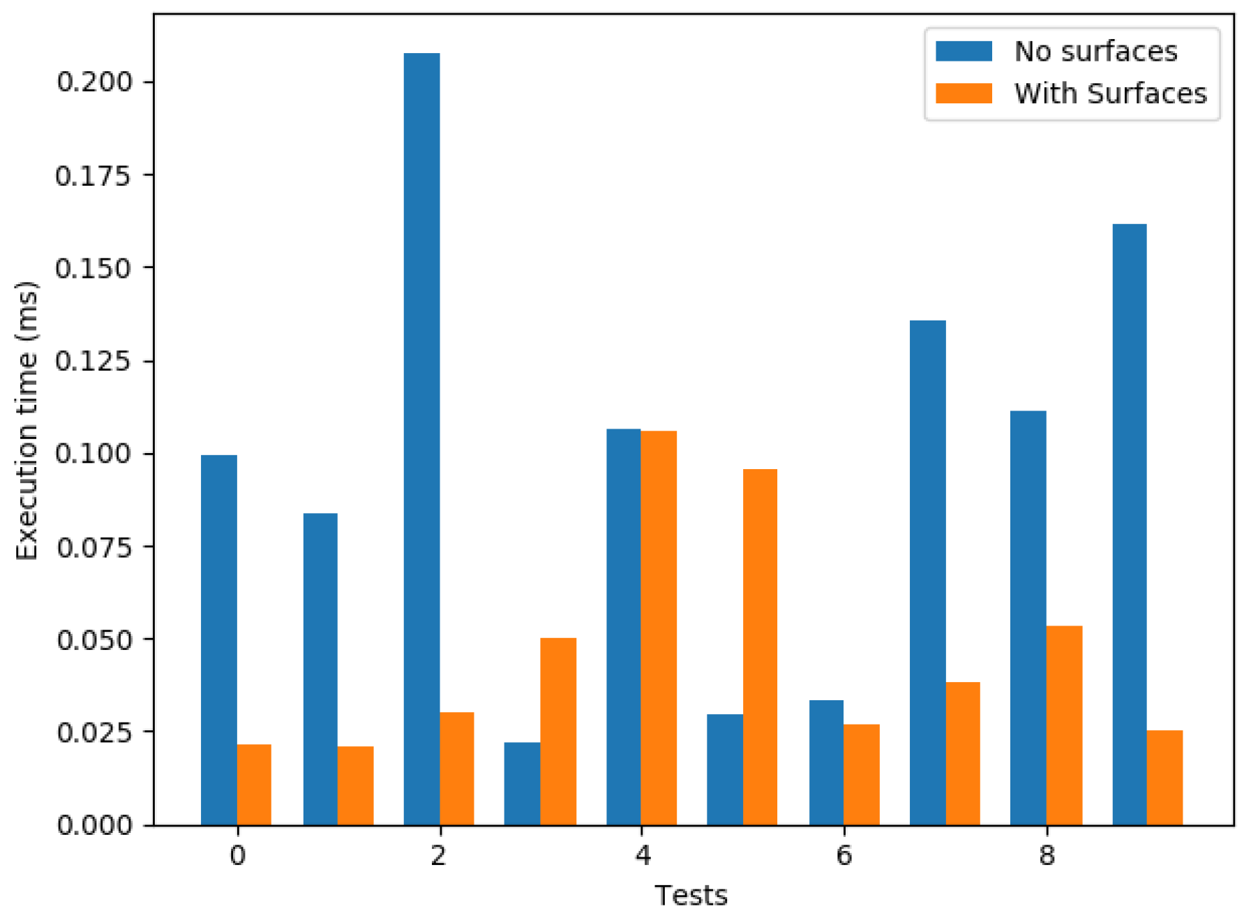
Figure 12 presents the results of a battery of tests performed on the proposed use case. The purpose of these tests was to verify that the model is fully applicable to the case of route calculation and check if it brings real benefits in the quality of the routes. Toward this end, 10 pairs of OLC cells of the model were randomly calculated, which would serve as the origin–destination of each of the tests. For each of these pairs of cells, the calculation was executed 100 times for both variants (considering surfaces and not considering them) and the mean of the obtained results was calculated. Each variant was executed 100 times in order to obtain uniform results and correct deviations caused by external issues to the execution of the algorithm (higher load in the PC, operating system, etc.). The specification of the equipment in which the tests were performed corresponds to a basic equipment (
https://mega.nz/#!rR4UUapQ!-lf5ogm6-8V8sEidxpR-JLWUKYPyVX0D-2DQi2DBWX4). As can be observed, the obtained times were below 200 ms, demonstrating that the proposed model is applicable, at least in scenarios of similar characteristics where it is required to calculate routes.
5. Conclusions
The emergence of paradigms such as the Internet of Things (IoT), smart city, or smart buildings demands more advanced space representation systems than those normally employed due to the large variety of information that is generated. Toward this end, it is necessary to address the limitations of standards that, to date, do not provide enough flexibility in the integration of heterogeneous information, in the division of space, or that simply do not support the combined modeling of indoor and outdoor spaces. Furthermore, these standards tend to focus on geometric aspects, with the low level of semantic expressiveness that generally prevents a comprehensive interpretation of the space or the impossibility of representing the same space from different points of view. Although these problems have been tackled in isolation, it is necessary to find a solution capable of addressing all these challenges as a whole.
The work presented in this paper proposes a comprehensive approach to the aforementioned challenges, based on the application of the IndoorGML standard to outdoor spaces. The multi-layered nature of IndoorGML is used to propose different levels of abstraction, thus incorporating the advantages offered by other standards such as Open Location Code or OpenStreetMap. The Open Location Code standard is used to represent the space to be modeled at the lowest abstraction level. At the same time, the OpenStreetMap system divides the space according to more abstract entities, such as streets, parks, gates, etc., while also incorporating associated semantics. Leveraging the mechanisms offered by IndoorGML, all these layers are related through inter-layer relations, thus connecting the different levels of abstraction and points of view according to the needs. Finally, the proposed approach also supports the integration of IndoorGML models of buildings contained in the region of the modeled space, resulting in a single model with indoor and outdoor information.
Ultimately, it is worth mentioning that, although the examples shown in the validation process were applied to navigability issues, the combined description of indoor and outdoor spaces with information that goes beyond the purely geometric level opens up many possibilities in the field of intelligent cities and buildings. One feasible application could be the categorization of the space by information implied in the explicit definition of the model. That is to say, for example, that knowing that X, Y, and Z are different spaces, and some dangerous events have occurred in X and Y, we could get a discretization of the space with divisions by the level of danger in which X and Y would appear combined as a dangerous space. This information would be extracted without a specific layer about that issue, even at the building level, because of the possibility of working with indoor and outdoor spaces using the proposed approach. These advantages could also be applied to other fields that are not directly related to smart cities and smart buildings where this ability to represent a space from different points of view can open many possibilities. An example of this could be the management of an industrial sea port for the transport of goods where, in addition to having the spatial and geometric description of the exterior and the warehouses, it could also be very interesting to have additional layers of information that allow the same space to be represented but describing the type of merchandise arranged in each place, the state of availability of the space, etc.
Going further, the modeling of the action range of certain devices as is done in IndoorGML and structured according to the proposed model could be used by systems with certain spatio-temporal reasoning capabilities to solve problems in common areas of smart cities and smart buildings. For this reason, as a future work we would like to experiment by enriching models with new layers of higher-level information to solve complex problems that require integrating and reasoning about information of a very varied nature.
However, the approach proposed in this paper has some limitations that should be mentioned. On the one hand, we find the drawback that although IndoorGML is a widely accepted standard by the scientific community for modeling indoor environments, buildings are normally not modeled in this format. Therefore, on many occasions we will have to generate the model ourselves through the different existing alternatives: modeling the building manually using the tools provided by the community or generating that model automatically from the building model if it exists previously. The latter alternative also has limitations, since the tools to automatically generate IndoorGML models from the most common standards such as IFC have significant shortcomings and limitations. On the other hand, on certain occasions we may have the problem that the outdoor region we want to represent is not initially modeled in OpenStreetMap, that it contains errors or that it is simply incomplete. Therefore it would be necessary to model, correct, or complete this region of space ourselves. However, as already mentioned throughout the text, several studies have shown that the quality of the data available in OpenStreetMap is getting better and more abundant.

 ,
, 


