Article

Dynamic Simulation Method of High-Speed Railway Engineering Construction Processes Based on Virtual Geographic Environment

1
Faculty of Geosciences and Environmental Engineering, Southwest Jiaotong University, Chengdu 611756, China
2
China Railway Design Corporation, Tianjin 300251, China
*
Author to whom correspondence should be addressed.
ISPRS Int. J. Geo-Inf. 2020, 9(5), 292; https://0-doi-org.brum.beds.ac.uk/10.3390/ijgi9050292
Submission received: 23 March 2020 / Revised: 21 April 2020 / Accepted: 22 April 2020 / Published: 1 May 2020

Abstract

:
The spatial conflicts in the construction of high-speed railways not only reduce project efficiency, but also lead to serious accidents. To address these key issues, this paper presents a dynamic simulation method for constructions processes based on a virtual geographic environment. This approach can facilitate the identification of conflicts in the construction scheme through accurately expressing and analysing the intricate spatio-temporal relations among railway facility components, construction equipment and the surrounding environment. First, a high-precision virtual geographic scene in which the construction process and methods can be visualized and modelled intuitively is established with terrain, imagery, and engineering 3D models. Then, the overall construction processes can be accurately simulated by a sequential display of the railway components and the behaviour of construction equipment. To simulate the behaviour of construction equipment, the linkage relations between each joint of construction machinery are accurately modelled and animation control parameters are extracted. Finally, a construction simulation of a high-speed railway bridge was performed, and the experimental results show that the proposed method can provide a scientific basis for the optimization of complex engineering construction schemes, safety hazard assessments, and related full life cycle tasks.

1. Introduction

High-speed railway construction is a system-based project that includes many complex construction processes and usually requires a low-cost, high-quality, and short-duration construction period with adequate safety. Construction scheme development can be very difficult due to the complicated construction process and variability of methods, especially for specific geographical and geological conditions. Construction process simulation is very helpful for determining the best construction scheme by visualizing the construction process, presenting complex and dynamic spatiotemporal relationships among construction links, providing intuitive expressions and analyses of construction schemes, and effectively assessing the safety of the construction process. A good simulation can be the key to improving construction efficiency and construction quality.
According to construction simulations, a real construction process can be simulated in the virtual world, and problems that can occur in actual construction can be discovered in advance [1]. The existing construction simulation methods usually use three-dimensional surface models or BIMs (building information models) for the simple analysis and visualization of collision detection and virtual assembly [2,3,4,5,6]. Such methods only focus on the construction and assembly process of railway components and ignore the global relations among construction equipment and the surrounding geographical environment. The construction methods of railways are strongly influenced by environmental factors such as the terrain, geology, hydrology, weather, and traffic. Therefore, appropriately considering information associated with the surrounding environment and the spatio-temporal relations between actual construction processes and the surrounding area is the key to precise and scientific construction simulations. Three-dimensional geographic information system (3D GIS) has the characteristics of multi-source heterogeneous data fusion, mass quantity management and display, spatial analysis, etc., so it provides a very good basic platform for construction simulation [7,8].
Virtual geographic environments (VGEs) describe real geographic objects using dynamic spatio-temporal data, thereby enabling experiments and analyses in the virtual space with a true spatiotemporal context [9,10,11,12,13,14,15,16]. The construction environment [17], which is constructed in virtual geographic space, can not only reflect static objects such as construction sites and buildings but also reflect spatial information such as geographic locations and dynamic spatial relationships, including factors related to terrain filling, construction convenience, and construction processes. Currently, construction simulations in VGEs are mainly used to combine numerical simulations and scene simulations [18,19,20], and most methods focus on the visual display of the results of simulation models. Additionally, some studies have investigated the construction process based on real-time monitoring data [21,22]. This simulation method employs mathematical models and presents the data in terms of visualization; however, only technological processes and the guidance plan can be reflected, and the specific method used in the construction process is not considered. Hiam M. Khoury et al. [23,24,25,26,27] performed in-depth research on construction simulation, although most of the work was based on simulation software, and the impact of the geographical environment was rarely considered. In the field of railway engineering, simulations in VGEs are mainly applied for three-dimensional performance simulations of coupled system dynamics [28,29,30], line selection [27,31,32,33], run simulation [34] virtual driving [35], and similar processes; notably, few simulations have focused on railway construction or verified the effectiveness of the construction method to support construction scheme programming. Therefore, it is necessary to develop an accurate simulation method to simulate the dynamic construction process of complex engineering projects.
This paper presents a dynamic construction simulation method in a VGE that can reflect the construction process of high-speed railways and depict the complex spatio-temporal relationships between construction elements and the surrounding environment. First, the three-dimensional models of a railway and construction equipment are decomposed at the component level, and then repositioned and assembled in the virtual scene. Then, a construction time sequence simulation is performed by changing the visibility of the model components according to the construction standards. A construction process video can be automatically generated, and the viewpoint can be adjusted according to the project progress. Finally, for a specific complex local construction process, a joint linkage mechanical model is developed to flexibly simulate the dynamic working process of construction machinery.

2. Methodology

2.1. Construction Process Simulation Framework Based on a Virtual Geographic Environment

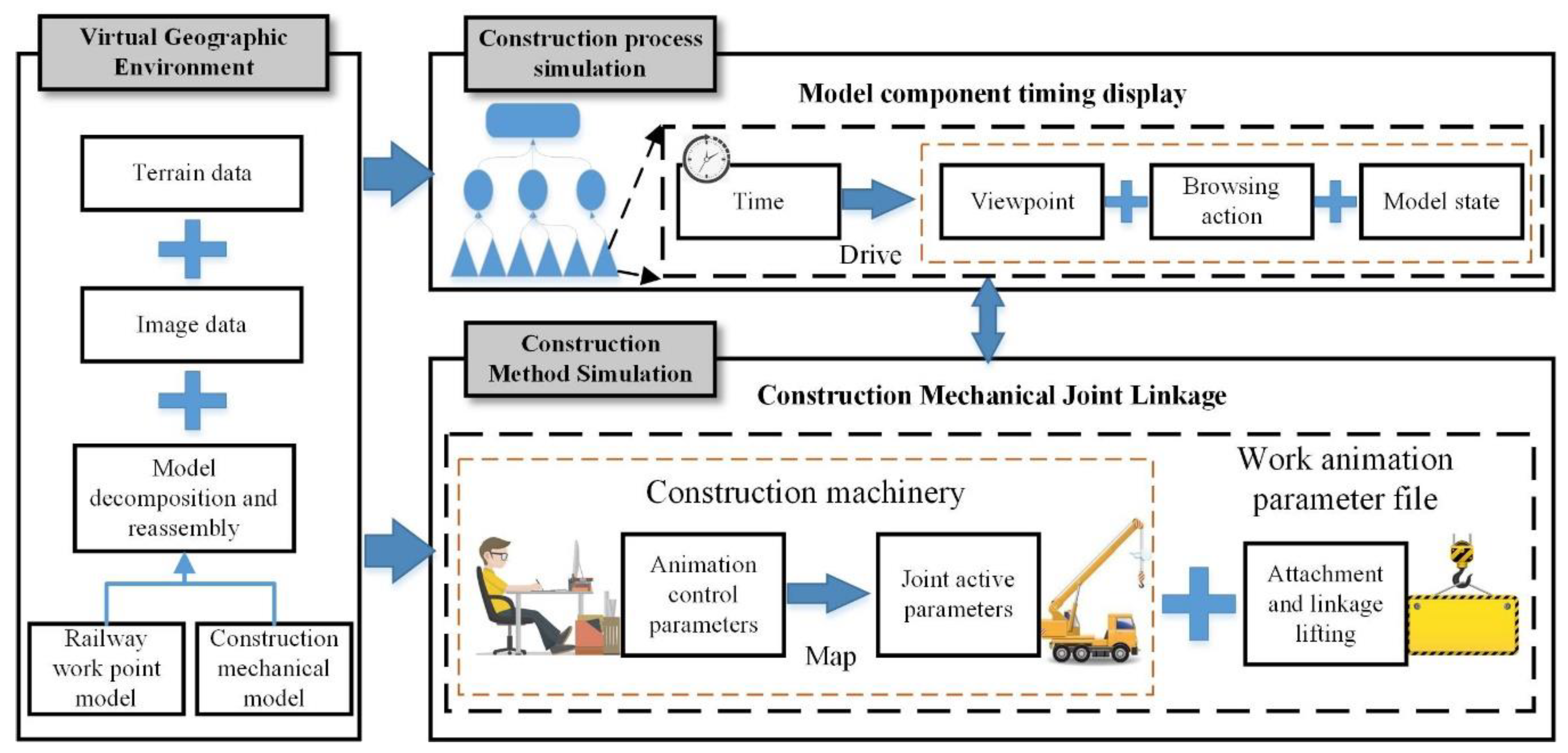
Figure 1 illustrates a dynamic construction simulation framework based on VGEs, a dynamic 3D spatial information system that provides at unified digital framework of the whole railway environment, which is represented by both macro geographic and geological environments and micro railway facilities; this framework mainly includes the following three key technical components.
(1) A high-precision VGE is generated based on model decomposition and reassembly. The VGE provides a basic display environment and an information-bearing framework for construction simulation, and it is formed from the fusion of multisource data, such as digital elevation model (DEM) data, digital orthophoto map (DOM) data, and three-dimensional model data. To dynamically simulate the construction process, a three-dimensional model must be decomposed according to the construction requirements, and then the decomposed model is reassembled in a virtual geographic scene. Models are organized and related in the scene based on semantic information. This process mainly includes the decomposition of railway work points and the construction of mechanical models. Model decomposition is the focus of process and engineering simulations.
(2) Model components are displayed in chronological order for construction process simulation. Process simulations roughly show the overall flow of construction at the macro level. All the construction processes are decomposed into a plurality of subprocesses, and each subprocess is further disassembled into a plurality of construction steps. Each subprocess corresponds to a playlist, and each construction step corresponds to a key frame in the three-dimensional scene. In the playlist, the viewpoint parameters, the action parameters, and the model parameters are driven by time parameters so that the actions are shown sequentially in time. At this point, the simulation of construction processes is complete.
(3) The construction method is simulated based on the joint linkage of construction machinery. A simulation is used to represent the construction method for local and complex work points. According to the construction method, local and complex work points are specifically displayed, and the user-oriented animation control parameters are mapped to mechanical joint activity parameters so that the operation of the construction machinery is effectively simulated. Moreover, the lifting object attachment parameters are added, and a work animation parameter file is jointly formed. At this point, the simulation of the construction method is complete. In addition, a work process simulation with a partial set of work points is usually integrated into the simulation process, and the methods are combined to complete the entire construction simulation process.

2.2. Virtual Geo-Environment Generation Based on Model Decomposition and Reassembly

2.2.1. Model Component-Level Decomposition

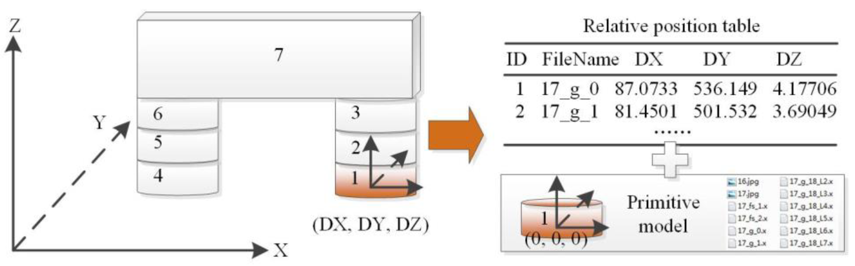
To simulate the construction process, the railway work point models and construction mechanical models need to be broken down into components and reassembled. This process mainly includes decomposition. Then, reassembly can be completed only by determining the adhesion relations among components. The railway engineering point model needs to recalculate the position information for each component after decomposition to perform reassembly in a three-dimensional scene.
As shown in Figure 2, each model is traversed, and each leaf node element in the model can be extracted as a model component object. Every model component should be stored as a single file and has a unique coordinate system, and the transfer variables are recorded in the transfer table. In this approach, the decomposed model file can be repositioned and reassembled according to the construction process in three-dimensional platform software. Thus, component-level model management and display control can be achieved.

2.2.2. Model Reassembly

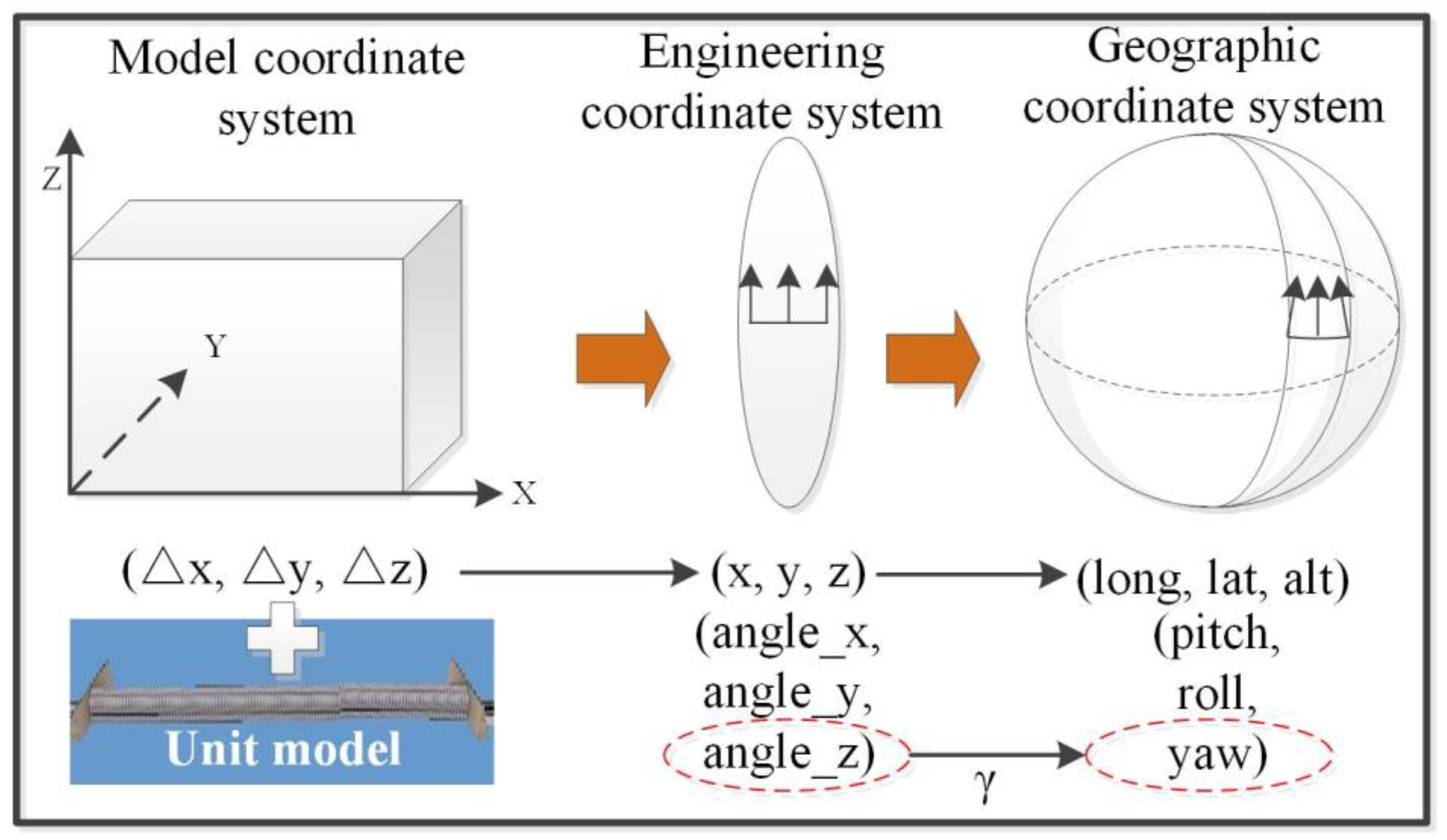
When the component model is reassembled and derived, the relative position relations between the components and the model origin under the model coordinate system are required. To achieve accurate positioning, the insertion point coordinates and attitude parameters of the model need to be specified in a three-dimensional scene. Therefore, the relative coordinates in the model coordinate system need to be converted into absolute coordinates in the spatial coordinate system. The main steps of coordinate system conversion are shown in the Figure 3, and the specific description is as follows.
(1) Model coordinate system to engineering coordinate system. Using the engineering coordinate system from the railway design and construction phase, the position and attitude of the body model in the engineering coordinate system can be obtained from the line design data and model geometry [27,30,31,32]. According to the position and posture information associated with the body model in the engineering coordinate system and the relative position data in the assembled relation table, the reassembly coordinates of the subcomponents in the engineering coordinate system can be obtained through position translation and attitude rotation.
(2) Engineering coordinate system to geographic coordinate system. The engineering coordinate system is typically a plane rectangular coordinate system after projection, and a geographic coordinate system needs to be used to display a railway three-dimensional scene that is long and has a large span. Reassembling the model in different projected coordinate systems requires calculating the model position, reprojecting, and calculating the projected azimuth correction value, that is, the meridian convergence angle correction. Notably, a Gaussian projection is for a vector, and components farther away from the central meridian show greater azimuth deviation. The calculation method for the approximation of the deviation angle correction value is shown in Formula (1).
γ = Δ L × s i n B
where γ is the meridian convergence angle correction value, ΔL is the longitudinal difference between the coordinate position point and the central meridian, and B is the latitude of the position.
In railway engineering, where the height difference is not large, the engineering coordinate system range is generally less than 40 km and the azimuth deviation is less than 0.2 degrees.

2.2.3. Virtual Geographic Environment Generation

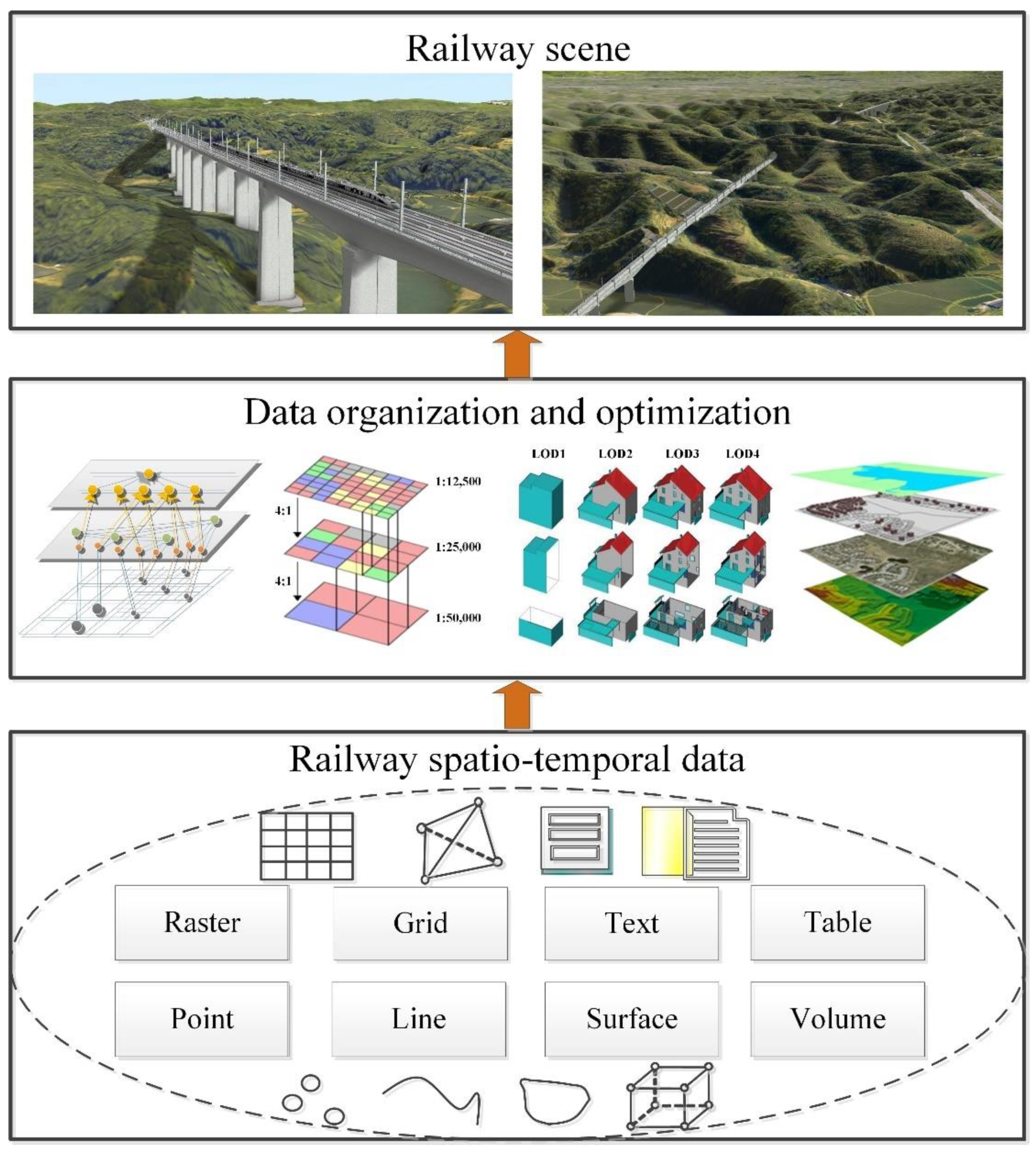
Figure 4 illustrates the generation process of a railway VGE, including multimodal spatio-temporal data fusion, data organization, and optimization. Since the construction methods of railway three-dimensional scenes are relatively mature [12,36,37,38,39], only a brief description is given here.
(1) Multimodal spatio-temporal data fusion. A railway three-dimensional scene mainly involves multisource heterogeneous data, such as DEM, DOM, three-dimensional model, line vector, text annotation, and attribute table data. Since a railway line is strip shaped, the terrain and features along the railway line use high-resolution data, and low-resolution data are used when the railway line is far away. The low-resolution below 1 m DOM uses satellite images, the high-resolution above 0.5 m DOM uses aviation photography images, the low-resolution below 20 m DEM uses shuttle radar topography mission (SRTM) data, and the high-resolution below 0.5 m DEM uses lidar data. To demonstrate the construction process, it is necessary to split the corresponding three-dimensional model, such as a body model (e.g., for a bridge) or mechanical model (e.g., for a tower crane), into many subcomponents. The line vector data record mileage information and can be used for rapid positioning according to the mileage data. The character annotations can be used to mark information in the three-dimensional scene, and the actions in the construction simulation process can be prompted. The attribute data record the model name, ID, spatial position, spatial pose, zoom, and other information.
(2) Data organization and optimization. The three-dimensional scene data are multisource and multi-format data in large data sets, and the data need to be organized and optimized to improve the efficiency of data browsing and access. The DEM and DOM are organized in a tiled way and managed in layers. The three-dimensional model can be optimized by setting a maximum visible distance, a minimum visible distance, levels of detail (LOD), and other parameters. The three-dimensional models are organized and related in the scene based on semantic information which is extended and defined based on the international framework for dictionaries (IFD) standard issued by the buildingSMART organization. Semantic information is described, stored, and exchanged through metadata. Considering the decomposition of the three-dimensional model of a construction site, the body model is managed as a parent node, and each component model is managed as a child node in a three-dimensional scene.
(3) Virtual geographic environment generation. The multimodal spatio-temporal data are unified to the same spatio-temporal reference, and the railway three-dimensional scene is generated. The three-dimensional model is loaded into the scene in the form of three-dimensional point symbols.

2.3. Construction Process Simulation Based on Model Component Timing Display

High-speed railway construction technologies and methods are complicated. Three-dimensional models are disassembled into small parts, and the processes used to display and hide small parts are controlled according to different time points, durations, and other time information, thus simulating the construction process, that is, a construction process simulation based on the time series display of the model parts.

2.3.1. Construction Process Decomposition

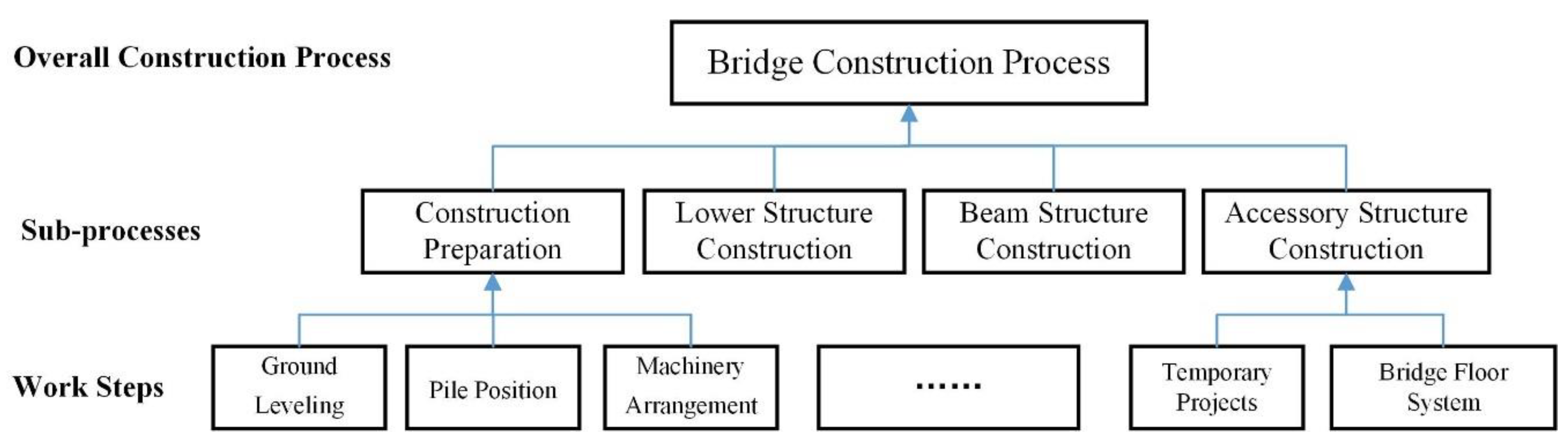
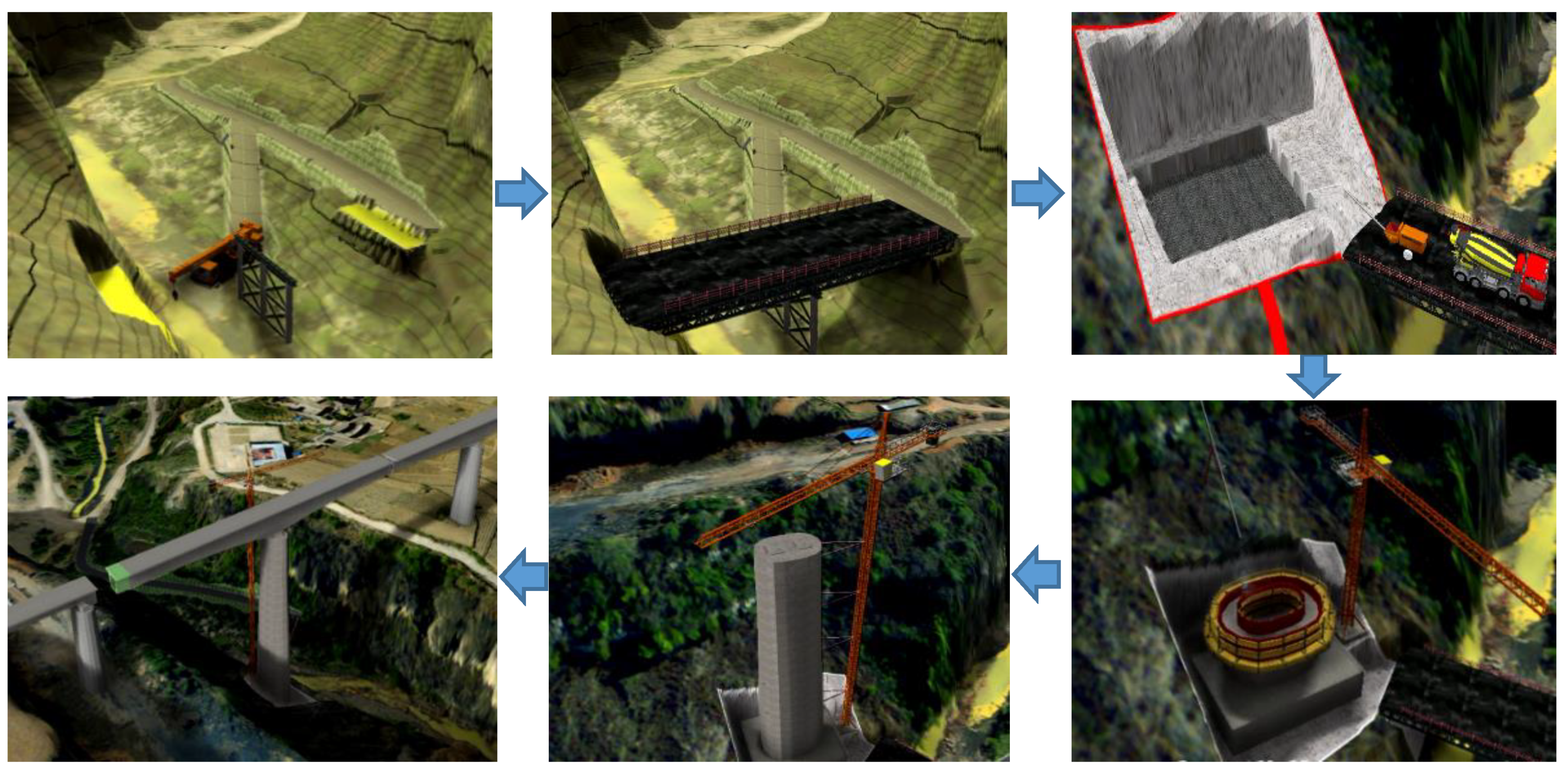
In the construction process simulation, the overall construction process is split from top to bottom, and decomposed into several subprocesses; then, each subprocess is further divided until each detailed action is split. In this context, the entire process of bridge construction can be decomposed into four parts: construction preparation, lower structure construction, beam structure construction, and accessory structure construction, as shown in Figure 5. Each part can be further divided into a number of construction work steps, and each work step ultimately corresponds to a frame image in the three-dimensional scene. For example, the construction preparation stage can be further divided into ground levelling, pile positioning, machinery arrangement, and other tasks.

2.3.2. Construction Process Simulation

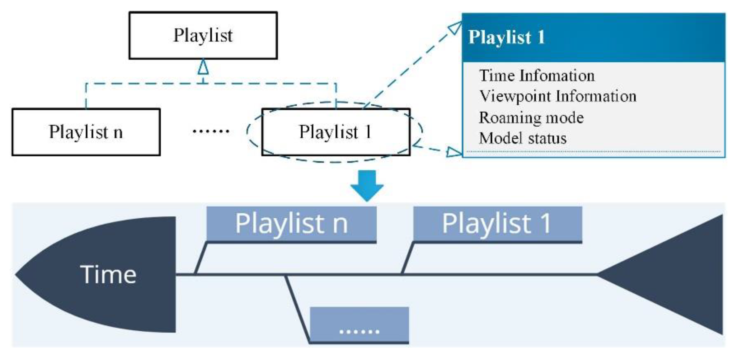
Each construction process is stored with a playlist. Because playlists can be nested, subprocesses can also be stored in playlists. Time information, viewpoint information, browsing actions, and model states are stored in the sub-playlists. The time information is the most important information because it influences the duration of a certain action at a certain point in time. Potential actions could include moving the viewpoint, displaying and hiding parts of the model. The information in the playlist is sequentially processed according to the time information, and the subprocesses are implemented. When all sublists have been addressed, the overall process simulation is formed, as shown in Figure 6.

2.4. Construction Method Simulation Based on Mechanical Joint Linkage

Most construction methods require special construction machinery. The animated simulation of construction machinery is an advanced expression of virtual construction, and the complete construction process can be simulated directly to identify construction difficulties and priorities. Mechanical simulations of construction processes involve complex mechanical joint control and linkage strategies, the transfer relationships among types of machinery, materials, and the surrounding environment, and the spatial relationships among construction machinery. A joint linkage involves two or more independent joints that are simultaneously active in different planes to co-complete an action. Through the relative positioning of model components (associated with a parent), after multilevel coordinate conversion, the position and attitude parameters of the component model in the three-dimensional scene can be obtained, and component positioning and assembly can be achieved. Since the joints are adjacent to each other, when creating a joint animation, the relative relationship between the component and the parent may be considered only with respect to the method of relative positioning. The following steps are used in construction simulations based on joint linkages.

2.4.1. Extraction of Mechanical Joint Activity Parameters

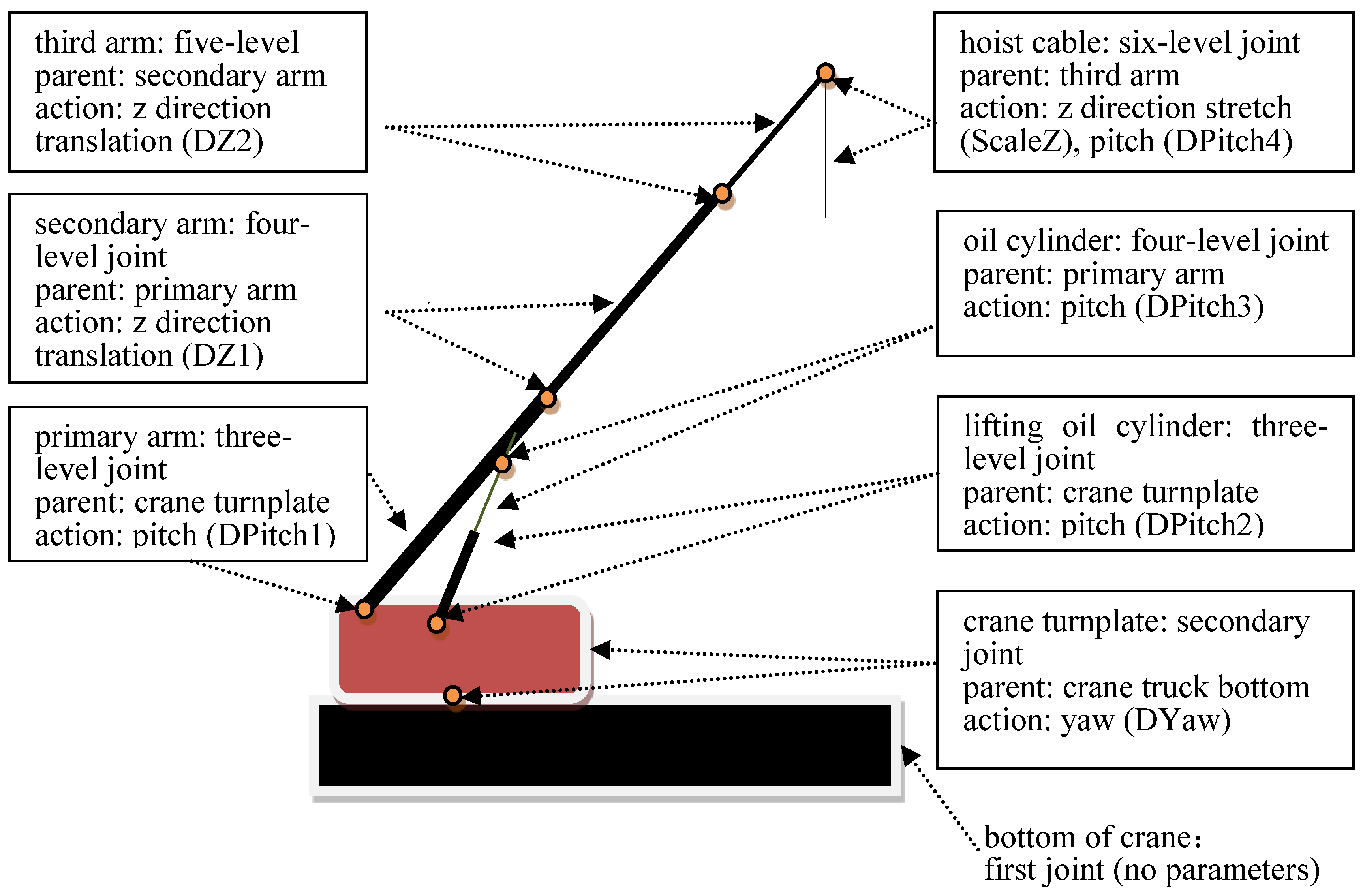
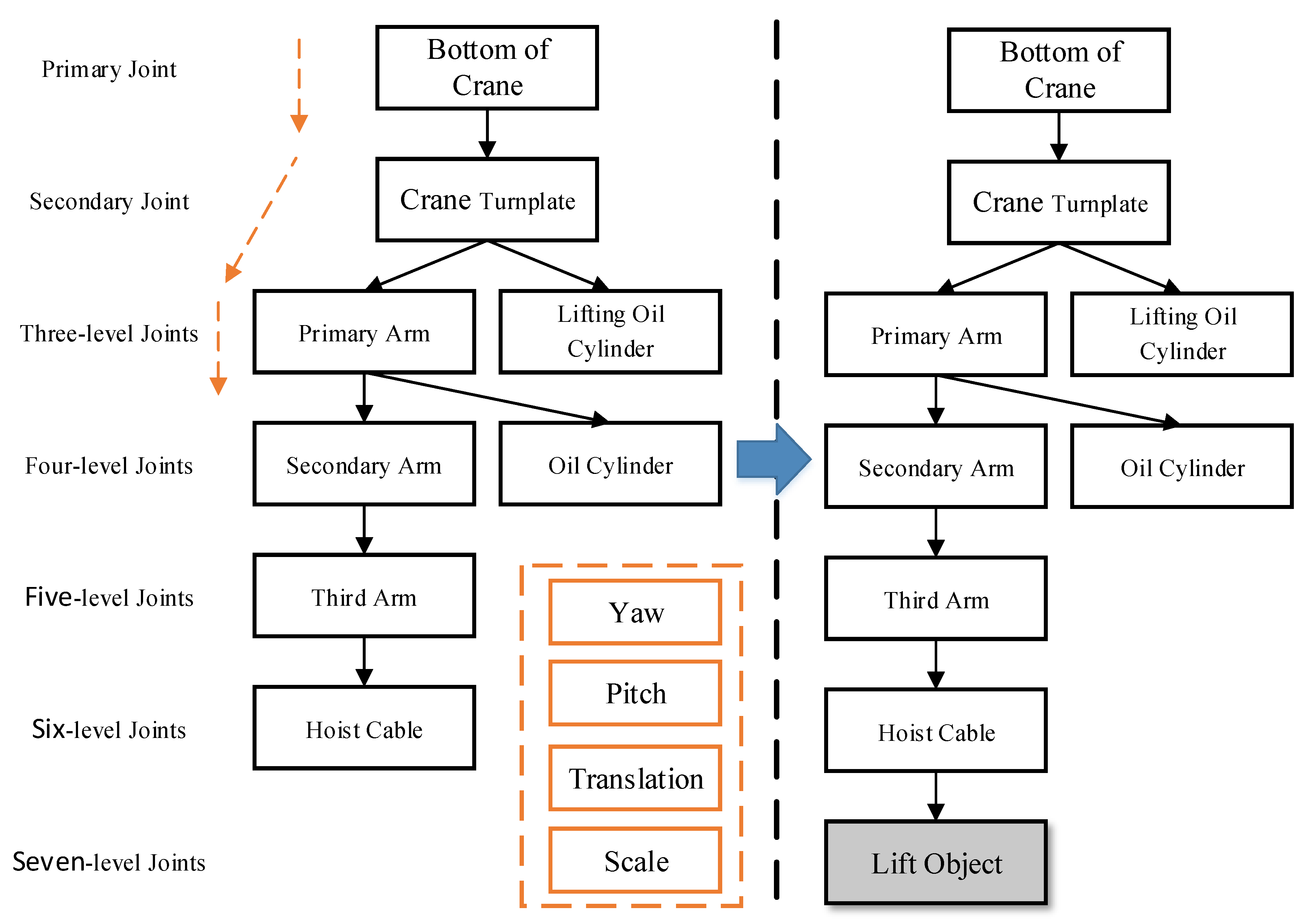
Although construction machinery works in a variety of ways, the movement of each joint is fixed. According to the operation actions of construction machinery, the corresponding model can be decomposed according to the joints, and the action of each joint is determined to provide a foundation for the extraction of mechanical work parameters. The joint splitting of the crane model considering joint activities yields the bottom of the crane (no action), crane turnplate (yaw), first arm (pitch), secondary arm (z-direction translation), third arm (z-direction translation), hoist cable (z-direction stretching and pitch), and oil cylinder (pitch). The bottom of the crane moves with the crane, so it is free of internal parameters. The crane turnplate mainly rotates in the horizontal direction around the bottom of the crane and therefore has a translational parameter.
After the model joints are decomposed, the level of each joint, namely, the mutual adhesion relation associated with two joints, needs to be determined according to the linkage relations in the model. Since the other joints are used as a final reference at the bottom of the crane, the bottom of the crane is a primary joint. The crane turnplate is attached to the bottom of the crane and is a secondary joint. The primary arm and the lifting oil cylinder are both attached to the crane turnplate and are tertiary joints. The secondary arm and the oil cylinder are fourth-level joints that are attached below the primary arm. The third arm is a fifth-level joint that is attached to the secondary arm. The hoist cable is a sixth-level joint that is attached to the third arm. The disassembly of the model joints, the action of each joint, and the linkages among joints are shown in Figure 7.
The simulation mathematical model for the working state of a crane is as follows:
M ( R ,   L , S , H ) = [ R ( dYaw ) ,   L ( d P i t c h 1 ,   d P i t c h 2 ,   d P i t c h 3 ,   d P i t c h 4 ) ,   S ( d Z 1 , d Z 2   ,   d Z n ) ,   H ( d Z S c a l e , d Z ) ]
R ( d Y a w ) = d Y a w
L ( d P i t c h 1 , d P i t c h 2 , d P i t c h 3 , d P i t c h 4 ) = { d P i t c h 2 = a r c t a n ( s i n ( d P i t c h 1 ) × L c o s ( d P i t c h 1 ) × L L A B ) d P i t c h 3 = d P i t c h 2 180 d P i t c h 4 = d P i t c h 1
S ( d Z 1 , d Z 2 ,   d Z n ) = L + 1 n d Z n
H ( d Z S c a l e , d Z ) = { L C = L O C × d Z S c a l e d Z = L C
where   R ( d Y a w ) is the lifting rotation state function; d Y a w is a rotary yaw angle; L ( d P i t c h 1 ,   d P i t c h 2 ,   d P i t c h 3 ,   d P i t c h 4 ) is the lifting state function of the lifting arm; d P i t c h 1 is the pitch angle of the lifting arm; d P i t c h 2 is the pitch angle of the oil cylinder body; d P i t c h 3 is the pitch angle of the lifting oil cylinder; d P i t c h 4 is the pitch angle of the hoist cable; L is the length of the first arm; L A B is the length between the first arm and lifting arm;
S ( d Z 1 , d Z 2 ,   d Z n ) is the stretching state function of the arm; d Z n is the z-direction offset distance of the nth section of the arm;
H ( d Z S c a l e , d Z ) is the stretch state function of the hoist cable; d Z S c a l e is the z-direction stretching ratio of the hoist cable; d Z is the z-direction offset distance of the hoist cable;   L O C is the original length of the hoist cable; and L C is the stretching length of the hoist cable.

2.4.2. User-Oriented Animation Control Parameters

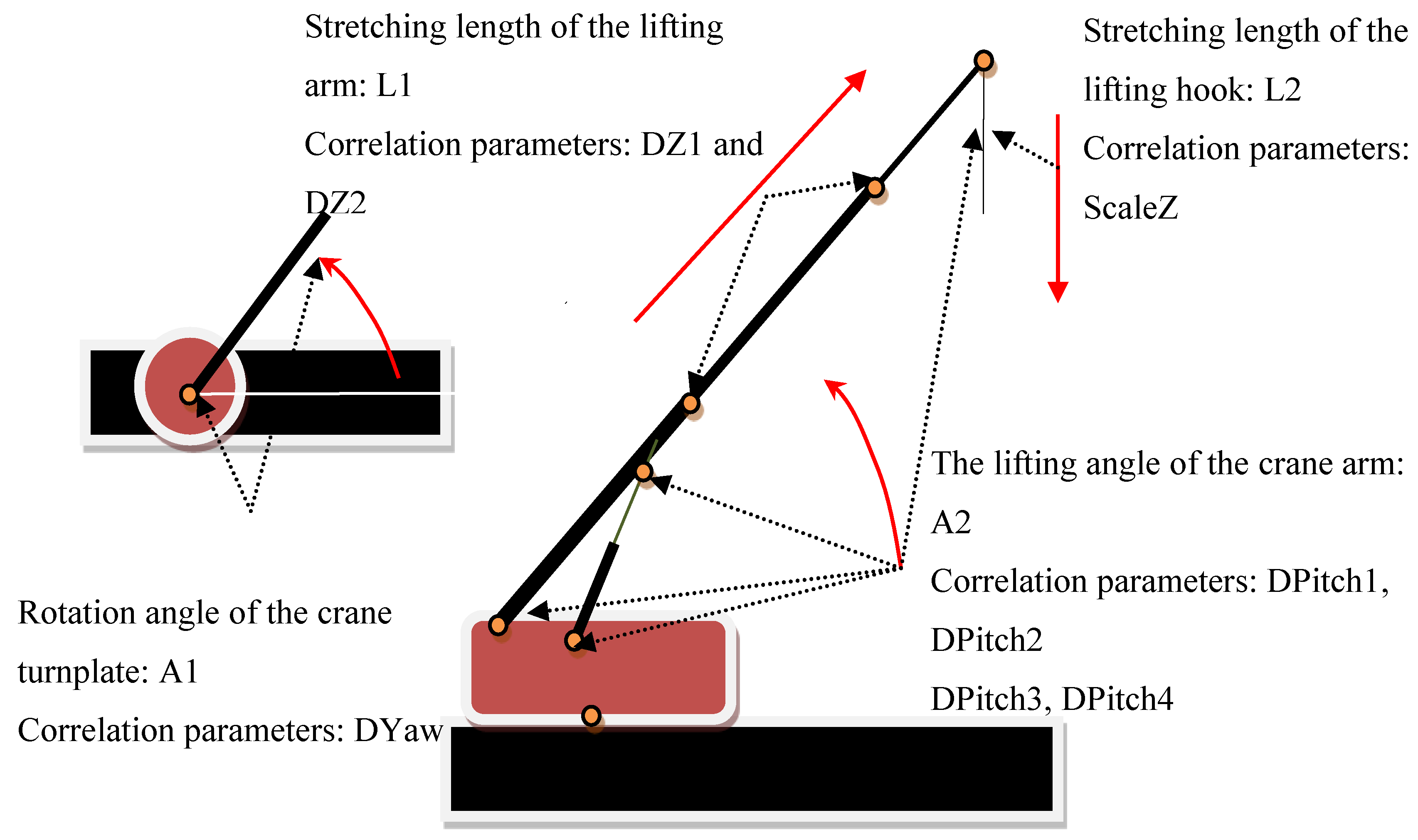
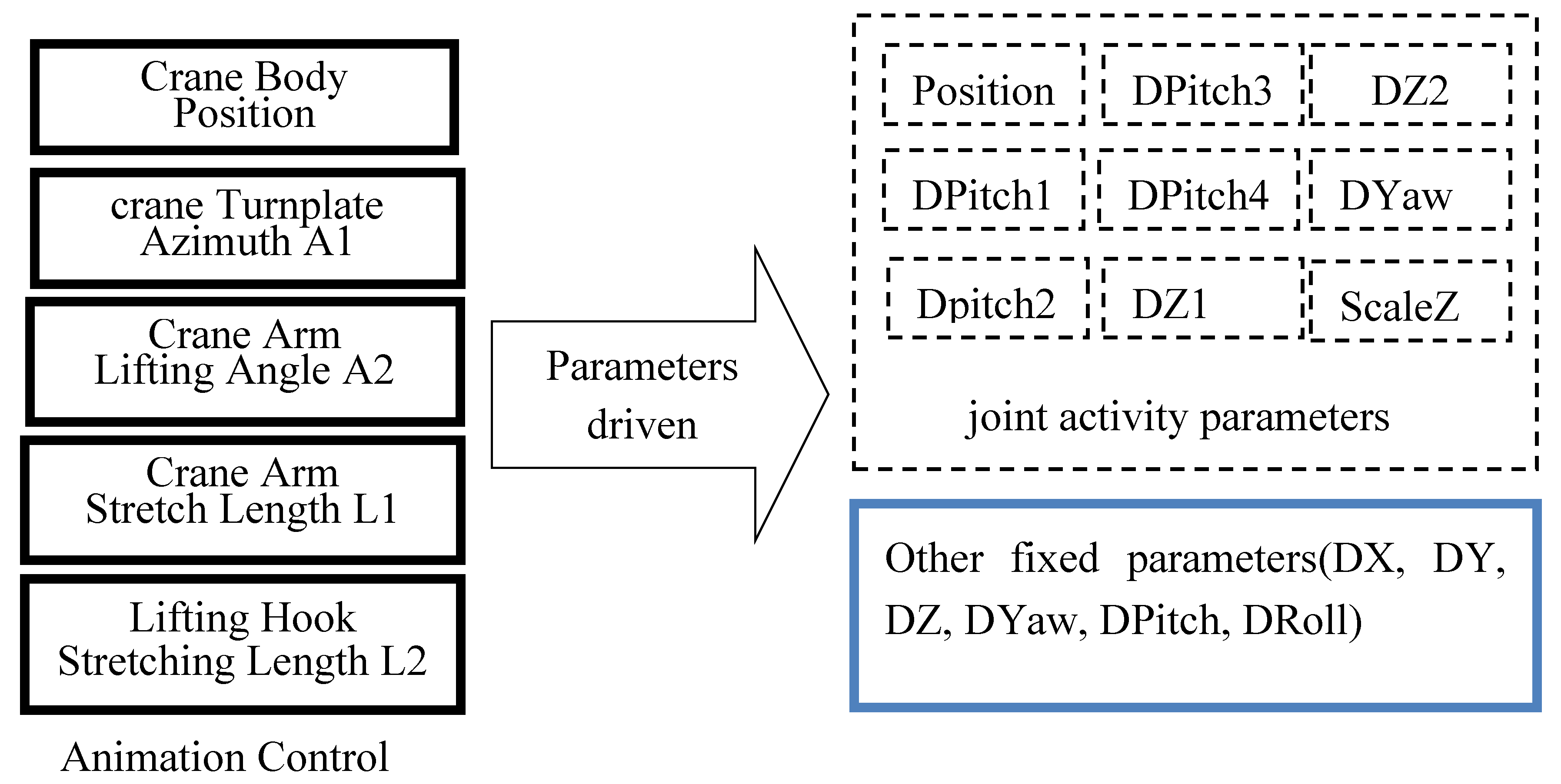
In order to control the mechanical motion, the following four animation control parameters are abstracted and then can be modified interactively as shown in Figure 8: A1, the rotation angle of the crane turnplate, which influences the plane rotation parameter DYaw of the crane turnplate;
A2, the lifting angle of the crane arm, which influences the pitch angle of the primary arm, the lifting oil cylinder, the oil cylinder and the hoist cable;
L1, the stretching length of the lifting arm, which influences the stretching lengths of the secondary arm DZ1 and the third arm DZ2;
L2, the stretching length of the lifting hook, which influences the vertical-direction stretching parameter ScaleZ.

2.4.3. Mapping of Animation Control Parameters to Joint Activity Parameters

Animation control parameters are oriented to the user for the control of virtual construction, and the joint activity parameters are used in the construction simulation to calculate the position and attitude of each joint. Thus, there is a need to establish mapping relationships for the animation control parameters to the joint activity parameters. The repositioning and assembly of the component model are performed in real time according to the joint parameters so that any control of mechanical animation based on the packaging parameters can be achieved, as shown in Figure 9.

2.4.4. Attachment for Hoisting

After the joint actions of the construction machinery are simulated, it is necessary to simulate the action when the construction machinery lifts an object. The object is hoisted based on the movement of the machinery; for example, the object rotates with the rotation of the arm. As a result, the hoisted object needs to be attached to the construction machinery. When analysing the joint linkage relationships of the crane, the hoist cable is a sixth-level joint. When the crane is lifting, the object being hoisted needs to be attached to the hoist cable and becomes a seventh-level joint. Figure 10 illustrates the joint linkage relationships after the object to be hoisted is attached to the crane. In the figure, the dashed lines represent the transfer of linkage relationships, i.e., the child joints will move with the movement of the parent joints, with the movements mainly including rolling, rotation, translation, and stretching.

2.4.5. Work Animation Parameter Storage

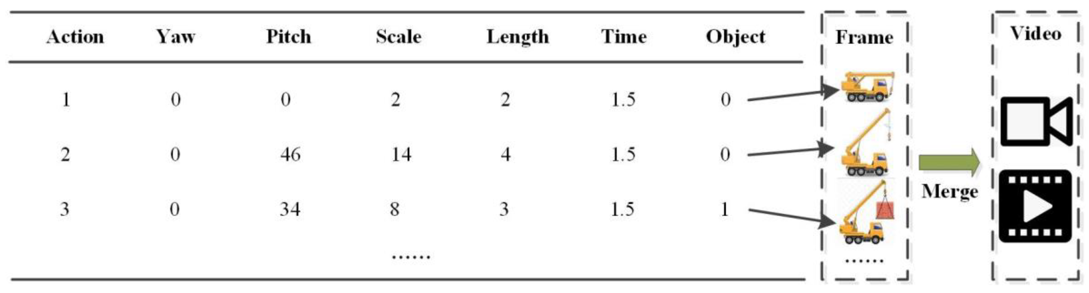
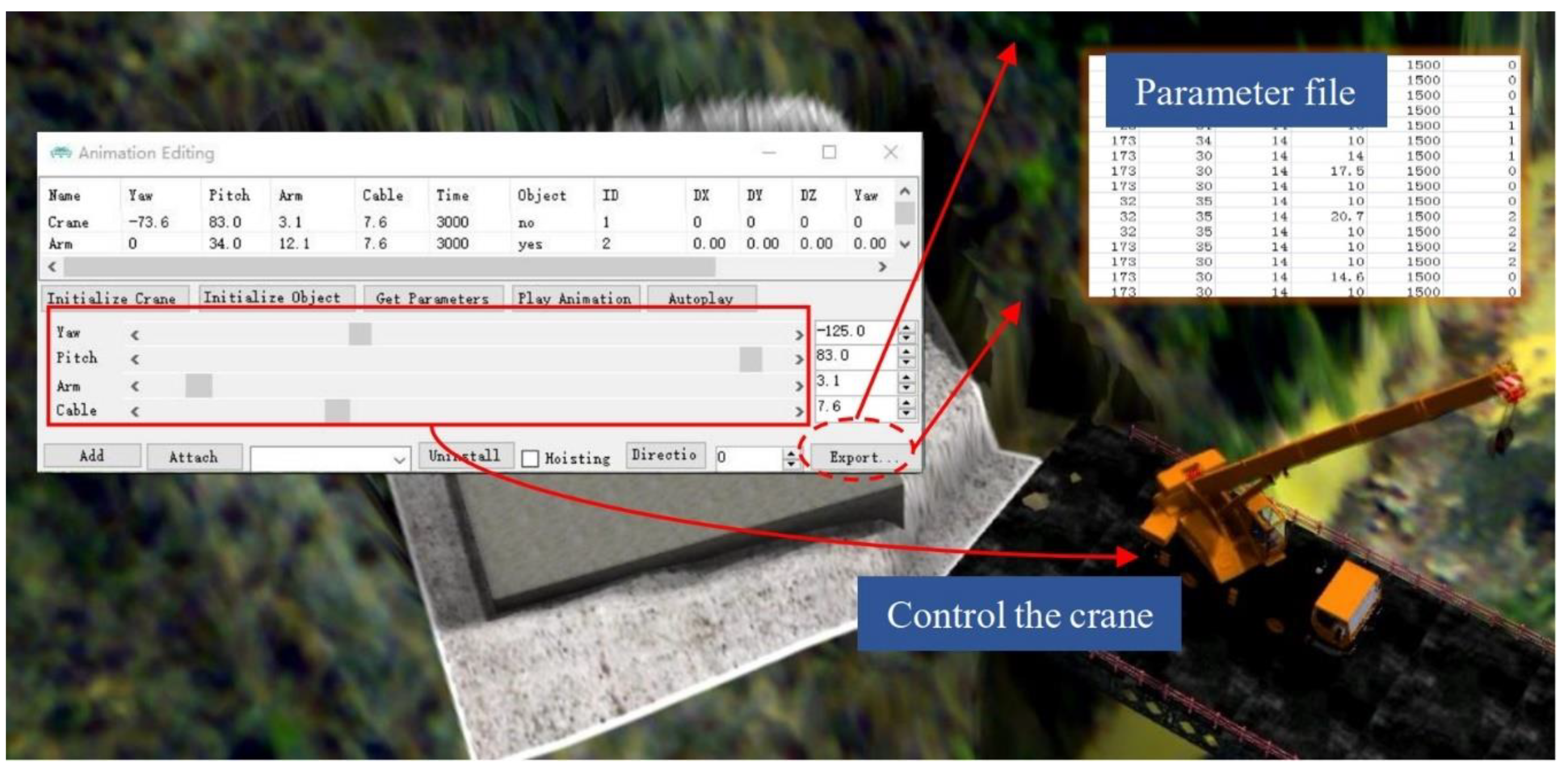
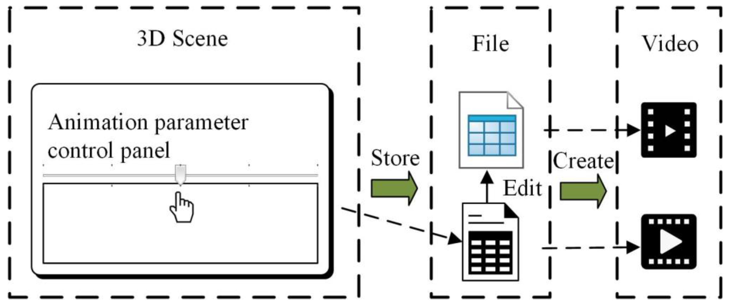
To save the work animation of construction machinery in a three-dimensional scene, an external parameter script file is used. The parameter script file records the parameter information for the construction machinery in a key operation step, including the yaw, pitch, scale, length, duration, number, etc., and linear interpolation is performed on the motion between the two moments to achieve a smooth transition between actions and obtain an animation. The yaw refers to the azimuth angle of the crane turntable, pitch refers to the arm lifting angle, scale refers to the arm stretching length, length refers to the hoist cable length, duration refers to the time required for the transition between two actions or points in time, and number is the ID of the hoisted object. Figure 11 illustrates an animation parameter script file, wherein each row of data corresponds to a key frame in a three-dimensional scene. A user can perform a variety of construction operation animation simulations by editing the parameter scripts or real-time control parameters. Based on the principle of parameter-driven mechanical animation and the related computing tools, the animation script of a continuous operation can be edited by recording the state parameters of the machinery. Then, the complex animation can be edited and played for different states through the smooth transition of parameters.

3. Experimental Analysis

3.1. Test Area Description

The construction of a high pier and the steep slope of a bridge on a high-speed railway line in Shanxi Province, China are simulated based on a VGE. The bridge adopts a (60 + 100 + 60) m continuous beam that spans a main river channel, and a hanging basket cantilever casting method is adopted for construction. The 19th pier is located on a (60 + 100 + 60) m continuous beam brake pier that spans a river, and the foundation is on limestone rock of pressure on a dug foundation. The base thickness is 7.5 m, and the pier has a round-end hollow-type structure. The height of the pier is 61.5 m. Due to the large span of continuous beams, a well-digging foundation is adopted; therefore, the requirements for linear control and construction imbalance are very high. In addition, the 19th pier is close to the river side, the foundation top is higher than the designed water level of 8.2 m, the surrounding environment has a high and steep slope more than 40 m above the top of the foundation, and the slope is close to 45 degrees. The construction site is too narrow, and the construction environment is so complicated that the construction process has to be fully simulated beforehand in a dynamic three-dimensional scene.
Bridge construction site environment modelling is based on the fusion of multisource data, such as satellite images, oblique photography, and laser radar data. According to the construction method and the construction performance requirements, the splitting and modelling schemes for the engineering body and related auxiliary objects are determined. After all kinds of objects are modelled, models are positioned and integrated according to the relative spatial relations of various objects in the construction process. There are two methods for model positioning: absolute positioning and relative positioning. The absolute positioning method is used for calculating the placement coordinates and the attitude of the model in the scene coordinate system and directly positioning the model. The relative positioning method is based on another model that has completed the absolute positioning process as the parent, the position offset and the attitude offset of the model relative to the parent are calculated; in this case, the positioning model is converted through these relative relationships. Figure 12 illustrates a three-dimensional scene of a construction site.
According to the mathematical model of the mechanical joint linkage relationships, a parameter control panel for crane operation animation is developed based on a three-dimensional platform so that the work state of the construction machinery is facilitated by interactive operations and simulations in a three-dimensional scene, as shown in Figure 13. The user can flexibly modify the animation control parameters through the panel, and based on the mapping relations between the animation control parameters and the joint activity parameters, the assembly relations among the components of the crane can be determined in real time; therefore, the dynamic operation of the crane is driven by the various parameters. In addition, the control panel may also record data for critical steps in crane operation, and these data can be used to generate key frames. Moreover, a mechanical work animation parameter file can be created by exporting the parameters and data for all key steps. When the parameter file is read again, the motion parameters between the key operation steps are interpolated so that a continuous operation animation of the construction machinery can be obtained.

3.2. Construction Simulation

3.2.1. Tower Crane Operation Simulation and Layout Scheme

It is necessary to troubleshoot the relevant safety hazards during tower crane layout and operation in advance because the example construction site is steep and narrow. Therefore, the dynamic spatial relationships involving the tower crane, the surrounding environment, and other construction machinery must be simulated and analysed. To determine whether tower crane operations at different heights will collide with the terrain, the tower crane model is decomposed into a plurality of tower crane assemblies and reassembled through model decomposition and assembly, as shown in Figure 14. Before the operation range of the tower crane is simulated, an attachment relation between the front and rear cantilever arms of the tower crane needs to be established to ensure a sufficient spatial linkage relationship between the cantilever arms, and the operation range of the tower crane is analysed by rotating the cantilever.
Figure 15 illustrates several aspects of tower crane routing. Scheme 1 shows the scheme of initializing the tower crane with four segments. Since the working range of the tower crane does not meet the self-hoisting requirement, a subsequent section cannot be hoisted from the stool bridge. Scheme 2 shows the scheme of initializing the tower crane with five segments. Because the tower crane is raised, the chance of collision with steep slopes is reduced, and the working range of the tower crane meets the relevant requirements. However, in this case, the working range of the crane is close to the limit, and the installation process cannot be completed by the crane. Finally, Scheme 3 adopts a four-segment initial tower crane and the side slope of the tower crane is excavated so that the working range requirement of the tower crane and space requirement for the crane and the hoist can be met.

3.2.2. Dynamic Crane Operation Simulation and Tower Crane Layout Simulation

Crane operation simulations involve complex mechanical joint control and linkages, as well as mechanical and material transfer relationships. By controlling the azimuth angle of the turntable, the lifting angle of the arm, the stretching length of the arm, the lifting length of the hoisting cable and other factors, the flexible operation of the construction machinery can be achieved. By attaching an object to the hoisting cable, a linkage between the object and the hoisting cable is achieved, and the construction machinery operation process can be flexibly simulated. After the tower crane initialization scheme is determined, the installation process needs to be simulated in a three-dimensional scene for further troubleshooting.
After the tower crane initialization scheme is determined, the installation process needs to be simulated in a three-dimensional scene to further assess the operation potential. Figure 16 illustrates the process of installing the tower crane of the 19th pier using a crane during construction. Through the process of rotating the crane base, stretching the arm, hoisting the hoisting cable and other steps, section assembly and large-cantilever splicing are completed for the tower crane.

3.2.3. Storage and Replaying of Construction Method Simulations

In a VGE, the user can control the crane operation in real time by adjusting parameters via the crane parameter control panel. When a scheme is reported and researched, the operation process is often not required to be controlled in real time, and the designed construction method needs to be reproduced. Therefore, it is necessary to study the storage and reproduction methods of construction simulation processes.
The user records the state parameters of each key operation step through the crane parameter control panel, and the parameters are saved as an external parameter file for operation animation so that the crane operation process is stored. Different parameters can be flexibly set with the crane parameter control panel, and different parameter files can be generated. In addition, externally stored parameter files can also be manually modified. These different parameter files can be re-imported into the three-dimensional scene and analysed, and different construction processes can be reproduced in the form of animations. Finally, the construction simulation process can be stored in the form of an external parameter file. Figure 17 illustrates the storage and reproduction processes of a construction method simulation.

3.2.4. Simulation of the Integral Construction Process for a Bridge

Construction process simulation cans be expressed in three-dimensional geographic environments by using an engineering body model, engineering auxiliary model and construction machinery, and construction animations can be generated through a small number of key frames. After the engineering body model and the engineering auxiliary model are decomposed and reassembled, a time period for displaying or hiding each component is set, and the display or hidden state of the model is added to the key frame. In these key frames, the position and attitude of the viewpoint can also be recorded to better observe the construction process. Moreover, actions such as flight and roaming can also be inserted between the key frames so that the construction conditions associated with different positions can be browsed. Finally, the key frames are played in sequence over time, and the key frame animation performance of the process is assessed.
Figure 18 illustrates a bridge construction process in a three-dimensional scene that includes construction service roads, trestle construction, foundation pit filling, the construction platform layout, bridge pier construction, bridge beam construction, and closure. The construction service roads, the trestle and the foundation pit are simulated in engineering auxiliary models; the platform, the bridge pier, and the bridge beams are simulated in engineering body models; and all models and components are loaded into the three-dimensional scene in the form of graph layers. Construction process simulations provide a basis for construction machinery modelling and feasibility assessments of construction methods.

4. Conclusions

This paper introduces a dynamic 3D simulation method for complex high-speed railway engineering construction based on VGEs, and the following conclusions are summarized:
(1)
Multiscale representation of railway environments and dynamic 3D simulations of construction process are achieved, and they greatly improve the overall and local precise control of project management.
(2)
The operation mode of construction machinery is converted into mechanical movement parameters for machinery, and further abstracted into user-oriented animation control parameters, which can optimize the dynamic operation process of complex construction machinery.
(3)
Dynamic 3D simulations of complex multi-specialty construction processes in a wide geographic area are generated in VGEs and provide an effective method of optimizing construction plan designs, scientific management, hidden trouble investigations, accident rescue, etc. and also lays a foundation for the construction of digital twin railways.
Next, we will focus on expanding the construction machinery library, and develop a variety of mechanical operation and control methods to achieve multi-mechanical collaborative construction simulation.

Author Contributions

All of the authors contributed to the research concepts and participated in discussing and writing the manuscript. Qing Zhu, Xinwen Ning and Junxiao Zhang conceived and designed the case study. Xinwen Ning performed the experiments and wrote the paper. Changjin Wang, Zujie Han, Heng Zhang and Wen Zhao revised the paper. Zujie Han, Xinwen Ning, Wen Zhao and Heng Zhang prepared and tested the datasets. All authors have read and agreed to the published version of the manuscript.

Funding

This research was supported by the National Natural Science Foundation of China (Grant No. 41941019), National Natural Science Foundation of China (Grant No. 2016YFC0803105).

Conflicts of Interest

The authors declare no conflicts of interest.

References

  1. Kim, C.; Son, H.; Kim, C. Automated construction progress measurement using a 4D building information model and 3D data. Automat. Constr. 2013, 31, 75–82. [Google Scholar] [CrossRef]
  2. Azhar, S.; Nadeem, A.; Mok, J.Y.; Leung, B.H. Building Information Modeling (BIM). A new paradigm for visual interactive modeling and simulation for construction projects. In Proceedings of the First International Conference on Construction in Developing Countries, Karachi, Pakistan, 4–5 August 2008; Volume 1, pp. 435–446. [Google Scholar]
  3. Song, S.; Yang, J.; Kim, N. Development of a BIM-based structural framework optimization and simulation system for building construction. Comput. Ind. 2012, 63, 895–912. [Google Scholar] [CrossRef]
  4. Wang, W.; Weng, S.; Wang, S.; Chen, S. Integrating building information models with construction process simulations for project scheduling support. Automat. Constr. 2014, 37, 68–80. [Google Scholar] [CrossRef]
  5. Li, Y.; Liu, C. Integrating field data and 3D simulation for tower crane activity monitoring and alarming. Automat. Constr. 2012, 27, 111–119. [Google Scholar] [CrossRef]
  6. Boton, C. Supporting constructability analysis meetings with Immersive Virtual Reality-based collaborative BIM 4D simulation. Automat. Constr. 2018, 96, 1–15. [Google Scholar] [CrossRef]
  7. Ghawana, T.; Aleksandrov, M.; Zlatanova, S. 3D geospatial indoor navigation for disaster risk reduction and response in urban environment. ISPRS J. Photogramm. 2018, 4, 49–57. [Google Scholar] [CrossRef] [Green Version]
  8. Zlatanova, S.; Yan, J.; Wang, Y.; Diakité, A. Geo-Information Spaces in Spatial Science and Urban Applications-State of the Art Review. Int. J. Geo Inf. 2020, 9, 58. [Google Scholar] [CrossRef] [Green Version]
  9. Chen, M.; Lin, H.; Hu, M.; He, M.; He, L.; Zhang, C. Real-geographic-scenario-based virtual social environments: Integrating geography with social research. Environ. Plan. B 2013, 40, 1103–1121. [Google Scholar] [CrossRef]
  10. Chen, M.; Lin, H.; Kolditz, O.; Chen, C. Developing dynamic virtual geographic environments (VGEs) for geographic research. Environ. Earth 2015, 10, 6975–6980. [Google Scholar] [CrossRef] [Green Version]
  11. Lin, H.; Batty, M.; Jørgensen, S.E.; Fu, B.; Konečný, M.; Voinov, A.; Torrens, P.; Lu, G.; Zhu, A.; Gong, J.; et al. Virtual Environments Begin to Embrace Process-based Geographic Analysis. Trans. GIS 2015, 19, 493–498. [Google Scholar] [CrossRef]
  12. Lin, H.; Chen, M.; Lu, G.N.; Zhu, Q.; Gong, J.; You, X.; Wen, Y.; Xu, B.; Hu, M. Virtual Geographic Environments (VGEs), a new generation of geographic analysis tool. Earth Sci. Rev. 2013, 126, 74–84. [Google Scholar] [CrossRef] [Green Version]
  13. Lin, H.; Chen, M.; Lu, G. Virtual geographic environment, a workspace for computer-aided geographic experiments. Ann. Assoc. Am. Geogr. 2013, 103, 465–482. [Google Scholar] [CrossRef] [Green Version]
  14. Lin, H.; Zhu, Q. The Linguistic Characteristics of Virtual Geographic Environments. Int. J. Remote Sens. 2005, 9, 158–165. [Google Scholar]
  15. Zhu, Q. Technical Progress of three dimensional GIS. Geomat. World 2011, 9, 25–27. [Google Scholar]
  16. Zhu, Q. Full Three-Dimensional GIS and Its Key Roles in Smart City. Geoinf. Sci. 2014, 2, 151–157. [Google Scholar]
  17. Waly, A.; Thabet, W. A virtual construction environment for preconstruction planning. Automat. Constr. 2003, 12, 139–154. [Google Scholar] [CrossRef]
  18. Zhong, D.; Bi, L.; Yu, J.; Zhao, M. Robustness analysis of underground powerhouse construction simulation based on Markov Chain Monte Carlo method. Sci. China Technol. Sci. 2016, 59, 252–264. [Google Scholar] [CrossRef]
  19. Du, R.; Zhong, D.; Yu, J.; Tong, D.; Wu, B. Construction simulation for a core rockfill dam based on optimal construction stages and zones: Case study. J. Comput. Civil Eng. 2015, 30, 05015002. [Google Scholar] [CrossRef]
  20. Zhong, D.; Zhang, P.; Wu, K. Theory and practice of construction simulation for high rockfill dam. Sci. China Ser. E 2007, 50, 51–61. [Google Scholar] [CrossRef]
  21. Zhong, D.; Cui, B.; Liu, D.; Tong, D. Theoretical research on construction quality real-time monitoring and system integration of core rockfill dam. Sci. China Ser. E 2009, 52, 3406. [Google Scholar] [CrossRef]
  22. Zhong, D.; Hu, W.; Wu, B.; Li, Z.; Zhang, J. Dynamic time-cost-quality tradeoff of rockfill dam construction based on real-time monitoring. J. Zhejiang Univ. Sci. A 2017, 18, 1–19. [Google Scholar] [CrossRef]
  23. Khoury, H.; Kamat, V.; Ioannou, P. Evaluation of General-Purpose Construction Simulation and Visualization tools for Modeling and Animating AirSide Airport Operations. Simul. T Soc. Mod. Sim. 2007, 83, 663–679. [Google Scholar] [CrossRef]
  24. Shafahi, Y.; Bagherian, M. A Customized Particle Swarm Method to Solve Highway Alignment Optimization Problem. Comput. Aided Civ. Inf. 2013, 28, 52–67. [Google Scholar] [CrossRef]
  25. Pushak, Y.; Hare, W.; Lucet, Y. Multiple-Path Selection for new Highway Alignments using Discrete Algorithms. Eur. J. Oper. Res. 2015, 248, 415–427. [Google Scholar] [CrossRef] [Green Version]
  26. Park, J.; Lee, K.; Sim, S.; Jung, H.; Spencer, J. Traffic Safety Evaluation for Railway Bridges Using Expanded Multisensor Data Fusion. Comput. Aided Civ. Inf. 2016, 31, 749–760. [Google Scholar] [CrossRef]
  27. Li, W.; Pu, H.; Schonfeld, P.; Song, Z.; Zhang, H.; Wang, L.; Peng, L. A Method for Automatically Recreating the Horizontal Alignment Geometry of Existing Railways. Comput. Aided Civ. Inf. 2019, 34, 71–94. [Google Scholar] [CrossRef] [Green Version]
  28. Kljuno, E.; Williams, R. Vehicle simulation system, controls and virtual-reality-based dynamics simulation. J. Intell. Robot. Syst. 2008, 52, 79–99. [Google Scholar] [CrossRef]
  29. Bruner, M.; Rizzetto, L. Dynamic simulation of tram–train vehicles on railway track. WIT T Built Environ. 2008, 101, 491–501. [Google Scholar]
  30. Xie, X.; Tang, Z.; Jiang, J.; Zou, Y.; Ding, G. Design-Modal-Oriented Simulation for High-Speed Railyway Dynamics. Syst. Simul. 2018, 2, 465–472. [Google Scholar]
  31. Pu, H.; Zhang, H.; Li, W.; Xiong, J.; Hu, J.; Wang, J. Concurrent optimization of mountain railway alignment and station locations using a distance transform algorithm. Comput. Ind. Eng. 2019, 127, 1297–1314. [Google Scholar] [CrossRef]
  32. Li, W.; Pu, H.; Schonfeld, P.; Zhang, H.; Zheng, X. Methodology for optimizing constrained 3-dimensional railway alignments in mountainous terrain. Transp. Res C Emerg. Technol. 2016, 68, 549–565. [Google Scholar] [CrossRef] [Green Version]
  33. Li, W.; Pu, H.; Zhao, H.; Liu, W. Approach for Optimizing 3D Highway Alignments Based on Two-stage Dynamic Programming. J. Softw. 2013, 8, 2967–2973. [Google Scholar] [CrossRef]
  34. Lv, X.; Zhou, X. The motion simulation of high-speed train. J. Graph. 2013, 34, 87–91. [Google Scholar]
  35. Ding, G.; Jie, J.; Hai, Z.; Xiao, J.; Rong, L.; Yi, S.; Jian, Z. Development and Challenge of Digital Design of High-Speed Trains in China. J. Southwest Jiaotong Univ. 2016, 51, 251–263. [Google Scholar]
  36. Chen, M.; Lin, H.; Lu, G. Virtual geographic environments. In International Encyclopedia of Geography: People, the Earth, Environment and Technology: People, the Earth, Environment Technolog; Wiley: Hoboken, NJ, USA, 2016; pp. 1–11. [Google Scholar]
  37. Zhang, H.; Zhu, J.; Zhu, Q.; Qi, H.; Wang, C.; Han, Z.; Ning, X. A template-based knowledge reuse method for generating multitype 3D railway scenes. Int. J. Digit. Earth 2018, 11, 179–194. [Google Scholar] [CrossRef]
  38. Rink, K.; Nixdorf, E.; Zhou, C.; Hillmann, M.; Bilke, L. A Virtual Geographic Environment for Multi-Compartment Water and Solute Dynamics in Large Catchments. J. Hydrol. 2020, 124507, 238–253. [Google Scholar] [CrossRef]
  39. Mortari, F. Automatic Extraction of Improved Geometric Network Model from CityGML for Indoor Navigation. Master’s Thesis, TU Delft, Delft, The Nederland, 2013. [Google Scholar]
Figure 1. Dynamic construction simulation framework based on a virtual geographic environment.
Ijgi 09 00292 g001
Figure 2. Model decomposition and derivation.
Ijgi 09 00292 g002
Figure 3. Coordinate system conversion.
Ijgi 09 00292 g003
Figure 4. Railway virtual geographic environment generation.
Ijgi 09 00292 g004
Figure 5. Construction process decomposition.
Ijgi 09 00292 g005
Figure 6. Construction process simulation.
Ijgi 09 00292 g006
Figure 7. Linkage relationships among crane joints.
Ijgi 09 00292 g007
Figure 8. Animation control parameter extraction oriented to the user.
Ijgi 09 00292 g008
Figure 9. Mapping of animation control parameters to joint activity parameters.
Ijgi 09 00292 g009
Figure 10. Linkage relationships after crane attachment for lifting.
Ijgi 09 00292 g010
Figure 11. Parameter file generation for work animation.
Ijgi 09 00292 g011
Figure 12. Three-dimensional scene of a construction site.
Ijgi 09 00292 g012
Figure 13. Crane parameter control interface.
Ijgi 09 00292 g013
Figure 14. Section view of the tower crane: (a) four segments; (b) five segments.
Ijgi 09 00292 g014
Figure 15. Comparison of tower crane layout schemes.
Ijgi 09 00292 g015
Figure 16. Continuous animation of crane operation.
Ijgi 09 00292 g016
Figure 17. Storage and reproduction of construction method simulation.
Ijgi 09 00292 g017
Figure 18. Construction process simulation.
Ijgi 09 00292 g018

