Article

Mission Flight Planning of RPAS for Photogrammetric Studies in Complex Scenes

by
José Miguel Gómez-López
,
José Luis Pérez-García
,
Antonio Tomás Mozas-Calvache
* and
Jorge Delgado-García
Departamento de Ingeniería Cartográfica, Geodésica y Fotogrametría, Universidad de Jaén, Campus Las Lagunillas sn, 23071 Jaén, Spain
*
Author to whom correspondence should be addressed.
ISPRS Int. J. Geo-Inf. 2020, 9(6), 392; https://0-doi-org.brum.beds.ac.uk/10.3390/ijgi9060392
Submission received: 6 May 2020 / Revised: 8 June 2020 / Accepted: 14 June 2020 / Published: 16 June 2020
(This article belongs to the Special Issue Unmanned Aerial Systems and Geoinformatics)

Abstract

:
This study describes a new approach to Remotely Piloted Aerial Systems (RPAS) photogrammetric mission flight planning. In this context, we have identified different issues appearing in complex scenes or difficulties caused by the project requirements in order to establish those functions or tools useful for resolving them. This approach includes the improvement of some common photogrammetric flight operations and the proposal of new flight schemas for some scenarios and practical cases. Some examples of these specific schemas are the combined flight (which includes characteristics of a classical block flight and a corridor flight in only one mission) and a polygon extrusion mode to be used for buildings and vertical objects, according to the International Committee of Architectural Photogrammetry (CIPA) recommendations. In all cases, it is very important to allow a detailed control of the flight and image parameters, such as the ground sample distance (GSD) variation, scale, footprints, coverage, and overlaps, according to the Digital Elevation Models (DEMs) available for the area. In addition, the application could be useful for quality control of other flights (or flight planning). All these new functions and improvements have been implemented in a software developed in order to make RPAS photogrammetric mission planning easier. The inclusion of new flight typologies supposes a novelty with respect to other available applications. The application has been tested using several cases including different types of flights. The results obtained in the quality parameters of flights (coverage and GSD variation) have demonstrated the viability of our new approach in supporting other photogrammetric procedures.

Graphical Abstract

1. Introduction

The current use of aerial platforms based on Remotely Piloted Aerial Systems (RPAS) (also called Unmanned Aerial Systems (UAS) (To clarify, terms such as RPAS and UAS are used when referring to the complete system (aircraft and control system) and Unmanned Aerial Vehicle (UAV) or drones when referring to the aircraft exclusively.) has undergone a great development in photogrammetric applications [1,2,3,4,5,6]. These applications cover a wide range of scientific areas, from environmental to industrial and archaeological studies. In addition to this great variability among case studies, there is a great diversity of aerial systems with different features, which condition the type of flights that can be performed. For example, the system weight or Maximum Take-Off Weight (MTOW) constitutes an important aspect to be considered because it limits the study to be undertaken (payloads and sensors) and other characteristics such as time of flight (flight speed, distance and height, etc.). There are several classifications of RPAS proposed by several authors and institutions [7,8,9,10,11]. As an example, Gupta et al. [9] described a classification based on MTOW, endurance, altitude, operational area radios, purpose of use, etc. Other aspects commonly used to classify RPAS are the type of platforms (fixed-wing, rotatory-wing, blimps, and flapping-wing) and the flight control used (ground-control or remote piloting and semiautonomous and autonomous). Several studies [3,12] gave more detailed descriptions of these classifications and applications. Additionally, other authors [1,2,13] described several examples of the use of RPAS in photogrammetric studies. We must also consider that the use of RPAS is conditioned by the regulations established in each country. As an example, in Spain, the maximum MTOW without Aircraft Certification is 25 kg, the flight distance must be less than 500 m in Visual Line Of Sight (VLOS), Extended Visual Line Of Sight (EVLOS), or Beyond Visual Line Of Sight (BVLOS) modes, and the flight height is limited to 120 m (400 ft) [11]. A more detailed global database of the regulations of RPAS by county is shown in Global Drone Regulations Database [14]. Following these regulations, in this study, we consider RPAS of maximum MTOW of 25 kg, which are the systems most frequently used for these purposes.
Photogrammetric mission planning consists of the process of determining the location to fly over (waypoints) and the vehicle actions to perform (e.g., taking a picture) over a time period [15]. It is one of the first stages in a photogrammetric project workflow and is considered an important procedure because the image geometry has a strict relationship with the quality of the final products. For this task, we need to define the flight area (study zone), the RPAS characteristics (time of flight, speed, maximum height, and distance), the sensor to be used (resolution and focal length), and the orientation and positioning of the images to be acquired. Traditionally, photogrammetric mapping mission planning has been conditioned by the type of photogrammetric survey to be developed: conventional aerial photogrammetry, using conventional airplanes or helicopters, covering distances greater than 300 m, and close-range photogrammetry, using RPAS or terrestrial images for distances of less than 300 m [16]. These types of survey are described below:
  • Conventional aerial photogrammetry usually uses metric cameras mounted on planes assisted with high-quality positioning and orientation systems based on Global Navigation Satellite Systems (GNSS)/Inertial Navigation Systems (INS). In this case, the configuration of the flight is usually defined using flight lines or strips with predefined longitudinal and lateral overlaps. As examples, several studies [17,18,19] showed more detailed descriptions of the parameters to be considered and their calculation. The project requirements demanded by institutions or customers usually establish ranges of values for these parameters that must be taken into account in flight planning (overlaps, scale variability, etc.).
  • Close-range photogrammetry [20,21,22] supposes the acquisition of photographs at reduced distances to the object and combines stereoscopic normal case (parallel axes perpendicular to the object plane) with convergent images (convergent axes). This acquisition mode is the most widely used in terrestrial photogrammetry and in RPAS where weight-reduced and nonmetric cameras are widely employed. As an example, two studies [23,24] described the recommendations of the International Committee of Architectural Photogrammetry (CIPA), known as the 3 × 3 rules, for architectural photogrammetric projects planning using nonmetric cameras. In the geometric rules, it is recommended to use multiple photographic all-around coverage that includes taking a ring of images all around the object, overlapping each other by more than 50%, and taking normal stereoscopic images for 3D restitution.
The use of RPAS allows the combination of the two previously described methods because it allows the use of a wide range of scales and different geometries of capture (conventional aerial and close range). In addition, we must also consider the evolution of processing algorithms carried out in these photogrammetric projects. Recently, photogrammetric studies have undergone a great development caused by the appearance of applications based on algorithms such as Structure from Motion (SfM) [25,26,27]. This algorithm allows the orientation of photographs without knowing camera parameters and network geometry [28], given only a sparse set of correspondences between image features [29]. In fact, the orientation of photographs is based on the identification of some common feature point included in convergent photographs. Therefore, the SfM algorithm requires multiple and overlapping photographs located as convergent images [30].
Considering these methods and orientation algorithms, there are some aspects to be taken into account in mission planning such as:
  • In the normal case, the tendency is to use high overlaps (both longitudinal and lateral) because of the advantages in the photogrammetric processing (producing a more robust block from a geometric point of view that provides a best estimation of self-calibration parameters, and the reduction of occlusions, along with the possibility of selecting a central part of the images with less radial distortion and relief displacement). A typical feature, for instance, of mission plans for UAS photogrammetry is the large forward (80%) and cross (60–80%) overlap to compensate for aircraft instability [1]. In any case, a balance between the number of images and the cost of processing is desirable in any photogrammetric project.
  • In the case of SfM, there is the use of a large amount of convergent photographs that covers all objects redundantly from several points of view.
  • Variation of the distance to the object (height differences in vertical shots) can cause problems in stereoscopic coverage (normal case) or great differences in ground sample distance (GSD). This variation also impacts SfM because the features no longer match.
  • Displacement of the image during the capture: this issue is especially important when using cruising acquisition mode or fixed-wing RPAS.
  • The presence of obstacles and restricted areas.
  • The distance and height of the take-off point.
In addition to these aspects, we must consider other aspects such as those presented by Damilano et al. [31] who defined several optimization objectives according to some aspects such as minimum time, minimum distance, minimization of flight path changes, minimum risk considering given threats or obstacles, best range and endurance given available energy, best targets observation, and best data-link coverage. To date, several mission planning applications have been developed for RPAS. Pepe et al. [32] presented an overview of mission planning applications depending on the type of platforms and sensors. Gandor et al. [15] classified these applications into three categories: (i) proprietary and dedicated to a specific platform (e.g., Astec Navigator [33], MK-Tools [34], DroneDeploy [35], etc.); (ii) open-source applications (e.g., Mission Planner [36]); and (iii) those applications not dedicated to a specific platform (e.g., Universal Ground Control Station UgCS [37]). We consider an additional category that includes those noncommercial applications or uses for research purposes such as those presented by several authors [15,38,39,40,41] or the ones outlined in this study.
In this study, we analyze the main planning tools used by professionals and researchers by assessing their characteristics and applicability. In addition, we propose a new approach that integrates the advantages of these tools, considering particular issues useful for complex scenes that were not covered in existing applications. We consider those complex scenes where the use of ideal case of photogrammetry is not possible and it is difficult to guarantee a mean scale and GSD without great variations. The implementation of these new functions has been performed in a specific software that has been tested using several complex real cases successfully. The results obtained have shown the interest of these new flight schemas for surveying special scenes.
This document is structured as follows: First, a description of the main characteristics of the mission planning applications is defined in Section 2. The method proposed in this study is shown in Section 3. Section 4 includes a description of the application developed in this study. The application and main results obtained are shown in Section 5. The discussion of these results is included in Section 6. Finally, Section 7 describes the main conclusions of this study and future work derived from it.

2. Mission Planning Applications

In general, we establish five features of the existing mission planning applications developed until now:
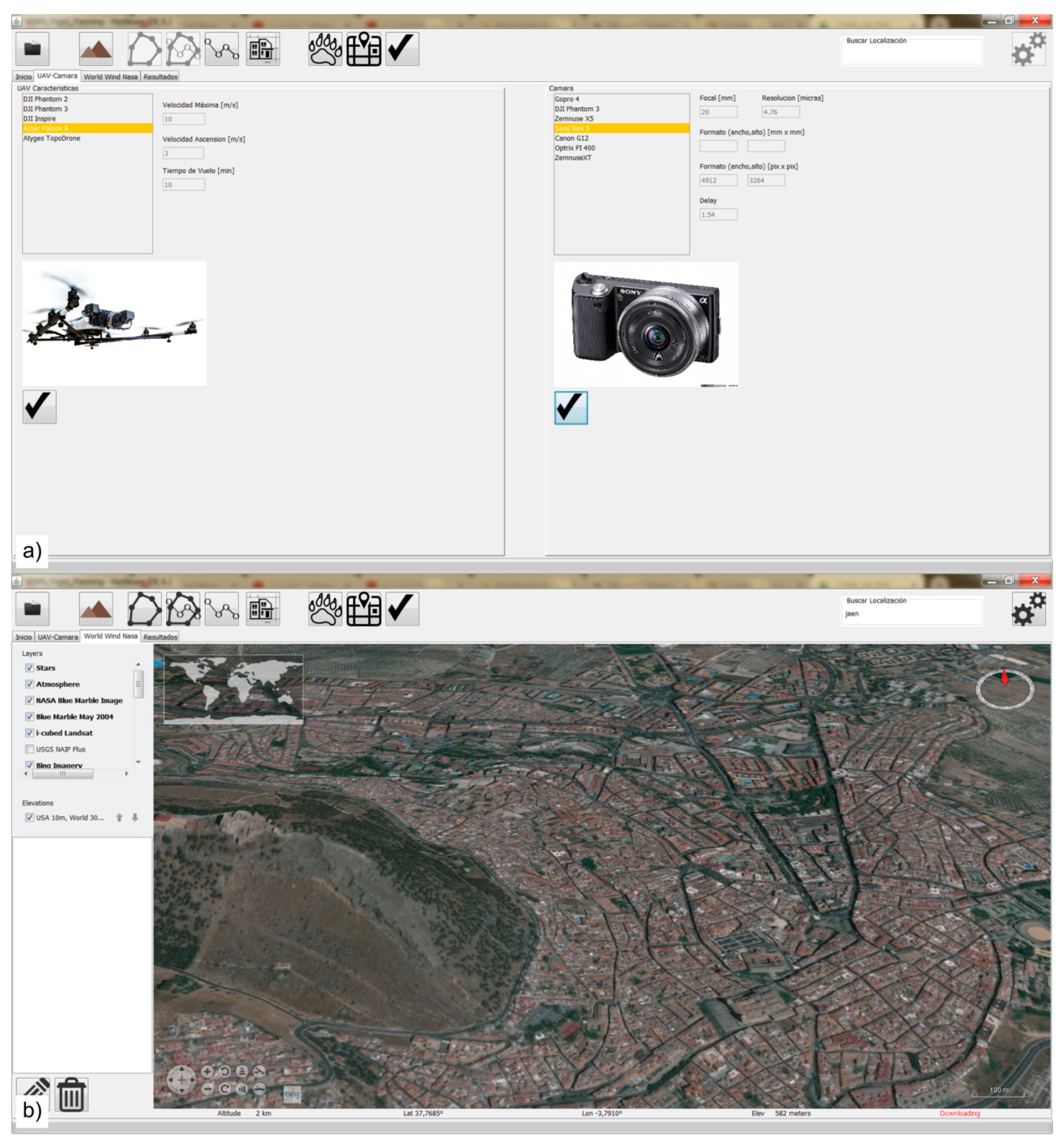
  • Integrated map: Consists of the obtaining of cartographic information to be used as a base map. Depending on the system, the base map can be a vector map, such as OpenStreetMap (e.g., Astec Navigator) (Figure 1a), with the possibility of uploading a georeferenced image to be used offline. However, the majority of base maps use georeferenced images downloaded from the Internet using map servers (e.g., Google or Bing) (Figure 1b). In these cases, the availability of an Internet connection is required in order to download these images, but once the images of the study zone are downloaded these applications can be run offline. The use of georeferenced image maps provides additional information for planning with respect to vector maps (e.g., identification of obstacles—trees, electricity lines, etc.).
  • 3D visualization: Consists of the availability of 3D views of the study zone (Figure 1c). This is an interesting feature for analyzing the terrain characteristics of the flight zone using a previously available Digital Elevation Model (DEM). For example, UgCS allows the importation of 3D building models in order to consider their volume and avoid possible collisions (mainly in cities).
  • Block flight planning: This is the common planning mode implemented in all systems. In this case, the study zone is defined using a rectangular polygon or a polygonal line (Figure 1d). Flight parameters can be derived from the definition of these limits. In addition, some tools use DEMs to plan flights (e.g., eMotion X and UgCS) (Figure 1c). Another important feature to consider is the possibility of obtaining the footprints of images. In this case, the application calculates and represents the projection of the photographs onto the ground, providing information about the coverages, overlaps, etc. This projection is usually realized in 2D considering a flat terrain or using only the four corners of the images and considering a real 3D projection over the terrain.
  • Corridor or linear flight planning: This feature allows users to plan flights covering study areas following a specific linear element (roads, rivers, etc.) (Figure 1e).
  • Circular or cylindrical flight planning: Circular flights are commonly implemented in all applications while cylindrical flights are simulated by adding several circular flights at different heights. This type of flight allows objects to be covered by convergent photographs (Figure 1f).
We consider eight items to analyze among current mission planning applications based on these categories. Table 1 describes the main characteristics of several mission planning applications considering these eight items:
  • VIM: Vector Integrated Map.
  • OIM: Orthoimages Integrated Map.
  • 3DV: 3D Visualization.
  • RBP: Block flight Planning (defined by a rectangle).
  • PBP: Block flight Planning (defined by a polygon).
  • DEM: Digital Elevation Model.
  • CFP: Corridor Flight Planning.
  • CCFP: Circular—Cylindrical Flight Planning.

3. Method

Once the most important features of the main existing mission planning applications have been described, it is possible to establish some additional issues to consider when surveying complex projects using RPAS. Therefore, we consider as complex scenes for photogrammetric studies those including one or several of these items:
  • Great variability of camera-object distances (differences in height in the case of vertical flights and depth in vertical elements such as buildings).
  • Presence of buildings or vertical objects to be surveyed.
  • Presence of occlusions or obstacles which block direct vision to the object (need of oblique images).
  • Requirement of stereo restitution.
  • Objects to be studied elevated from the ground (not included in DEM).
To resolve these issues, the mission planning applications should contain several functions:
  • Base map using a service of orthoimages and/or DEM.
  • 3D visualization.
  • Block and corridor flights considering a DEM.
  • Use of tilt images in planning.
  • Use of linear elements as real elements with physical characteristics (area, direction, inclination, etc.).
  • Circular and cylindrical flight planning considering CIPA recommendations for architectural surveys.
  • Quality control determining photographs coverage-maps and minimum, mean, and maximum GSD (considering DEM) before and after the flight execution.
The method proposed in this study tries to simplify the flight parameters calculation and quality control procedures as much as possible, in order to facilitate operations and provide a flexible methodology for developing new cases and solutions to applications in the future. The scheme (Figure 2) consists of two well-differentiated levels of operation. Core1 is dedicated to the calculation of basic parameters of the flight. The Core2 objective is to provide the necessary analysis for the geometric quality control of the block.
More specifically, the Core1 level has as its objective, the calculation of the position and orientation of the different waypoints depending on the characteristics of the images to be obtained (GSD and overlaps), the camera used (focal length, sensor size, and resolution), and the flight typology selected by the user and other technical or legal limitations (maximum flight height, maximum distance between the UAS and the ground control station, etc.). These calculations are usually implemented in all RPAS flight planning systems, although in this study, new typologies are considered for surveying complex scenes. In this case, additional functionalities have been incorporated, such as the DEM analysis both globally and locally (at strip level) to achieve a better adjustment of the distance between the camera and the object, and therefore, a value of GSD more throughout the block. The methodology used in this task starts from the calculations used in any photogrammetric project that can be consulted in any photogrammetry manual [46,47,48].
Core2 is oriented towards providing additional information for the development of quality assurance tasks prior to the execution of the flight (it can also be used for the quality control of flights already carried out). In this case, the terrain morphology is considered through the use of a preexisting DEM in the area. The basic element considered within this operation that is common to the different planning functions is the methodology known as ray casting [49,50], which is frequently used in processes of intervisibility analysis in 3D modeling procedures. The selected method (Figure 3a) focuses on the analysis of the visibility of a given object from the position and attitude of an observer (camera) [51,52].
Using ray casting method, it is possible to obtain an accurate projection of the images onto the ground, allowing the calculation of the real quality of the flight such as GSD (using the approach described by Höhle [53]), coverage, and overlaps. These parameters are greatly influenced by the distance between camera and object. This is especially critical in RPAS flights carried out at low height (usually less than 120 m). Using these projections (the footprints are calculated by considering 10 points of each border of the images and obtaining their intersection with the terrain, Figure 3b), it is possible to perform different analyses: (a) coverage (It is analysis of how many images appear at each point of the terrain according to a preestablished grid. This is used to estimate flight quality and plan the ground control point (GCP) distribution. An interesting study of GCP distribution using RPAS is described by Tonkin and Midgley [54]), (b) overlaps, and, (c) GSD (including minimum, mean, and maximum GSD values for the area covered by each image). All this contributes in an effective way to guaranteeing the flight adjustment to the conditions required. In the case of detecting a problem, it will be necessary to modify the initially established parameters.

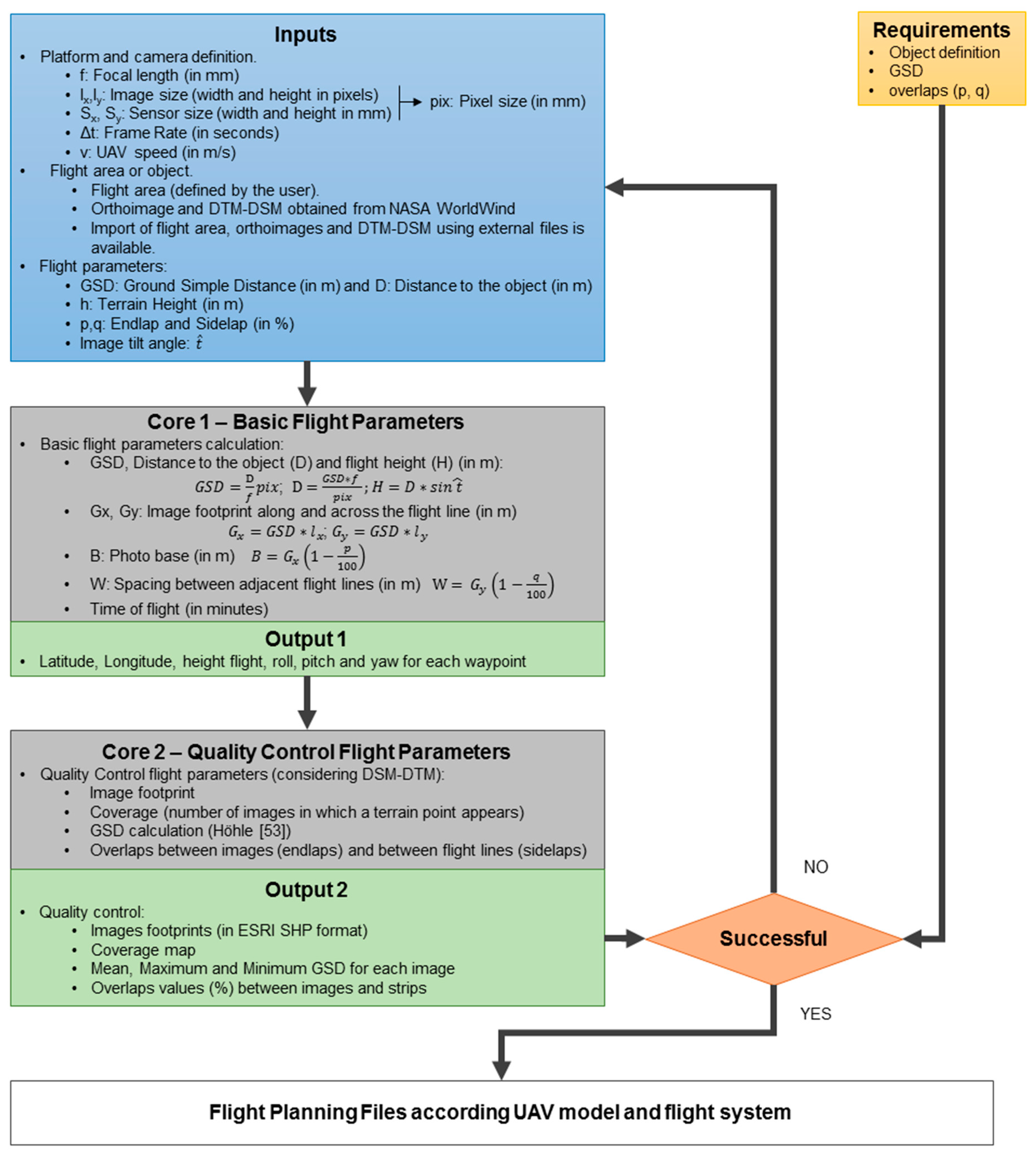
4. Software Development

The method employed to develop the software includes several tasks: (a) definition and application design, (b) software programming, and (c) monitoring real cases. In our software, called MFPlanner3D [55], some features stand out: (a) user interface and (b) use of DEM for flight parameters determination considering the real terrain surface, providing real image footprints and coverage map (number of images recorded at each terrain point). MFPlanner3D includes functions that improve the existing RPAS mission planning applications. It has been developed using NASA World Wind SDK (Software Development Kit) [56] in Java which includes:
  • Compatibility with all operating systems where Java is available.
  • A basic DEM is obtained from the Shuttle Radar Topographic Mission (SRTM) along with procedures for calculating intersections with the terrain (ray casting).
  • Importation and exportation tools for the main geospatial data sources (e.g., GeoTIFF, Shapefile).
  • Connection protocols to Web Map Service (WMS), Web Feature Service (WFS), and Web Coverage Service (WCS) and maps from Bing Maps and OpenStreetMap.
  • Use of the WGS84 reference system (system used in RPAS).
  • Use of UTM projection in area and distance calculations.
  • Use of the Earth Gravitational Model 1996 (EGM96) to determine orthometric heights.
Figure 4 shows some examples of MFPlanner3D user’s interface, including the project definition module (selection of parameters of UAV and camera) (Figure 4a) and flight planning module (using 3D visualization mode) (Figure 4b).
The main features for flight planning of MFPlanner3D are based on conventional or block, corridor, combined, and polygon extrusion flights. All these types can be used independently or combined depending on the scene to be studied. These cases are described below:

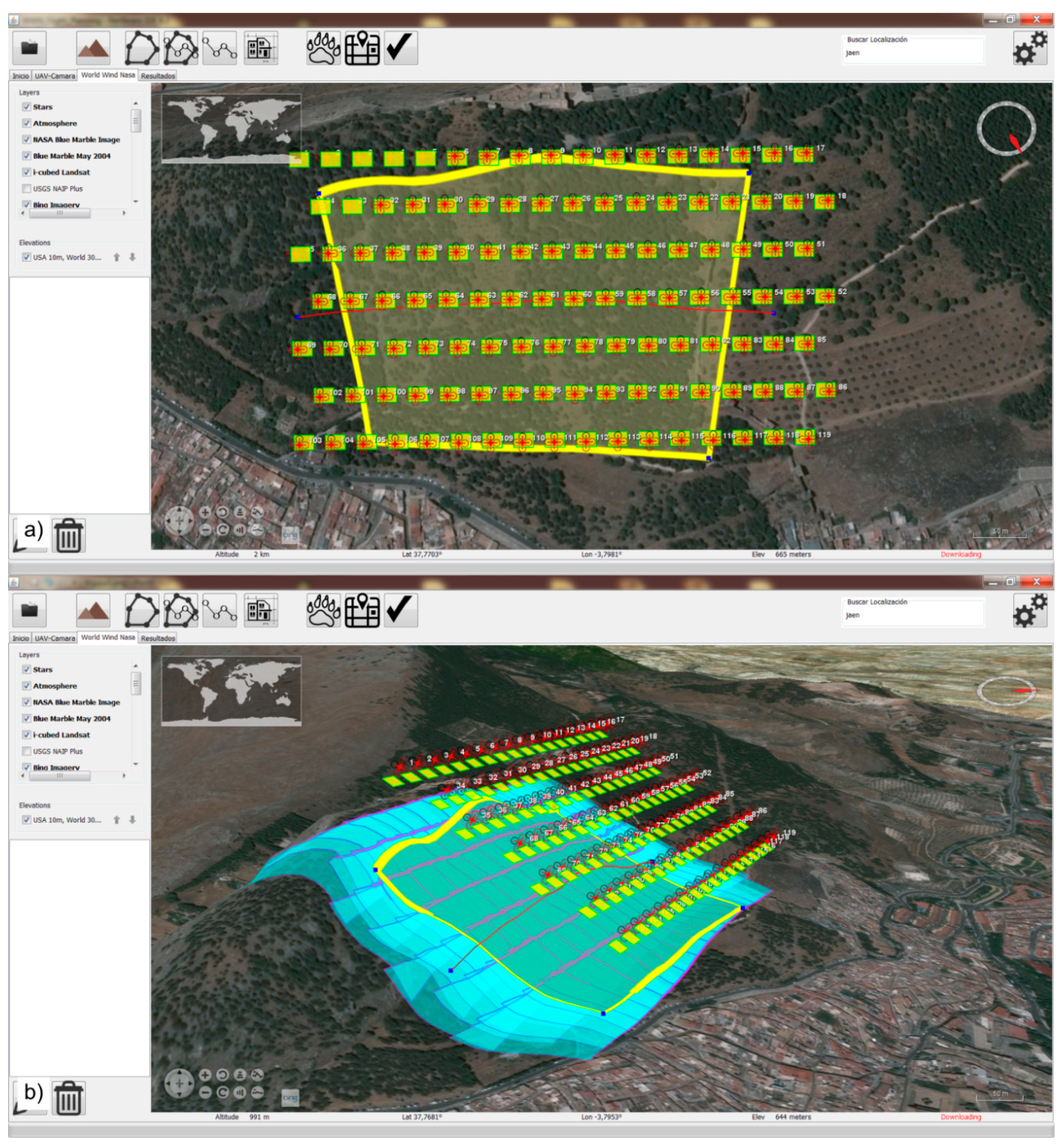
4.1. Conventional or Block Flight

This is the most common flight schema included in all applications. Our software includes some additional features useful for photogrammetric surveys. MFPlanner3D uses a polygon (drawn using 3D visualization interface) for the flight area definition, defining the most appropriate strips orientation. In this sense, flight lines are situated perpendicular to the line of maximum slope (using DEM). The calculation considers several input parameters such as overlap values (longitudinal and lateral), flight height (considering the final GSD value and restrictions established by regulations), etc. Additionally, flight parameters (number of strips and total images, flight time, etc.) are calculated in real time, making this application a complete interactive tool. The main improvement is DEM use for the best adjustment of the flight height of each strip considering the mean height of the terrain to be overflown. Although this function is also implemented in the eMotion X and UgCS applications, in our approach, we can consider the mean height of the zone or the mean height of each strip obtained from the waypoints. This last option is implemented in order to obtain a more continuous GSD in contrast to those that established the flight height at each waypoint individually. In addition, the flight height remains constant in each strip, avoiding continuous vertical displacements of the UAV. Some examples of planned flights for a sloped zone considering a DEM (or not) are shown in Figure 5.

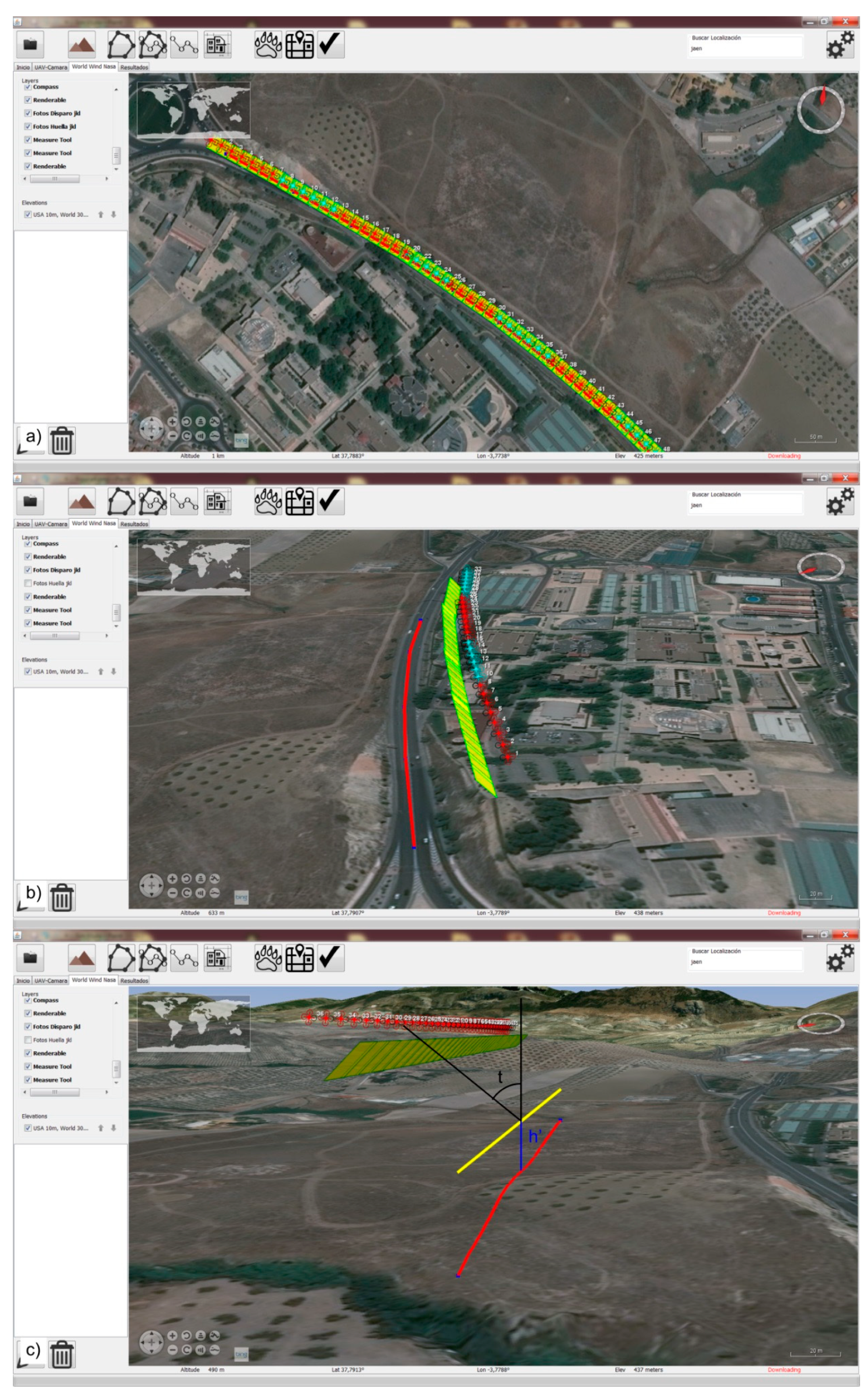
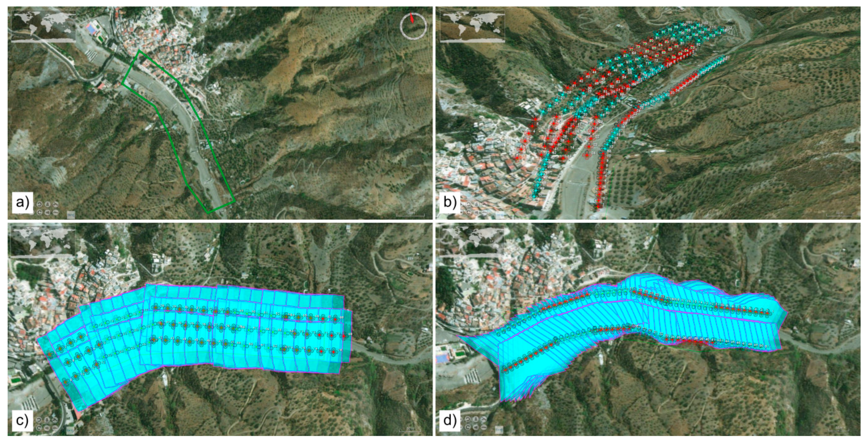
4.2. Corridor Flight

The corridor flight mode is used to plan a flight over a determined linear element (e.g., a road). The traditional approach consists of the definition of a polygonal line considered as the UAV trace and the flight parameters calculation in a similar way to the conventional block flight. In our system, a new feature is incorporated. This consists of the possibility of defining the line of objects to be surveyed in addition to the flight trace (used in other applications). Thanks to this improvement, users can define the distance and inclination necessary to capture this linear polygon considering a value of longitudinal overlap. The acquisition of oblique images was also described for several cases in literature. As an example, Trajkovski et al. [57] proposed a combination of vertical and oblique images for capturing the steep terrain. Figure 6 shows several examples considering the polygonal line as flight trace (Figure 6a) and the polygonal line as object trace to define oblique photographs with a tilt value (t) (Figure 6b). Figure 6c shows a plan using a defined height object (h’). This new approach definitely supposes an alternative to the traditional flights based on vertical images considering a predefined flight line. The possibility of including the height of the reference object with respect to the terrain is very useful in cases of studies where the object is elevated but the DEM did not include this object (e.g., Figure 6c shows a power line project). We consider this improvement to be very interesting in several case studies with vertical or sloped objects such as road slopes, architectural buildings, etc.

4.3. Combined Flight

This flight schema has been included as a novelty in this application. The combined flight consists of the combination of both modes previously described. The main objective is to cover situations where it is necessary to capture sloped zones (e.g., landslides). In these cases, it is interesting to capture photographs perpendicular to the slope plane in order to obtain more details, maintaining the scale in these zones or avoiding possible occlusions from vertical views. This is coherent with the data proposed by Trajkovski et al. [57] using a combination of vertical and oblique images to avoid large-scale changes and the reduced capture of details in the rugged terrain using vertical images. In our case, to define this mode, it is necessary to establish the flight direction perpendicular to the maximum slope line, the polygonal line defining the study area, and the inclination. Considering these data and the additional overlap values and flight height, the photograph positions are calculated automatically. As an example, Figure 7 shows a combined flight plan implemented over a slope. We highlight the fact that photograph positions and directions are adapted to the slope considering the DEM (note the footprints of photographs adapted to the terrain in Figure 7b).

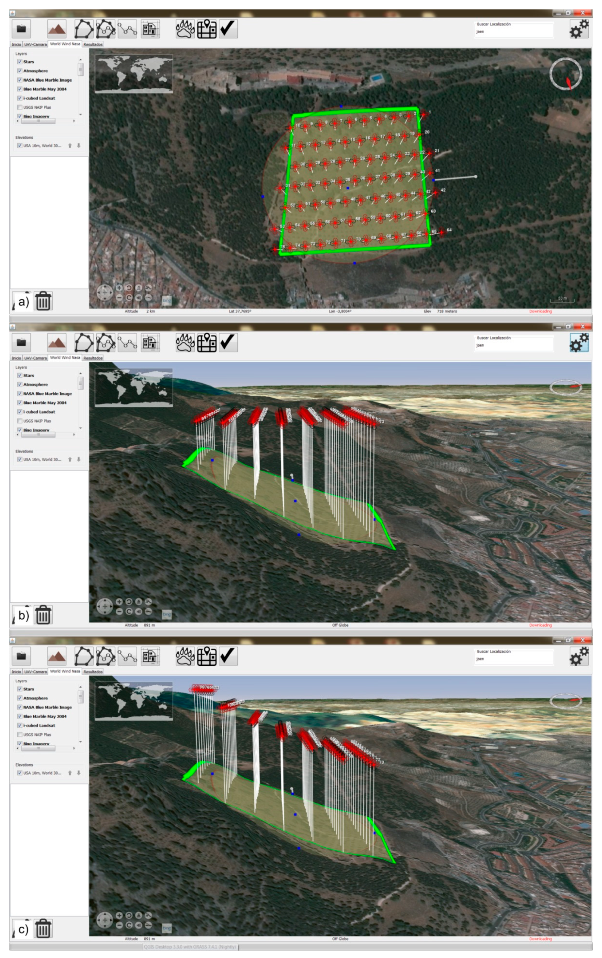
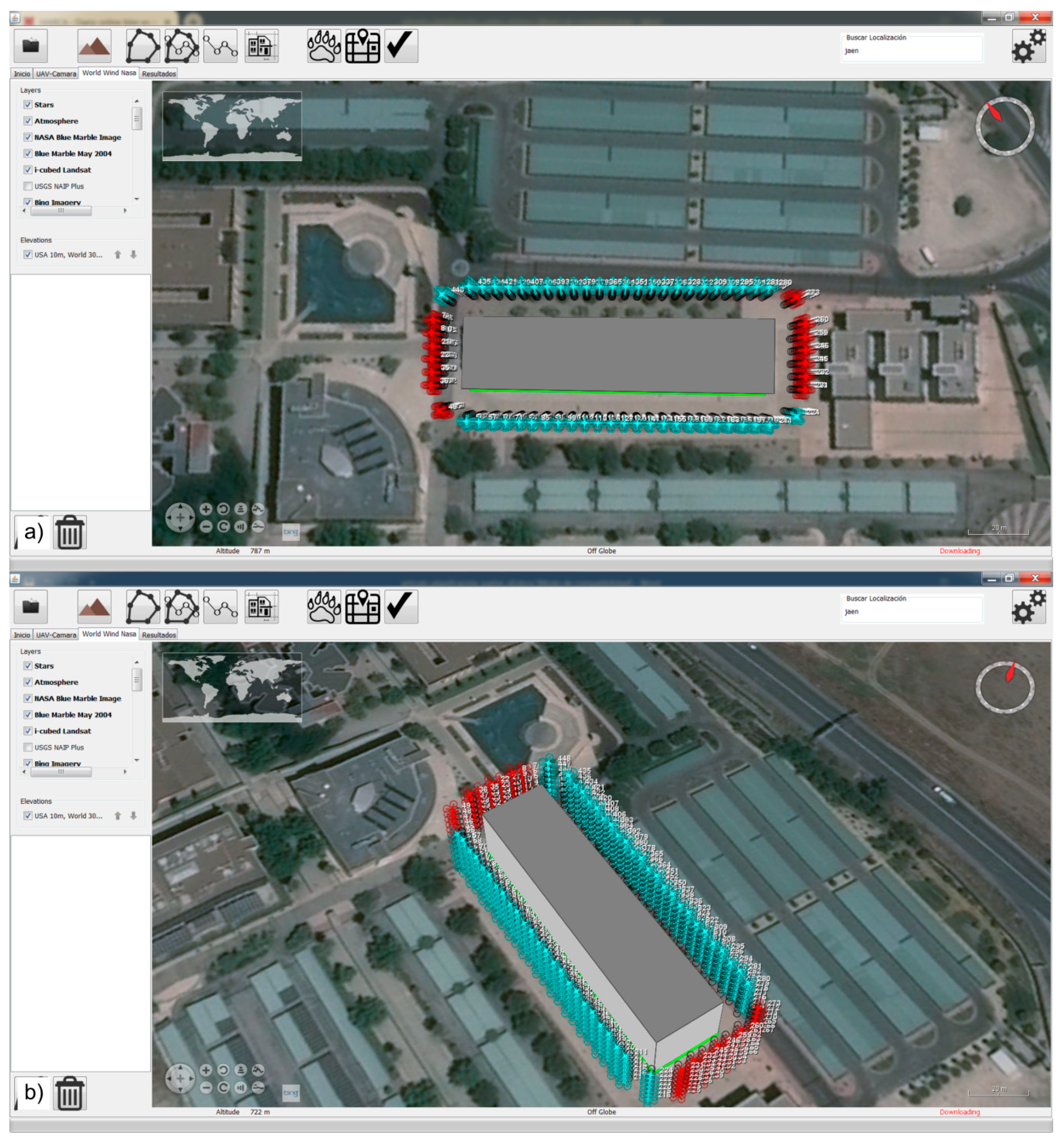
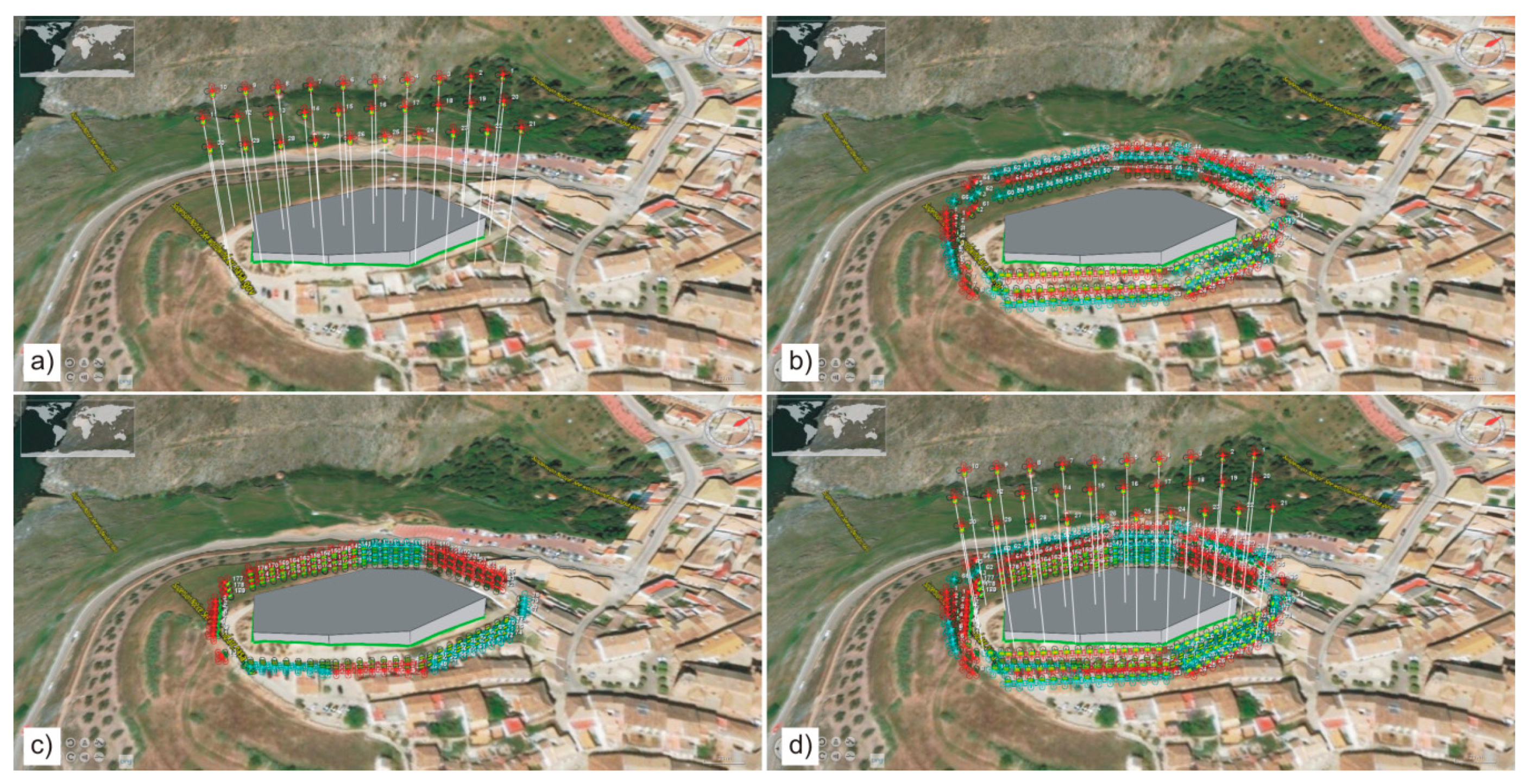
4.4. Polygon Extrusion Flight

The goal of this mode is related to implementing the CIPA’s rules in order to capture architectural buildings, which are not implemented in other applications. It is based on the vertical expansion of a 2D plane polygon in order to generate a 3D object. In this type of schema, we need to define the polygon of the base and the height of the object. The application calculates all parameters automatically, including some convergent photographs located in the corner zones. The geometry of photographs is calculated considering the vertical planes that define the buildings (Figure 8). This schema improves on those circular flights provided by several applications for surveying these objects because it allows the capturing of stereoscopic photographs (parallel axis), supporting stereo restitution.

5. Applications and Results

We have applied the new proposed approach to several real cases in order to test the application in complex scenes considering block, corridor, and vertical schemas. In addition, we also applied it to a terrestrial photogrammetric project using a mast and the quality control of a previously developed flight.

5.1. Block Flight Project

This mission planning was developed on a quarry zone with great relief variation (about 210 m). The main objective was to obtain a high-detailed DEM of the area using RPAS photogrammetry methodology. Therefore, great requirements of spatial accuracy and image geometry were established in order to obtain a good stereoscopic coverage for the DEM and 3D restitution tasks. This implies a constant scale in photographs (GSD value) and adequate overlap values.
To achieve this goal, it is necessary to propose an adequate control of the distance between the camera and the object (terrain), taking into account its own morphology. Figure 9 shows the importance of using a DEM to establish the correct geometry of the flight, something that is always true in any photogrammetric flight operation, but which in the case of RPAS is even more important when dealing with flights at low altitude. Here, the differences in the elevation of the terrain are proportionally very important, affecting the changes of GSD and overlaps in the images captured. The flight was planned considering an AscTec Falcon 8 RPAS with a GSD equal to 0.03 m and 80–60% overlap values (longitudinal and lateral). The flight height over the terrain was configured at 120 m, considering the Spanish regulations.
The results obtained (Figure 9c–h) show an important improvement of the flight when considering the height of the terrain using the DEM (in this case, a 5 m-resolution DEM, available from the Instituto Geográfico Nacional of Spain, was considered). First, Figure 9a,b shows the planned image locations (note that Figure 9b shows the flight height of each strip adapted to the mean value of the terrain). Figure 9c,d shows the image coverage maps of both flights. In both cases, the footprints are adapted to the terrain.
Considering the photograph coverage, the DEM-based option produces a more homogeneous image coverage, whereas the non-DEM-based option presents noncovered zones in the highest part of the study area (in red and transparent colors on the right part of Figure 9c). The DEM-based option shows that the entire zone was covered with at least three images (Figure 9d), whereas there were some zones with less than three images in the non-DEM-based option (Figure 9c).
These results were confirmed by the analysis of the GSD mean values (Figure 9e–h). In the first case (not DEM-based), there is a huge GSD variability, with values higher than 0.08 m (more than 2 GSD considering the desired GSD value), while the second case (DEM-based) showed more homogeneity of GSD values, with values lower than 0.06 m, according to the desired flight geometry.
The results show an improvement in the flight quality according to the desired values (GSD and overlaps) when the flight height variability is applied considering the DEM, obtaining more homogeneous images (GSD and overlap) and a high geometric flight quality.

5.2. Corridor Flight Project

The second example was developed considering a linear element (corridor flight). In this case, we need to obtain information about the terrain characteristics for a river erosion processes analysis. For this objective, we planned a multitemporal flights series in order to determine differences between the DEMs obtained from the images captured over time.
To perform this study, we required a flight along a river that covered adjacent zones where erosion processes are active. Considering the new flight schemas provided by MFPlanner3D, we used a combined flight (block and corridor flight) with the linear feature corresponding to the river stream and the block flight polygon covering the erosion areas (Figure 10).
In this case, we used a DJI Phantom 3 Pro. Basic flight configuration consisted of three different strips; one flight was developed along the river stream using vertical shots (0° tilt angle) and a flight height of 100 m (Figure 10b), considering 80% and 60% overlaps (longitudinal and lateral, respectively), and two additional convergent flights were developed using 30° tilted images, 65 m of flight height, and 75 m of distance to the object (Figure 10c). These additional convergent flights were performed in order to avoid problems derived from occlusions that could appear in the vertical flight and to improve orientation processes (using the SfM algorithm).

5.3. Vertical Object Case

The third case consisted of the flight planning developed in order to obtain a 3D model (using photogrammetry) of a castle (Burgalimar Castle in Spain) considering the recommendations provided by the CIPA for documenting heritage. Cardenal et al. [58] gave a more detailed description of this case study.
In addition to the 3D model, a set of orthorectified images were needed. In order to obtain these products, a set of stereoscopic and convergent photographs of the object were needed. Moreover, we also planned a block flight in order to obtain a correct coverage of the plan view of the castle. To summarize, we planned three flight schemas: (i) a block flight capturing vertical photographs, (ii) three corridor flights around the castle, acquiring oblique images at different heights, and (iii) a polygon extrusion flight to obtain the images of the vertical walls of the castle.
We used an AscTec Falcon 8 RPAS to perform all flights. The block flight was planned using a flight height of 50 m and 80% and 60% longitudinal and lateral overlaps, respectively (Figure 11a). The linear flights were carried out considering three flight heights of 10, 15, and 20 m and inclinations of 30°, 35°, and 40° (Figure 11b). All cases considered a distance with respect to the object of 20 m and longitudinal overlaps of 80%.
Finally, we defined a polygon coinciding with the perimeter of the castle. This polygon was used to establish a polygon extrusion flight with a height of 15 m. The flight was planned considering a distance with respect to the polygon of 10 m and 80% and 60% longitudinal and lateral overlaps, respectively (Figure 11c). Figure 11d shows a combination of the three flight planning cases.

5.4. Terrestrial Photogrammetry Using Masts

Although the program was designed with RPAS planning in mind, its flexibility allows it to be used also for the planning of other projects, both conventional aerial photogrammetry (with special attention to the quality control of the projects) and with other image capture schemes (e.g., terrestrial images). In this example, we used MFPlanner3D to plan a terrestrial photogrammetric project using a mast to lift the camera according to the method proposed in Pérez-García et al. [59].
The method consists of the establishment of several stations of the mast covering the study zone. From each station, eight oblique photographs were captured, turning the camera 45° horizontally between two adjacent photographs (Figure 12a,b). For this configuration, the basic parameters are the mast height, focal distance, and camera resolution, but a proper configuration of the different shots is not simple a priori. We used MFPlanner3D in order to obtain the optimal configuration of the images (number of stations, mast height, etc.) for the photogrammetric survey. In Figure 12c, we show the results obtained for 25 stations, using a 6 m mast height and 45° tilted images. In Figure 12d, the coverage map is shown.

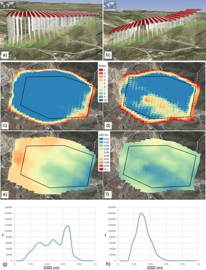
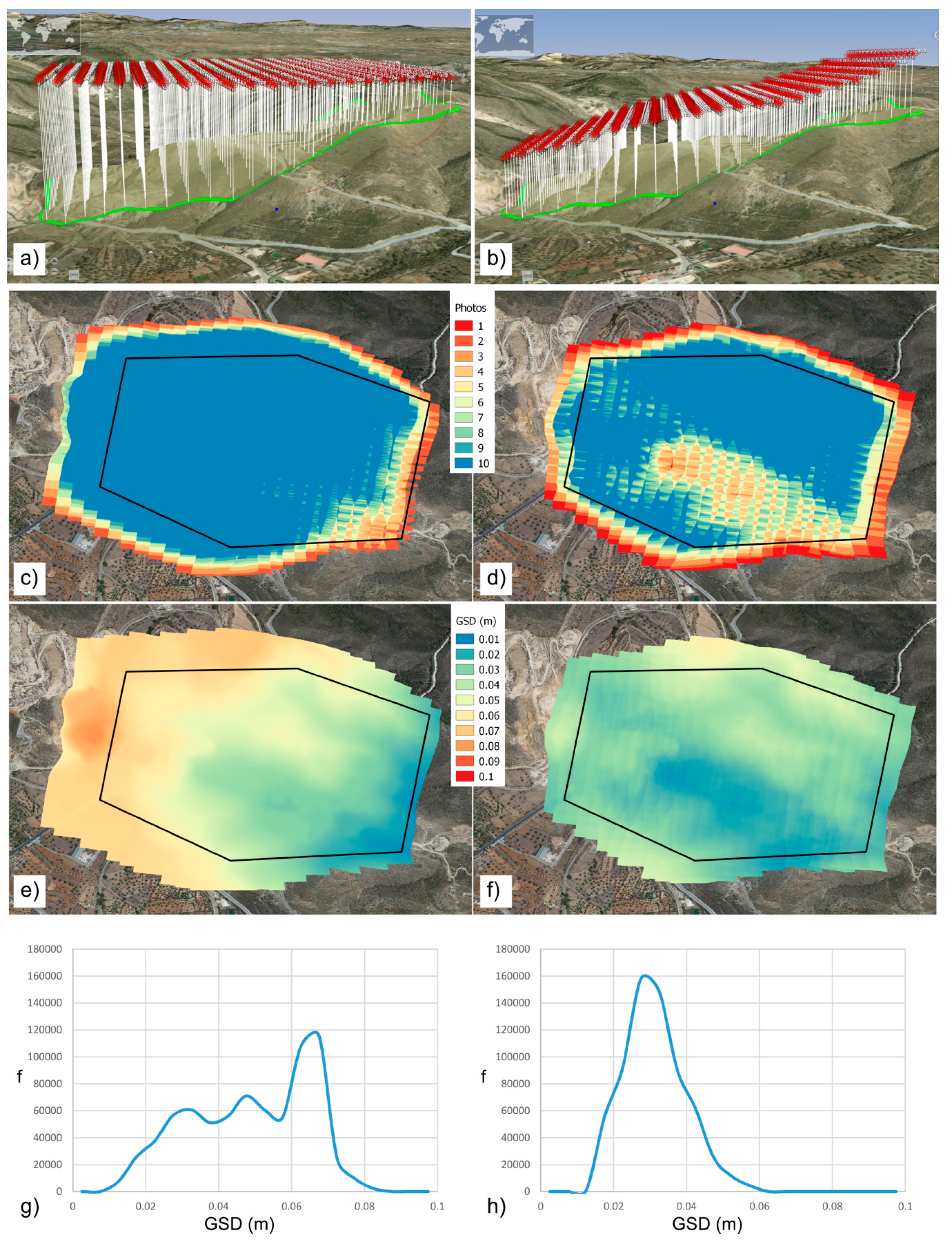
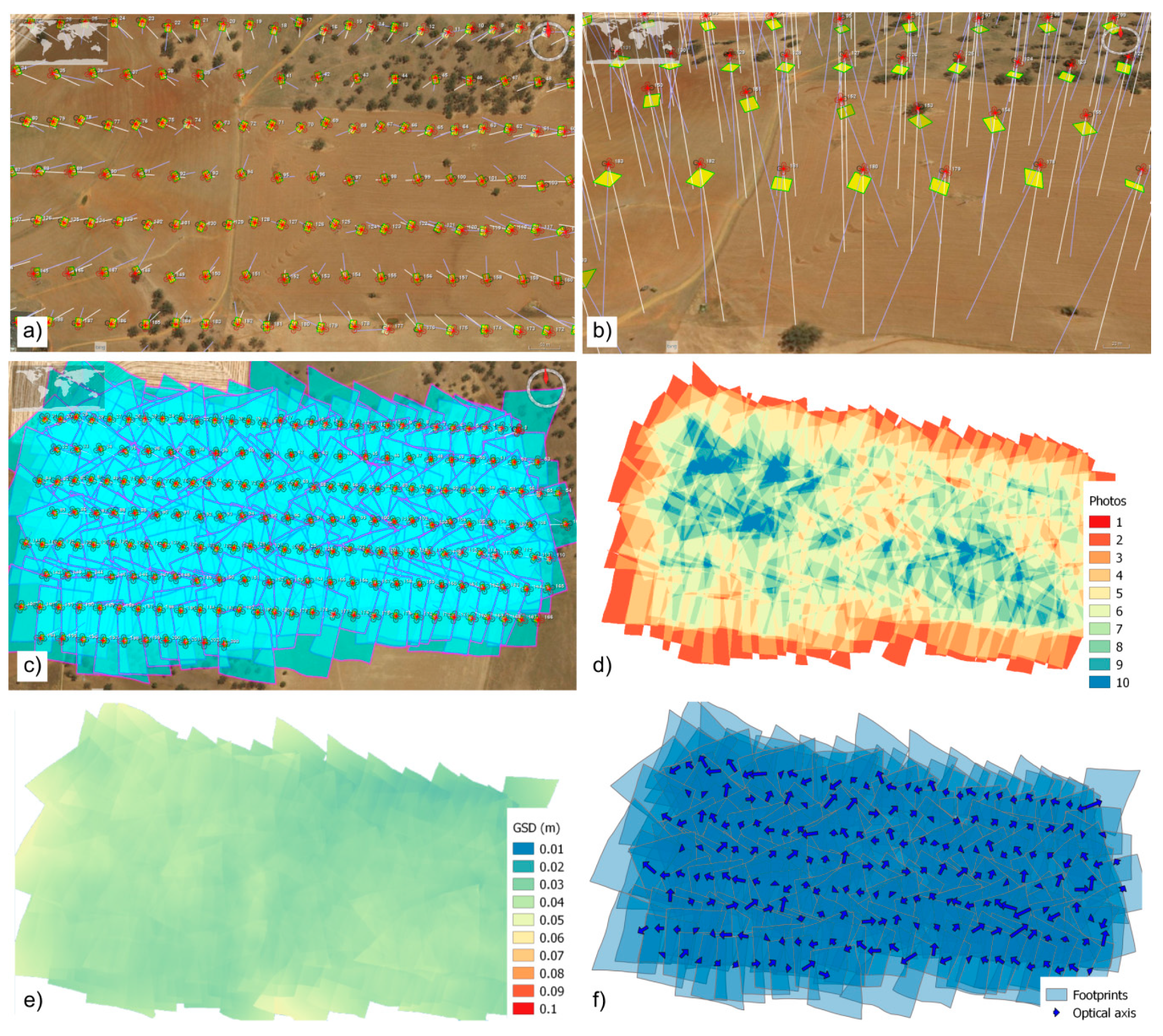
5.5. Quality Control of the RPAS Project

Any current photogrammetric project requires on the one hand, a careful planning of the shots to be taken and on the other hand, the verification that they have been executed according to the plan. The main objective is to guarantee the geometric quality of the images before beginning their analysis. In this paper, a methodology (and software) is proposed for the flight planning in order to avoid different problems in practical cases (scale, overlaps, GSD, etc.). MFPlanner3D can also be used for the quality control of existent (executed) flights. It is possible to control the geometry of the photographs by analyzing photograph coverage, overlaps, GSD values, and optical axes inclination using the camera characteristics and log file data.
In this example, a fixed-wing RPAS (Trimble UX5) flight was used. The flight execution was greatly affected by weather conditions, more specifically strong winds, which caused problems in the location and orientation of the camera for each shot (Figure 13a) and caused optical axis deviation that reached in some cases values of about 25° (Figure 13b). These aspects are very important considering that the large rotation of images decreases image block geometry quality with irregular overlaps and inconsistency of stereo models [60]. Using MFPlanner3D, we obtained the footprints map of photographs (Figure 13c), the coverage map (Figure 13d), the GSD map (Figure 13e), and the directions and modules (mainly caused by the inclination) of the optical axes (Figure 13f).

6. Discussion

The examples show the efficiency of the method and the application developed in this study in covering different scenarios in photogrammetric projects. In this sense, we included new flight schemas (e.g., combined and polygon extrusion modes) and a methodology for flight quality control based on image coverage maps and minimum, mean, and maximum GSD values.
The image coverage map provides an interesting method for checking the images’ geometry and could be useful for GCPs locations design. In UAV-SfM photogrammetry, the best option is to try to distribute the GCP evenly or homogeneously not only in the periphery but also in the center of the area [61] appearing in the highest number of images possible. In addition, Tonkin and Midgley [54] suggested the importance of a uniform GCP spatial distribution. Therefore, using these premises and the results obtained, we can analyze the scene and implement the best GCP placement. The combination of several flight configurations in the same project provides a more reliable structure because of the inclusion of photographs from several points of view, avoiding possible occlusions and providing more global terrain information. These are the most outstanding characteristics of the proposed approach, but there are more advantages to be noted. As examples, global 3D visualization, the use of DEM in order to obtain a best flight adjustment and real footprints, the possibility of including the height of the reference object with respect to the terrain level, etc.
This method introduces features that do not exist in the other RPAS mission plans with great importance in photogrammetric projects. Thus, six basic features can be considered (and included in Table 1):
  • Flight adjusted to DEM by strips (DEM-S).
  • Corridor Flight Planning by Objects (considering interest trajectories) (CFP-O).
  • Block and Corridor Combined Planning (B+C-CP).
  • Polygon Extrusion Planning (PEP).
  • Calculation of Coverage Maps using real Footprints projected onto the terrain (CM-RF).
  • Calculation of GSD value at the center of the photographs (C-GSD).

7. Conclusions

This study has described a new approach for the mission planning of RPAS photogrammetric flights. In this context, the main characteristics to be included in planning applications considering the issues that can appear in complex scenes have been identified. These complex scenes are usually conditioned by the terrain and the presence of objects or obstacles. To solve these difficulties, we have added two new flight mission schemas to the ones most commonly implemented in most flight mission planning applications (block, corridor, or circular). These new schemas are based on combined flights (block and corridor) and a polygon extrusion flight. The first one is suggested in cases where the object presents a great inclination (e.g., great slope) and combines both types of flight in order to minimize occlusions and facilitate orientation processes by including convergent photographs. The second was suggested in order to develop photogrammetric flights of buildings or vertical objects (e.g., walls). The main advantage of this new planning type is related to the obtaining of stereoscopic pairs of photographs (parallel axes) and convergent photographs in contrast to those developed using circular flights (convergent photographs). In addition, several improvements have also been suggested to the planning types most commonly used. Therefore, in the case of block flights, we considered the terrain behavior in order to establish a flight height by strip. In the case of the flight of linear elements, we considered the possibility of including inclined photographs and determining the height of the object displaced over the DEM in order to study objects not considered in the terrain (e.g., power lines, solar panels on parking covers, etc.).
In this approach, we have considered flight quality controls. First, we suggested the implementation of a control of the geometry of the photographs in the planning stage. More specifically, the main aspects of the photogrammetric flight related to scale, overlaps, GSD values, geometry, etc. must be analyzed using several resources such as photograph coverage maps and GSD maps. In addition to monitoring the flight planning, these products have a direct influence on other procedures such as the planning of the location of GCPs. Second, we also suggested the implementation of another control after the execution of the flight in order to check the geometry of the photographs acquired. This control must confirm that all parameters achieve the project requirements.
The approach developed in this study was applied using a research tool that implemented the functions and improvements described previously. This application was tested using several real cases including block, linear, combined, and polygon extrusion flights. The results have demonstrated the viability of the approach even in special cases, where the flight is simulated using a camera mounted on a mast and using oblique photographs. The quality controls developed have demonstrated their efficiency in detecting problems, previously and subsequently to the flight execution.
Our approach allows the planning of different types of flight. In a photogrammetric project, we can use as many flights as we need independently of their typology. In cases where the requirements are not achieved, we can design a combined flight using several types of flight. The quality control can show results of these flights both individually or combined to choose the best option to be implemented. This operability has been designed to cover those situations where a simple type of flight does not guarantee the compliance of the requirements of the project.
Future research will focus on planning flights using other sensors and taking into account their characteristics (e.g., LiDAR) and combinations of complex scenes such as those presented in cities.

Author Contributions

Conceptualization, José Miguel Gómez-López, José Luis Pérez-García, Antonio Tomás Mozas-Calvache and Jorge Delgado-García; Investigation, José Miguel Gómez-López, José Luis Pérez-García, Antonio Tomás Mozas-Calvache and Jorge Delgado-García; Methodology, José Miguel Gómez-López, José Luis Pérez-García, Antonio Tomás Mozas-Calvache and Jorge Delgado-García; Software, José Miguel Gómez-López; Validation, José Miguel Gómez-López, José Luis Pérez-García, Antonio Tomás Mozas-Calvache and Jorge Delgado-García; Writing—original draft, José Miguel Gómez-López, José Luis Pérez-García, Antonio Tomás Mozas-Calvache and Jorge Delgado-García; Writing—review & editing, José Miguel Gómez-López, José Luis Pérez-García, Antonio Tomás Mozas-Calvache and Jorge Delgado-García. All authors have read and agreed to the published version of the manuscript.

Funding

This research received no external funding.

Conflicts of Interest

The authors declare no conflicts of interest.

References

  1. Colomina, I.; Molina, P. Unmanned aerial systems for photogrammetry and remote sensing: A review. ISPRS J. Photogramm. Remote Sens. 2014, 92, 79–97. [Google Scholar] [CrossRef] [Green Version]
  2. Nex, F.; Remondino, F. UAV for 3D mapping applications: A review. Appl. Geomat. 2014, 6, 1–15. [Google Scholar] [CrossRef]
  3. Pajares, G. Overview and current status of remote sensing applications based on unmanned aerial vehicles (UAVs). Photogramm. Eng. Remote Sens. 2015, 81, 281–330. [Google Scholar] [CrossRef] [Green Version]
  4. Xiang, T.; Xia, G.; Zhang, L. Mini-unmanned aerial vehicle-based remote sensing: Techniques, applications, and prospects. IEEE Geosci. Remote Sens. Mag. 2019, 7, 29–63. [Google Scholar] [CrossRef] [Green Version]
  5. Sharma, J.B. (Ed.) Applications of Small Unmanned Aircraft Systems: Best Practices and Case Studies; CRC Press: New York, NY, USA, 2019. [Google Scholar]
  6. Yao, H.; Qin, R.; Chen, X. Unmanned aerial vehicle for remote sensing applications—A review. Remote Sens. 2019, 11, 1443. [Google Scholar] [CrossRef] [Green Version]
  7. Weibel, R.; Hansman, R.J. Safety considerations for operation of different classes of UAVS in the NAS. In AIAA 4th Aviation Technology, Integration and Operations (ATIO) Forum, 6421; American Institute of Aeronautics and Astronautics: Chicago, IL, USA, 2004. [Google Scholar]
  8. Arjomandi, M.; Agostino, S.; Mammone, M.; Nelson, M.; Zhou, T. Classification of unmanned aerial vehicles. Mech. Eng. 2006, 3016, 1–48. [Google Scholar]
  9. Gupta, S.G.; Ghonge, M.M.; Jawandhiya, P.M. Review of unmanned aircraft system (UAS). Int. J. Adv. Res. Comput. Eng. Technol. (IJARCET) 2013, 2, 1646–1658. [Google Scholar] [CrossRef]
  10. Ren, L.; Castillo-Effen, M.; Yu, H.; Johnson, E.; Yoon, Y.; Nakamura, T.; Ippolito, C.A. Small Unmanned Aircraft System (sUAS) categorization framework for low altitude traffic services. In Proceedings of the IEEE/AIAA 36th Digital Avionics Systems Conference (DASC), St. Petersburg, FL, USA, 17–21 September 2017. [Google Scholar]
  11. Boletín Oficial del Estado (BOE). Real decreto 1036/2017 de 15 de diciembre. Bol. Estado 2017, 316, 129609–129641.
  12. Hassanalian, M.; Abdelkefi, A. Classifications, applications, and design challenges of drones: A review. Prog. Aerosp. Sci. 2017, 91, 99–131. [Google Scholar] [CrossRef]
  13. Toth, C.; Jóźków, G. Remote sensing platforms and sensors: A survey. ISPRS J. Photogramm. Remote Sens. 2016, 115, 22–36. [Google Scholar] [CrossRef]
  14. Global Drone Regulations Database. Available online: https://www.droneregulations.info (accessed on 5 May 2020).
  15. Gandor, F.; Rehak, M.; Skaloud, J. Photogrammetric mission planner for RPAS. ISPRS Int. Arch. Photogramm. Remote Sens. Spat. Inf. Sci. 2015, XL-1/W4, 61–65. [Google Scholar] [CrossRef] [Green Version]
  16. Karara, H.M. Close-range photogrammetry: Where are we and where are we heading? Photogramm. Eng. Remote Sens. 1985, 51, 537–544. [Google Scholar]
  17. Schwidefsky, K.; Ackermann, F. Photogrammetrie; BG Teubner: Stuttgart, Germany, 1976. [Google Scholar]
  18. Warner, W.S.; Graham, R.W.; Read, R.E. Small format aerial photography. ISPRS J. Photogramm. Remote Sens. 1996, 51, 316–317. [Google Scholar]
  19. Kraus, K. Photogrammetry: Geometry from Images and Laser Scans; Walter de Gruyter: Berlin, Germany, 2011. [Google Scholar]
  20. Atkinson, K.B. Close Range Photogrammetry and Machine Vision; Whittles Publishing: Caithness, Scotland, 1996. [Google Scholar]
  21. Luhmann, T.; Robson, S.; Kyle, S.; Harley, I. Close Range Photogrammetry: Principles, Techniques and Applications; John Wiley & Sons: New York, NY, USA, 2006. [Google Scholar]
  22. Fraser, C. Advances in close-range photogrammetry. In Photogrammetric Week; University of Stuttgart: Stuttgart, Germany, 2015; pp. 257–268. [Google Scholar]
  23. Waldhäusl, P.; Ogleby, C.L. 3 × 3 rules for simple photogrammetric documentation of architecture. ISPRS Int. Arch. Photogramm. Remote Sens. 1994, 30, 426–429. [Google Scholar]
  24. CIPA. Photogrammetric Capture, the ‘3 × 3’ Rules. Available online: https://www.cipaheritagedocumentation.org/wp-content/uploads/2017/02/CIPA__3x3_rules__20131018.pdf (accessed on 5 May 2020).
  25. Ullman, S. The interpretation of structure from motion. Proc. R. Soc. Lond. Ser. B 1979, 203, 405–426. [Google Scholar]
  26. Koenderink, J.J.; Van Doorn, A.J. Affine structure from motion. J. Opt. Soc. Am. A 1991, 8, 377–385. [Google Scholar] [CrossRef]
  27. Lowe, D.G. Distinctive image features from scale-invariant keypoints. Int. J. Comput. Vis. 2004, 60, 91–110. [Google Scholar] [CrossRef]
  28. Brutto, M.L.; Meli, P. Computer vision tools for 3D modelling in archaeology. In Proceedings of the International Conference on Cultural Heritage, Lemesos, Cyprus, 29 October–3 November 2012. [Google Scholar]
  29. Szeliski, R. Computer Vision: Algorithms and Applications. Texts in Computer Science; Springer: London, UK, 2010. [Google Scholar]
  30. Westoby, M.J.; Brasington, J.; Glasser, N.F.; Hambrey, M.J.; Reynolds, J.M. ‘Structure-from-motion’ photogrammetry: A low-cost, effective tool for geoscience applications. Geomorphology 2012, 179, 300–314. [Google Scholar] [CrossRef] [Green Version]
  31. Damilano, L.; Guglieri, G.; Quagliotti, F.; Sale, I.; Lunghi, A. Ground control station embedded mission planning for UAS. J. Intell. Robot. Syst. 2013, 69, 241–256. [Google Scholar] [CrossRef]
  32. Pepe, M.; Fregonese, L.; Scaioni, M. Planning airborne photogrammetry and remote-sensing missions with modern platforms and sensors. Eur. J. Remote Sens. 2018, 51, 412–435. [Google Scholar] [CrossRef]
  33. Intel Asctec Navigator. Available online: https://downloadcenter.intel.com/download/26931/Downloads-for-Intel-Falcon-8-UAS (accessed on 5 May 2020).
  34. Mikrokopter Tool. Available online: https://wiki.mikrokopter.de/en/Software (accessed on 5 May 2020).
  35. Drone Deploy. Available online: https://www.dronedeploy.com/ (accessed on 5 May 2020).
  36. ArduPilot Mission Planner. Available online: https://ardupilot.org/planner/ (accessed on 5 May 2020).
  37. UgCS. Available online: https://www.ugcs.com/ (accessed on 5 May 2020).
  38. Hernandez-Lopez, D.; Felipe-Garcia, B.; Gonzalez-Aguilera, D.; Arias-Perez, B. An automatic approach to UAV flight planning and control for photogrammetric applications. Photogramm. Eng. Remote Sens. 2013, 79, 87–98. [Google Scholar] [CrossRef]
  39. Israel, M.; Mende, M.; Keim, S. UAVRC, a generic MAV flight assistance software. ISPRS Int. Arch. Photogramm. Remote Sens. Spat. Inf. Sci. 2015, 40, 287–291. [Google Scholar] [CrossRef] [Green Version]
  40. Mera Trujillo, M.; Darrah, M.; Speransky, K.; DeRoos, B.; Wathen, M. Optimized flight path for 3D mapping of an area with structures using a multirotor. In Proceedings of the International Conference on Unmanned Aircraft Systems (ICUAS), Arlington, VA, USA, 7–10 June 2016; pp. 905–910. [Google Scholar]
  41. Martin, R.A.; Blackburn, L.; Pulsipher, J.; Franke, K.; Hedengren, J.D. Potential benefits of combining anomaly detection with view planning for UAV infrastructure modeling. Remote Sens. 2017, 9, 434. [Google Scholar] [CrossRef] [Green Version]
  42. DJI Ground Station Pro. Available online: https://www.dji.com/es/ground-station-pro (accessed on 5 May 2020).
  43. Sensefly eMotion. Available online: https://www.sensefly.com/software/emotion/ (accessed on 5 May 2020).
  44. Pix4D Capture. Available online: https://www.pix4d.com/product/pix4dcapture/ (accessed on 5 May 2020).
  45. Map Pilot for DJI. Available online: https://support.dronesmadeeasy.com/ (accessed on 5 May 2020).
  46. Wolf, P.R.; Dewitt, B.A.; Wilkinson, B.E. Elements of Photogrammetry with Application in GIS, 4th ed.; Mc Graw-Hill: Boston, MA, USA, 2014. [Google Scholar]
  47. Mikhail, E.M.; Bethel, J.S.; McGlone, J.C. Introduction to Modern Photogrammetry; John Wiley & Sons: New York, NY, USA, 2001. [Google Scholar]
  48. McGlone, J.C. Manual of Photogrammetry, 6th ed.; American Society of Photogrammetry and Remote Sensing: Bethesda, MD, USA, 2013. [Google Scholar]
  49. Appel, A. Some techniques for shading machine renderings of solids. In Proceedings of the AFIPS Spring Joint Computer Conference, Atlantic City, NJ, USA, 30 April–2 May 1968; pp. 37–45. [Google Scholar]
  50. Whitted, T. An improved illumination model for shaded display. In Proceeding of the 6th Annual Conference on Computer Graphics and Interactive Techniques, Seattle, WA, USA, 14–18 July 1980; Volume 23, pp. 343–349. [Google Scholar]
  51. Foley, J.D.; van Dam, A.; Feiner, S.K.; Hughes, J.F. Computer Graphics: Principle and Practice; Addison-Wesley: Boston, MA, USA, 1995. [Google Scholar]
  52. Fan, M.; Tang, M.; Dong, J. A review of real-time terrain rendering techniques. In Proceedings of the 8th International Conference on Computer Supported Cooperative Work in Design, Xiamen, China, 26–28 May 2004; pp. 685–691. [Google Scholar]
  53. Höhle, J. Oblique aerial images and their use in cultural heritage documentation. ISPRS Int. Arch. Photogramm. Remote Sens. Spat. Inf. Sci. 2013, XL-5/W2, 349–354. [Google Scholar]
  54. Tonkin, T.N.; Midgley, N.G. Ground-control networks for image based surface reconstruction: An investigation of optimum survey designs using UAV derived imagery and structure-from-motion photogrammetry. Remote Sens. 2016, 8, 786. [Google Scholar] [CrossRef] [Green Version]
  55. MFPlanner3D. Available online: https://github.com/jmgl0003/MFPlanner3D (accessed on 5 May 2020).
  56. NASA Worldwind. Available online: http://github.com/NASAWorldWind (accessed on 5 May 2020).
  57. Trajkovski, K.K.; Grigillo, D.; Petrovic, D. Optimization of UAV flight missions in steep terrain. Remote Sens. 2020, 12, 1293. [Google Scholar] [CrossRef] [Green Version]
  58. Cardenal, J.; Pérez, J.L.; Mata, E.; Delgado, J.; Gómez-López, J.M.; Colomo, C.; Mozas, A. Recording and modeling of fortresses and castles with UAS. Some study cases in Jaén (Southern Spain). ISPRS Int. Arch. Photogramm. Remote Sens. Spat. Inf. Sci. 2016, XLI-B5, 207–214. [Google Scholar] [CrossRef]
  59. Pérez-García, J.L.; Mozas-Calvache, A.T.; Gómez-López, J.M.; Jiménez-Serrano, A. 3D modelling of large archaeological sites using images obtained from masts. Application to Qubbet el-Hawa site (Aswan, Egypt). Archaeol. Prospect. 2019, 26, 121–135. [Google Scholar]
  60. Yang, Y.; Lin, Z.; Liu, F. Stable imaging and accuracy issues of low-altitude unmanned aerial vehicle photogrammetry systems. Remote Sens. 2016, 8, 316. [Google Scholar] [CrossRef] [Green Version]
  61. Sanz-Ablanedo, E.; Chandler, J.H.; Rodríguez-Pérez, J.R.; Ordóñez, C. Accuracy of unmanned aerial vehicle (UAV) and SfM photogrammetry survey as a function of the number and location of ground control points used. Remote Sens. 2018, 10, 1606. [Google Scholar] [CrossRef] [Green Version]
Figure 1. Examples of RPAS mission planners: (a) Astec Navigator using OpenStreetMap; (b) Mission Planner displaying Bing Aerial Image; (c) UgCS planning module using a block flight determined by a polygon limit using a Digital Elevation Model (DEM); (d) image footprints in Astec Navigator block flight; (e) image footprints in Astec Navigator corridor flight; and (f) circular flight planning in DJI GS Pro.
Ijgi 09 00392 g001
Figure 2. Schema of definition and application design.
Ijgi 09 00392 g002
Figure 3. (a) Forward ray casting method and (b) application to a real case using MFPlanner3D.
Ijgi 09 00392 g003
Figure 4. MFPlanner3D user’s interface: (a) project definition module and (b) flight planning module.
Ijgi 09 00392 g004
Figure 5. Example of conventional block flight on a sloped zone: (a) sloped zone delimited by polygonal line, (b) flight planned not considering the DEM, and (c) flight planned considering the DEM (with the best estimation of the mean ground sample distance (GSD)).
Ijgi 09 00392 g005
Figure 6. Examples of corridor flights: (a) corridor planning based on vertical photographs over the trace; (b) tilted images for a linear object; (c) tilted images of the linear object elevated (h’) from the ground.
Ijgi 09 00392 g006
Figure 7. Example of combined flight: (a) block and corridor combined flight and (b) real footprints obtained considering the DEM.
Ijgi 09 00392 g007
Figure 8. Example of polygon extrusion flight.
Ijgi 09 00392 g008
Figure 9. Influence of terrain morphology on block flight planning: (a) image locations using no-DEM option (flight height constant over terrain), (b) image locations using DEM option (variable flight height in strips considering terrain height), (c) and (d) number of recorded images (coverage map) for both projects, (e) and (f) GSD values for both projects, (g) and (h) frequency (number of cases) of GSD variation for both projects.
Ijgi 09 00392 g009
Figure 10. Linear case planning: (a) study zone, (b) position and orientation of planned images, (c) block flight, and (d) convergent flight.
Ijgi 09 00392 g010
Figure 11. Planning of the castle case: (a) block flight, (b) corridor flights considering 5° and 30° inclination angles, (c) polygon extrusion flight, and (d) combination of the three flights.
Ijgi 09 00392 g011
Figure 12. Mission planning of terrestrial photogrammetry using mast: (a) and (b) image locations (lateral and top views, respectively), (c) footprint map, and (d) images coverage map.
Ijgi 09 00392 g012
Figure 13. Control quality of a fixed-wing Remotely Piloted Aerial Systems (RPAS) flight: (a) and (b) image location of photographs (top and lateral views), (c) footprints map, (d) coverage map, (e) GSD map, and (f) direction and module (tilt angle) of optical axes.
Ijgi 09 00392 g013
Table 1. Main features of mission planning applications related to the most used platforms.
ApplicationVIMOIM3DVRBPPBPDEMCFPCCFP
DJI GS Pro [42]
AscTec Navigator [33]*
eMotion X [43] ***
MikroKopter Tool [34] ***
Mission Planner [36] *****
DroneDeploy [35]
Pix4D Capture [44]
Map Pilot for DJI [45]
UgCS [37]***
Notes: * User must georeference the image or use a Mapbox account. ** Indicates height information *** It allows planning photographs following a line at a certain distance interval from a determined origin point.

