Article

A Model-Based Approach for Adaptable Middleware Evolution in WSN Platforms

1
DEWS Center, University of L’Aquila, 67100 L’Aquila, Italy
2
DISIM, University of L’Aquila, 67100 L’Aquila, Italy
*
Author to whom correspondence should be addressed.
These authors contributed equally to this work.
J. Sens. Actuator Netw. 2021, 10(1), 20; https://0-doi-org.brum.beds.ac.uk/10.3390/jsan10010020
Submission received: 2 December 2020 / Revised: 11 February 2021 / Accepted: 23 February 2021 / Published: 4 March 2021
(This article belongs to the Special Issue QoS in Wireless Sensor/Actuator Networks)

Abstract

:
Advances in technology call for a parallel evolution in the software. New techniques are needed to support this dynamism, to track and guide its evolution process. This applies especially in the field of embedded systems, and certainly in Wireless Sensor Networks (WSNs), where hardware platforms and software environments change very quickly. Commonly, operating systems play a key role in the development process of any application. The most used operating system in WSNs is TinyOS, currently at its TinyOS 2.1.2 version. The evolution from TinyOS 1.x and TinyOS 2.x made the applications developed on TinyOS 1.x obsolete. In other words, these applications are not compatible out-of-the-box with TinyOS 2.x and require a porting action. In this paper, we discuss on the porting of embedded system (i.e., Wireless Sensor Networks) applications in response to operating systems’ evolution. In particular, using a model-based approach, we report the porting we did of Agilla, a Mobile-Agent Middleware (MAMW) for WSNs, on TinyOS 2.x, which we refer to as Agilla 2. We also provide a comparative analysis about the characteristics of Agilla 2 versus Agilla. The proposed Agilla 2 is compatible with TinyOS 2.x, has full capabilities and provides new features, as shown by the maintainability and performance measurement presented in this paper. An additional valuable result is the architectural modeling of Agilla and Agilla 2, missing before, which extends its documentation and improves its maintainability.

1. Introduction

Wireless Sensor Networks (WSNs) represent a class of IoT platforms that consist of small, resource-constrained and battery-powered motes. WSNs are usually characterized by lightweight software, in which design and management are rather complex, and heterogeneity of hardware platforms, which is usually addressed in WSN by using small operating systems (e.g., TinyOS [1], Contiki [2], RIOT [3]). Software complexity and platforms heterogeneity are often overcome by adopting a middleware (MW). To mitigate the software complexity, the software design shall ensure maintainability [4] and upgradability.
Unfortunately, these requirements are not fulfilled by design by several WSN applications and upgrades of the operating system may result in the impossibility to run these applications on motes mounting the new OS version.
In this paper, we propose a novel approach to support the evolution of legacy embedded systems software applications when low-level underlying software layers do not offer backward compatibility. The approach guides the software evolution towards better maintainability and better upgradability, while improving the software architecture to be more flexible to future updates and modifications.
In particular, the punctual contribution of this paper are the following:
  • We define a model-based porting approach of applications for embedded systems, with focus on WSN applications, required whenever the underlying software layers (e.g., the operating system) are evolved/updated. Through this approach the quality of the resulting application is improved and a low effort is required to get a working version of the application on the new release of the underlying software layer;
  • The model-based approach presented in this paper is the generalization of the methodology we initially adopted in our previous work on Agilla [5], which represents a specific use-case for this general method. Indeed, the methodology is now improved and formalized better. Its validity is demonstrated on Agilla as use-case: we define the general model-based approach, and then we cut it into details showing how it led to the results obtained in Reference [5], along with discussions on the intermediate results and on the effects of the model-based porting to the Agilla internals. The result of the porting (Agilla 2) is available to the research community on the Github platform [6].
  • We define and measure some relevant metrics (e.g., number of source code lines, storage occupation, code dependency degree) to evaluate the quality of Agilla 2 in comparison with the original version of Agilla. The result of the comparison shows that Agilla 2 has a more flexible software architecture at the cost of a negligible impact on performances.
  • In order to provide a further validation, we use the data and the models obtained from the proposed approach to add new energy-aware capabilities to Agilla 2, making it suitable for energy-sensitive applications. We demonstrate that, using the proposed approach, the integration of such relevant new features is possible with a reduced time and complexity.
The paper is organized as follows. Section 2 presents the issues and motivations that resulted in the proposed approach and reports on WSNs and on the state-of-the-art of the involved hardware and software platforms. Section 3 describes the proposed model-based approach, which is then validated through its application on a famous mobile-agent middleware for WSN, Agilla, in Section 4. The result of the approach, Agilla 2, is analyzed in Section 5. In order to further demonstrate the effectiveness of the proposed approach, Section 6 describes an additional validation step which involved adding energy-aware features in Agilla 2. Finally, Section 7 reports the final considerations, the lessons learned, and the future works.

2. Background & Motivations

The unfeasibility of hosting the complete software development environment directly on the target platform causes the necessity for WSN software developers to manually compile, i.e., cross-compile, the software and transfer it to the target platform by means of wired links, e.g., serial ports and protocols, i.e., RS232/UART, JTAG [7]. Embedded applications rely on one or more lower software layers, to cope with the hardware heterogeneity.
The tight relationship between the embedded software application and the lower software layers makes the compatibility with new software versions a non-trivial issue, and often developers have to re-design and/or re-write the application (i.e., porting). Due to the high level of dependency between the embedded system hardware platform and the software application, it is not trivial to rebuild the application from scratch for new low-level software layers or hardware platforms, even with the already available software models and documentation. This is due to the huge heterogeneity in hardware platforms of embedded systems, even of the same class, which often causes the software requirements, algorithms paradigms, and, in the end, the software design process to be very different, as well (e.g., hardware-software co-design). As a consequence, it is always preferable (in terms of effort) to reuse existing code which is known to work flawlessly in an “old” platform rather than rewrite the application from scratch. On the other side, we agree that a successful rewrite of the application could (theoretically) lead to a cleaner codebase.
In this paper, we propose a general method to guide the developers to reuse most of the code when porting non-trivial applications to different operating systems or hardware platforms. With the proposed method, developers can iteratively discover and address all the issues caused by the new low-level software layers, while producing additional and improved documentation, which can be later used, e.g., to add new functionalities with less effort.
A simple porting activity might be of scarce interest for the research community. However, software porting and maintenance activities in WSNs, with limited resources, energy-constraints, no support for low-level software, and hardware heterogeneity, represent a real challenge, for which the current state of art in software engineering for embedded systems lacks a general methodology for the software development process.
We define a general methodology for porting that can be applied to different embedded applications, yielding a model-based approach that helps to keep control of the porting complexity.
We target WSN motes with available memory storage (usually on-chip) ranging from 32 to 128 KiB for program memory (ROM/FLASH) and 4 to 10 KiB of RAM. Examples of well-known WSN motes are the TelosB [8], the MICAz [9] (shown in  Figure 1), and the MEMSIC IRIS [10].
Being that these WSN nodes are resource-constrained, any software application has to be as light as possible to be effective; then, they are often developed to run directly on top of the hardware, without any intermediate layer. With the increasing software complexity, a set of lightweight software frameworks has been developed.
For the class of the above mentioned WSN sensor nodes, due to their typical amount of available computational and storage resources (Table 1), advanced operating systems, such as FreeRTOS and Windows 10 IoT, are not suitable, given their ambitious hardware requirements [11,12].
Instead, the following state-of-the-art operating systems can be considered:
  • TinyOS [1,13];
  • Contiki OS family (Contiki 2.x, Contiki 3.x, Contiki-ng) [2,14]; and
  • RIOT OS [3,15].
However, RIOT provides only minimal support [16] for the target class of hardware platform, due to their limited amount of resources. Contiki provides better support and includes the implementations of various networking protocols, but the binary image may cause the overflow of the available memory when programming the motes, if such implementations are used with a medium complexity application.
TinyOS [1] is a framework (commonly, but not properly, referred to as “operating system”) composed by a full-featured set of libraries. TinyOS is largely used, it supports a large number of mote hardware platforms and communication protocols and has a very limited footprint both on memory and performance. In addition, by exploiting the NesC language [17] (a C-language dialect), TinyOS offers software primitives for asynchronous and event-based programming, lightweight multi-tasking and resource arbitration.
In this paper, we focus on TinyOS, which, despite the fact that it is not recent, still represents the reference “operating system” for the class of WSN platforms this paper focuses on. Apart from the hardware requirements, TinyOS has been selected for the following reasons: (1) it has been successfully adopted in previous European projects [18,19] we participated in; (2) for the high number of libraries and example code included out-of-the-box.
An additional software layer in WSNs [20] is the Middleware (MW), intended to give developers a network-oriented view by provisioning high-level APIs, architecture and topology oriented.
An MW helps to de-couple the software layers improving the flexibility: this is a crucial aspect when considering maintainability and upgradability metrics of an application.
WSN MW should guarantee the following extra-functional requirements [20]:
  • Reliability. WSNs are vulnerable to node failures, hence a robust MW should be able to overcome such failures without interrupting the WSN services. This requires WSN to implement proper recovery strategies.
  • Re-configurability. MW shall manage effectively the continuous variations of the number of network nodes and its topology and/or architecture, and the WSN services’ continuity shall be guaranteed during the mote reconfiguration.
  • Heterogeneity. An MW shall provide an interface of abstraction towards any kind of nodes participate in the WSN, since different hardware nodes from different technologies could be present in the network.
  • Battery life. Energy management is a critical issue for MW for WSNs. Long life of the battery is guaranteed if the MW provides an effective use of the energy-aware communication protocols, Smart HW handling (i.e., by powering off the HW components currently non utilized) and the support for Data Aggregation, to reduce the number of transmissions to the sink node as much as possible.
  • QoS. An MW should help QoS management by monitoring performance, network capabilities, throughput, power-consumption, and transmission delays.
  • Real-Time requirements. When WSN applications need real-time data, an MW should provide real-time services, despite limited node computational power and HW resources.
  • Context-Awareness. An MW should be able to adapt itself to surrounding environment, composed by HW/SW resources, physical characteristics, and constraints.
  • Security. WSNs are often deployed into vulnerable environments; hence, in some cases, security is more important than data. An MW shall provide security-centric mechanisms to grant data integrity, authentication, and secure data transfer. Conventional techniques may not be suitable in those cases where performance issues and/or unacceptable power consumption may occur. Often (e.g., Reference [21]), these mechanisms provide acceptable performance if customized to the specific application.
MW technologies for WSNs are in continuous progress trying to address the above-listed design issues. The reference architectures for WSN MW can be classified in the following categories:
  • Database MWs. The WSN itself is seen by this kind of MW as a distributed database accessed through query-based abstractions for data-retrieval. The most famous example is TinyDB [22,23].
  • Virtual Machine-based MWs. A virtual machine approach is used to provide a flexible environment and an interpreter. Examples can be found in Reference [24].
  • Application-driven MWs. Here, the final application requirements define how the network, and consequently the MW, should operate, as, e.g., in Milan [25].
  • Mobile-Agent MW (MAMW). Such MWs provide the features to control migrations of Agents among different nodes of the network and achieve better resilience and scalability. Some examples are ActorNet [26], Agilla [27], MAPS [28], WSageNT [29], and AFME [30], which are compared in Table 2.

3. Model-Based Porting

In order to tackle the aforementioned issues in embedded software evolution, we propose a model-based approach which aims to guide developers in porting, refactoring or evolving embedded software applications by re-creating back software models from the source code and using them to iteratively locate issues in software components and modifying them until the intended behavior is reached or the new features have been added successfully.
The proposed approach, along with the software evolution process (i.e., the core part) is sketched in Figure 2.
It develops through the following steps:
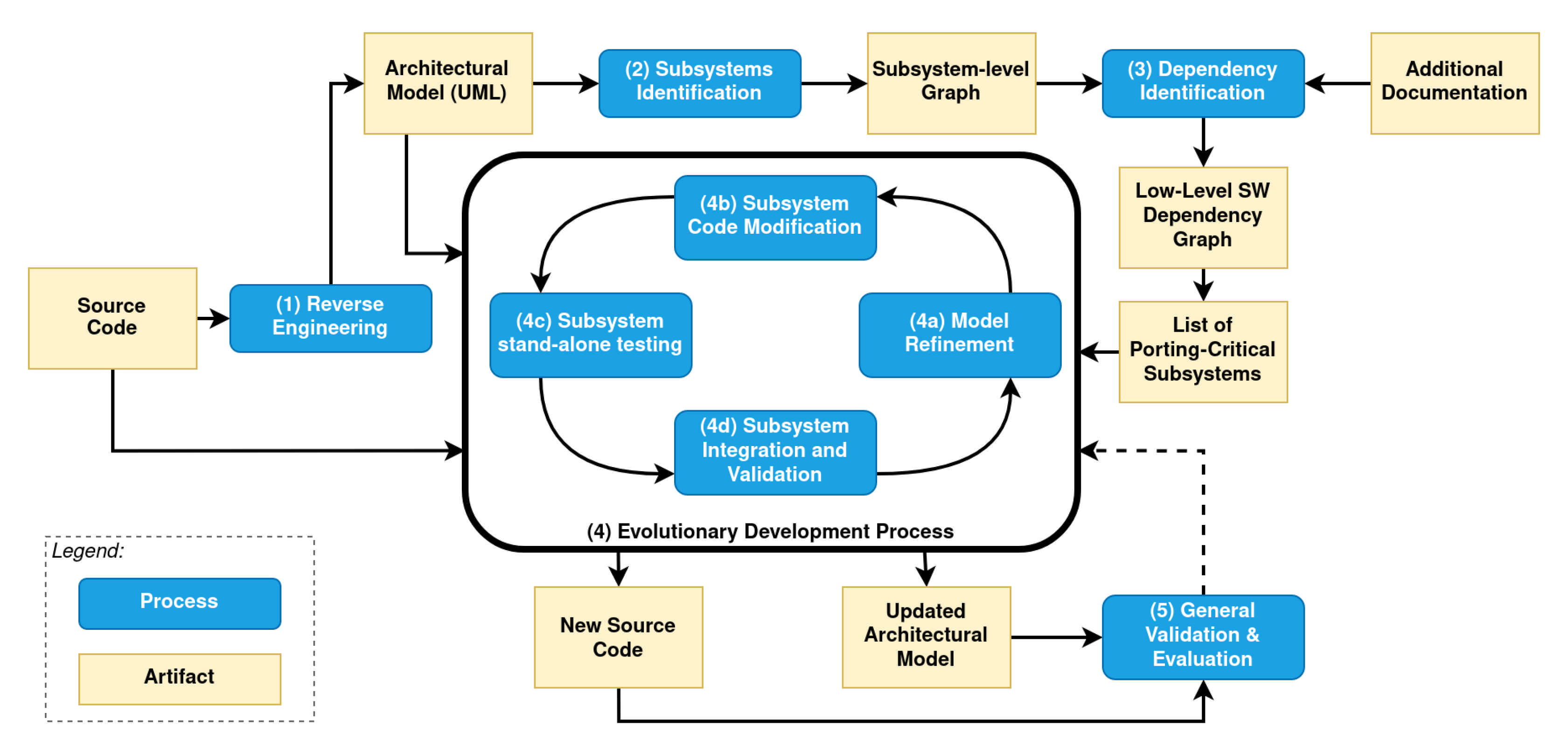
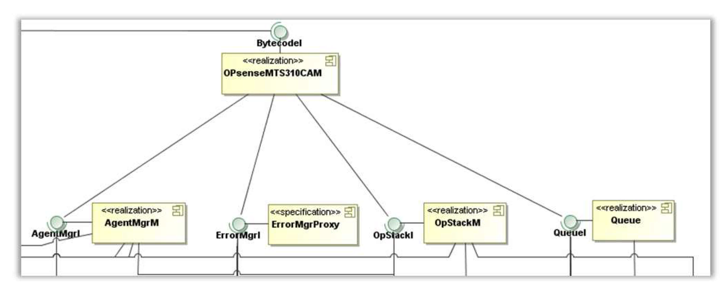
  • Reverse Engineering of the available source code of the target application. An architectural model is obtained that describes its software architecture by using the standard UML description language. This step is not completely automated since there could not be any toolkit available for retrieving full-featured UML diagrams that work directly on the source programming language (e.g., for low-level code or platform-specific languages). Even if the language in which the application is written is not an object-based language, we adopted UML as it is considered a suitable modeling language to describe software architectures; hence, it is adequate for our aim.
  • Subsystems identification. The models obtained in (1) are classified by grouping the components based on their high level functionality. We refer to these groups as the subsystems. This step is very important in big applications, since it helps developers reduce the analysis surface and focus on functionality-oriented porting process. The output of this step is a subsystem-level graph.
  • Dependency identification. The subsystem-level graph is filtered out to identify the dependency of the target application on the lower-level software layers. This step leads to the identification of those subsystems which are porting-critical. In other words, these are the subsystems that contain components that are tightly coupled with low-level software layers and may have the major impact on the porting procedures. To complete this step, it is necessary to explore the available documentation of the application, of the low-level software layers and of the hardware platform of interests (if any).
  • Evolutionary Development Process. This process takes as input the application source code, its architectural model and the list of porting-critical subsystems to produce the architectural model and the source code of the new version of the target application. It consists of multiple iterations of the following four steps, which are interleaved rather than separated, with rapid feedback across activities:
    4a.
    Model Refinement;
    4b.
    Subsystem Code Modification;
    4c.
    Subsystem Stand-alone Testing; and
    4d.
    Subsystem Integration/Validation.
    The process is repeated for every subsystem and ends when the source-code and the architectural models of all considered subsystems are validated and integrated.
  • General Validation & Evaluation. A general application-wise validation step is conducted. This step ensures that the ported application can be used with all its features in place of the old version. If the validation is successful, the application is evaluated in terms of performance gain/loss, memory occupation, or other relevant metrics. If not, the Evolutionary Development Process is started again to refine the models and update the source code. We define a set of metrics to evaluate the porting results, the improvements, and the software quality, which have been measured and compared.
The artifacts obtained at the completion of each step of our procedure are summarized in Table 3.

4. Agilla as the Porting Use Case

In order to validate the proposed approach in the context of WSN software application, we selected the TinyOS-based MW Agilla. Middleware comparisons provided in the literature, e.g., References [31,32], show that the Agilla MW [27] is the most suitable to be adopted and extended for future projects. From Table 2, we see that Agilla presents better characteristics than others in terms of multitasking and number of supported platforms, that are mandatory for a wider usage of it in several contexts. In addition, Agilla MW has a wide literature coverage and has been also selected to be exploited in two European research projects (VISION project [18] and SafeCOP project [19,33]).
Agilla is an MAMW; hence, it can create, substitute, and destroy agents at run-time. In Agilla, a new paradigm for programming can be used. Applications here are special programs, referred to as mobile agents, that can migrate their code and state from one node to another while executing.
Agilla guarantees a high degree of reconfigurability (i.e., agents can be injected, moved, cloned, and replaced, and every physical node can run multiple agents at a time) and reliability (i.e., if an agent crashes, it does not affect the functionality of the hosting WSN node, nor the other agents running on it). In addition, since the deployment of the agents (i.e., the application) is dynamic, there is the possibility to dynamically create and distribute agents to fit the specific context requirements. For example, by injecting a selected set of agents, it is possible to deploy an energy-aware application or to increase the WSN overall security (The Context-Awareness, Energy-Awareness, and WSN Security are the topics we are currently working on. See Section 7 for related future works).
Finally, we successfully adopted Agilla in many contexts (e.g., Reference [18]) during our research activities in WSN and in mobile agent middleware domain.
Unfortunately, in recent times, the heterogeneity of the contributions to TinyOS pushed the main TinyOS developers to re-design and refactor TinyOS to improve its stability and overall quality. This process gave birth to the second (and current) major stable release TinyOS 2.x. However, the compatibility with the older version of TinyOS was broken. Developers who wish to restore their application functionality have to manually perform the porting of the application source code in order to adhere to the new TinyOS 2.x interfaces.
Unfortunately, this was also the case for Agilla, which, with the new release of TinyOS (v2.x), was stopped being compilable with TinyOS libraries and drivers for the WSN hardware platform we were working on, i.e., the Memsic MICAz. With the new version of TinyOS, Agilla cannot be compiled successfully; thus, it cannot benefit from the new introduced features nor support new enabled platforms and protocol support introduced in TinyOS 2.x.
To overcome this problem, we decided to make a porting of Agilla from TinyOS 1.x to TinyOS 2.x. This operation was challenging for several reasons; for example, Agilla architecture and code were not well documented.
In this section, we extend our work presented in Reference [5], better describing the Agilla porting we made. We validate our porting approach on a real-world embedded software application, i.e., Agilla, and make it evolve into a new version that takes full advantage of the new features and supported platforms.

4.1. STEP (1): Agilla Reverse-Engineering
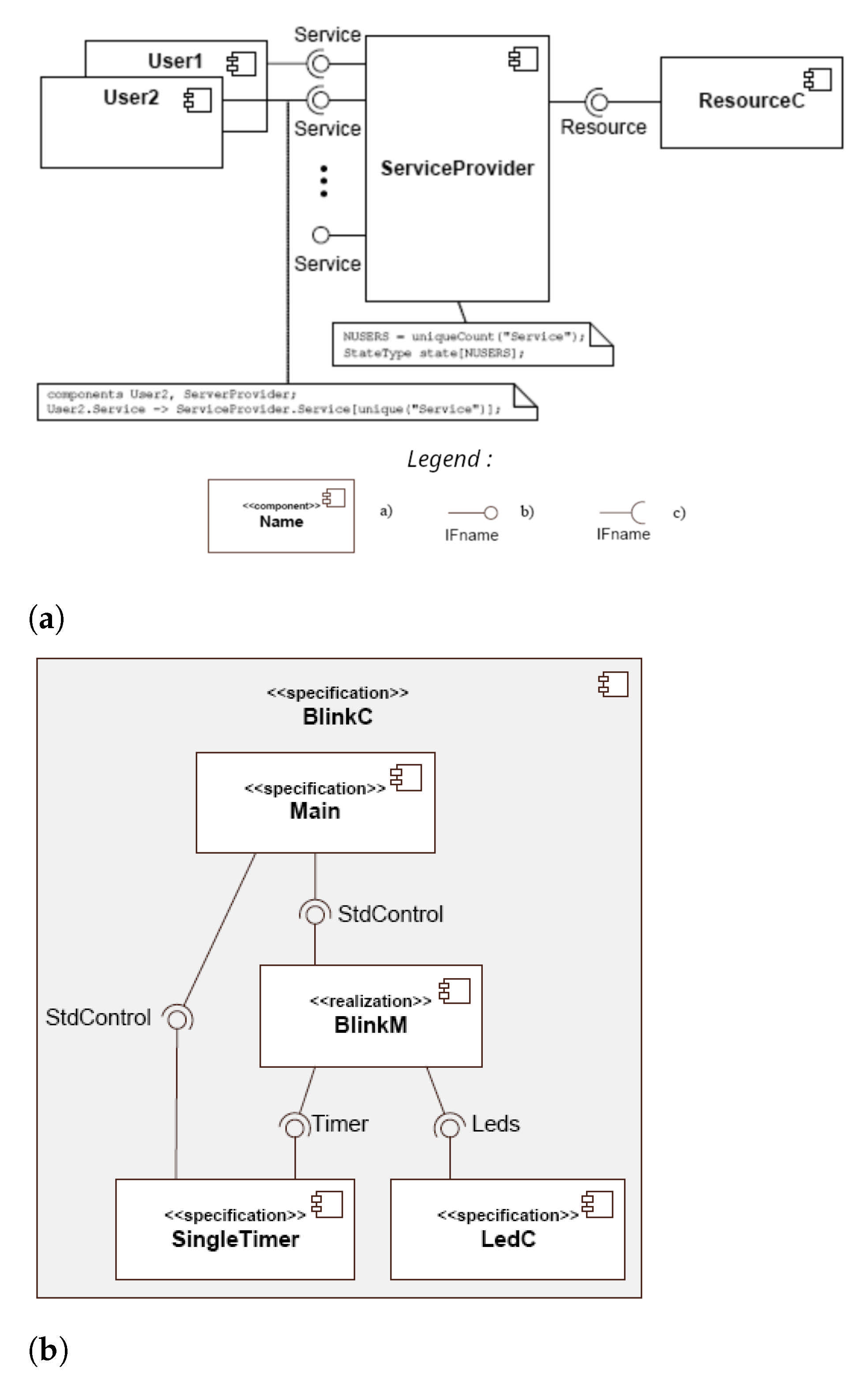
Following  Figure 2, the application of the proposed approach starts with the reverse-engineering step. The reverse-engineering analysis of the available source-code of the application provides an abstract and (possibly) standardized architectural model that helps developers to understand the application’s features and behavior. Most important, such a model gives a dynamic support tool for the subsequent steps of our approach, and it is useful for the future maintainability of the application and the provision of further improvements.
In the following, we focus on our test case application, i.e., Agilla, by first introducing the context-specific UML notations used, then the specific tool provided by TinyOS to create the hierarchical component graph of Agilla, and, finally, the actual UML modeling.

4.1.1. UML Notation

A typical TinyOS-based application consists of a combination of components connected together by interfaces. A component consists of a module, which contains the actual source code and a configuration, which contains the wirings that are the descriptions of the interfaces realized by the component and those required to implement the component’s functionality. In this context, standard UML Component Diagrams, shown in  Figure 3a, fit perfectly the role for modeling TinyOS-based applications.
The description provided by the preliminary UML Component Diagram is enhanced using some UML stereotypes, as shown in Figure 3b. For instance, the realization and specification stereotypes can be used to distinguish component configurations from modules.

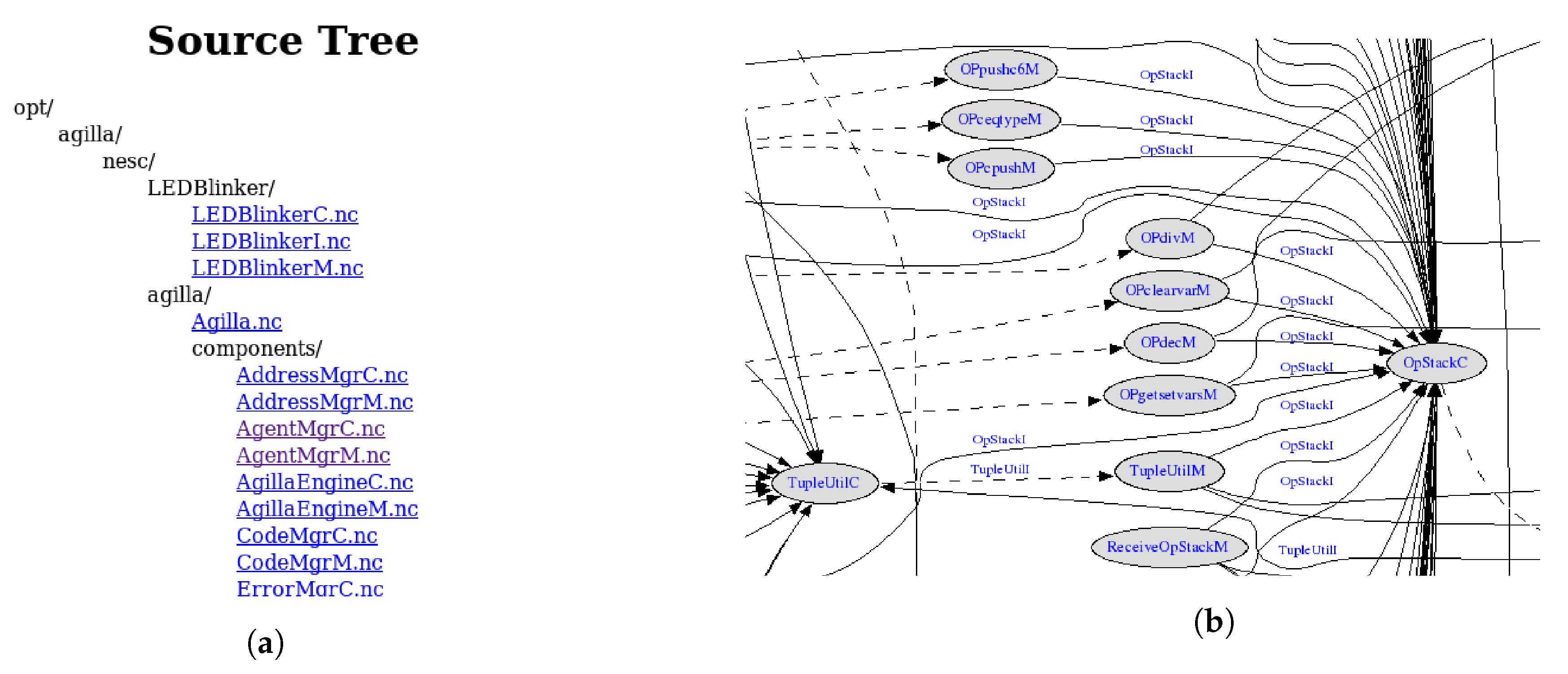
4.1.2. Agilla Component Graph

To simplify the description of large systems in UML notation, we propose to focus on the description of every component hierarchy of the application (as shown in  Figure 3b), rather than of every single component. This way, we may retrieve diagrams at different levels of granularity, e.g., from system-level diagrams to component level diagrams.
Hence, we enumerate and identify component hierarchies in Agilla from its source code. In TinyOS-based applications, all components are usually small and arranged in many layers, in a way that each component provides only a small abstraction increase.
Identifying hierarchies and navigating them could be very tedious with common editing tools. A quick way to visualize and navigate the components hierarchies is to use the nesdoc utility included in TinyOS. This tool automatically generates HTML source-code documentation for components and a graph representation of their hierarchy (using the GraphViz library [34]. From here on, we will refer to the nesdoc output as the Component Graph.
With this kind of information, along with the full UML-compliant Component Diagram we aim to retrieve, it is possible to easily locate and focus on a target set of components of interest.
In  Figure 4a,b, two pieces of nesdoc output are shown. As depicted in  Figure 4a, Agilla uses a specific file name syntax to distinguish modules (file name ending with “M”) and configurations (ending with “C”). In  Figure 4a, the wirings between components and interfaces are shown as arrows. Here, wirings can be a straight full line or a dashed line. In the first case, the interface shown above the arrow is requested to the pointed component. Instead, the dashed line indicates that the interface’s request or use is forwarded to the pointed component.

4.1.3. MagicDraw and Agilla UML Modeling

There are numerous tools available for creating UML component diagrams. However, TinyOS-based application are written in the NesC programming language [17], and only a few of these tools return a clean UML Component Diagram from the NesC source code of a TinyOS-based application. We use MagicDraw software to retrieve a preliminary standard UML model by means of MagicDraw modeling software [35].
By applying MagicDraw to the Agilla source code, we generate a standard UML component diagram describing both Agilla and the TinyOS components used by it. Then, based on the nesdoc-generated components graph, we perform an initial manual refinement of the obtained raw model, adding component’s hierarchy information and fixing some TinyOS components’ wirings caused by the NesC language features not completely supported by MagicDraw.
An example of the resulting Component Diagram, obtained with MagicDraw and enhanced with the Component Graph from nesdoc and some manually-introduced improvements, is shown in  Figure 4a.
The UML Component Diagram obtained in the first step is complete and offers a description of Agilla down to the components and hierarchies relations.

4.2. STEP (2): Agilla’s Subsystem Identification

The second step (Subsystem Identification) aims at creating an additional, coarse-grained model from the starting UML Component Diagram to highlight the logical group of cohesive components (and components hierarchies) considering the features they mean to provide in the overall application. We call such groups of components the subsystems of Agilla.

4.3. STEP (3): Agilla’s Dependency Identification

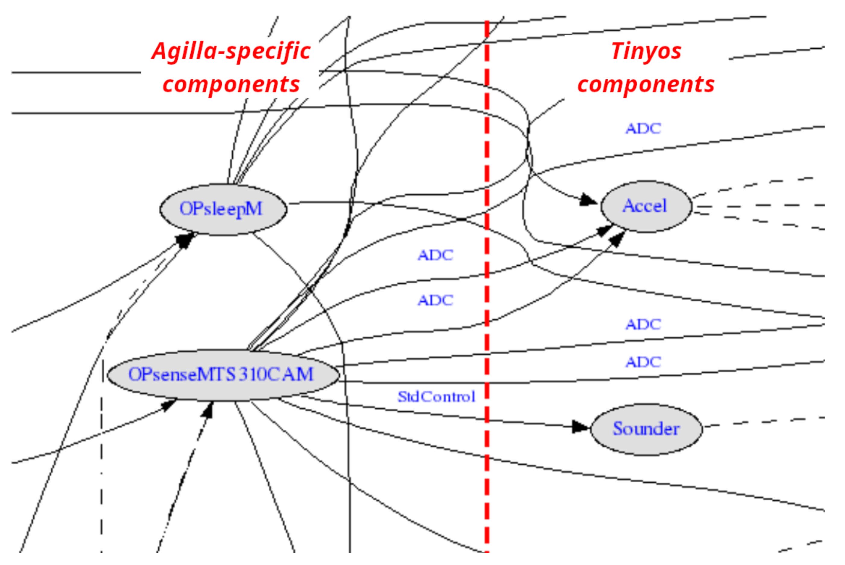
4.3.1. Agilla vs. TinyOS Dependency Analysis

This step aims at analyzing the dependency of the Agilla application and identifying which components need to be reworked for the porting. Any additional available documentation on the target application and on the changes that affected the lower-level software can provide valuable information to developers. The changes introduced in TinyOS from version to version are documented the TinyOS Enhancement Proposals (TEPs) [36]. By reading the TEPs, we identify and track almost all the changes introduced in TinyOS 2.x and determine the impact on Agilla’s subsystems.
After the dependency analysis, we refine further the models (both the UML Component Diagram and the Component Graph), pruning out the unused TinyOS components and adding additional descriptions on the Agilla components to include information (from the TEPs) useful for the next steps.
The pruning of the unnecessary components allows us to draw a separation line ( Figure 5) to divide the Component Graph (and, as a consequence, the UML Component Diagram) in two parts: the Agilla Graph and the TinyOS-Graph, which is out of the scope of this paper and will not be considered in the next steps.
This separation-line has also indirectly identified all the Agilla components standing on the border (i.e., all the components using/providing interfaces from/to TinyOS core components).

4.3.2. Porting-Critical Subsystem Analysis

These components are referred to as critical components and are identified through a further analysis of the subsystem-level component graph. All identified subsystems are logically divided in a set of subsystems which are low-coupled with TinyOS and a set of subsystems which are highly coupled; the subsystems in the latter set are the critical-subsystems and represent the Agilla’s subsystems which are, directly or indirectly, dependant on the architecture of TinyOS.
In the following analysis, we focus on the critical-subsystems since focusing only on the contained components could lead to recursive component-to-component analysis and refactoring (in general, a modification on the interface used/implemented by a component would lead to the modification to other (up to all) connected components. This is particularly true for Agilla critical-components, since they are tightly coupled both with other Agilla components and the underlying TinyOS components.).

4.3.3. Selected Agilla Critical-Subsystems

The critical-subsystems we logically derived from the analysis in Section 4.3 are the following:
  • The Hardware-interface subsystem;
  • The Agent-management subsystem;
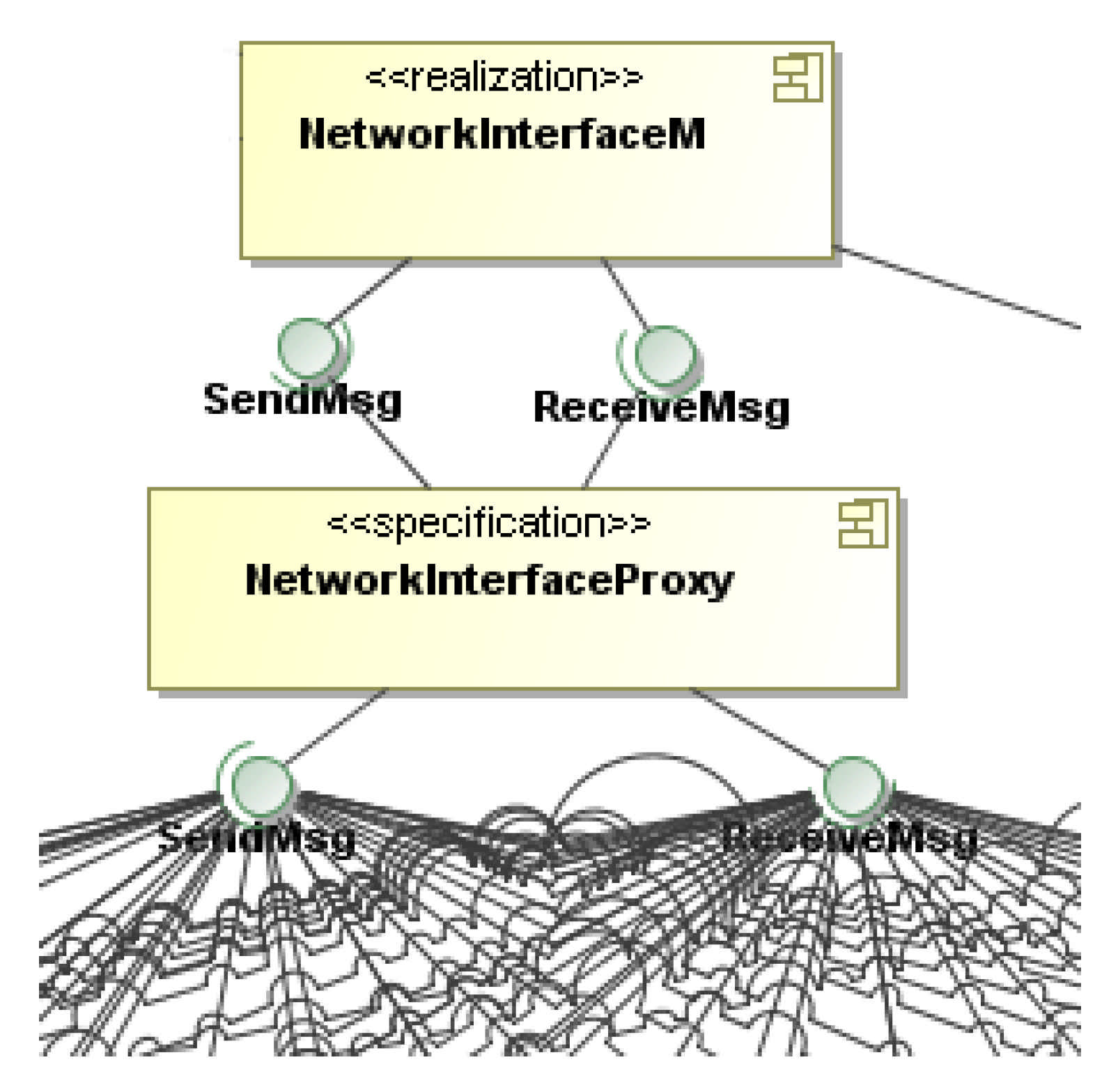
  • The Networking subsystem.
We define the Hardware-interface subsystem as the subsystem which contains the critical-components which deal with the low-level, hardware-related features, such as accessing Input/Output ports (GPIO), ADCs, and sensor interfaces. From the porting point-of-view, this is a key subsystem since it requires a full compliance with TinyOS hardware-abstraction mechanisms to allow Agilla to work properly. An important example is OPsenseMTS310CAC, which manages all the sensor macro-instructions for the sensorboard MTS310 (Figure 6). This component is very important because sensing capabilities are mandatory and the MTS310 is one of the most used and feature-rich sensorboard compatible with the MICAz platform (our target mote platform).
A second critical subsystem is the group of components involved in providing the peculiar Agilla mobile-agents functionalities, the Agent management subsystem. This subsystem gathers the components involved in creating new agents, managing their resources, scheduling, and executing them using a Round-Robin execution policy to simulate multi-agent execution. The criticality of this subsystem is due to the evolution of the TinyOS primitives for lightweight multi-tasking (e.g., the new task keyword), booting, event scheduling, and the new components for using common data structure with hardware independent representation and management.
The most notable component we found in this subsystem is AgillaEngineM. This component is itself one of the most critical component for the porting of Agilla, since it provides, as the name suggests, all the basic functionalities of agents, often delegating part of them to other components, which makes it very high-coupled with any other component in this subsystem.
Finally, the last porting-critical subsystem we identified is the Networking subsystem. We place in this subsystem all the components involved in data and agents communications. In particular, we discovered that most of the components in this subsystem use the underlying TinyOS primitives to achieve the desired operation. The new version of TinyOS impacted all these components by introducing the so-called Active Message data structure as mean to achieve all the wired and wireless communications in an hardware-independent way. All the previous communication mechanisms (e.g., SendMsg and ReceiveMsg) are deprecated in TinyOS 2.x.
Due to this change, all the components that need or provide communication facilities from TinyOS needs to be modified to work on top of TinyOS 2.x Active Message-based abstraction layer [37].
One of its most important component is NetworkInterfaceM, which is the façade component used to send and receive messages of different types (e.g., from simple data messages to the agent code, data structures, and signaling messages).
Our analysis (Figure 7) shows that the Networking subsystem and the components related to NetworkInterfaceM have a very high dependency.
From a software architecture point-of-view, this subsystem has an important issue: it is a single point of failure, since an error or crash in a component in this subsystem is likely to compromise the whole Agilla communication functionality (affecting all other running agents). This issue is eliminated during the Evolution Development Process, i.e., as a further improvement, we reworked the subsystem to enhance its resilience.

4.4. STEP (4): Agilla Evolutionary Development Process

The evolutionary development process returns a working (i.e., compilable and runnable) Agilla on TinyOS 2.x (Agilla 2). It is articulated in four steps:
  • Model refinement— Focusing on the subsystem components, the information quality and quantity on the UML Component Diagram and Component Graph models are refined and enhanced, by adding information about, e.g., where the components are located, which algorithms and data structure use to achieve their functionalities, etc. The refined subsystem models contain useful information for the developers to progress in the subsequent step of source code modification. Moreover, as said previously, in this step, developers can decide to improve some aspects of the architecture of the subsystems.
  • Subsystem code modifications—Using the original model and the refined model as supports, the original source code is analyzed and reworked. At this stage, it is needed to re-analyze carefully the TEPs to find the changes introduced in TinyOS 2.x. The TEPs can be found in every TinyOS distribution in various formats (e.g., txt, pdf, html). With this information from the TEPs, it is possible to rework most of the code of the porting-critical subsystems with few process iterations (in the range from one to four).
  • Subsystem stand-alone testing— This step is intended to create a stand-alone testing environment (testbeds) of the correct operation of the subsystems, with no need of compiling the whole application. This step helps developers to quickly check and fix problems from the previous step, potentially reducing the number of issues that may appear after the integration of the reworked subsystem in the application. In addition, by testing only the target subsystem in its testbed, developers can focus on the subsystem functionalities, reducing the quantity of code to review/test and the time required to perform such operations. The creation of the testbeds for Agilla consisted in creating new, small, TinyOS 2.x applications which include only the target subsystem and some basic boot code.
  • Subsystem integration & validation—The final step of each iteration in the process consists of the integration of the subsystem into the application. Since the interfaces used and provided by the target subsystem may have been modified, in this phase, developers have to discover and list inter-subsystem problems which can be handled in a subsequent iteration of the process of the same subsystem. An optional activity can be performed during the subsystem integration step: testbeds (created in the previous step) of different subsystems can be enhanced and combined together to create an ”incremental” testbed which includes, piece by piece, the reworked subsystems. This way, it is possible to both create progressively an application-wise testbed and incrementally validate the subsystems.

4.5. STEP (5): General Validation & Evaluation

After the execution of the Evolutionary Development Process, a runnable version of the ported application is ready. The final step of our model-based approach consists of an overall validation which ensures that the new version of the application can actually replace the old version.
In our case, we compile the ported Agilla (Agilla 2) by exploiting the TinyOS make system, which automatically launch the current cross-compiling tools to produce the final programmable binary file. A first validation check can be performed right after compilation, by analyzing the compilation results against the capabilities of the target platform. In this sense, we compare the compiled Agilla 2 storage requirements (obtained directly from the compilation phase) against the memory storage available in the target mote hardware (MICAz). We obtain an occupation of 56 KB of ROM (code) and 3.6 KB of RAM (data), which are compatible with the MICAz mote storage limits (128 KB of ROM and 4 KB of RAM). After the correct compilation of Agilla 2, we successfully compile the AgillaAgentInjector Java GUI application used to inject the agents into the motes.
The final validation step is to check the correctness of Agilla 2 at run-time. The goal is to verify whether an agent-based application runs properly on Agilla 2, exploiting all available features, such as communications, sensor readings, and migration of agents.
The validation is then carried out over two reference scenarios. The first validation scenario, shown in  Figure 8, consists of two MICAz nodes, marked as Mote 0 and Mote 1. A programming board MIB510 is connected to the gateway (a PC) via wired serial connection, and to the Mote 0. Mote 1 mounts the MTS310 sensorboard and, being away, is remotely connected to Mote 0. Through the sense instruction [38]), which takes as input the type of sensor to read from, we get the sensor readings.
The validation is performed by the MICAz with Agilla 2 installed and a proper agent injected through the AgentInjector, which starts to retrieve data and forwards them to the PC. The AgentInjector interface and its Oscilloscope component on the PC shows the expected waveform related to collected data. Among the available agent-based application in Agilla, Oscilloscope [39] is one of the most meaningful: it offers a oscilloscope-like visualization of the sensor data retrieved from all the mote in the WSN versus time, visualizing a waveform.
The second scenario targets the development of an Android application to show on a smartphone display the data received from an Agilla 2 agent. The Mote 0 is connected to the MIB510 programming board, connected to a PC where the data from the mote are collected and forwarded to an USB or Wi-Fi connected Android smartphone by a basic forwarder application.
In  Figure 9 the graphs of collected data are shown both in the legacy host interface and the smartphone application.

5. Agilla 2: Quality and Performance Analysis

The ported version of Agilla (Agilla 2) supports the Active Messages and can communicate (both via radio and via serial ports) seamlessly. In addition, Agilla 2 gained:
  • a larger compatibility with new WSN mote hardware platforms (e.g., IRIS motes);
  • an increased stability, thanks to the reworks of problematic hierarchies, e.g., the removal of the single-point-of-failure of the NetworkInterface component;
  • increased mantainability, thanks to the new available models, which can be used both to maintain Agilla 2 code and as support tool to navigate and correct problems in the code.
In this section, we discuss and compare the ported version of Agilla and its original version in terms of software quality, performance, and maintainability.
In addition, from an higher point of view, our objective has been to determine whether the cost of the model-based porting approach is worth the application of such methodology.

5.1. Metrics

In order to estimate the cost of performing the porting, i.e., the differences in terms of performance and memory footprints between the original Agilla (on top of TinyOS 1.x) and Agilla 2 (on top of TinyOS 2.x), we define the set of metrics described in Table 4.
Then, the original Agilla and Agilla 2 source code have been instrumented, compiled and investigated to retrieve such metrics:
  • Source code lines (nesCLoC) are retrieved by summing the lines of each Agilla component NesC source file (excluding TinyOS components). Such a sum has been obtained using the standard UNIX command wc-l.
  • The resulting C source code lines can be retrieved by counting the lines of the app.c file, which is generated by the NesC trans-compiler upon compilation. Although a raw measure of the source code lines has no strong meaning, it is useful to consider the ratio between the two metrics (i.e., Line of Codes Ratio):
    L o C R a t i o : = C L o C n e s C L o C .
    The resulting value is higher when few lines of NesC code generate a high number of C source code lines. This is a good indication of the expressivity of the NesC source code.
  • The storage occupation (both for RAM and ROM storage) is computed directly upon a successful compilation of Agilla/Agilla 2. As in any embedded system, the desired value for those two metrics is as little as possible. In the RAM case, the storage occupation takes into account only data allocated on start. Dynamically allocated data is not included, although it can be neglected since Agilla and, in general, software applications for embedded systems, do not include a dinamic memory allocator and use only pre-allocated data.
  • The components fan-in/fan-out metric is the number of relations between provided and used interfaces in the components. The method we applied to evaluate this metric is to use the UML Component Diagram to find the critical components and counting the total number of provided interfaces and the total number of (unique) used interfaces. This metric gives an indication on how many relations have to be broken in order to refactor the critical components of Agilla.
  • A similar metric is the dependency of Agilla and its underlying TinyOS version. We define this metric as the number of relations between the Agilla components and the TinyOS components. We retrieve such number by using the Component Graph. A loose dependency is obviously preferable.
  • Finally, we take into account the quality of the documentation in the Agilla/Agilla 2 source code.
    We use two metrics: the comment-ratio and the artifact ratio, definitions of which can be found in Reference [4]. Apart from the source code, we also consider (for Agilla 2) the documentation created during the porting operations.

5.2. Results

Table 5 summarizes the values retrieved for the defined metrics. The combination of TinyOS 2.x and Agilla 2 has a very light degradation (~2% ) in ROM memory occupation. Since the Flash/ROM storage is used mostly for code and constant data, our investigation (in which we analyzed the cross-compiled the ELF binary image with standard UNIX tools to retrieve the size of each exported symbol) led to the conclusion that the cause of the larger impact on ROM can be found both in the additional code added in Agilla 2 and in the new code found in TinyOS 2.x. The RAM occupation shows, instead, an higher level of degradation. In this case, the cause is mainly due to the TinyOS 2.x additional data allocated, for example, to support some of the new TinyOS 2.x features.
The LoCRatio metric, instead, shows a steep improvement. Since this metric can be directly related to the level of expressivity of the NesC source code (i.e., less NesC code produces more C code), this could mean that the combination of TinyOS 2.x and Agilla 2 has a more expressive code. In other terms, the abstractions provided both in TinyOS 2.x and in the internal components of Agilla 2 allows developers to write fewer lines in a “higher level” NesC code, hiding the complexity and the heterogeneity of the hardware/software platforms. This is an important result from the software quality, since less code is easier to maintain and future-proof.
To confirm the evolution in terms of software quality, the CritFanInOut and the Dependency metrics show an improvement in terms of relations between the internal Agilla 2 components. Less relations, in this case, means that components are less coupled and more independent one another. This is a relevant improvement, since, from the maintenance point-of-view, loosely-coupled components are easier to be replaced or modified without endanger the whole application functionality.
Finally, we can derive the conclusion that the overall TinyOS structure has improved and less user-written code is required to develop applications. This aspect is perfectly caught by the Agilla 2 experience: the internal structure of Agilla is simplified and improved, with a consequent improvement on the maintainability of Agilla 2 itself.

6. Agilla Improvements

During the porting activities, we had the possibility to enhance Agilla by improving features or adding new ones. Such operations required a deep knowledge of Agilla source code and its inner mechanisms in order to improve parts of it on-the-fly to better suite the new requirements and gain various advantages, in terms of software quality (e.g., performance, energy consumption, etc.). We use this knowledge to model the architecture of Agilla and its inter-dependency with TinyOS 1.x by using UML and graphs. The obtained models are currently not available in Agilla’s official documentation. Nevertheless, they are useful for future Agilla’s maintenance and will be made available to the scientific community.
In order to test the effectiveness of our approach in real conditions, we decided to further validate the model-based approach and its results by introducing additional requirements in Agilla 2. In particular, we decided to add Energy-Awareness in Agilla 2 agents in the form of new features to be introduced in the Agilla 2 code resulting from the application of our approach.

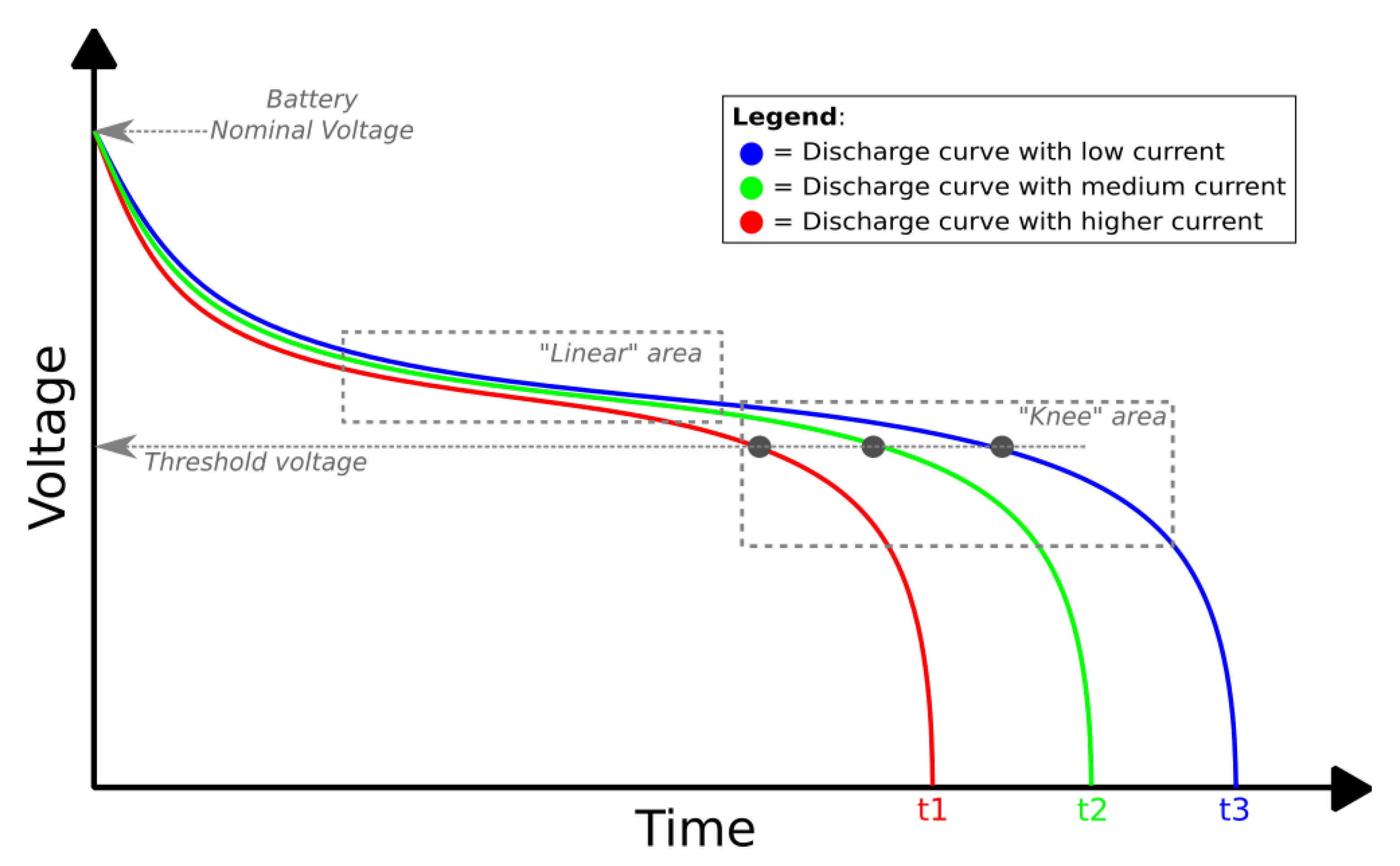
6.1. Energy Consumption and WSN Node Lifetime Considerations

We define the lifetime of a WSN node to be, given the average energy consumption of a node, the amount of time for which the current set of batteries can keep the node powered up, while making it work as intended. The intended behavior of a WSN node is, obviously, derived by the software running on the node, in our case, Agilla 2. However, when electrical parameters applied to the node (e.g., required input voltage) do not meet the platform electrical specifications, the results of the hardware platform computations cannot be trusted anymore. In this sense, the lifetime of a WSN node is considered ended when any of some basic electrical requirements (minimum input voltage and maximum required current) can be satisfied by the current state of the batteries.
The energy consumption of a node is measured as the amount of energy currently drawn from the batteries of a node. Although energy (according to the SI) is measured in Joules, alternative measurement units are commonly adopted. In particular, when the supply voltage can be considered a constant value, the Ampere-Hour and its sub-units (i.e., milliAmpere-hour, mAh) are adopted. So, in order to measure the power consumption (i.e., the energy consumption over time) of a node, the intended (constant) voltage and the average electrical current have to be known. In particular, the latter is directly proportional to the consumed energy.
Measuring electrical currents in WSN nodes is a not trivial task. Common current measuring techniques (e.g., shunt resistors, Hall-effect sensors, etc.) usually have either low accuracy or limited range of measurable currents, while a WSN node, depending on its state, could have a very different current drawn, usually ranging from a few μA when (in sleep state) up to hundreds of mA (when full powered on and while using the radio transceiver).
One last issue in measuring energy consumption on WSN motes is related to the specific behavior of batteries. Such a behavior is characterized by the so-called Battery Discharge Curve, which is a representation of the provided output voltage ws. time when battery is discharging with a given current and temperature [40]. An example of these curves is shown in  Figure 10.

6.2. New Instruction: battery

By considering the discharge curve in  Figure 10, it is possible to simplify the approach to the energy consumption measurement by avoiding consideration of the drawn electrical current, while making a mapping between the expected and the actual battery output voltage following a “golden” discharge curve, selected to best approximate the discharge behavior of the adopted batteries. This approach lacks of the accuracy of a real current and energy measurement but requires no additional hardware and is extremely fast, having, at the same time, no side effects on consumption (e.g., using other approaches could require a portion of energy to perform the measurement of the same).
In order to provide Agilla 2 with a run-time primitive to estimate the WSN node lifetime, we adopted the aforementioned approach and decided to add the battery instruction in the Agilla 2 ISA. This instruction allows agents to retrieve a raw indication the remaining lifetime of a WSN node. This value can then be used to perform energy-driven choices [18,41].
Adding a new instruction to an already-complex application while maintaining a clean and flexible architecture in embedded system applications is, in general, a non-trivial issue. However, thanks to the proposed model-based approach, we have a clear understanding of which are the subsystems and components involved in adding a new instruction, how those components affect the overall software architecture, and which is the preferred way to ensure a minimal development effort to have the new instruction implemented with a minimal dependency on the underlying software layers.
As a result, Agilla 2 agents can now use the battery instruction in their code to retrieve a raw estimation of the WSN node lifetime in which they are currently under execution. So, with such an information, agents could, for example, decide to adopt different behaviors or just clone/move to other WSN nodes before the full depletion of the node batteries occurs. This approach has been used in Reference [18]: by considering the shape of the Lithium-Ion batteries discharge curve, a threshold voltage has been defined to be located before the knee of the curve (as shown in  Figure 10), enough to give agents enough time to perform reactions.
Details on the instruction. The battery instruction is implemented as two de-coupled modules. A first module (VoltageC) is tight to the TinyOS interfaces and provides a platform-independent interface to retrieve a representation of voltage (in terms of ADC units) of the batteries via a specific ADC channel. This value is converted in an actual voltage measurement by the second module (OPBattery), which also takes care of providing the requirements necessary in Agilla 2 to insert a new instruction in its ISA. To convert the ADC measurement from VoltageC, this module adopts the following formula:
V o l t a g e = 10 × [ ( 1100 × 1024 ) / v a l u e ] 36 .
The converted value is pushed in the Agilla 2 operand stack, so that it can be used by the next agent instructions.
Results. Thanks to the model-based approach, the impact of the instruction’s modules in the overall Agilla 2 is negligible: the two modules are separated, and future adaptations (e.g., in the case of future TinyOS versions) require only to change one of the two modules. In addition, in case the new instruction is not useful anymore, it can be enabled or disabled with a compilation-time switch and no additional changes to code.

7. Conclusions

In this paper, we proposed a novel model-based approach to perform the porting of software applications in the context of embedded systems, and, in particular, of WSN. Our approach allows developers to rework an application by extracting preliminary software architecture models from the source code of the original application and then refining, filtering, and using such models in an evolutionary software process. This process produces, as an output, the new source code for the application and the updated models. The models obtained can be used as effective support tools for future maintainability tasks or to add new features to the application.
We tested our approach by porting the very popular WSN MAMW Agilla to the most recent release of TinyOS. The application of the model-based porting to Agilla has shown that not only a working ported application can be obtained with a low effort, but the software architecture and the software quality are also improved during the porting steps. As a result, we obtained Agilla 2: a fully compliant TinyOS 2.x version of the original Agilla, which, beyond the benefits introduced by TinyOS 2.x, gains also better software architecture and documentation (in form of updated models), easier maintainability, and improved performance.
We further validated our approach by introducing a new feature in Agilla 2: a new instruction to provide Agilla 2 agents a raw estimation of the remaining WSN node lifetime, so that is possible to provide energy-awareness to agents and, in general, to WSN agent-based applications.
We plan to improve our model-based technique by considering other important aspects for embedded systems software. For example, like e.g., the security of embedded applications. Our model-based approach could consider, at various stages, the level of robustness and resilience against attacks of different software architecture in order to provide a good trade-off.
The result obtained by the application of our model-based porting approach, Agilla 2, is itself part of some of our current works. We plan to further extend Agilla 2 to add new features (e.g., new instructions, new paradigms) and to provide Agilla 2 with context-awareness capabilities to make it a complete dynamic solution for monitoring applications deployed on WSNs.

Author Contributions

Conceptualization, A.D.M. and D.C.; methodology, A.D.M., D.C. and L.P.; software, W.T., M.S., and L.P.; formal analisys, A.D.M.; investigation, A.D.M. and L.P.; writing—original draft preparation, A.D.M., W.T. and M.S.; writing—review and editing, W.T., D.C., M.S. and L.P.; visualization, W.T.; supervision, A.D.M., D.C., L.P.; project administration, D.C. and L.P.; funding acquisition, D.C. and L.P. All authors have read and agreed to the published version of the manuscript.

Funding

This research was partially funded by VISION FP7-IDEAS-ERC grant number 240555 and SAFECOP ECSEL JU grant number 692529-2.

Informed Consent Statement

Not applicable.

Data Availability Statement

Data sharing is not applicable to this article.

Conflicts of Interest

The authors declare no conflict of interest.

References

  1. Levis, P. TinyOS: An operating system for sensor networks. In Ambient Intelligence; Springer: Berlin/Heidelberg, Germany, 2005. [Google Scholar]
  2. Dunkels, A.; Gronvall, B.; Voigt, T. Contiki—A Lightweight and Flexible Operating System for Tiny Networked Sensors. In Proceedings of the 29th Annual IEEE International Conference on Local Computer Networks, Dallas, TX, USA, 11–13 October 2004; pp. 455–462. [Google Scholar] [CrossRef]
  3. Baccelli, E.; Gündoğan, C.; Hahm, O.; Kietzmann, P.; Lenders, M.S.; Petersen, H.; Schleiser, K.; Schmidt, T.C.; Wählisch, M. RIOT: An Open Source Operating System for Low-End Embedded Devices in the IoT. IEEE Internet Things J. 2018, 5, 4428–4440. [Google Scholar] [CrossRef]
  4. Aghajani, E.; Nagy, C.; Vega-Márquez, O.L.; Linares-Vásquez, M.; Moreno, L.; Bavota, G.; Lanza, M. Software Documentation Issues Unveiled. In Proceedings of the 2019 IEEE/ACM 41st International Conference on Software Engineering (ICSE), Montreal, QC, Canada, 25–31 May 2019; pp. 1199–1210. [Google Scholar] [CrossRef]
  5. Corradetti, L.; Gregori, D.; Marchesani, S.; Pomante, L.; Santic, M.; Tiberti, W. A renovated mobile agents middleware for WSN porting of Agilla to the TinyOS 2.x platform. In Proceedings of the 2nd International Forum on Research and Technologies for Society and Industry Leveraging a Better Tomorrow, Bologna, Italy, 7–9 September 2016; pp. 1–5. [Google Scholar]
  6. Agilla2 Repository. Available online: https://github.com/luigi-pomante/Agilla2 (accessed on 20 February 2021).
  7. IEEE Standard Test Access Port and Boundary Scan Architecture. IEEE Std 1149.1-2001 2001. 2001, pp. 1–212. Available online: https://0-standards-ieee-org.brum.beds.ac.uk/standard/1149_1-2013.html (accessed on 20 February 2021).
  8. Telosb Platform Datasheet. Available online: http://www2.ece.ohio-state.edu/~bibyk/ee582/telosMote.pdf (accessed on 20 February 2021).
  9. MICAz Platform Datasheet. Available online: http://courses.ece.ubc.ca/494/files/MICAz_Datasheet.pdf (accessed on 20 February 2021).
  10. IRIS platform datasheet. Available online: http://www.nr2.ufpr.br/~adc/documentos/iris_datasheet.pdf (accessed on 20 February 2021).
  11. FreeRTOS requirements. Available online: https://docs.aws.amazon.com/freertos/latest/portingguide/porting-guide.html (accessed on 20 February 2021).
  12. Windows 10 IoT Requirements. Available online: https://docs.microsoft.com/en-us/windows-hardware/design/minimum/minimum-hardware-requirements-overview (accessed on 20 February 2021).
  13. TinyOS Homepage. Available online: http://www.tinyos.net/ (accessed on 20 February 2021).
  14. Contiki OS Homepage. Available online: http://www.contiki-os.org/ (accessed on 20 February 2021).
  15. RIOT OS Homepage. Available online: https://www.riot-os.org/ (accessed on 20 February 2021).
  16. RIOT Support for AVR Platforms. Available online: https://doc.riot-os.org/group__boards__common__atmega.html (accessed on 20 February 2021).
  17. Gay, D. The nesC language: A holistic approach to networked embedded systems. Acm Sigplan Not. 2003, 38, 1–11. [Google Scholar] [CrossRef]
  18. Cassioli, D.; Cortellessa, V.; Marco, A.; Pomante, L. A Successful VISION: Video-oriented UWB based Intelligent Ubiquitous Sensing. In Proceedings of the 8th IEEE Consumer Communications and Networking Conference, Las Vegas, NV, USA, 9–12 January 2011. [Google Scholar]
  19. Agosta, G.; Barenghi, A.; Brandolese, C.; Fornaciari, W.; Pelosi, G.; Delucchi, S.; Massa, M.; Mongelli, M.; Ferrari, E.; Napoletani, L.; et al. V2I Cooperation for Traffic Management with SafeCop. In Proceedings of the 2016 Euromicro Conference on Digital System Design (DSD), Limassol, Cyprus, 31 August–2 September 2016; pp. 621–627. [Google Scholar] [CrossRef]
  20. Lingaraj, K.; Biradar, R.V.; Patil, V.C. A Survey on Middleware Challenges and Approaches for Wireless Sensor Networks. In Proceedings of the 2015 International Conference on Computational Intelligence and Communication Networks (CICN), Jabalpur, India, 12–14 December 2015; pp. 56–60. [Google Scholar] [CrossRef]
  21. Pugliese, M.; Pomante, S. Agent-based scalable design of a cross-layer security framework for wireless sensor networks monitoring applications. In Proceedings of the 2009 International Conference on Ultra Modern Telecommunications & Workshops, St. Petersburg, Russia, 12–14 October 2009. [Google Scholar]
  22. Madden, S.; Franklin, M.; Hellerstein, J.; Hong, W. TinyDB: An Acqusitional Query Processing System for Sensor Networks. ACM Trans. Database Syst. 2005, 30, 122–173. [Google Scholar] [CrossRef] [Green Version]
  23. Pomante, L.; Di Felice, P. WSN and GIS integration for a Cost-Effective Real-Time Monitoring of Landslides on Railway Stations and Lines. In Proceedings of the 2018 IEEE 29th Annual International Symposium on Personal, Indoor and Mobile Radio Communications (PIMRC), Bologna, Italy, 9–12 September 2018; pp. 396–400. [Google Scholar] [CrossRef]
  24. Khan, I.; Belqasmi, F.; Glitho, R.; Crespi, N.; Morrow, M.; Polakos, P. Wireless sensor network virtualization: A survey. IEEE Commun. Surv. Tutor. 2016, 18, 553–576. [Google Scholar] [CrossRef] [Green Version]
  25. Heinzelman, W.; Murphy, A.; Carvalho, H.; Perillo, M. Middleware to support sensor network applications. IEEE Netw. 2004, 18, 6–14. [Google Scholar] [CrossRef]
  26. Kwon, Y.; Sundresh, S.; Mechitov, K.; Agha, G. ActorNet: An Actor Platform for Wireless Sensor Networks. In Proceedings of the 5th International Joint Conference on Autonomous Agents and Multiagent Systems (AAMAS), Hakodate, Japan, 8–12 May 2006; pp. 1297–1300. [Google Scholar]
  27. Fok, C.; Roman, G.; Lu, C. Agilla: A Mobile Agent Middleware for Self-Adaptive Wireless Sensor Networks. ACM Trans. Auton. Adapt. Syst. 2009, 4, 1–26. [Google Scholar] [CrossRef]
  28. Aiello, F.; Fortino, G.; Gravina, R.; Guerrieri, A. MAPS: A mobile Agent Platform for Java Sun SPOTs. In Proceedings of the 3rd International Workshop on Agent Technology for Sensor Networks, Stanford, CA, USA, 9–11 September 2009. [Google Scholar]
  29. Jan, H.; Kolaice, S.; Kolaiciach, T.V. WSageNt: A case study. In Proceedings of the CSE 2010 International Scientific Conference on Computer Science and Engineering, Stará Ľubovňa, Slovakia, 20–22 September 2010; pp. 258–264. [Google Scholar]
  30. Muldoon, C.; Hare, G.; Collier, R.; O’grady, M. Agent Factory Micro Edition: A Framework for Ambient applications. Lect. Notes Comput. Sci. 2006, 3993, 727–734. [Google Scholar]
  31. Wang, M.M.; Cao, J.N.; Li, J.; Sajal, K.D. Middleware for Wireless Sensor Networks: A Survey. J. Comput. Sci. Technol. 2008, 23, 305–326. [Google Scholar] [CrossRef] [Green Version]
  32. Masri, W.; Mammeri, Z. Middleware for Wireless Sensor Networks: A Comparitive analysis. In Proceedings of the IFIP International Conference on Network and Parallel Computing Workshops, Dalian, China, 18–21 September 2007; pp. 349–356. [Google Scholar]
  33. Agneessens, A. Safe cooperative CPS: A V2I traffic management scenario in the SafeCOP project. In Proceedings of the 2016 International Conference on Embedded Computer Systems: Architectures, Modeling and Simulation (SAMOS), Agios Konstantinos, Greece, 17–21 July 2016; pp. 320–327. [Google Scholar]
  34. GraphViz Library and Software. Available online: https://graphviz.org/ (accessed on 20 February 2021).
  35. MagicDraw. Available online: https://www.nomagic.com/products/magicdraw (accessed on 20 February 2021).
  36. TinyOS Enhancement Proposals (TEPs). Available online: https://github.com/tinyos/tinyos-main/tree/master/doc (accessed on 20 February 2021).
  37. Tinyos-Main. Available online: https://github.com/tinyos/tinyos-main/blob/master/doc/txt/tep116.txt (accessed on 20 February 2021).
  38. Agilla Instruction Set Architecture. Available online: http://mobilab.cse.wustl.edu/projects/agilla/isa.html (accessed on 20 February 2021).
  39. Agila. Available online: http://mobilab.cse.wustl.edu/projects/agilla/docs/tutorials/3_obtaining_sensor_data.html (accessed on 20 February 2021).
  40. Discharge Characteristics of Li-ion Batteries. Available online: https://batteryuniversity.com/learn/article/discharge_characteristics_li (accessed on 20 February 2021).
  41. Berardinelli, L.; Di Marco, A.; Pace, S.; Pomante, L.; Tiberti, W. Energy consumption analysis and design of energy-aware WSN agents in fUML. In European Conference on Modelling Foundations and Applications; Springer: Cham, Switzerland, 2015; pp. 1–17. [Google Scholar]
Figure 1. Example Wireless Sensor Network (WSN) mote: the MICAz.
Jsan 10 00020 g001
Figure 2. Model-based porting process.
Jsan 10 00020 g002
Figure 3. UML usage for modeling NesC-based software components. (a) Example: Pattern Service Instance in UML notation. (b) Component UML notation: using stereotypes.
Jsan 10 00020 g003
Figure 4. Agilla: components list and relations between them. (a) List of components and interfaces in Agilla. (b) Components graph from nesdoc.
Jsan 10 00020 g004
Figure 5. Agilla (left) and TinyOS (right) “virtual” component separation line.
Jsan 10 00020 g005
Figure 6. Agilla OPsenseMTS310CAC component model and relation of its required components.
Jsan 10 00020 g006
Figure 7. Agilla NetworkInterfaceM and NetworkInterfaceProxy components relations.
Jsan 10 00020 g007
Figure 8. The adopted validation scenario: a first mote (Mote 0) is connected to the PC via wired serial communication; a second mote (Mote 1) is battery-powered and positioned away from Mote 0, with which communicates via the radio channel.
Jsan 10 00020 g008
Figure 9. Data visualization in the Agilla Oscilloscope application and on USB connected Android smartphone.
Jsan 10 00020 g009
Figure 10. Example of battery discharge curves.
Jsan 10 00020 g010
Table 1. Typical amount of resources for target WSN platforms.
CPU/MCU ArchitectureClock Freq.Instructions Per SecondFlash/ROMRAM
Harvard, 8- or 16-bit16–25 MHz8–16 MIPS32–128 KiB8–10 KiB
Table 2. Agent-based middleware (MW) comparison.
AgillaactorNetMAPSAFMEWSageNt
MigrationYYYYY
MultitaskingYYYYN
Communication Modeltuple spacemessagesmessagesmessagesmessages
Programming Languageproprietary ISAScheme-likeJavaJavaALLL
Agent ModelAssembler-likeFunctionalFinite StateBDIAssembler-like
Machine
Intentional AgentsNNNYN
Sensor PlatformsMica2, MICAz, TelosBMica2Sun SPOTSun SPOTMICAz, IRIS
Table 3. Artifacts obtained at the output of all steps of our procedure.
Model-based porting
StepArtifactDescription
1Component GraphThe GraphViz-like diagram obtained by performing a quick (e.g., automated) analysis of the target application components.
First UML Component DiagramThe standard UML Component Diagram obtained by refining the Component Diagram with the application architectural information retrieved by the source code.
2Subsystem-level DiagramA higher-level model that highlights the subsystems of the target application.
3Target-only UML Component DiagramA refined UML Component Diagram, which includes information on the dependency of the target application on the low-level software layers (e.g., operating system).
Target-only Component GraphA refined Component Graph divided in two sections: target-only components and low-level software components.
List of porting-critical subsystemsThe list of the application subsystems which are highly coupled with the operating system and require a rework.
4Ported application source codeThe ported version of the target application, working as intended.
Ported-MW modelsThe ported-MW models resulting from the refinement of the original MW models (UML Component Diagram and Component Graph).
Table 4. Adopted metrics for the evaluation of porting quality.
Metrics List
Metric NameMeaning
Agilla ROM footprint (ROM)The space occupation (in bytes) of the binary image of Agilla when programmed into the node
Agilla RAM footprint (RAM)The estimated runtime space occupation (in bytes) of the data allocated by Agilla when programmed into the node
nesC Lines of Code (nesCLoC)The total number of lines of NesC code in Agilla components, (without the TinyOS components)
Resulting C Lines of Code (CLoC)The total number of lines of C code generated by the NesC trans-compiler from Agilla (including TinyOS components)
Critical Components Fan-in/Fan-out (CritFanInOut)The number of connections from and to the components inside the considered critical-subsystems
TinyOS dependency degree (Dependency)The number of connections between pure Agilla components and the underlying TinyOS components
Quality of Documentation (Doc)The quality and the quantity of documentation available both internal and external to the source code
Table 5. Metrics evaluation results (MICAz target).
Metric NameTinyOS 1.x + AgillaTinyOS 2.x + Agilla 2
ROM (bytes)54,73655,944 (~+2.2%)
RAM (bytes)31913640 (~+14%)
nesCLoC (number)19,77621563 (~+9%)
CLoC (number)40,28561,402 (~+52%)
LoCRatio (ratio)2.0372.84 (~+39%)
CritFanInOut (relations)596521 (~−13%)
Dependency (relations)225182 (~−20%)
Doc (types)Source-code commentsComments, TEP, Graphs & Diagrams
Publisher’s Note: MDPI stays neutral with regard to jurisdictional claims in published maps and institutional affiliations.

