Article

Visible Light Communications through Diffusive Illumination of Sculptures in a Real Museum

1
National Institute of Optics, CNR (CNR-INO), 50019 Sesto Fiorentino, Italy
2
European Laboratory for NonLinear Spectroscopy (LENS), University of Florence, 50019 Sesto Fiorentino, Italy
3
Institute of Heritage Science, CNR (CNR-ISPC), 50019 Sesto Fiorentino, Italy
*
Author to whom correspondence should be addressed.
J. Sens. Actuator Netw. 2021, 10(3), 45; https://0-doi-org.brum.beds.ac.uk/10.3390/jsan10030045
Submission received: 25 May 2021 / Revised: 23 June 2021 / Accepted: 27 June 2021 / Published: 7 July 2021
(This article belongs to the Special Issue Journal of Sensor and Actuator Networks: 10th Year Anniversary)

Abstract

:
The recent, massive diffusion of LED-based illumination devices makes Visible Light Communications (VLC) a widely recognised wireless communication technology with large potential impact in many indoor and outdoor applications. In the indoor scenario, one of the most promising VLC implementations is foreseen in museums, exhibitions and cultural heritage sites. In this context, digital data can be transmitted by the specific lighting system of each artwork and received by the nearby standing visitors, allowing a complete set of dedicated services such as augmented reality (AR) and real-time indoor positioning, exploiting the directionality of the optical channel. In this work, we achieve, for the first time, VLC transmission through diffusive LED illumination of three-dimensional artworks (wooden and marble sculptures) in a real museum, exploiting the available LED illumination system, demonstrating the feasibility of VLC technology also when complex three-dimensional artworks, such as sculptures or bas-reliefs, are involved. In our experimental campaign, performed inside the Basilica of Santa Maria Novella in Florence, we perform extensive Packet Error Rate (PER) and Signal-to-Noise Ratio (SNR) tests on two important wooden and marble sculptures (Crucifix by Brunelleschi and the Holy Water Font by Bordoni, respectively), for different distances, view angles and configurations, in order to mimic a wide set of situations that visitors may encounter in a realistic scenario. We achieve successful VLC transmission for distances up to 8 m from artworks, at baud rate of 28 kBaud. We also provide detailed results on the characterization of the transmission Field of View (FoV) for our prototype, as well as the effect of side shifts of the observer’s position on the quality of VLC transmission, providing essential information for future implementations of positioning protocols and dedicated services in realistic, indoor scenarios. Our work represents an important step forward towards the deployment of VLC technology in museums and, more in general, it opens for far-reaching developments in a wide set of real indoor environments, including the cultural heritage sector, where diffusive VLC links exploiting illumination of three-dimensional objects could represent a ground-breaking innovation.

1. Introduction

Visible Light Communication (VLC) is an emerging communication platform that aims at simultaneously providing wireless connectivity along with lighting, using common LED sources [1,2]. This is typically achieved by encoding the digital information through intensity modulation of the light at frequencies which are not perceived by the human eye [3].
Unlike Radio-Frequency (RF) based communication technologies, VLC has unique features, such as a high degree of physical security in the transfer of information given by the spatial selectivity of the optical channel, the exploitation of a free and unlicensed frequency range, and a theoretical maximum throughput which is several orders of magnitude higher by virtue of the optical carrier (430–790 THz) [4]. Furthermore, VLC offers the possibility to establish wireless links in critical environments (such as, e.g., aeroplanes or surgery rooms), where radio-frequency radiation is unsuitable due to possible interference with sensitive instruments, or in harsh environments, such as heavy industries, where RF links are hampered by presence of massive EM noise [4]. One of the keystones of VLC is its high degree of integrability in standard illumination equipment, so as to provide pervasive, distributed connectivity between white LED-based lamps and static and portable devices in domestic, public and industrial environments. The concept of light-fidelity (Li-Fi) [5] has also been coined, and refers in particular to systems whose purpose is to cooperate with or replace standard Wi-Fi technologies to attain higher speeds as compared to the current values obtainable with Wi-Fi [6]. An effective large-scale deployment of VLC technology in indoor environments could currently leverage on the massive diffusion of high-power, large-size, high-intensity, phosphorescent white LED sources, composed by a blue emitting LED substrate with a yellow conversion layer [7] and featuring several Watts per element as maximum attainable optical power. Two main factors make the implementation of fast VLC transmission systems on such kind of sources challenging. First, the large area of the LED chip, which is essential to achieve strong lighting levels, creates a large parasitic capacitance; second, the fluorescence process taking place in the conversion layer has a finite time-constant in the range 100–500 ns, depending on the type of fluorophore used [8]. Both phenomena strongly limit the attainable modulation bandwidth, which hardly exceeds the 1 MHz range [9]. One method to bypass the slow response of the fluorophores is to use a blue filter on the receiver, which is, however, unsuitable for realistic applications as it involves a large loss of signal [10]. Seminal works have attained 1-Gb/s links using commercial white phosphorescent LEDs with high-order modulation schemes [11], very recently extended above the GHz range via complex pre-equalization schemes [12]. Yet, these works deal mostly with laboratory implementations with a direct Line of Sight (LoS) configuration, and use blue filtering technique to reject low frequencies in the LED response. Demonstration of high-speed VLC connections using commercial white LEDs over distances of several meters in realistic scenarios, especially in absence of direct LoS links, still remains an open challenge.
Noticeably enough, however, the benefits that VLC would deliver towards the long-sought Smart City and Industry 4.0 digital revolution are not only limited to large bandwidth data connections. For example, the possibility to shape the emission pattern of sources and the Field of View (FoV) of receivers in an easier way with respect to RF-based wireless connections, allows the realization of high-directional VLC links, where users can receive distinct information from each specific hotspot (LED lamp) which is casting the VLC signal. This feature paves the way to realization of novel dedicated services [13,14] and localization of users in indoor environments [15], not necessarily requiring a large data rate.
Among the application fields where VLC technology features the most promising implications stands the cultural heritage sector, in particular museums and exhibitions, where visitors could obtain real-time, dedicated digital information on specific artworks by means of directional VLC transmitters exploiting the LED-based lighting infrastructure. Furthermore, it would also be possible to implement effective visitors positioning and tracking protocols, aiming, e.g., at the intelligent regulation of user flows within the building [16,17,18,19]. The first works in the literature dealing with museum environments essentially reported proofs of principle in laboratory setups. For example, in [20] an audio information stream is used as modulation signal to vary the intensity of a light emitted by an optical source. In [
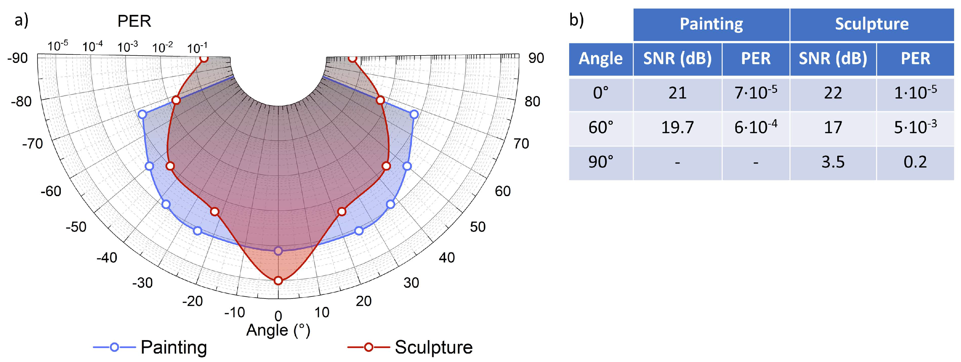
21], the authors implement a VLC-based surveillance system capable of detecting inadequate behaviours of visitors, which also provides information about artworks with very slow bit-rates despite the LoS configuration. The LoS configuration poses severe limits to realistic VLC applications, as it requires a direct alignment of the receiving devices with the VLC hotspot. A recent work demonstrated for the first time the possibility to implement VLC transmission to users in real museum environments using the light diffused by paintings in a real, non-Line-of-Sight (nLoS) configuration [22]. Such characterization is limited to two-dimensional (planar) artworks (mural and wood paintings, canvas), and reports no hints on the feasibility of VLC links when more complex artworks (such as sculptures) are involved. Hence, the large-scale deployment of VLC technology in museums asks for further investigation, so as to assess whether effective, nLoS-VLC links could also be established through artworks of a three-dimensional nature, such as sculptures and bas-reliefs.
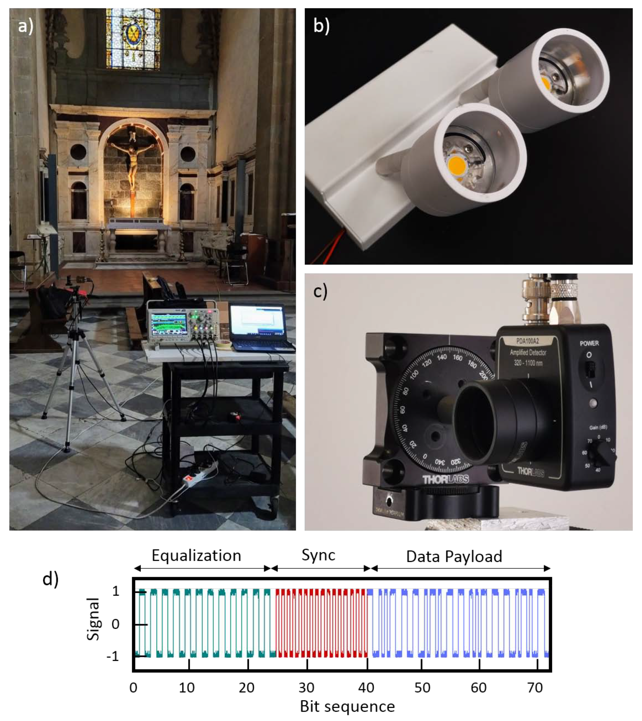
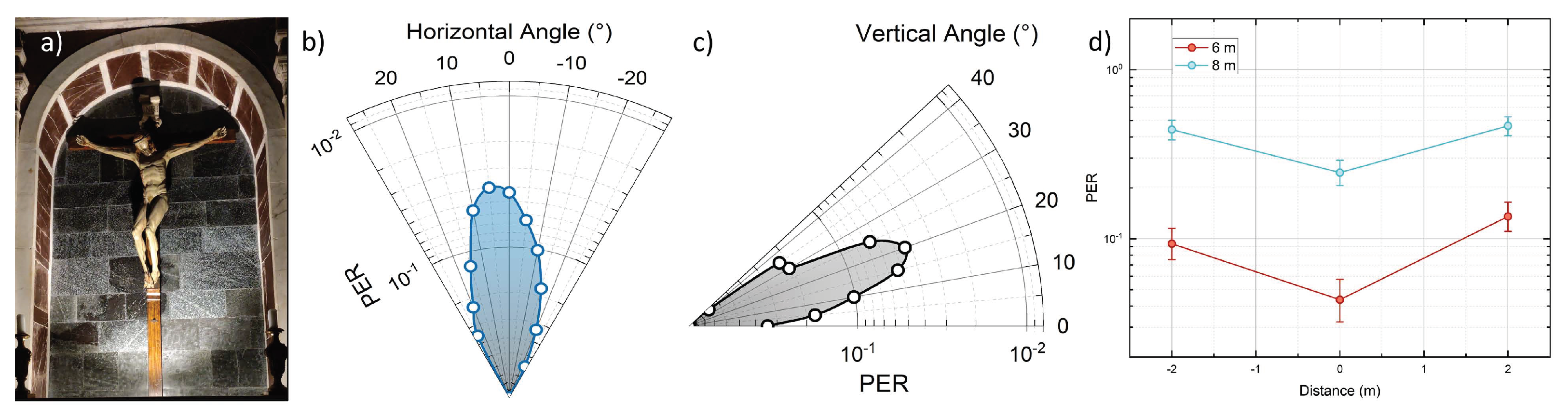
To this scope, in this paper we report for the first time the successful realization of VLC links in a real museum, exploiting diffusive illumination of wood and stone sculptures placed in their original locations (see Figure 1a) In particular, we have carried out an extensive characterization of our recently developed low-cost VLC system in terms of optical and telecom performances, exploiting nLoS diffusive illumination of two different sculpture masterpieces by Filippo Brunelleschi and Pagno Gherardo Bordoni inside the Basilica of Santa Maria Novella in Florence, Italy. We provide for an extensive characterization of the optical channel exploiting the actual LED lighting system of Basilica (Figure 1b), both in terms of intensity Signal-to-Noise Ratio (SNR) and Packet Error Rate (PER) patterns as a function of position, relative angle and distance from the three-dimensional artworks. Our system attains effective VLC transmission for distances up to 8 m for the Crucifix by Brunelleschi, and up to more than 4 m for the Holy Water Font by Bordoni. Noticeably, effective VLC links can be established for all the investigated view angles up to ±90° around the latter artwork (which features a high degree of cylindrical symmetry), and up to 8 m for the former sculpture, featuring very different make and location. We also provide an experimental determination of the sensitivity of our system to angular misalignment by determining the receiver’s FoV in terms of VLC transmission quality. Our work demonstrates the possibility to exploit VLC optical links using real LED lamps and diffusive illumination of real three-dimensional artworks, paving the way to full-fledged deployment of VLC technology in museum applications. We note that our results could also be relevant for several fields, beyond the pristine cultural heritage sector, as the possibility to exploit diffusive illumination of three-dimensional artifacts to cast data could be beneficial in indoor and outdoor public structures, e.g., buildings, offices, hospitals, industries.
The paper is organised as follows: in Section 2, we describe the experimental VLC setup; in Section 3, we detail the experimental campaign carried out in the Basilica; in Section 4, we report and discuss the experimental results; in Section 5, we give conclusions and perspectives for our work.

2. Experimental VLC Setup

With reference to Figure 2, our VLC transmitter (TX) is based on a low-cost digital microcontroller encoder, Arduino DUE, featuring an internal clock frequency of 84 MHz. The digital board, allowing for a minimum observed resolution of ∼1 μs in the generation of the Tx signals, supplies and modulates, by means of a customized current driver, a two-lamp high-power white LED source used for artworks lighting (Exenia Museo Mini 2L, with nominal power 9W × 2). The driver (see [23] for details) adds a 0–200% AC current modulation on top of the DC nominal 100% value of 0.7 A, required to provide the nominal light intensity on the artworks. This modulation scheme delivers the maximum possible modulation index, preserving the average brightness without appreciably affecting the LEDs lifetime [24,25].
The system transmits a continuous stream of 9-byte data packets at a baudrate of 28 kBaud. The packet includes a 3-byte pre-equalization frame, a 2-byte synchronization preamble and 4-byte data payload (see Figure 1d). The digital message is entirely generated by the Arduino board and sent to the high-power current modulator for injection into the LED source. The digital modulation is performed using Non-Return-to-Zero On-Off Keying (NRZ-OOK) scheme with Manchester encoding [3], which ensures a constant average illumination of the artworks.
The information carried by the light diffused from artworks is collected by an ad-hoc optical receiver (RX), consisting of a high-gain, AC-coupled photo-diode (Thorlabs PDA100A2, active area 75 mm 2 ) mounted on a precision two-axis rotation mount for precise angular alignment. The AC filtering stage is embedded in the hardware before the first transimpedance amplifier (TIA) stage (see [23] for further technical details), based on a high-speed op-amp with 130 MHz gain-bandwidth product. This effectively suppresses spurious DC stray light components at frequencies below 1 KHz such as sunlight, other artificial light sources, or the DC component of the illumination light source itself, so that the gain of the amplification stage can be increased to high values without incurring in DC saturation.
The photoreceiver amplified signal is digitised by a single-threshold Schmitt-trigger comparator stage and decoded by an Arduino DUE-based digital RX board. The firmware performs a bit-wise comparison on each received packet, discarding the pre-equalization bits, and comparing the preambles and data payload against a predefined message. PER is calculated by definition as the ratio of received packets featuring at least one wrong bit in the data payload to the total number of packets received showing correct preambles.
The FoV of the photoreceiver is physically limited at approximately 60° by a tube of diameter D = 25 mm and length L = 20 mm (Figure 1c), placed ahead of the active area of the photo-diode, aligned with the optical axis of RX. This configuration blocks possible light components impinging on the RX stage with large angles with respect to the optical axis, hence allowing to collect most of the light diffused by a specific artwork, but limiting at the same time the interference effects and crosstalks caused by signals cast by nearby VLC hotspots. As already observed [22], the proper choice of the RX FoV is a key element for future implementations of dedicated services and indoor positioning through diffusive VLC links.

3. Measurements Overview

In order to provide a complete characterization of VLC links and to analyse the possible implementation in real museum scenarios, it is important to also assess three-dimensional artworks. The experimental campaign has been carried out in the Basilica of Santa Maria Novella in Florence, Italy, which hosts a large set of heritage masterpieces. The artworks characterised here for VLC transmission are the wooden Crucifix by Filippo Brunelleschi (1415), preserved in the Gondi chapel, and the 
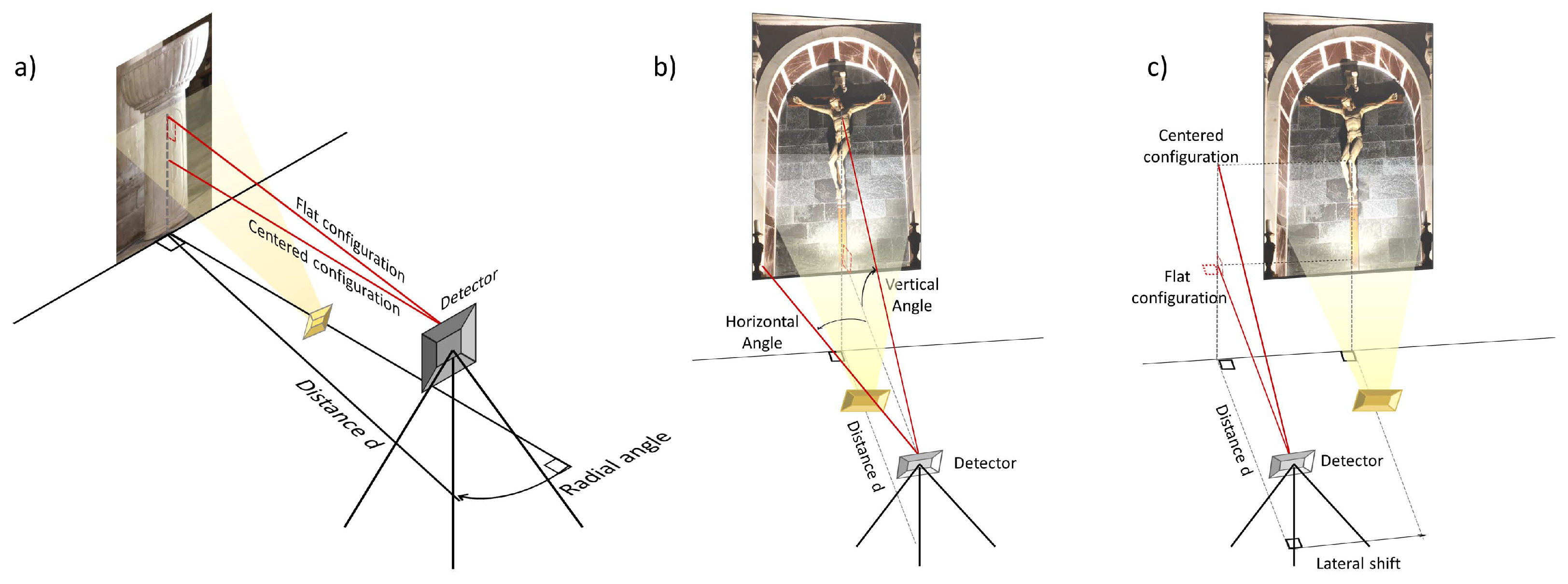
Holy Water Font by Pagno Gherardo Bordoni (XVII century). The sketch of the experimental setup is shown in Figure 3. These measurement configurations have been chosen in order to encompass a large set of possible scenarios that visitors may encounter in actual conditions, taking into account the relative position of each artwork with respect to visitors. With reference to Figure 3, the centered configuration is obtained by aiming the detector towards the geometric center of the artwork (corresponding to a vertical angle of about 20° ), whereas in the Flat configuration, the detector optical axis is parallel to the floor (0° vertical angle). The LED sources positioning is different for the two artworks. For the Holy Water Font, the LED light spot is placed on the floor at a distance of 1 m, whereas for the Crucifix, it is placed behind the altar (see Figure 1a), 1.5 m from the floor (same height as the crucifix baseline), and at 1.5 m from the crucifix. The light cones illuminate the artworks from below, in order to avoid undesirable flaring and disturbances to the visitors, as no direct light is cast or reflected towards the visitors’ eyes. In this configuration, indeed, most of the light is reflected upwards, so that only the diffused component reaches an observer placed in front of the artwork. Our RX stage is placed in front of each masterpiece at a height of 1.5 m from the floor, so as to mimic the position of a hypothetical observer. Given the configuration adopted, the detector mainly receives the diffused light component and the transmission is performed using a pristine nLoS, diffusive optical channel.
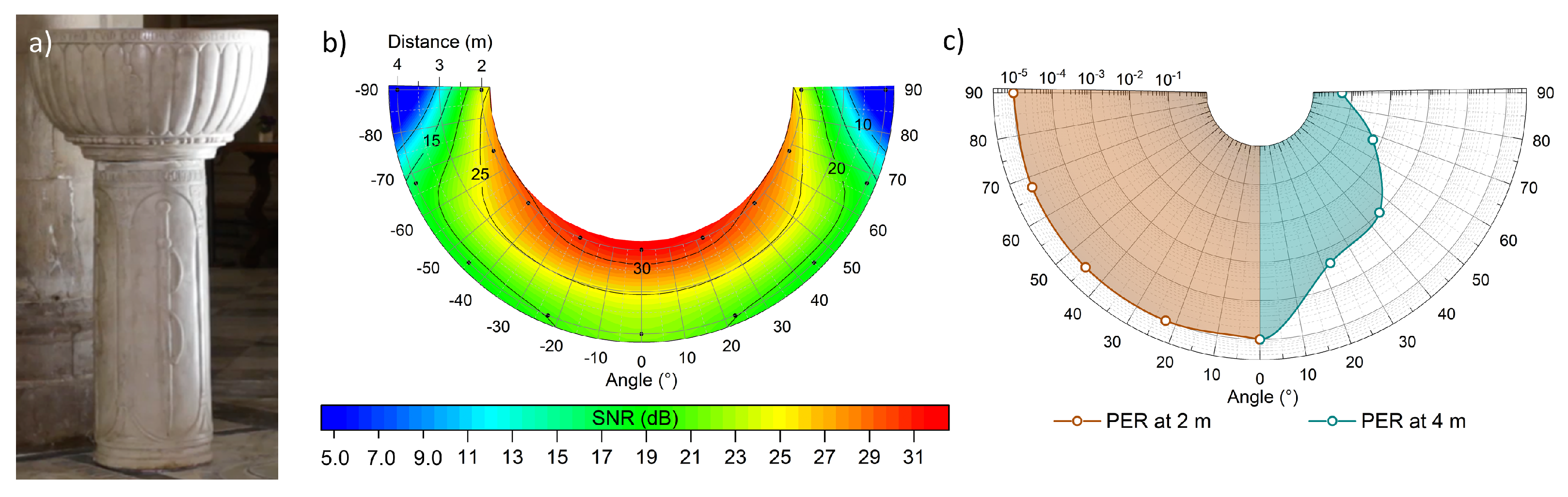
Measurements are performed on different experimental grids for the two artworks, in order to emulate realistic visitors position and view angles in the allowed observation area. The Holy Water Font (see Section 4.2) is a three-dimensional marble sculpture with a high degree of cylindrical symmetry, and has a large observation range due to its central location in the main aisle of the Basilica. This allows us to perform tests for angles up to 180° around the artwork itself, and the configuration that was considered to be the most insightful is the polar one (Figure 3a); we perform PER tests and intensity map measurements by recording the amplitude of the received VLC signal at RX as a function of the angle between receiver and artwork, for different values of distance.
Conversely, the Crucifix stands by the back wall of a chapel inaccessible to the visitor, who must keep a minimum distance of 6 m. The polar measurement is rendered inadequate by this constraint, so that we perform the experimental determination of the FoV of the receiver stage (Figure 3b) by scanning the vertical RX orientation angle with respect to the flat orientation. This measurement provides relevant information on the effect of angular misalignment between the RX optical axis and the artwork, which is a key element in view of the deployment of VLC handheld RX devices. On this artwork, we also characterise the effect on the quality of VLC transmission due to lateral displacements with respect to the ideal position of an observer placed in front of the artwork (Figure 3c).
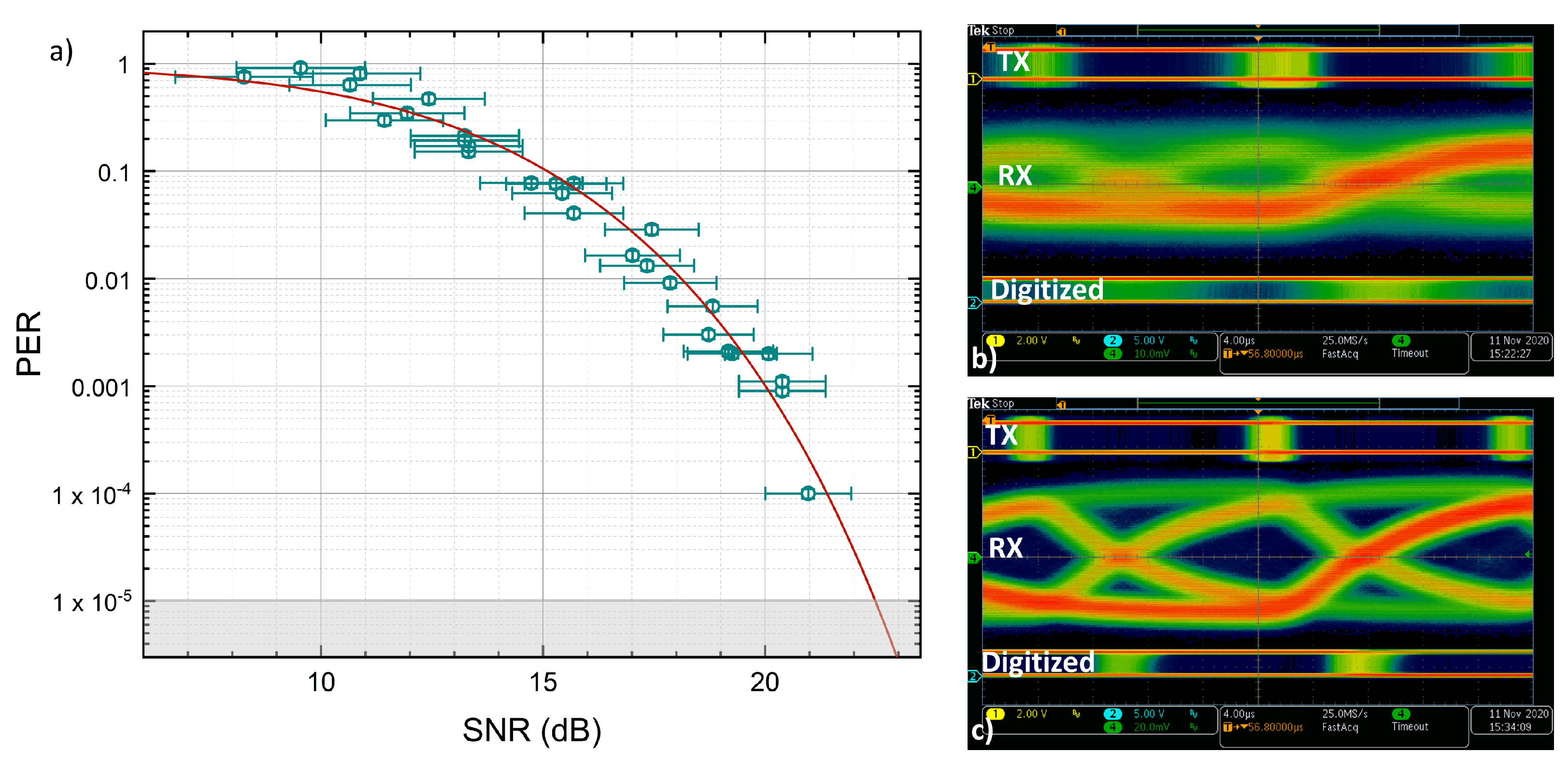
For the different configurations, we characterise the performance of our VLC system both in terms of SNR and PER value. We define the SNR as the ratio between the half-amplitude of the VLC signal, recorded after the photodetector with a 200-MHz, 2.5-GS/s digital oscilloscope (Tektronix MDO3024), and the corresponding Root Mean Square (RMS) noise value, which amounts to 2.2 mV. PER measurements are performed by sending up to 5 × 10 5 packets, so that the error-free communication threshold, corresponding to the minimum detectable PER, is 10 5 . The RX gain is set to 50, which is the maximum compatible with the electronic bandwidth required by the chosen baudrate of 28 kbaud, effectively acting as a 30 KHz analog low-pass filter on the received signal). We chose such baudrate as the best trade off between communication data rate and range of our VLC system, as higher baudrates would require lower RX gains, hence reducing the maximum reach of the VLC signal in front of the artworks [22]. Packets are spaced out by 3 ms (inter-packet delay, IPD), where no transmission is happening. In case of lower baudrates or longer inter-packet delays, IPD could also be filled with continuous modulation of the carrier in order to avoid potential flickering perception, which is, however, not appreciable with the tested baudrates. We note that the need for using a lower baudrate as compared to largest baudrates attainable by our system [26], is yielded by the nLoS configuration. This condition generally involves lower signal with respect to a direct LoS configuration, hence requiring larger gains of RX stage. This, in turn, limits the maximum attainable electronic bandwidth of the RX stage itself. It could be interesting, in future works, to address the opportunity to embed automatic gain control stages after TIA.
In order to provide a further, semi-quantitative evaluation of the combined effects of channel noise, intersymbol interference, and jitter in the VLC channel, we report, in addition to PER performances and intensity SNR maps, the eye diagrams obtained for two different SNR values, which are a general feature of our system and are valid for both the Crucifix and the stout.

4. Results and Discussion

4.1. PER Analysis and Quality of Communication Channel

PER is a common metric to assess the communication performances of communication systems, and in general its value relates to the SNR of the received signal [27]. For this reason, a convenient and reliable way to evaluate the communication performances of our system is to analyze the amplitude of the received signal on the whole experimental grid, for various relative positions and angles between TX and RX. Assuming a uniform distribution of the erroneous bits on the received packets, the PER can be directly related to the Bit Error Rate (BER) via PER = 1 ( 1 BER ) N , where N is the number of bits constituting packet [28]. Considering pure additive white Gaussian noise, we can assume BER to be related to the SNR of the received signal through the well-known Q-function: BER = Q ( SNR ) [27]. Combining the previous equations, PER can then be expressed as a function of received SNR as:
PER = 1 ( 1 Q ( SNR ) ) N = 1 1 1 2 erfc S / 2 T 2 σ RMS ,
where S is the amplitude of the signal received and σ RMS the standard deviation of the background noise. T is a parameter which takes into account the presence of a finite threshold in the detection of the VLC signal, intentionally introduced by our RX stage so as to mitigate the effect of channel noise, which would otherwise induce false triggering and lead to reduced transmission performances. In Figure 4a, we show measured PER as a function of received SNR. The green circles are the experimental data. Horizontal error bars correspond to uncertainty in detection of signal amplitude with the oscilloscope, whereas vertical error bars, negligible on this scale, are related to the observed variance of the PER in repeated experiments for a certain position of the receiver. As our data clearly show, our system is capable of attaining error-free communications in diffusive, nLoS configuration for SNR > 22 dB , whereas successful communication ( PER < 0.1 ) could be established for SNR exceeding 15 dB. Our data are also compared against predictions of a best fitting curve obtained through Equation (1) (red line in Figure 4). Our data are nicely fitted by predictions, thus confirming the hypothesis of additive white Gaussian noise affecting the VLC channel.
Figure 4 also shows the recorded eye patterns, in both low-signal ( SNR = 11 dB , PER 0.5 , panel (b)) and high-signal ( SNR = 22 dB , error-free, panel (c)) configurations.In both panels, we report traces corresponding to three different signals. The top trace (TX) corresponds to the TX signal generated by the Arduino DUE board, the central trace (RX) shows the analog output of the photoreceiver after TIA, and the bottom trace (digitized) shows the output of the comparator stage at receiver. The acquisition is self-triggered on the RX signal, so that the horizontal spread of transition edges in the digitised signal provides indication on the jitter in the reconstructed VLC digital signal, which depends on the signal quality and on the intrinsic ultimate time resolution of the Arduino DUE digital pins, which is of the order of 1 μs. Referring to the high-level signal eye diagram (Figure 4c), we observe a jitter of ∼2 μs on the TX trace and about twice this value in the digitised signal, which contains a larger amount of noise with respect to the TX. We remark that, in typical indoor environments, where flaring and seeing effects due to density fluctuations of the air can be neglected, TIA noise typically represents one of the largest noise components [29], as the small current generated in the photodiode makes TIA susceptible to thermal and shot noise, converting it to random jitter [30]. In the low-level signal configuration (Figure 4b) the RX trace features a much less defined eye pattern, and the signal amplitude approaches a value close to the comparator threshold T. This induces a larger jitter in the digitised signal (∼8 μs). However, a dedicated high-frequency digital filtering process introduced in our software improves the discrimination of transitions in the digitised signal, and successful VLC communications could be established even for SNR as low as 15 dB.

4.2. Bordoni’s Font: Polar Snr and Per Maps

The polar amplitude SNR and PER measurements for the Holy Water Font (Figure 5a) have been performed by scanning the horizontal angular position of the RX stage around the artwork, for two different radial distances (2 m and 4 m), and in an angular range of [−90°, +90°] with respect to the frontal position (Figure 3a). The photodetector is always oriented towards the artwork, and during the horizontal angular scan, the vertical angle is fixed in such a way that the RX stage always receives the maximum diffused light from the artwork. This configuration is referred to as Optimal in the following. Both horizontal and vertical angles are measured by the two orthogonal precision rotation stages equipping the RX stage (Section 2).
SNR and PER maps are reported in Figure 5b,c, respectively. Noticeably, at the regular observation distance of 2 m, error-free communication is obtained in the whole horizontal range [−90°, +90°], with SNR always exceeding 25 dB. As expected, both SNR and PER values are worse at 4 m, as a consequence of the decreased diffused intensity. Noticeably enough, PER 10 1 is still achieved at 4 m in the range [−90°, +90°] (minimum SNR = 3.5), and error-free communications are achieved at 0° radial angle (named frontal configuration hereinafter).
We note that the analyzed sculpture has a much smaller frontal extension with respect to the planar paintings reported in [22]. In the former case, therefore, one could intuitively expect a globally lower SNR value recorded at a given distance and for the same illumination level as compared to the latter, as the global amount of diffused light collected by RX is in general proportional to the size of the illuminated surface. Furthermore, the cylindrical diffusive surface tends to disfavor back diffusion of light at small angles, which is instead favoured by a plane configuration, due to the Lambertian shape of the diffusion lobe [31]. Following the pristine geometric considerations above, one could naively expect reduced SNR values even in the frontal configuration with respect to the two-dimensional paintings case. However, our data show a non-trivial behaviour of the SNR maps for the three dimensional sculpture. To get more insight in the differences yielded by two- and three-dimensional artworks in VLC performances, we report in Figure 6 a direct comparison between our PER characterization for the sculpture, along with a similar characterization for the case of the plane mural painting Holy Trinity by Masaccio [22], both performed at 4 m distance. Panel a) reports the PER data (circles), along with a spline interpolation for both painting and sculpture case, whereas panel (b) highlights specific PER values corresponding to relevant angular positions in tabular form. Differently from expectations, the Holy Water Font sculpture features a better SNR (22 dB) in the frontal configuration as compared to the mural painting case, achieving error-free communication. Furthermore, better PER performances are maintained in a ± 15° angular range (see panel a), whilst PER performances get worse at large angles with respect to the painting case, still allowing successful packet delivery in the whole 180° angular range.
The peculiar shape of the recorded PER pattern shown in Figure 6 can be ascribed to the geometric differences between artworks discussed above, and to the nature of the finished surface of the sculpture, whose white marble finish strongly limits absorption effects of visible light as compared to the coloured painting. Moreover, the reduced distance between the spotlight and the sculpture leads to a larger light irradiance as compared to the paintings case. The combination of such features makes the performances of our VLC prototype with sculptures better than initially expected for the frontal configuration, yet allowing for successful communication at very large view angles. A detailed prediction of the emission lobes in case of realistic, three-dimensional diffusive surfaces requires further studies in terms of optical models, nevertheless our results highlight the possibility to establish effective VLC communication using diffusive illumination of three-dimensional artworks in museum settings.
As our channel is a non-LoS, diffusive one, we argue that IEEE 802.15.7 PHY V type for diffused light sources [32] could be the most adequate to encompass applications like those described in our work. As mode 6 of PHY V also embeds OOK Manchester as modulation/encoding, our results show that, despite the relatively low baudrate of 28 kBaud, our system is highly outperforming the bandwidth of 2.2 kHz requested by PHY V mode 6. By properly setting (in future developments) the software to include, e.g., Hamming error correction codes, we expect to attain bitrates much higher than the 400 bps which are requested by IEEE 802.15.7 PHY V.

4.3. Brunelleschi’S Crucifix: FoV and Side Shift

As described in Section 3, the wooden Crucifix sculpture by Brunelleschi (Figure 1a and Figure 7a) is located in a niche by the back wall of a chapel, so that visitors can only move in a very narrow angular range in front of the artwork and must keep a minimum distance of 6 m. For this reason, we did not perform polar tests for this artwork. However, we exploited the Crucifix to perform FoV and side displacement sensitivity tests on the quality of VLC transmission. Indeed, such tests provide precious insights about the capability to discern data fluxes coming from the neighbouring VLC hotspots (artworks) and, therefore, on the potential use of VLC for dedicated services and localization.
Figure 7b shows experimental PER values in centered configuration as a function of horizontal angular misalignment of the RX optical axis with respect to the artwork. Acceptable packet reception (PER > 0.1) occurs in an angular range [−10°, +15°], yielding an effective FoV of 25°for telecom performances of our VLC system. The small angular asymmetry (∼5° ) is most probably due to the asymmetry of the artwork and of the illumination pattern of the LED sources. We also remark that a contribution to the VLC signal is provided by the stone wall composing the background of the sculpture. This suggests that positioning three-dimensional sculptures near walls could improve the performance of VLC communication. We note that this behaviour is a peculiar feature of VLC as, differently from other RF-based communication protocols, multipath interference is not necessarily detrimental for PER performances, since the induced phase shift in the OOK-NRZ VLC signal is negligible for bit rates up to hundreds of Mbps [23]. In order to get relevant insights on the possibility to exploit VLC in real museums to provide for localization and dedicated services, we note that the projection of the measured FoV angle on the background wall at 6 m covers a horizontal range of [−1.06, +1.6] m. This range provides an useful indication on the minimum separation (∼2.6 m) required between artworks to avoid interference with datastreams cast by nearby VLC hotspots. Indeed, VLC-enabled artworks placed outside this range would not induce appreciable interference effects in the datastream received at RX. Figure 7c shows a similar characterisation as a function of vertical RX orientation angle (see Figure 3c). 0° corresponds to the flat orientation of RX. Good packet reception (PER > 0.1) occurs in the vertical angular range [+10°, +30°]. The same analysis as above yields a minimum required vertical spacing of artworks of ∼2 m.
As anticipated in Section 3, another important aspect addressed by our experimental campaign is the effect of lateral shift in the RX (observer) position on the telecom performances of the VLC system. We report such measurement in Figure 7d, where PER values are shown as a function of the lateral displacement of RX with respect to the frontal position (see also Figure 3c), for various distances. Open circles show the measured PER at 6 m (red) and 8 m (cyan) distance, in centered configuration with 0° horizontal RX angle. Interestingly, despite the larger attained distance and differently from what has been observed in the case of other artworks (i.e., the mural painting by Masaccio (Figure 6 of [22]), we record a rather weak effect of lateral displacement on PER. This feature can be ascribed to the peculiar position of the sculpture, placed inside a narrow, 5 m long chapel delimited by diffusive/reflective stone and marble walls (see also Figure 1a). In such layout, similarly to what has been observed earlier in a different (vehicular) VLC setup [24], reflection and diffusion from nearby surfaces help redirect the diffused modulated light, hence increasing the VLC SNR values in the measurements grid. This observation suggests that effects of reflections from additional surfaces surrounding VLC hotspots could also play a non-negligible role in position tracking protocols and dedicated services based on VLC diffusive-channel VLC, and definitely deserve further studies in relevant scenarios.

5. Conclusions

In this work we report, for the first time, successful VLC data transfer exploiting standard LED illumination of real three-dimensional sculptures in a museum. We present a detailed characterisation of our novel low-cost VLC prototype which uses a diffusive, nLoS channel through the standard LED-based lighting system in the famous Basilica of Santa Maria Novella in Florence, Italy. In particular, our experimental campaign explores the performances of the prototype on two different sculpture masterpieces (the wooden Crucifix by Filippo Brunelleschi and the marble Holy Water Font by Bordoni), in their original location. These artworks have been chosen for their different positioning, material and shape, so as to encompass a comprehensive set of conditions found in actual museums. We perform extensive tests, recording PER and SNR maps as a function of the position of the RX stage, mimicking realistic viewpoints of the observers. Our results show that the system achieves successful VLC data transfer at baudrates up to 28 kBaud for distances of up to 8 m, and in a with angles between the LED source axis and the observer LoS up to 90°. For what concerns the font, which features a white marble surface and a high degree of cylindrical symmetry, we highlight the possibility to establish error-free communications ( PER < 10 5 ) in the whole 180° angular range, at a realistic distance of 2 m. We show how the three-dimensional nature of the artifact affects the VLC channel, finding a non-trivial shape of the PER lobe as a function of the angular position of the observer which is quite different when compared to plane artworks (paintings, canvas, etc.). In the case of the wooden Crucifix by Brunelleschi, located inside a dedicated stone chapel where the minimum allowed observation distance is 6 m, we show the feasibility of successful VLC communication up to 8 m, with best observed PER 4 × 10 2 at 6 m, which could be improved further by introducing proper software Error Correction Coding (ECC) in our prototype. For this artwork, we also provide for a detailed characterization of effective communication FoV of our system. We observe vertical (horizontal) FoV values of 20° (25° ) for the reference value PER = 0.1 , suggesting a minimum separation of ∼2 m between artworks, in similar illumination and distance conditions, so as to allow effective discrimination of VLC signals received from nearby artworks. This is an essential parameter to assess the capability of VLC diffusive communication systems to provide indoor positioning and position-based services to users. We also quantify the effects of lateral displacements in the observer position on the quality of VLC transmission, showing the effect of side walls in enhancing the SNR level of VLC signal due to phase-insensitive multipath reflection mechanisms. Our results demonstrate, for the first time, the possibility to implement VLC wireless links through three-dimensional artworks in museums by exploiting standard LED illumination infrastructures. This achievement is an essential step towards the full-fledged deployment of VLC technology in the cultural heritage sector, where sculptures and bas-reliefs are widespread, and completes the characterization of VLC links recently performed on two-dimensional artworks (paintings, canvas) [22]. Our results could also have sizeable impact in diverse indoor and outdoor application scenarios where VLC nLoS channels could play a fundamental role by exploiting diffusion from non-planar objects to cast wireless data to users (e.g., shops, hospitals, offices, industries).

Author Contributions

Conceptualization, M.M., M.S., F.T., C.R. and J.C.; methodology, M.M., M.S. and J.C.; software, J.C.; validation, C.R. and J.C.; formal analysis, M.M., M.S., F.T., C.R. and J.C.; investigation, M.M., M.S. and J.C.; resources, C.R. and J.C.; data curation, M.S. and M.M.; original draft preparation, M.M. and J.C.; supervision, J.C.; funding acquisition, C.R. and J.C. All authors have read and agreed to the published version of the manuscript.

Funding

This work has been carried out under partial financial support of project MIUR PON 2017 ARS01_00917 “OK-INSAID”, MIUR FOE Progetto Premiale 2015 “OpenLab 2”, MIUR PON 2014-2020 "DARIAH-IT", and H2020-INFRAIA-2019-1 “IPERION HS” (GA 871034).

Institutional Review Board Statement

Not applicable.

Data Availability Statement

Data available on request due to restrictions. The data presented in this study are available on request from the corresponding author. The data are not publicly available due to privacy.

Acknowledgments

This work is performed by CNR-INO VLC Lab and CNR-ISPC in collaboration with European Laboratory for NonLinear Spectroscopy (LENS). All of the artworks shown or represented in our work are property of Fondo Edifici di Culto, Ministero dell’Interno. The authors wish to thank Opera per Santa Maria Novella in Firenze and in particular Archt. F. Sgambelluri for valuable and constant support during the organization and execution of the whole campaign. Authors would also like to thank the company Fagioli&Cappelli srl for providing the LED lamps used in the experiments, and all members of the VisiCoRe joint laboratory for insightful discussions.

Conflicts of Interest

The authors declare no conflict of interest.

References

  1. O’Brien, D.C.; Zeng, L.; Le-Minh, H.; Faulkner, G.; Walewski, J.W.; Randel, S. Visible light communications: Challenges and possibilities. In Proceedings of the 2008 IEEE 19th International Symposium on Personal, Indoor and Mobile Radio Communications, Cannes, France, 15–18 September 2008; pp. 1–5. [Google Scholar] [CrossRef]
  2. Chow, C.W.; Yeh, C.H.; Liu, Y. Optical Wireless Communications (OWC)—Technologies and Applications. In Proceedings of the 2020 Opto-Electronics and Communications Conference (OECC), Taipei, Taiwan, 4–8 October 2020; pp. 1–3. [Google Scholar] [CrossRef]
  3. Rajagopal, S.; Roberts, R.D.; Lim, S. IEEE 802.15.7 visible light communication: Modulation schemes and dimming support. IEEE Commun. Mag. 2012, 50, 72–82. [Google Scholar] [CrossRef]
  4. Khan, L.U. Visible light communication: Applications, architecture, standardization and research challenges. Digit. Commun. Netw. 2017, 3, 78–88. [Google Scholar] [CrossRef] [Green Version]
  5. Haas, H.; Yin, L.; Wang, Y.; Chen, C. What is LiFi? J. Light. Technol. 2016, 34, 1533–1544. [Google Scholar] [CrossRef]
  6. Tsonev, D.; Chun, H.; Rajbhandari, S.; McKendry, J.J.D.; Videv, S.; Gu, E.; Haji, M.; Watson, S.; Kelly, A.E.; Faulkner, G.; et al. A 3-Gb/s Single-LED OFDM-Based Wireless VLC Link Using a Gallium Nitride μLED. IEEE Photonics Technol. Lett. 2014, 26, 637–640. [Google Scholar] [CrossRef]
  7. Steigerwald, D.A.; Bhat, J.C.; Collins, D.; Fletcher, R.M.; Holcomb, M.O.; Ludowise, M.J.; Martin, P.S.; Rudaz, S.L. Illumination with solid state lighting technology. IEEE J. Sel. Top. Quantum Electron. 2002, 8, 310–320. [Google Scholar] [CrossRef]
  8. Vitasek, J.; Jargus, J.; Hejduk, S.; Stratil, T.; Latal, J.; Vasinek, V. Phosphor decay measurement and its influence on communication properties. In Proceedings of the 2017 19th International Conference on Transparent Optical Networks (ICTON), Girona, Catalonia, Spain, 2–6 July 2017; pp. 1–4. [Google Scholar] [CrossRef]
  9. Grubor, J.; Lee, S.C.J.; Langer, K.; Koonen, T.; Walewski, J.W. Wireless High-Speed Data Transmission with Phosphorescent White-Light LEDs. In Proceedings of the 33rd European Conference and Exhibition of Optical Communication—Post-Deadline Papers (published 2008), Berlin, Germany, 16–20 September 2007; pp. 1–2. [Google Scholar]
  10. Huang, X.; Wang, Z.; Shi, J.; Wang, Y.; Chi, N. 1.6 Gbit/s phosphorescent white LED based VLC transmission using a cascaded pre-equalization circuit and a differential outputs PIN receiver. Opt. Express 2015, 23, 22034–22042. [Google Scholar] [CrossRef] [PubMed]
  11. Khalid, A.M.; Cossu, G.; Corsini, R.; Choudhury, P.; Ciaramella, E. 1-Gb/s Transmission Over a Phosphorescent White LED by Using Rate-Adaptive Discrete Multitone Modulation. IEEE Photonics J. 2012, 4, 1465–1473. [Google Scholar] [CrossRef] [Green Version]
  12. Zhang, H.; Yang, A.; Feng, L.; Guo, P. Gb/s Real-Time Visible Light Communication System Based on White LEDs Using T-Bridge Cascaded Pre-Equalization Circuit. IEEE Photonics J. 2018, 10, 1–7. [Google Scholar] [CrossRef]
  13. Al-Sarawi, S.; Anbar, M.; Alieyan, K.; Alzubaidi, M. Internet of Things (IoT) communication protocols: Review. In Proceedings of the 2017 8th International Conference on Information Technology (ICIT), Amman, Jordan, 17–18 May 2017; pp. 685–690. [Google Scholar] [CrossRef]
  14. Samuel, S.S.I. A review of connectivity challenges in IoT-smart home. In Proceedings of the 2016 3rd MEC International Conference on Big Data and Smart City (ICBDSC), Muscat, Oman, 15–16 March 2016; pp. 1–4. [Google Scholar] [CrossRef]
  15. Luo, J.; Fan, L.; Li, H. Indoor Positioning Systems Based on Visible Light Communication: State of the Art. IEEE Commun. Surv. Tutor. 2017, 19, 2871–2893. [Google Scholar] [CrossRef]
  16. Pergoloni, S.; Mohamadi, Z.; Vegni, A.M.; Ghassemlooy, Z.; Biagi, M. Visible Light indoor positioning through colored LEDs. In Proceedings of the 2017 IEEE International Conference on Communications Workshops (ICC Workshops), Paris, France, 21–25 May 2017; pp. 150–155. [Google Scholar] [CrossRef]
  17. Cosmas, J.; Meunier, B.; Ali, K.; Jawad, N.; Meng, H.; Goutagneux, F.; Legale, E.; Satta, M.; Jay, P.; Zhang, X.; et al. 5G Internet of radio light services for Musée de la Carte à Jouer. In Proceedings of the 2018 Global LIFI Congress (GLC), Paris, France, 8–9 February 2018; pp. 1–6. [Google Scholar] [CrossRef]
  18. Gökrem, L.; Durgun, M.; Durgun, Y. Indoor Location Control with Visible Light Communication. In Proceedings of the 2019 3rd International Conference on Advanced Information and Communications Technologies (AICT), Lviv, Ukraine, 2–6 July 2019; pp. 314–316. [Google Scholar] [CrossRef]
  19. Shi, L.; Shi, D.; Zhang, X.; Meunier, B.; Zhang, H.; Wang, Z.; Vladimirescu, A.; Li, W.; Zhang, Y.; Cosmas, J.; et al. 5G Internet of Radio Light Positioning System for Indoor Broadcasting Service. IEEE Trans. Broadcast. 2020, 66, 534–544. [Google Scholar] [CrossRef]
  20. Udtewar, S.; Dsouza, D.; Aghamkar, A. Visible Light Information System for Museums. Int. J. Sci. Res. Publ. 2019, 9, 2250–3153. [Google Scholar] [CrossRef]
  21. Kim, M.; Suh, T. A Low-Cost Surveillance and Information System for Museum Using Visible Light Communication. IEEE Sens. J. 2019, 19, 1533–1541. [Google Scholar] [CrossRef]
  22. Seminara, M.; Meucci, M.; Tarani, F.; Riminesi, C.; Catani, J. Characterization of a VLC system in real museum scenario using diffusive LED lighting of artworks. Photon. Res. 2021, 9, 548–557. [Google Scholar] [CrossRef]
  23. Caputo, S.; Mucchi, L.; Cataliotti, F.; Seminara, M.; Nawaz, T.; Catani, J. Measurement-based VLC channel characterization for I2V communications in a real urban scenario. Vehicular Communications 2021, 28, 100305. [Google Scholar] [CrossRef]
  24. Seminara, M.; Nawaz, T.; Caputo, S.; Mucchi, L.; Catani, J. Characterization of Field of View in Visible Light Communication Systems for Intelligent Transportation Systems. IEEE Photonics J. 2020, 12, 1–16. [Google Scholar] [CrossRef]
  25. Nawaz, T.; Seminara, M.; Caputo, S.; Mucchi, L.; Catani, J. Low-Latency VLC System with Fresnel Receiver for I2V ITS Applications. J. Sens. Actuator Netw. 2020, 9, 35. [Google Scholar] [CrossRef]
  26. Nawaz, T.; Seminara, M.; Caputo, S.; Mucchi, L.; Cataliotti, F.S.; Catani, J. IEEE 802.15.7-Compliant Ultra-Low Latency Relaying VLC System for Safety-Critical ITS. IEEE Trans. Veh. Technol. 2019, 68, 12040–12051. [Google Scholar] [CrossRef] [Green Version]
  27. Stern, H.; Mahmoud, S.; Stern, L. Communication Systems: Analysis and Design; Pearson Prentice Hall: Upper Saddle River, NJ, USA, 2004. [Google Scholar]
  28. Khalili, R.; Salamatian, K. A new analytic approach to evaluation of packet error rate in wireless networks. In Proceedings of the 3rd Annual Communication Networks and Services Research Conference (CNSR’05), Halifax, NS, Canada, 16–18 May 2005; pp. 333–338. [Google Scholar] [CrossRef]
  29. Hancock, J. Jitter—Understanding it, Measuring It, Eliminating It Part 1: Jitter Fundamentals. High Freq. Electron. Summit Tech. Media 2004, 4, 44–50. [Google Scholar]
  30. Breed, G. Analyzing Signals Using the Eye Diagram. High Freq. Electron. Summit Tech. Media 2005, 4, 50–53. [Google Scholar]
  31. Akanegawa, M.; Tanaka, Y.; Nakagawa, M. Basic study on traffic information system using LED traffic lights. IEEE Trans. Intell. Transp. Syst. 2001, 2, 197–203. [Google Scholar] [CrossRef]
  32. IEEE Standard for Local and metropolitan area networks–Part 15.7: Short-Range Optical Wireless Communications. IEEE Std 802.15.7-2018 (Revision of IEEE Std 802.15.7-2011) 2019, 1–407. [CrossRef]
Figure 1. (a) Overview of VLC experimental setup used in the Basilica of Santa Maria Novella; (b) LED light sources used as TX stage and (c) custom RX stage, with shield tube for FoV adjustment visible. D represents the input tube diameter, L its length. (d) Data frame composition (NRZ-OOK with Manchester encoding) used in the experiments (see text).
Jsan 10 00045 g001
Figure 2. Hardware blocks in our VLC system. Left part (TX): The transmitter block includes the same light source used in the museum, supplied with a current modulator controlled by a digital encoder. Right part (RX): the block includes a modified commercial photodetector, with tailored FoV, and a digital decoder based on Arduino DUE.
Jsan 10 00045 g002
Figure 3. Layout for SNR and PER measurements (see text): (a) polar, (b) FoV, (c) lateral displacement.
Jsan 10 00045 g003
Figure 4. (a) Example of measured PER as a function of SNR on the received amplitude. Green circles correspond to experimental data, with horizontal error bars showing the uncertainty in the amplitude measurement. The vertical error bars are due to the variance on the number of wrong packets on consecutive measurements and are smaller than the symbol size. The red line is the best fit curve by the model given in the text. The shaded area represents the error-free region (higher limit) given by the maximum number of packets used in the tests. (b,c) Heat maps showing eye-diagrams for PER > 0.1 with SNR = 11 dB (b), and error-free communication achieved with SNR = 22 dB (c). Three traces are shown: TX, RX, and the (digitized) signal after comparator. The horizontal scale is 4 μs. The acquisition is self-triggered on the RX signal, so that the horizontal spread of the digitized signal corresponds to a jitter of 1–4 μs in the reconstructed VLC digital signal, depending on the SNR level.
Jsan 10 00045 g004
Figure 5. (a) Bordoni’s Holy Water Font; (b) polar map of the received SNR amplitude value considering a noise of σ RMS = 2.2 mV . A 10 dB SNR is still guaranteed at 4 m and with 75° misalignment. Black dots represent the experimental data, whereas the colour map is a cubic spline interpolation. (c) Communication performances in terms of PER at 2 m (orange area) and 4 m (green area) as a function of the radial angle. At 2 m, an error-free communication has been performed for all the angles, while at 4 m a PER < 10 1 is always guaranteed.
Jsan 10 00045 g005
Figure 6. (a) Comparison between PER values at 4 m for the wall painting (Holy Trinity by Masaccio, blue circles) and for marble sculpture (Holy Water Font by Bordoni, red circles). Solid lines are spline interpolation to data. (b) Tabular comparison for relevant angles of 0°, 60°, and 90°.
Jsan 10 00045 g006
Figure 7. Experimental determination of effective RX FoV in terms of PER performances. Data report measured PER values relative to Brunelleschi’s Crucifix (panel (a)) as a function of the horizontal (b) an vertical (c) angular orientation of RX axis, at 6 m distance. Panel (d) reports the measured PER for side shifts of ±2 m, at 6 m (red) and 8 m (cyan) distance from artwork.
Jsan 10 00045 g007
Publisher’s Note: MDPI stays neutral with regard to jurisdictional claims in published maps and institutional affiliations.

