Toward Campus Mail Delivery Using BDI †


1
School of Electrical Engineering and Computer Science, University of Ottawa, Ottawa, ON K1N 6N5, Canada
2
Department of Systems and Computer Engineering, Carleton University, Ottawa, ON K1S 5B6, Canada
*
Authors to whom correspondence should be addressed.
†
This paper is an extended version of our paper published in In Cardoso, R.C.; Ferrando, A.; Briola, D.; Menghi, C.; Ahlbrecht, T. In Proceedings of the First Workshop on Agents and Robots for reliable Engineered Autonomy (AREA 2020), Virtual Event, 4 September 2020; pp. 127–143.
J. Sens. Actuator Netw. 2020, 9(4), 56; https://doi.org/10.3390/jsan9040056
Submission received: 30 October 2020
/
Revised: 23 November 2020
/
Accepted: 29 November 2020
/
Published: 8 December 2020
(This article belongs to the Special Issue Agents and Robots for Reliable Engineered Autonomy)
Abstract
:Autonomous systems developed with the Belief-Desire-Intention (BDI) architecture tend to be mostly implemented in simulated environments. In this project we sought to build a BDI agent for use in the real world for campus mail delivery in the tunnel system at Carleton University. Ideally, the robot should receive a delivery order via a mobile application, pick up the mail at a station, navigate the tunnels to the destination station, and notify the recipient. In this paper, we discuss how we linked the Robot Operating System (ROS) with a BDI reasoning system to achieve a subset of the required use casesand demonstrated the system performance in an analogue environment. ROS handles the connections to the low-level sensors and actuators, while the BDI reasoning system handles the high-level reasoning and decision making. Sensory data is sent to the reasoning system as perceptions using ROS. These perceptions are then deliberated upon, and an action string is sent back to ROS for interpretation and driving of the necessary actuator for the action to be performed. In this paper we present our current implementation, which closes the loop on the hardware-software integration and implements a subset of the use cases required for the full system. We demonstrated the performance of the system in an analogue environment.
1. Introduction
An autonomous agent can be defined as a system that pursues its own agenda, affecting what it senses in the future, by sensing the environment and acting on it over time [1]. Autonomous systems should be designed in such a manner that they can intelligently react to ever-changing environments and operational conditions. Given such flexibility, they can accept goals and set a path to achieve these goals in a self-responsible manner while displaying some form of intelligence.
The Belief-Desire-Intention (BDI) framework is meant for developing autonomous agents, in that it defines how to select, execute and monitor the execution of user-defined plans (Intentions) in the context of current perceptions and internal knowledge of the agent (Beliefs) in order to satisfy the long-term goals of the agent (Desires). However, so far, very few applications of BDI have been observed outside of simulated or virtual environments. In this paper, we describe how we built our autonomous robot that uses BDI (and specifically, the Jason implementation of the BDI AgentSpeak language) and Robot Operating System (ROS) to eventually deliver interoffice mail in the Carleton University campus tunnels. The Carleton tunnel system allows people to go from one campus building to another without having to face Ottawa’s harsh winters and makes for a more controlled environment for our robot to navigate. However, being underground also means that access to Global Navigation Satellite System (GNSS) signals, such as Global Positioning System (GPS), is not possible, and internet access is limited to certain areas. In this context, ultimately the robot will have to know where it is and where to deliver mail, but there are also some sub-goals, like obstacle avoidance and battery recharge, which it might have to achieve in order to get to its main goal.
Our use of BDI for this work is two fold. First, BDI provides a good goal-oriented agent architecture that is resilient to plan failure and changes to context. It also supports the notion of shorter-term and longer-term plans that can be organized so as not to conflict with each other. Granted, BDI may not necessarily be the perfect ad hoc solution for agent-based robotics, but there is just not enough literature to demonstrate the appropriateness of BDI (or lack thereof) in robotics.
There are alternative agent architectures to BDI that are available, for example the subsumption architecture [2,3]. Although it is possible that the robotic behaviours implemented in this paper could have implemented the same robot using subsumption, our longer-term goals for this project would likely make the use of other architectures more difficult. BDI is goal-directed whereas in the case of the subsumption architecture, the agent behaviour emerges from the various layers built into the agent [4].
In the remainder of the paper, we first provide some background on BDI and ROS (Section 2), and related work on known implementations of agent-based robots (Section 3). We then describe our overall hardware and software architecture (Section 4). Next, we describe in more detail the hardware and software implementation (Section 5) followed by an evaluation of the architecture (Section 6) and a discussion of the lessons learned using our method for agent-based robotics (Section 7). Our conclusion (Section 8) provides a summary of the key accomplishments presented in this paper as well as our plans for future work. Additional details with respect to the hardware implementation, specifically related to our connections between our computer and the robot’s power system and our line sensor circuit, used for path following, are provided (Appendix A).
2. Background
We provide background on BDI and the AgentSpeak language in Section 2.1. We then introduce ROS in Section 2.2.
2.1. Belief-Desire-Intention Architecture
The principles that underpin BDI originated in the 1980s cognitive science theory as a means of modelling agency in humans [5]. Since that time, this model has been applied in the development of software agents as well as the field of Multi Agent System (MAS). An example of a popular implementation of applying BDI to agent reasoning is Jason [1,6]. In Jason, an agent’s initial belief base, goals and plans are specified using AgentSpeak.
In BDI systems, a software agent performs reasoning based upon internally held beliefs, stored in a belief base, about itself and the task environment. The agent also has objectives, or desires, that are provided to it, as well as a plan base, which contains various means for achieving goals depending on the agent’s context. The agent’s reasoning cycle consists of first perceiving the task environment and receiving any messages. From this information, the agent can then decide on a course of action suitable to the context provided by those perceptions, the agent’s own beliefs, messages received, and desires. Once this course of action has been selected, we can say that the agent has set an intention for itself. These plans can include updating the belief base, sending messages to other agents, and taking some action. As the agent continues to repeat its reasoning cycle, it can reassess the applicability of its intentions as it perceives the environment, dropping intentions that are no longer applicable [1,6].
Agents developed for BDI systems using Jason are programmed using a language called AgentSpeak. This is a logic-based programming language that bears similarities to Prolog. The syntax provides a means for specifying initial beliefs for the agent to have, rules that can be applied for reasoning as well as plans that can be executed. The Extended Backus–Naur form (EBNF) description of AgentSpeak can be found in Appendix A.1 of [1]. Here, we provide a brief overview of AgentSpeak.
In general, AgentSpeak plans have the form of:
triggeringEvent : context <- body.
A triggering event is the addition or deletion of a belief, achievement goal, or a test goal. The syntax of these triggers takes the form of predicates. To differentiate goals from beliefs, achievement goals begin with an exclamation mark (!) and test goals begin with a question mark (?). Triggers that are based on the addition or deletion of a belief or goal begin with a positive (+) or negative (−) sign respectively. An achievement goal is used for providing the agent with an objective with respect to the state of the environment whereas a test goal is generally used for querying the state of the environment. The context is a set of conditions that must be satisfied for the plan to be applicable based on the state of the agent’s belief base. This is a logical sentence that can use both beliefs as well as previously defined rules. The body includes the instructions for the agent to follow for executing the plan. The plan body can include the addition or deletion of beliefs and/or goals as well as actions for the agent to perform [1].
Listing 1 provides an example of an AgentSpeak plan. Here, we have a simple plan for the achievement goal of !goTo(LOCATION). The variable LOCATION, interpreted as a variable due to the capitalization of the first letter, specifies the agent’s destination. This specific plan is meant for the context where the agent has arrived at the destination. Therefore, the plan context requires the agent have direction(LOCATION,arrived) be a logical consequence of its belief base. This can either be the result of this predicate being perceived, the belief being communicated to the agent, or adopted through plan execution. This context is applicable when LOCATION unifies the goal with the agent’s belief. For example, during execution, the agent could adopt the goal of !goTo(post1). In this case, post1 specifies the specific location that the agent needs to travel to. This plan would become applicable if the predicate direction(post1,arrived) is a logical consequence of the belief base. The body of the plan is for the agent to execute the stop action, specified using the drive(stop) predicate.
Listing 1. Example AgentSpeak program.
+!goTo(LOCATION)
: direction(LOCATION,arrived)
<- drive(stop).
BDI enables agent-based systems to perform reasoning based upon beliefs in order to enable the agent to achieve its goals, making it an attractive way for the implementation of autonomous systems. However, for the application in this paper, this language needs a means to communicate to its sensors and actuators. ROS, described in the next section, provides the middleware necessary to connect Jason to hardware.
2.2. Robot Operating System (ROS)
ROS is a package for developing software for robotic applications [7]. ROS has an active community supporting a variety of robotic platforms, sensors, and actuators. By building robotic applications that are compatible with ROS, developers enable their applications to be compatible with other devices and software nodes supported by the community. This allows developers to focus on the implementation of individual nodes and enables flexibility to use one of many available nodes that are compatible with ROS. For example, various hardware component developers have made ROS nodes available, allowing systems developers to use those modules without concern as to how those nodes are implemented in detail.
ROS operates using a tuple-space architecture. Various software nodes publish and subscribe to various topics using socket-based communications instead of communicating with other nodes directly. This removes the need for developers of individual nodes to concern themselves with which nodes they are interacting with, they need only concern themselves with the topics that they use. This is managed using a central master node which has the role of brokering peer-to-peer connections between nodes that publish and subscribe to the same topics. ROS also provides functionality for recording run-time data, which can be used for diagnostics.
3. Related Work
Although there are many examples of research on software agents and the use of BDI, this review of related work focuses on the application of BDI to robotics where the development was targeted toward real-world applications. We will also discuss work that sought to use BDI agents with ROS. This work is discussed in Section 3.1. Next, in Section 3.2, we discuss how our approach in the context of the related work.
3.1. BDI for Robotic Applcations
The Australian military conducted research into the use of BDI for controlling a fixed-wing Unmanned Aerial Vehicle (UAV) called a Codarra Avatar. As part of this project, they developed both the “Automated Wingman”, a graphical programming environment where pilots could provide mission-specific programming for a UAV, as well as a BDI-based flight controller for the UAV itself. The intent of this research was to enable pilots, who may not have programming skills, to provide mission parameters in a way more natural to them using the military’s Observe Orient Decide Act (OODA) loop. The authors proposed that the OODA loop could be approximated using BDI. Successful flight tests were performed using these systems in the mid 2000s, although it is unclear if any follow-on research was conducted [8,9].
A more recent example of BDI being used for controlling a drone was provided by Menegol [10,11]. Their implementation used the JaCaMo framework [12], which includes Jason. A video of their UAV flying is available online [13]. This work is currently being extended to use the ROS as the core of the architecture [14,15]. Their approach is to build a linkage between ROS and Jason, where Jason agents can run actions by passing messages to modules in ROS and receive perceptions by receiving messages from other modules. The perceptions and actions are defined using manifest files that specify the properties and parameters of the messages. A more generalized version of this project called jason_ros, for other types of integration between Jason and ROS for other applications has evolved out of the work with UAVs [16]. This is similar to other efforts to link ROS to Jason, such as rason [17], and JROS [18], although it is unclear if these efforts are related to this project.
Taking another approach using Python, the Python RObotic Framework for dEsigning sTrAtegies (PROFETA) library implements BDI and the AgentSpeak language for use with autonomous robots [19]. They are interested in determining if Agent Oriented Programming (AOP) can be implemented with Python for simpler robotic implementations. In their paper, the authors used the Eurobot challenge as well as a simulated warehouse logistics robot scenario as case studies. In the Eurobot challenge, the robot must sort objects in the environment while also working in the presence of other, uncooperative, robots [20].
The ARGO project [21] has interfaced Jason agents with an Arduino using a library called Javino [22]. Javino is a Java library for controlling Arduino computers from Java programs that was specifically designed with the intention of using it to control a robot using Jason programs. The authors of the ARGO paper claim to not be tied to specific hardware or a specific AOP language, such as AgentSpeak [21,22].
Alzetta and Giorgini contributed work toward a real-time BDI system connected to ROS 2 [23,24]. Their implementation uses a custom built BDI engine, implemented in C++, which supports soft real-time constraints. The agent’s desires are encoded with soft real-time deadlines for when they need to be achieved. The plans in the agent’s plan library include the execution time for that plan. The agent reasoning system can then reason about the priority of desires, time constraints and execution time when performing plan selection.
Dennis et al. explored the use of rational agents implemented with GWENDOLEN and several robotic applications [25]. A key feature of their implementation was the use of an “abstraction engine” for performing the translation between the agent, the “physical engine” and the “continuous engine”, which were responsible for the interface with the real world (or simulated) sensors and actuators of the robot. They used this method to address the challenge of using an agent reasoning system, which operates using “discrete first order logic predicates”, to control a robot in the real-world which can include continuous sensor signals. Their concern was that such continuous signals could overwhelm the BDI reasoner.
Cardoso et al. interfaced BDI agents, implemented in GWENDOLEN, with ROS as described in [26]. Their implementation uses the rosbridge protocol to connect their agent reasoner with ROS. They also experimented with connecting Jason to ROS using the protocol approach. Their choice of GWENDOLEN was motivated by their desire to make use of the Agent Java PathFinder (AJPF) model checking tool. They also highlight two interesting issues related to linking agents with robots. First, the concern that the sensors may overwhelm the reasoner, as the sensors may generate data faster than the agent can handle it. They address this issue by proposing the use of filters to the sensor data to prevent the agent from being overwhelmed. They also mention an issue with implementing actions using synchronous service routines in ROS, which would cause the agent to wait for the action to be completed before continuing the reasoning cycle. Their proposed approach is to use an external handler for executing longer term actions. This handler provides updates to the agent, which can in turn command the handler to stop or continue the longer-term action, as necessary.
The authors’ own related work includes the Simulated Autonomous Vehicle Infrastructure (SAVI) project, which aimed to develop an architecture for simulating autonomous agents implemented using a Jason BDI [27,28]. Among its key features is the decoupling of the agent reasoning cycle from the simulation time cycle, enabling the simulated agents to run in their own time. The agent’s perceptions and actions passed between the simulated agent body running in a separate thread and decoupled from the agent’s reasoning cycle. Although this system was targeted toward a simulated environment, the design was intended to be useful for application to robotic agents, not only simulated agents.
3.2. Comparison to Related Work
Our goal is to use an established BDI system, namely Jason, in an ecosystem for various robotic platforms (ROS) and enable the use of agent systems to solve real-world problems using robotics, taking advantage of ROS’ ecosystem of publishers and subscribers. As mentioned in Section 3.1, while there are some projects that have sought to control real-world robotics using BDI reasoning systems, there are a limited number of works in this area. Here, we will discuss the difference in our approach to those discussed in the related work.
In the case of the Codarra avatar agent, although it is very interesting, it does not seem to be openly available. Other work, such as PROFETA, uses a Python based BDI, as opposed to the more commonly used Jason. Our work is more similar in motivation to the efforts to link Jason and ROS, although our implementation of the connection between ROS and Jason is quite different. In our case, the BDI reasoning system is built as a stand-alone program with rosjava using Jason as a library, without the use of an external middleware.
Our approach does have similarities with the approach taken by Dennis et al. with respect to the use of abstraction engines. The perception and action translators that we use could also be thought of as abstraction engines. A key difference in our approach is that we do not have a single abstraction engine for the agent to interact with but several translators for various sensors and actuators, although they could also be implemented as a single node. The idea here is that a developer could add or remove such translators (as well as the underlying sensors and actuators) as necessary, without necessarily needing to rework the unaffected nodes. This allows for more flexibility in reconfiguring the system to support new sensors and actuators. The challenge, however, is that we need to handle issues with asynchronous sensor data becoming asynchronous perceptions. This challenge was mentioned by Dennis et al. as well as by Cardoso et al. They also highlighted the challenges of potentially overwhelming the reasoner with frequent sensor updates and the issue of the agent waiting synchronously while actions are completed, possibly stalling the reasoning cycle while an action that takes a long time is executed. As mentioned in the related work, they proposed an external handler for executing these longer-term actions. This handler provides updates to the agent, which can in turn command the handler to stop or continue the longer-term action, as necessary. This bears some similarity with the our approach, which uses the action translator in this service handler capacity, however our reasoning system does not wait for the action to be completed, only for the action to be passed to the state synchronization module within SAVI ROS BDI. The trade-off of this design difference is discussed in greater detail in Section 7.
4. Architecture
This section outlines the architecture of the mail delivery robot. The robot is intended to function on an on-demand basis, where a mail-sending user would summon the robot to collect mail, like how users request rides using ride-sharing apps. The robot would then autonomously navigate to a nearby mail collection and delivery location to collect the item from the user. Once the mail has been collected, the robot would then autonomously navigate to the mail delivery location and alert the receiver that there is mail for them to receive. The receiver would then meet the robot at another mail collection and delivery location. For the purposes of this early stage prototype, the mail delivery locations, and any other points of interest are indicated using a Quick Response (QR) code, and the robot paths are marked using a line for the robot to follow. Removing the need for instrumenting the environment will be discussed in the future work, in Section 8.2.
First, in Section 4.1, we examine the task environment that the robot will operate in. We then discuss the hardware configuration in Section 4.2. The software architecture is discussed in Section 4.3.
4.1. Environment
The eventual task environment for the robot is the tunnel system that connects the buildings of Carleton University. This provides our robot with an indoor space which connects to almost every building on campus with no weather to deal with and smooth floors to drive on. Although these are attractive features of the tunnel system, there are some drawbacks. First, the tunnels do not have consistent wireless internet coverage, although there are locations where there is reliable network access. The tunnels also have lower lighting levels than typical office environments, providing a potential challenge to the design. Finally, in the tunnel there is no access to GNSS signals, such as GPS, meaning that the robot will need to determine its location another way. At our current stage of development, we have focused our development and testing efforts in an analogue environment where we have focused our testing on the performance of the agent reasoning system in preparation for our planned work with the actual tunnels.
4.2. Hardware
The hardware configuration of the mail delivery robot is shown in Figure 1. The mail delivery robot is primarily implemented using an iRobot Create2, which is the development version of the Roomba vacuum cleaning robot, without the vacuum-cleaning components. This robot can be controlled using a command protocol over a serial interface [29] and can also be used to provide power to other connected devices. A Raspberry Pi 4 computer was attached to the robot and connected via a serial cable and powered from the robot’s battery using a power adapter. Furthermore, connected via a serial connection are a camera and a line sensor used for detecting a line on the floor of the tunnels.
4.3. Software
The control software is implemented using a set of modules connected via ROS, as shown in Figure 2. The reasoning system for this robot, inspired by the SAVI project [27,28], decouples the reasoning cycle from the interface to the sensors and actuators using a state synchronization module. The internal reasoning system for this project, called SAVI ROS BDI, and shown in Figure 3, is inspired by the original SAVI configuration. Implemented in Java, using the rosJava package [30] and the Jason BDI engine, this module connects to ROS directly, subscribing to perceptions and inbox messages and publishing actions and outbox messages as required. Again, the state synchronization module is important as perceptions and messages can arrive at any time, decoupled from the reasoning cycle of the agent. This is set up in three main components: The ROS connectors, the state synchronization module, and the agent core. The ROS connectors are responsible for subscribing to either perceptions or inbox messages, or publishing actions or outbox messages, each in their own thread of execution. These are connected to the state synchronization module, which manages queues or messages in and out of the agent as well as perceptions and actions in and out of the agent. The agent core, which runs the agent reasoning cycle in a separate thread of execution, checks for perceptions and inbox messages at the beginning of the reasoning cycle. Then, the agent decides on an appropriate course of action and then updates the agent state with new outbox messages and actions which need to be executed. The agent behaviour is defined by an AgentSpeak file which is parsed by the reasoning system at start-up, making this module fully platform agnostic: there are no assumptions about the underlying hardware, capabilities, or mission of the agent in the implementation of this system. This agent reasoning system is available at [31].
The Create2 robot platform can use the create_autonomy package available in ROS, which connects to an underlying C++ library called libcreate to ROS, publishing the data from various sensors as ROS topics and subscribing to topics related to the various commands available to the robot [32]. Furthermore, connected in this way are drivers for the QR camera and photodiode line sensor, which each publish their data as ROS topics. SAVI ROS BDI is similarly connected to ROS. Lastly, as required by SAVI ROS BDI, are the application node translators, which translate sensor data into AgentSpeak perceptions and conversely translate action commands in AgentSpeak to the relevant topics being subscribed to by the create_autonomy package. A user interface, which publishes to the inbox and subscribes to the outbox is included for the user to be able to communicate with the agent using Jason’s agent communication mechanism. Lastly, an AgentSpeak program is provided to the reasoning system, which defines the behaviour of the agent. The implementation of the perception and action translators, the drivers for the QR camera and the line sensor, and the AgentSpeak program are discussed in Section 5. The implementation of these programs is available at [33].
Figure 2.
Mail delivery robot software architecture (robot image credit [29], camera image credit: [34]).

Figure 3.
SAVI ROS BDI internal architecture.

5. Implementation
This section discusses the implementation of the various aspects of the system, shown in Figure 4. The source code for this project can be found on GitHub [33,35]. First, we discuss how the agent perceives the battery’s state of charge in Section 5.1. Next, we discuss the means of maneuvering the robot using line sensing in Section 5.2. As the robot is expected to operate in an environment without access to GNSS signals, the robot uses a system based on QR floor markers for determining its position. This is discussed in Section 5.3. The user interface is discussed in Section 5.5. The action translator, which handles the implementation of the robot’s actuators is explained in Section 5.6. The details of the implementation of the agent behaviour, in AgentSpeak are provided in Section 5.7.
5.1. System Power
The robot and control computer (a Raspberry Pi 4) were both powered using the iRobot Create2’s power system. The method of connecting these components is described in Appendix A.1. With the robot and computer successfully powered by the robot’s power supply, it is necessary for the reasoning system to have awareness of the battery charge state so that it can report to a charging station if necessary. The create_autonomy package regularly publishes a ROS topic called battery/chargeratio which indicates the percentage of charge left on the battery based on its capacity. The perception translator node, implemented in Python, subscribes to this topic and publishes a battery(full), battery(ok), or battery(low) string to the perceptions ROS topic. If the battery has greater than 99% charge remaining, the battery(full) and battery(ok) perceptions are published. If the battery has less than 25% charge, the battery(low) perceptions is published. If the battery has between 25% and 99% charge, the battery(ok) perception is issued. These perceptions enable the robot to drop its intentions and seek a charging station when needed as well as resume its mission when charging is complete. These robot behaviours are explained in more detail in Section 5.7.
5.2. Maneuvering with Line Sensing
As our robot operates in an indoor environment without the support of GNSS systems for navigation, a simple means of moving through the tunnels and navigation was required. As an initial implementation, a line sensor was used for the robot to follow lines on the tunnel floor. The implementation of this line sensor is discussed in Appendix A.2.
With the line sensor hardware implemented, we needed to consider how the signals would be sent to the BDI reasoning system. A ROS node was implemented for measuring the line sensor signal and publishing it for the reasoner. This node ran in a 10 Hz loop, implemented using ROS’s rospy.Rate() and rospy.sleep() functions, and interfaces with the hardware via the Raspberry Pi’s General-Purpose Input/Output (GPIO) library. The software monitors if the signals from the GPIO pins are HIGH or LOW, indicating if the diodes of the line sensor are detecting the line under them. The line sensor driver interprets the signals from the sensor to estimate if the line was centered under the sensor, to the left or right side of the sensor, lost, or visible across the whole sensor. This information was published to the perceptions topic. The content of these messages was formatted as logical predicates which are useful for the reasoning system. These include line(center), line(left), line(right), line(across), and line(lost). These perceptions were then received by the BDI reasoner and interpreted as part of the agent reasoning cycle, discussed in Section 5.7. The line sensor software node was implemented together with the QR node in order to ensure that the perceptions for the line were generated together with any position data. Location sensing with QR codes is discussed in Section 5.3.
5.3. Location Sensing with QR Codes
As the tunnel system in which the robot is expected to operate has no access to external navigation systems, such as GNSS, it was necessary for the robot to have another means of identifying its location. This was accomplished by posting QR codes along the path of the robot but without obstructing the line track that the robot would be following. The camera used for scanning the codes was also positioned on the left side of the robot and ten inches from the floor because of its focal length; this was to enable the camera to capture the code properly.
The QR code is scanned using software responsible for managing the camera. Implemented in Python, the camera driver scans for QR codes at a rate of 10 Hz. When a code is detected, the location code included in the image is logged. A perception is prepared and published to the perceptions topic as well as to the postPoint topic. The format of this perception is: postPoint(CURRENT, PREVIOUS) where CURRENT is the current scanned location code, and PREVIOUS is the previously scanned location code. This predicate is received by the BDI reasoning system and processed using the AgentSpeak rules discussed in more detail in Section 5.7. It is also received by the navigation module, discussed in Section 5.4. As mentioned in Section 5.2, this node was implemented together with the line sensor node to ensure that the perceptions associated with the line sensor and location sensor were perceived together by the reasoning system.
5.4. Navigation Module
The navigation module uses an A* search to find the best path to the destination from the current location. Implemented in Python, this module subscribes to the location sensing module, reading the postPoint data. This module also subscribes to setDestination, monitoring for a command specifying the agent’s desired destination. The map of the environment, shown in Figure 5, is loaded from configuration files which define the coordinate locations of all the QR code post points on the map and the available paths between those locations. With the location data provided by the connection to ROS, the navigation module receives the current and previously observed locations for the robot. Using this location knowledge, and the coordinate locations of these locations, an approximate direction vector for the robot can be calculated. Next, with the current location of the robot, A* search, implemented using the python-astar package [36], is used to find the best path to the destination. Using the generated path, the location of the current and next locations that the robot needs to visit are used to generate a direction vector that the robot needs to follow in order to move toward the next post point on the journey. By comparing these two direction vectors, the navigation module can prepare a perception with the direction to the destination. The perception is generated and published to the perceptions topic, telling the robot if the destination is to the left, right, ahead, or behind. This perception is of the format direction(DESTINATION,DIRECTION), where DESTINATION is the destination that the navigator is searching for and DIRECTION is either left, right, forward, or behind, or arrived. In the event that the destination has not been specified, both DESTINATION and DIRECTION are specified as unknown. This direction is finally published to perceptions for the agent to use in decision making.
5.5. User Interface
The user interface currently consists of Python script that resides on the robot, responsible for relaying messages from the user to the inbox topic and subscribing to the outbox topic. We plan to develop this into an application where a user would be able to specify specific commands for the robot using either a web browser or an Android application. On start-up, the script queries the user to specify the location of the mail sender, the mail receiver, and the docking station. The agent is informed of the docking station location using a tell message containing dockStation(LOCATION), where LOCATION is the user specified location code for the docking station. The mission parameters, the sender and receiver location, are passed to the agent using an achieve message of the form collectAndDeliverMail(SENDER,RECEIVER). This tells the agent to adopt the goal of !collectAndDeliverMail(SENDER,RECEIVER) with the sender location being specified by SENDER and the receiver location specified by RECEIVER [1]. Once these messages have been sent to the robot, the user interface prints messages received from the agent via the outbox, which provides updates of the robot’s progress on its mission.
5.6. Action Translator
When the robot reasoning system requests that an action be performed by the robot, the action is published to the actions ROS topic. These messages are interpreted by the action translator, a Python script which subscribes to the actions topic and then publishes messages to the appropriate topics for the create_autonomy node to control the lower level hardware of the robot and to the setDestination topic, for setting the robot’s destination in the navigation module. The action messages that are currently supported include actions for maneuvering the robot, docking and undocking the robot from a charging station, and setting the destination for the navigation module.
The maneuvering actions include drive(DIRECTION) and turn(DIRECTION), where DIRECTION can be either forward, left, right, stop, or spiral (where the robot will drive in a widening spiral pattern). The drive(DIRECTION) action commands the robot to drive a short distance using the predefined motor settings for the specified direction whereas turn(DIRECTION) performs the drive action repeatedly until the line sensor detects that the line is centered under the line sensor. This is useful for turning at intersections, or for searching for the line if it has been lost using the spiral.
For setting the destination of the robot, the action translator sends a specified DESTINATION to the navigation module when setDestination(DESTINATION) is received. The action translator also supports actions for docking and undocking the robot from the charging station using the internal programming of the robot: station(dock) and station(undock).
As the agent reasoning system continues the reasoning cycle once actions are sent to ROS, it is important for the action translator to ignore any conflicting actions while the action is completed. Trade-offs with respect to how actions are handled are presented in the Discussion, in Section 7.
5.7. Agent Behaviour
The reasoning system receives inputs via perceptions and a message inbox and actuates via actions and outbox messages based upon the results of its reasoning cycle. The agent behaviour is defined for the Jason BDI reasoner in AgentSpeak. The agent implementation for this project uses a hierarchy of behavioural goals, each of which have supporting plans providing the agent with a means of achieving the goals in a given context. At the top of the hierarchy are the battery charging and mail mission related goals and plans. The plans that are triggered are used to adopt sub-goals for navigating the robot to the destinations that the robot needs to visit in order to accomplish these objectives. Next in the plan hierarchy are the plans that implement the navigation behaviours. These plans are responsible for ensuring that the robotic agent travels to the required locations in the environment. Next in the hierarchy are the plans for implementing the line following behaviour, which is how the robot moves between the post points. Lastly, we have default plans for all of the goals that the agent can adopt.
We first discuss the goals associated with sending and delivering mail in Section 5.7.1. We next discuss the plans for achieving the goal of charging the battery in Section 5.7.2. Both the battery charging and mail delivery plans depend on lower level plans for navigation, discussed in Section 5.7.3. The navigation plans use the path following goals for movement between post points on the map. These goals are achieved using the path following plans discussed in Section 5.7.4. Lastly, a set of default plans are discussed in Section 5.7.5.
5.7.1. Collecting and Delivering Mail
The !collectAndDeliverMail(SENDER,RECEIVER) mission is the main mission of this agent. This mission is adopted by an achieve command from the user interface. For this plan, provided in Listing 2, to be applicable, the robot must not have the belief of charging, which would preclude the robot from being available to perform this mission. From here, the plan is very simple. First, the agent makes a mental note of the mail mission parameters, in case the intention to complete this goal, or any other goals associated with it, needs to be suspended and readopted later. Next, the agent adopts the goal of !collectMail(SENDER) and !deliverMail(RECEIVER) before finally dropping the mental note that of the mail mission parameters.
The plans for achieving the goal of !collectMail(SENDER) and !deliverMail(RECEIVER), also provided in Listing 2, are similarly simple. First, the plan for collecting the mail for the context where the agent has not yet collected it is provided. To accomplish this, the robotic agent must first go to the sender’s location and then adopt the belief that it has the mail. There is a second plan for !collectMail(SENDER) for the context where the mail has already been collected. This is necessary in case the agent needs to restart the mail delivery mission after being interrupted. In this case, the mail has already been collected, so no further action is necessary. The plans for !deliverMail(RECEIVER) are similarly implemented, instead sending the robotic agent to the receiver’s location if the mail has already been collected. Otherwise, there is nothing to deliver, so no action is required.
Listing 2. Collect and deliver mail plans [33].
+!collectAndDeliverMail(SENDER,RECEIVER)
: (not charging)
<- +mailMission(SENDER,RECEIVER);
!collectMail(SENDER);
!deliverMail(RECEIVER);
-mailMission(SENDER,RECEIVER).
+!collectMail(SENDER)
: not haveMail
<- !goTo(SENDER,1);
+haveMail.
+!collectMail(SENDER)
: haveMail.
+!deliverMail(RECEIVER)
: haveMail
<- !goTo(RECEIVER,1);
-haveMail.
+!deliverMail(RECEIVER)
: not haveMail.
5.7.2. Charging Battery
The plans which implement the battery charging behaviour are provided in Listing 3. The agent perceives the battery using three specific predicates, which are generated by the battery translator: battery(full), battery(ok), and battery(low). Rather than having the agent adopt the goal of monitoring the battery, we instead have two plans that trigger on the addition of the predicate battery(low) to the agent’s beliefs. For either of these plans to be applicable, the agent needs to not already be charging the battery and have knowledge of the dock station location. The first of the plans is for the context where the agent’s belief base contains mailMission(SENDER,RECEIVER), a predicate added to the belief base by the plans that achieve the !collectAndDeliverMail(SENDER,RECEIVER) goal. In this case, the agent needs to add the belief of charging to the belief base and drop any other intentions that the agent may have had. Next, the agent must charge the robot’s battery by adopting the goal of !chargeBattery. Once this has been achieved, the agent can then drop the charging belief and adopt the goal of !collectAndDeliverMail(SENDER,RECEIVER) in order to finish the mail mission that was interrupted. The second plan provided for the addition of the belief battery(low) is applicable for the context where the agent does not have mailMission(SENDER,RECEIVER) in its belief base. The only difference between the body of these plans is that the agent does not need to drop intentions, nor does it need to end by adopting the goal of !collectAndDeliverMail(SENDER,RECEIVER), as there was no mail mission when the battery charging plan was triggered.
There are two plans triggered by the addition of the !chargeBattery goal, shown in Listing 3. The first is for the context where the battery is not yet full, and the robot is not docked with the charging station. Here, we adopt the goal of !goTo(DOCK,1), followed by taking the action of station(dock) and adopting the belief of being docked, to prevent this plan from executing more than once. Lastly, we readopt the goal of !chargeBattery for the agent to maintain the goal of !chargeBattery while the battery charges. The last plan in this listing is applicable for the context where the battery is fully charged, and the robot is still docked with the charging station. The plan body here is to first undock the robot and then drop the belief that the robot is docked, having successfully charged the robot’s battery.
Listing 3. Battery charging plans [33].
+battery(low)
: (not charging) and
dockStation(_) and
mailMission(SENDER,RECEIVER)
<- +charging;
.drop_all_intentions;
!chargeBattery;
-charging;
!collectAndDeliverMail(SENDER,RECEIVER).
+battery(low)
: (not charging) and
dockStation(_) and
not mailMission(SENDER,RECEIVER)
<- +charging;
!chargeBattery;
-charging.
+!chargeBattery
: (not battery(full)) and
dockStation(DOCK) and
(not docked)
<- !goTo(DOCK,1);
station(dock);
+docked;
!chargeBattery.
+!chargeBattery
: battery(full) and docked
<- station(undock);
-docked.
5.7.3. Navigation Plans
The plans triggered by the addition of the goal of !goTo(LOCATION,WATCHDOG) are presented in Listing 4. These plans are responsible for navigating the robot to locations, called post points, on the map. These plans further adopt the goal of !followPath for moving between post points. This goal predicate has two parameters: the location where the robot needs to move, and a watchdog parameter. As the robot is navigating in an environment where the only means of position knowledge comes from QR codes, which are not always visible, there is a possibility that the robot may need to make a navigation decision without a visible post point code. As the navigation decisions require position knowledge, we have added a watchdog counter to help the robot assess if it is stuck in such a state. When adopting the plan to go to a new location, the watchdog parameter should be set to one.
The first plan for this goal is applicable in when the robot has not yet set a destination to navigate to. In this case, the agent needs to specify the destination for the navigation module to generate appropriate turn by turn directions. The plan body readopts this goal recursively as the robotic agent has not yet arrived at the destination. The second plan is applicable when an old destination needs to be updated to a new destination. Here, the agent has received directions from the navigation module, however the destination parameter in the associated belief is for a previously requested destination. In this case, the navigation module is updated to the new destination and the goal is readopted recursively. The third plan is for the context where the robot has arrived at the destination. Here, the robot is commanded to stop. The fourth, fifth, and sixth plans are all recursive navigation plans associated with either turning the robot around, driving forward, turning left, or turning right depending on the navigation recommendation that has been generated by the navigation module and perceived by the agent. In all of these cases, once the agent executes the necessary maneuver, the !followPath goal is adopted to drive the robot between post points. The last plan in this listing relates to the watchdog. If the watchdog parameter has grown past 20, meaning that the agent has tried to address this goal over 20 times, it is probable that the robot is stuck without a visible post point. In this scenario, the !followPath goal is adopted as well as the !goTo() goal, resetting the watchdog. The effect of adopting the goal of !followPath is to move the robot to a location where it can see a post point. Keen readers will note that none of these plans address incrementing the watchdog. That role is completed by a default plan, discussed in Section 5.7.5.
Listing 4. Navigation plans [33].
+!goTo(LOCATION,_)
: direction(unknown,_)
<- setDestination(LOCATION);
!goTo(LOCATION,1).
+!goTo(LOCATION,_)
: direction(OLD,_) and
(not (OLD = LOCATION))
<- setDestination(LOCATION);
!goTo(LOCATION,1).
+!goTo(LOCATION,_)
: direction(LOCATION,arrived)
<- drive(stop).
+!goTo(LOCATION,_)
: direction(LOCATION,behind)
<- turn(left);
!followPath;
!goTo(LOCATION,1).
+!goTo(LOCATION,_)
: direction(LOCATION,forward)
<- drive(forward);
!followPath;
!goTo(LOCATION,1).
+!goTo(LOCATION,_)
: direction(LOCATION,DIRECTION) and
((DIRECTION = left) | (DIRECTION = right))
<- turn(DIRECTION);
!followPath;
!goTo(LOCATION,1).
+!goTo(LOCATION,WATCHDOG)
: (WATCHDOG > 20)
<- !followPath;
!goTo(LOCATION,1).
5.7.4. Path Following Plans
The plans triggered by the addition of the !followPath goal are responsible for the line following behaviour. The intent of this behaviour is to have the robot follow the line taped to the floor, adjusting course as needed, until a post point is visible and then stop. If the line is not visible, the agent needs to search for the line. The plans that implement this behaviour are provided in Listing 5.
First, the applicable plan for the context where there is a post point visible. In this case, there is no need to follow the path any further, so the agent stops the robot. Next, the applicable plan used for the context where the agent perceives line(center) and no post point is visible. Here, the robot should drive forward and readopt the !followPath goal. For the context where the line is lost, the agent drives in a spiral pattern in the direction that the line was last seen in an effort to search for the line, again recursively readopting the goal of !followPath. For the context where the line is perceived to be across, the agent uses the command to drive to the left to recenter itself over the line. Lastly, we have a plan for turning the robot to the left or to the right in order to readjust the robot over the line.
Listing 5. Path following plans [33].
+!followPath
: postPoint(A,B)
<- drive(stop).
+!followPath
: line(center) and
(not postPoint(_,_))
<- drive(forward);
!followPath.
+!followPath
: line(lost) and
(not postPoint(_,_))
<- drive(spiral);
!followPath.
+!followPath
: line(across) and (not postPoint(_,_))
<- drive(left);
!followPath.
+!followPath
: line(DIRECTION) and
((DIRECTION = left) | (DIRECTION = right)) and
(not postPoint(_,_))
<- drive(DIRECTION);
!followPath.
5.7.5. Default Plans
It is important to have default plans for the agent if there are no other applicable plans available to achieve its goals. These may run when perceptions for sensors unrelated to the goal are received, for example when a battery perception is received on its own when the agent is working through its navigation goal. In this situation, we need to ensure that these goals are not inadvertently dropped, using recursion to readopt the goals, as necessary. The default plans used by this agent are provided in Listing 6.
The first plan ensures that the !collectAndDeliverMail(SENDER,RECEIVER) is not dropped in error. Next is the plan for the !goTo(LOCATION,WATCHDOG) goal for the context where the reasoning cycle runs on a perception other than a post point. In this scenario we readopt the goal with an increment to the watchdog !goTo(LOCATION,WATCHDOG + 1). Next we have the default plans for the !followPath and !chargeBattery goals which ensure that the goal is not dropped inadvertently. Lastly, we have the default plan for !collectMail(SENDER) and !deliverMail(RECEIVER).
Listing 6. Default plans [33].
+!collectAndDeliverMail(SENDER,RECEIVER)
<- !collectAndDeliverMail(SENDER,RECEIVER).
+!goTo(LOCATION,WATCHDOG)
<- !goTo(LOCATION, (WATCHDOG + 1)).
+!followPath
<- !followPath.
+!chargeBattery
<- !chargeBattery.
+!collectMail(SENDER).
+!deliverMail(RECEIVER).
6. Testing and Evaluation
In this section we discuss the ways that we tested at the unit level and the system level to confirm that the agent behaviour was working properly. We also discuss our performance evaluation results. The development of software for robotic systems comes with several practical challenges. Among those challenges are issues related to how to isolate and debug specific segments of the software as well as developing without necessarily having access to the actual hardware. We will discuss those issues as well as methods used to mitigate these issues that were used as part of this project. We discuss a simple AgentSpeak simulator that we developed and used in Section 6.1. Next, a custom simulated environment used for testing the higher-level behaviour of the agent is discussed in Section 6.2. System level testing of the robot in the analogue environment is presented in Section 6.3. Finally, a performance evaluation is provided in Section 6.4.
6.1. AgentSpeak Debug Tool
In writing software, it is always prudent to perform unit level tests of the various components. Behaviours programmed in AgentSpeak are no different in this regard. Unfortunately, debugging agents for robotics involves additional challenges, as it may be more difficult or impractical to isolate specific aspects of the software in the system under test. To assist in isolating specific aspects of the AgentSpeak programs, a debugging tool was developed. This tool, although very simplistic, was found to be a great asset for unit level testing and confirming that the agent behaviours were as expected under very controlled circumstances.
To accomplish this, an environment was developed for a Jason agent which reads perception inputs from a file. Each line in this file contained the perceptions meant to be sent to the agent at the beginning of each reasoning cycle. All actions that the agent takes are simply printed to the console window. When used with the Jason mind inspector debugging tool, this environment proved very useful for catching errors, especially in the plan context components as well as syntax errors. This debugging tool is available on GitHub [37].
6.2. Custom Simulator
Moving past the unit level testing discussed in the previous section, it became necessary to perform testing of the agent behaviour, as well as the other ROS nodes developed for this system, without necessarily having access to the robot and hardware. In practical work environments this can happen for several reasons. For example, the hardware and software being under development in parallel. Another possibility is that the robot is unavailable as it is in use for multiple projects, or that team members are geographically dispersed. Another reason for using simulation based testing is that testing on the robot itself may be time consuming; if every minor change in software required a time consuming experimental setup in order to test it, a developer could find themself delaying testing until there have been many new changes. The issue with such an approach is that tracing back the cause of an issue could become more difficult. Using a simulator enables the developer to test for minor changes often and find those issues. Lastly, it may also be more difficult to replicate the specific scenario needed to be tested in the real world, which may be more easily controlled in simulation.
To assist with development and testing, a mock simulation environment was developed [38]. This tool was used as a substitute environment which could be used for isolating specific aspects of the agent’s behaviour. It included a grid style map of the environment with specific points on the map being designated as post points. The grid squares between those post points were the path from which the robot would be able to perceive the line. The environment also included a charging station with which the robot could dock. Based on the position and actions of the robot, the robot was able to move about this environment while perceiving sensor data from mock sensors for the battery state, line sensor and QR scanner. The battery was programmed to deplete at a configurable rate, enabling testing of the agent’s battery charging behaviours.
This tool was developed as a ROS node that published to the ROS topics for the sensor data. It also monitored the actions topic for the agent to control it. In this setup, we were able to develop and test the perception translators, action translators, navigation module and agent behaviours without access to the robot. Despite the limitations of this test setup, including the lack of realism of the environment as well as the difficulty in assessing the performance of the hardware sensors themselves we were able to demonstrate most of the behaviours of the agent using this environment. The only behaviour that was not tested using this method was the line following behaviour as this was more easily accomplished with the robot itself. With any issues stemming from the implementation of the behaviours associated with navigation, mail delivery, and battery management resolved with the simulation, testing effort with the robot could focus on the interface with the sensors themselves and the line following behaviour. The simulation did not need to have high fidelity in order to be highly useful.
6.3. System Level Testing
A video of the robot operating in the analogue test environment is available [39]. Still images from that video are shown in Figure 6. In this case, the robot has been given the task of delivering mail collected at the top left corner of the map to a location at the bottom right corner of the map. In this example we see the robot having already collected the mail, shown in Figure 6a. Next, the robot begins to move toward the destination, detecting a post point along the path, as we see in Figure 6b. Having decided to turn, the robot continues toward the destination, shown in Figure 6c. Having received a battery(low) perception, the robot suspends the intention of delivering mail and instead moves toward the charging station, as is shown in Figure 6d. Figure 6e shows that the robot has docked with the charging station and is charging. Once charging is complete, the robot proceeds to the mail delivery destination, shown in Figure 6f.
6.4. Performance Evaluation
We examined the performance of the agent by logging the messages passed through the various ROS topics used by the agent. Specifically, we logged the content and time stamps of all messages passed through the perceptions, actions, inbox, and outbox topics. We also instrumented the reasoner to publish the length of the reasoning cycle to another ROS topic so that the reasoning performance could be logged. By parsing the logs of over 28 test runs we have made several observations. We will first discuss the performance of the reasoning system in Section 6.4.1 and then the plan and action frequency in Section 6.4.2.
6.4.1. Reasoning Performance
Our assessment of the performance of the reasoning system focused on whether the reasoner was able to keep up with the sensor updates. Using the logs of the perceptions, specifically their timestamps, we measured the time elapsed between publications to the perceptions topic resulting in a measurement of the perception period, shown in Figure 7. We also measured the time taken by the agent to perform reasoning cycles, shown in Figure 8. Outliers, which tended to be artifacts of the test start-up and shutdown process, were removed using mean absolute deviation.
We observed that the bulk of the perceptions were published more frequently than every 100 ms. By contrast we observed that the reasoning cycle generally took between 100 ms and 106 ms to complete. This means that the perceptions were usually being published at a rate that was faster than the reasoning rate meaning that the reasoning system would need to queue the perceptions as they were received. This was confirmed to be occurring by inspection of the reasoning system’s perception queue. In the rare instances where the reasoning system performed faster than perceptions were received, the reasoner would wait for the next perception. What is interesting to note, however, is that the reasoning period was very reliably within a 6 ms range; the performance was consistent. Most importantly, despite this difference between the reasoning rate and the perception rate, the agent was able to properly perform its mission.
6.4.2. Plan and Action Frequency
Using logs from the actions and the outbox topic, we assessed the decision making of the agent during standard mail delivery missions. Each plan in the agent’s plan base contained agent communication messages that were used for debugging purposes. These messages identified the goal that the agent was working to achieve and well as identifying information about which plan was being used. Therefore, using the outbox logs, we measured the proportion of time that the agent spent performing different types of plans, and for what goal it was attempting to achieve, shown in Figure 9. We also measured the proportion of the various actions that the agent performed. This is shown in Figure 10.
In examining the plan usage we see that the bulk of the time was spent achieving the !followPath goal, used for performing the line following task. We also see that there was usage of the default plans, specifically for the !goTo(LOCATION,WATCHDOG) goal as well as for !followPath, highlighting the importance of the default plans. Had these default plans not been provided, the agent would not have had a way of continuing the mission. We also see that, although infrequently used, the overflow plan associated with the watchdog counter for the !goTo(LOCATION,WATCHDOG) goal was used, validating this design choice. The !goTo(LOCATION,WATCHDOG) goal, and associated plans, were generally used infrequently. This was to be expected, as those plans were only to be used when navigation decisions were needed, at intersections on the map or when the robot was establishing its mission. We see that the !collectAndDeliverMail(SENDER,RECEIVER), !collectMail(SENDER), and !deliverMail(RECEIVER) goal plans were seemingly infrequently used. This was expected as the plans associated with these goals are rather short and adopt the goals of !goTo(LOCATION,WATCHDOG), which in turn adopts the goal of !followPath. Lastly, it is important to note that, even though a plan may be infrequently used, its presence in the plan base remains essential. Without, for example, the rarely used default plans, which ensured recursion by readopting the goals, those goals would have been dropped by the reasoner and the agent would not have completed the mission.
In alignment with the plan frequencies discussed above, we see that the actions associated with the line following behaviour were the most used. We see that the plans associated with setting the destination were rare, which was expected since this occurs once per mission. We also see that the actions used for turning the robot were infrequently used as well. This was also expected as the robot only uses these actions to affect a turn at an intersection on the map. Lastly, we do see a concerning high use of the drive(spiral) command, which was used whenever the line sensor lost sight of the line and needed to search for the line in order to reacquire the path. This confirms our qualitative observations during testing: the line sensor was less effective than we had hoped, resulting in the robot losing the path more frequently than desired. This was especially problematic when the robot performed turns at intersections on the map.
7. Discussion
In developing agents for embedded applications, several lessons have been learned about designing such agents and the practical issues that arise in setting up such systems. Here we will discuss practical advice for developing these agents. First, we discuss plan design in Section 7.1. Next, the management of the belief base is discussed in Section 7.2. We then discuss practical issues around perceptions and actions in Section 7.3 and Section 7.4, respectively.
7.1. Plan Design
In developing the behaviours for the agent discussed in this paper, various design iterations were used to find a working solution. Ultimately, we settled on a solution which uses abstraction of lower level behaviours using a hierarchy of goals and sub goals. We also defined our goals to use predicates to manage parameters. For example, for navigation we used the goal of !goTo(LOCATION), where the location that the agent needs to get to is defined in the predicate. This was instead of using a belief and a generic goal, such as destination(LOCATION) and the goal of !goToDestination. Although it is possible to implement a working behaviour with both methods, the second requires that the developer manage the beliefs associated with the destination manually, whereas the first option allows the reasoning system to handle that, reducing the complexity of the plan base and ultimately reducing the likelihood of syntax errors.
Another phenomenon we encountered was that of tangled plans, where the implementation of plans for achieving a goal required intimate knowledge of the implementation of plans for other goals. We found that this was more likely to occur when revising the belief base with beliefs that were used for multiple goals. In this scenario, any updates to the plans for one goal required refactoring of the plans for the other goals as well. The goal of the developer should be that the plan implementations should be as self contained as possible, with the exception of the use of adopting goals for achieving lower level behaviour.
In planning behaviours, it is also important to consider how goals are achieved. An earlier version of the implementation of the agent used in this project used recursive plans for a goal that could not be achieved as a means of keeping the agent working on missions. Although it was possible to implement working behaviours this way, the implementation was admittedly clumsy and confusing to human readers. This can also be problematic if multiple goals that are never achieved, which are infinitely recursive, are adopted at the same time. In this scenario, the agent behaviour can become unpredictable.
The prioritization of plans in the plan base is very important. The default behaviour in Jason is that the first applicable plan in the plan base is selected as part of the intention selection function. Although this worked for our purposes, when refactoring the plan base, or simply adding and removing plans, care needs to be taken to ensure that the low priority plans are not listed too high in the implementation. For example, we opted to group all the default plans at the end of the AgentSpeak source file in order to ensure that a default plan, which was intended only to keep the agent from dropping goals prematurely, were not selected in lieu of other potentially applicable plans. Jason does allow the developer to override the event selection and intention selection functions. The authors intend to investigate these options in future work.
Consider how plans are triggered. We found that in general it made sense to make most plans trigger on the adoption of an achievement goal. We had one exception to this: the plans associated with charging the battery. These plans triggered on the perception that the battery state of charge was below a certain threshold. This was done as we needed these plans to interrupt the behaviour of the agent when potentially working toward another goal. By doing so, the agent could reason about the battery charge state when its goal was for an activity unrelated to the battery management. Had this not been implemented this way, we would have had to add context checks for the battery to plans throughout the plan base, likely tangling the plans.
Beware of death modes, situations where the agent can find itself in an unrecoverable state without any malfunctions. In the case of the mail delivery agent, a death mode existed in that the navigation plan contexts required position knowledge, which was only available when the post point QR codes were visible. If a navigation goal is adopted a time when such a perception is not available, the agent could find itself unable to execute the plan despite there being no malfunction of any components of the robot. To recover from this death mode, a watchdog was used to enable to agent to detect such modes. This timer was implemented by adding a predicate to the navigation goal which was incremented by the default plan. If the watchdog incremented past a certain threshold, the agent adopted the goal of following the path, in a hope that the robot could maneuver to a new location such that a QR code would be visible, enabling the continuation of the navigation goals.
7.2. Managing Beliefs
As mentioned earlier, it is important to manage beliefs carefully. The authors authors adopted a number of principles to facilitate this. First, if a belief is intrinsically tied to the achievement of a goal, consider refactoring the goal to use a predicate for that belief. By doing this, the developer simplifies the management of that belief in the knowledge base.
If beliefs are needed, and the option of using goal predicates is impractical, try to manage the applicable belief in the plans related only to one goal, if possible. This way, a developer does not require intimate knowledge of the implementation of plans for other goals in order to develop plans for other goals. However, if mental notes are needed for plans for multiple goals, we recommend managing these beliefs using the fewest possible number of plans in order to avoid the phenomenon of tangled plans, discussed earlier. Furthermore, be sure to remove mental notes when they are no longer needed.
7.3. Practical Management of Perceptions
Our agent implementation used ROS as a means of connecting the reasoning system to the robot hardware. A key feature of ROS is the abstraction of how nodes publish and subscribe to topics, as opposed to publishing and subscribing to other nodes directly. This means that multiple nodes can publish data relevant to perceptions at different rates: there is no guarantee that the agent will perceive data from all the sensors at every reasoning cycle. Furthermore, there is no guarantee that the sensors relevant to the goals being achieved will have been perceived at the start of every reasoning cycle. For example, the robot may be attempting to achieve the goal of !followPath, which primarily uses the line sensor for implementing the line following behaviour. If a reasoning cycle were to begin with the agent having only received perception data from the battery, the plan contexts associated with the line sensor would not be applicable. Therefore, it is important that a default plan be available to the agent to prevent this goal from being dropped prematurely.
Another way that this issue can manifest itself is if plan contexts use perceptions generated by different sensors. It is possible for these perceptions to be perceived in separate reasoning cycles, meaning that the desired plan context might not be applicable. If possible, the developer could avoid having plan contexts which depend on perceptions generated from multiple unrelated sensors, especially if they publish at different frequencies. Another approach could be to consider having perceptions feed into the update of the agent’s beliefs about the environment. The agent’s decision making could then focus on the use of these beliefs instead of the perceptions themselves. This will be explored as part of our future work.
We also found that there are scenarios where the agent works toward its goals but also receives perceptions related to the health and status of the robot. In the case of this project, the battery updates were largely irrelevant to the execution of the mail delivery mission unless the state of charge was getting too low. In this case instead of having context checks on almost all of the plans confirming that the battery state of charge was acceptable to continue, we used a high priority plan triggering on the perception of battery(low) which was used to adopt the goal of recharging the battery.
7.4. Practical Use of Actions
In working with our agent, we came to appreciate that there are several different types of actions. There are actions which take a short time to perform. There are actions which take a longer time to perform where the agent should wait for that action to finish. Finally, there are actions that may be more about setting a parameter that is used by some other module which performs some other required function. With this agent, all three types of actions were used.
In implementing the connection between the reasoning system and ROS, we set up the action implementation to be a publisher to the actions topic. Jason, however, implements actions as a function which returns a Boolean. The intention is that the action function should return true if the action was successful and false if the action was not. In our case, the function returned true if the action was successfully published to the actions topic. For the first type of actions, where they take a very short time to execute, for example for commanding the robot to drive a short distance, this method worked well.
For actions of the second type, which took longer to execute, for example turning at intersections, an action that took several seconds to complete, this was more problematic. With a reasoning system that executes a reasoning cycle every 100 ms or so, the agent would continue to perform reasoning before the robot had completed that action. This resulted in other actions being published, causing the robot behaviour to become erratic in these situations. A practical solution we found was to have the node which implements the actions simply ignore any conflicting actions that were published before the longer duration action was complete. Another solution would be to implement the actions topic with a service handler, where the service handler would return a Boolean resulting from the success or failure of the actions. This would force the agent to wait for actions to be completed prior to moving on. This would also cause the reasoning cycle period to increase, as the execution of the action would now be part of the reasoning cycle. This can also be used to ensure that action failure is more appropriately handled by the agent, which may not be able to achieve its mission if an actuator has stopped working, for example.
The third type of action was where an action sets some parameter used by another module. In the case of the mail delivery system, the action associated with setting the destination was such an action. In this case the agent needed a means of knowing that the correct destination was set, if the agent needed to change its destination. In this case, the perceptions that were generated by that node included the destination, so that the agent could confirm that the correct destination was set.
7.5. Code Readability and Troubleshooting
From a practical perspective, the authors found several useful practices which facilitated easier development and troubleshooting. Firstly, the authors found that it was prudent to avoid similarities between perceptions, knowledge, goal names, actions, etc. If these were too similar, we found that simply missing a character such as a ‘+’ sign or an ‘!’ would dramatically change the execution of the plans. The authors recommend adopting a naming convention when implementing their AgentSpeak programs. Secondly, it is recommended that the context guards be kept as simple as possible. Complex context guards can become difficult to read and understand and can easily become a source of error. Finally, the authors found that using agent communication could significantly help with troubleshooting and debugging. We used agent communication messages in all plans for both performance measurement and debugging purposes. These messages made it much easier to trace back what had occurred when troubleshooting.
8. Conclusions
In this paper, we presented the work to date on the development of a robotic agent for eventually performing autonomous mail delivery in a campus environment. We conclude with a description of our key accomplishments and a view toward our future work.
8.1. Key Accomplishments
We demonstrated the feasibility of using BDI in an embedded system. We accomplished this using the SAVI ROS BDI framework, linking Jason’s BDI reasoning system to ROS. We also implemented our initial robot behaviours in BDI, navigating through an analogue development and testing environment using line following and QR codes while also monitoring the battery state, seeking a charging station as needed. Through performance evaluation, we observed that Jason is able to keep up with the frequency of perception updates in order to accomplish its missions, and seems therefore (at least based on this experiment) a viable language and framework for developing robot control programs that deal with multiple short-term and long-term missions.
We integrated the reasoning system onto a Raspberry Pi computer and connected it to the iRobot Create2, powering it from the robot’s internal power. We integrated a line sensor and camera and developed the necessary nodes for providing their data to the BDI reasoner as perceptions via ROS. We provided a translator for the create_autonomy package, passing sensor data from the robot to the reasoning system, and actions back to the actuators.
8.2. Future Work
Our implementation uses line sensing and QR codes for localization in an analogue testing environment. This method was used as a first iteration for early development of our prototype system, but it has drawbacks, notably requiring the environment to have line tracks and QR codes. Additionally, the line following was more difficult that anticipated, with the robot frequently losing track of the line. One approach could be to add radio beacons to the environment and to use these as an indoor positioning system for navigation and path following. We could also add additional charging stations, which include infrared transmitters on them, for the robot to track. The robot could use these for more than just as a charging station but also as guiding beacons (make each station emit a different code to make it distinguishable by the robot), and more generally turning them into full-blown stations for mail drop-off and pick-up. These spots could be placed where wi-fi is accessible so that the robot can receive its missions and notify the recipient that the delivery is ready. We also intend to move beyond the analogue testing environment to the real world tunnel environment as our development progresses.
Another desire is to have multiple robots handling mail delivery together. The robots could work as a team, possibly handing off mail from robot to robot, and managing their battery levels. A user would not summon a specific robot to collect their mail, but would instead request the mail service, which would dispatch a robot to collect mail. From there, the robots could hand off the mail item amongst themselves while working together to deliver all mail that they have within their network. Individual robots may also carry multiple mail items. The user interface could be developed into a mobile app which can be improved to have maps of segments of the tunnel and estimates for when the mail will be delivered.
With an eye to the implementation of SAVI ROS BDI, the authors intend to investigate various design trade offs as part of their future work. This includes revisiting how actions are implemented, using ROS service handlers for implementing the actions, forcing the agent to block and wait for actions to complete, or possibly fail. The authors also intend to explore the event and intention selection functions with respect to the prioritization of plans so that the order that plans are listed in the source code is not a main factor in plan selection. Lastly, there is a need to explore knowledge and perception management for these agents. This is especially important in considering that perceptions can be generated at different rates and by different nodes, resulting in relevant perceptions not always being available at the start of applicable reasoning cycles.
Author Contributions
Conceptualization, C.O., P.G. and B.E.; methodology, P.G.; software, P.G. and C.O.; validation, P.G.; formal analysis, P.G.; investigation, P.G.; resources, C.O., P.G. and B.E.; data curation, P.G.; writing—original draft preparation, P.G., B.E. and C.O.; writing—review and editing, P.G. and B.E.; visualization, P.G.; supervision, B.E.; project administration, B.E.; funding acquisition, P.G. and B.E. All authors have read and agreed to the published version of the manuscript.
Funding
We acknowledge the support of the Natural Sciences and Engineering Research Council of Canada (NSERC), [funding reference number 518212]. Cette recherche a été financée par le Conseil de recherches en sciences naturelles et en génie du Canada (CRSNG), [numéro de référence 518212].
Acknowledgments
The team is very appreciative of the support of Simon Yacoub and Catharina Gavigan for their assistance with testing of the robot. Thank you!
Conflicts of Interest
The authors declare no conflict of interest. The funders had no role in the design of the study; in the collection, analyses, or interpretation of data; in the writing of the manuscript, or in the decision to publish the results.
Abbreviations
The following abbreviations are used in this manuscript:
| AJPF | Agent Java PathFinder |
| AOP | Agent Oriented Programming |
| BDI | Belief-Desire-Intention |
| EBNF | Extended Backus–Naur form |
| GNSS | Global Navigation Satellite System |
| GPIO | General-Purpose Input/Output |
| GPS | Global Positioning System |
| MAS | Multi Agent System |
| OODA | Observe Orient Decide Act |
| PROFETA | Python RObotic Framework for dEsigning sTrAtegies |
| QR | Quick Response |
| ROS | Robot Operating System |
| SAVI | Simulated Autonomous Vehicle Infrastructure |
| UAV | Unmanned Aerial Vehicle |
Appendix A. Additional Implementation Details
In this appendix we provide additional implementation details with respect to the robot hardware. These details are provided so that an interested reader can recreate our implementation if they so desired. First, our method of powering the computer from the robot is discussed in Appendix A.1. Appendix A.2 details the line sensor implementation.
Appendix A.1. System Power Connections
In order to power the robot’s computer (a Raspberry Pi 4) without having it tethered to a socket in a wall, we utilized the iRobot Create 2’s power system. This was possible as the serial connection between the computer and the robot also provides access to the robot’s internal rechargeable battery. Conveniently, the serial cable used to connect the Create 2 to the Raspberry Pi exposes the robot’s power bus through its RS232 pinout, as seen in Figure A1 and Table A1 [29,40].
Figure A1.
Serial connection pinout. (a): robot’s RS232 pinout; (b): Create cable pinout.


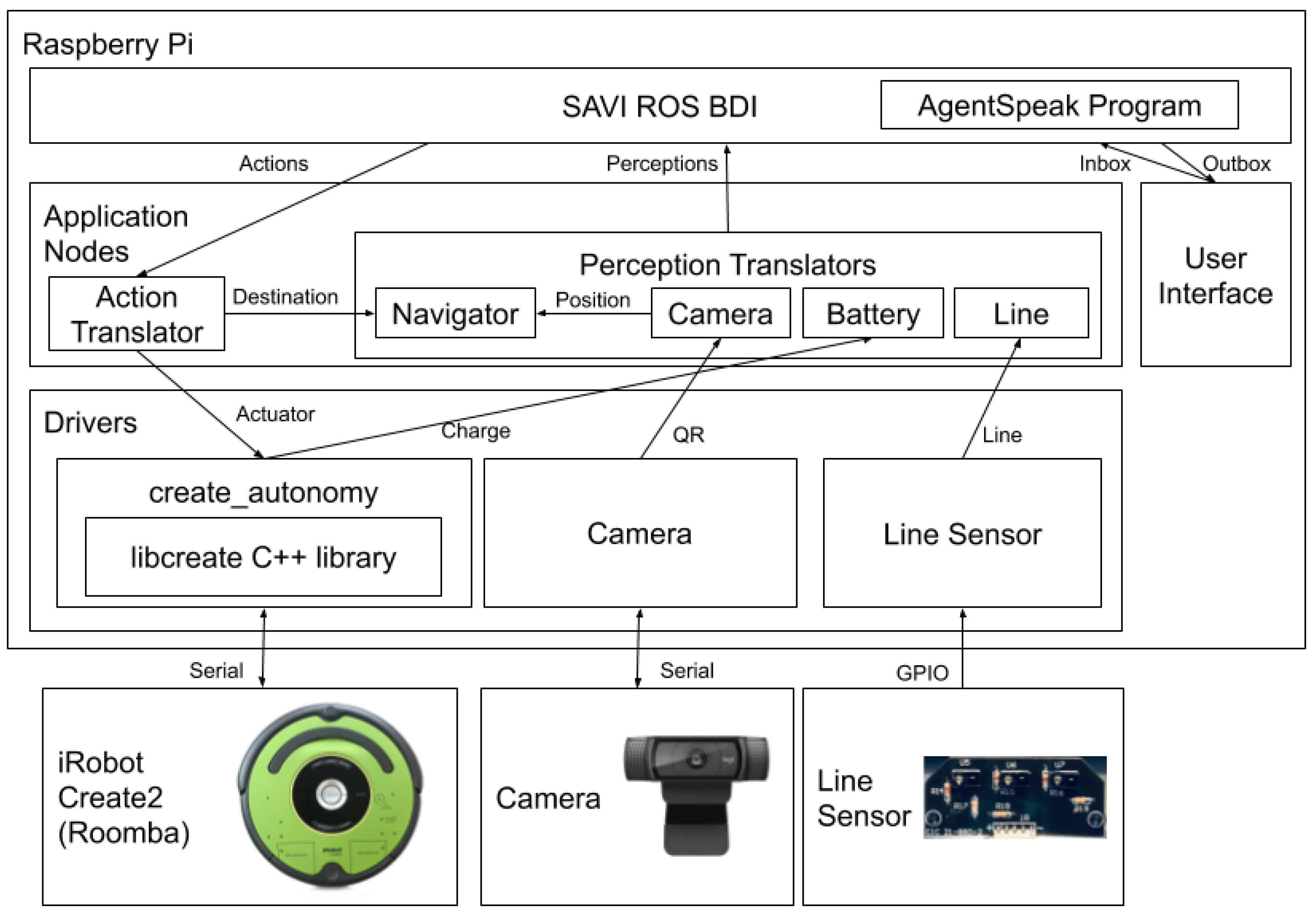
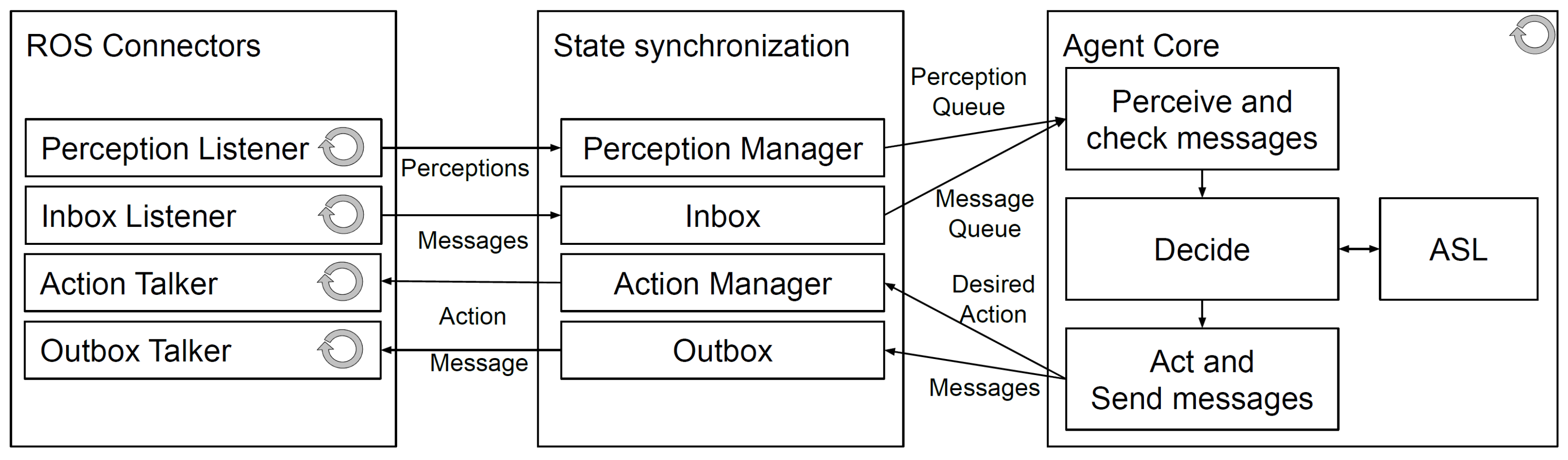
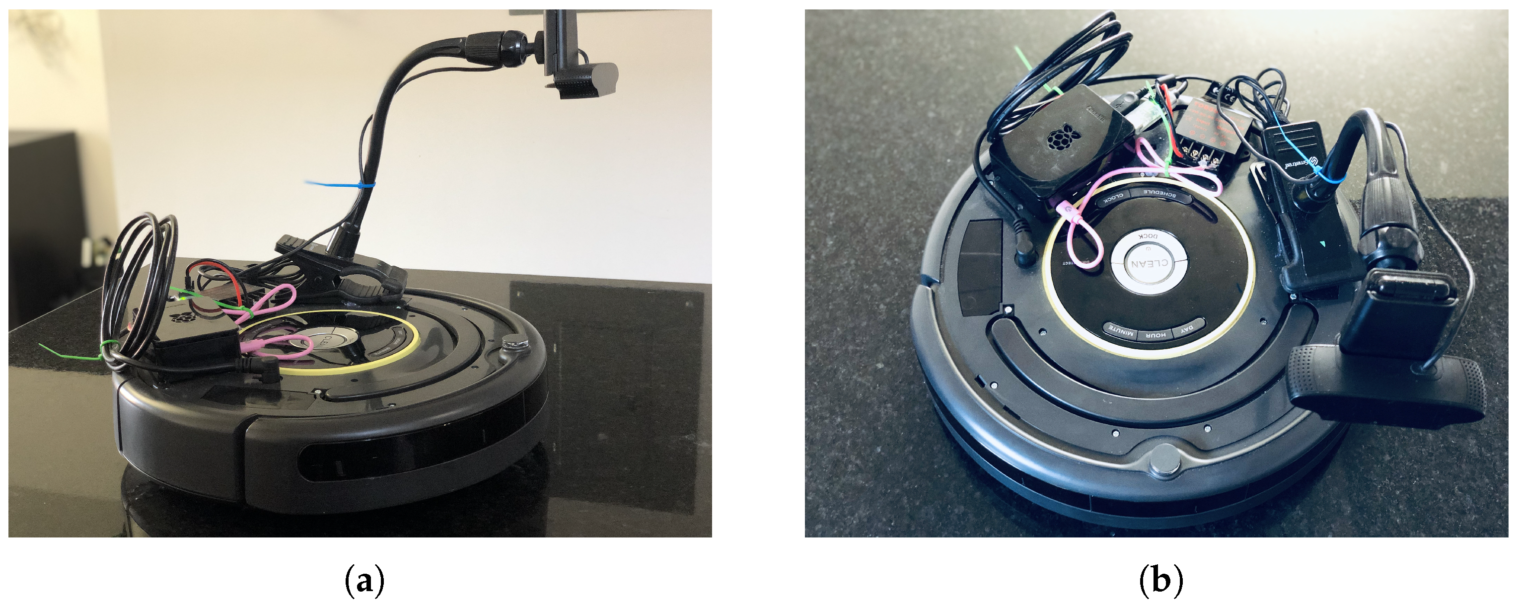
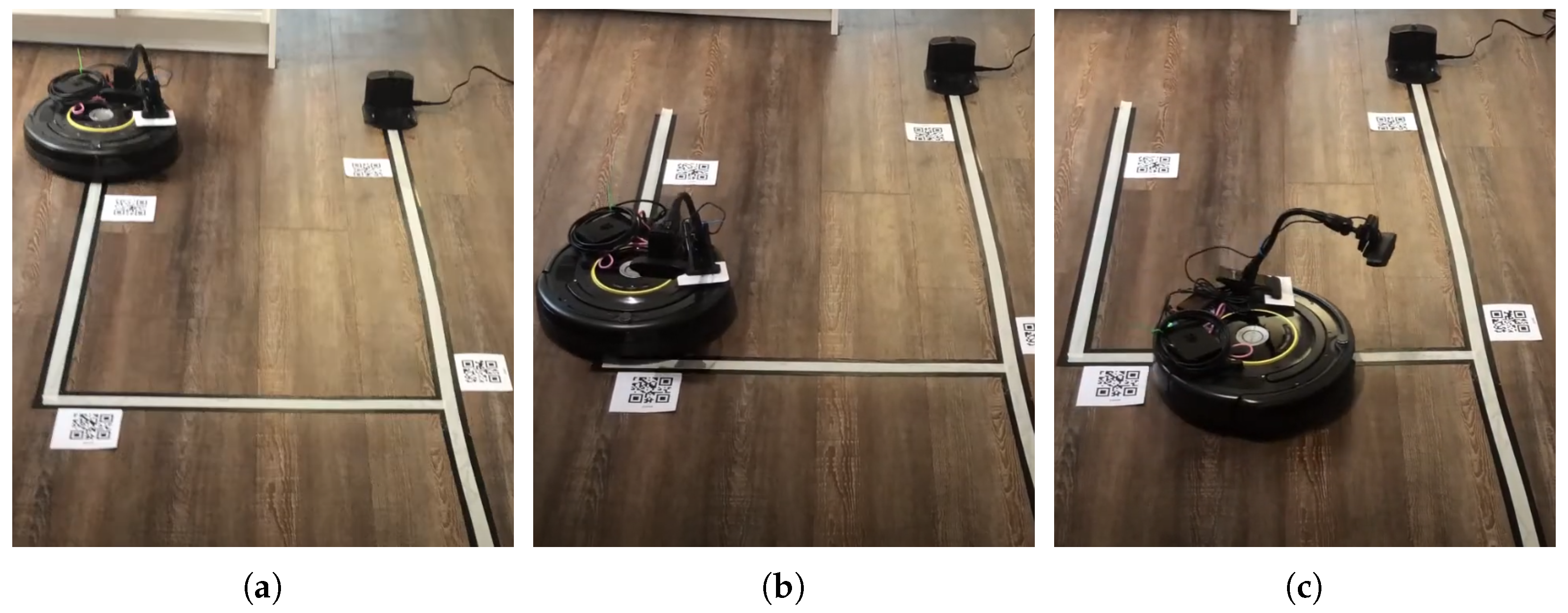
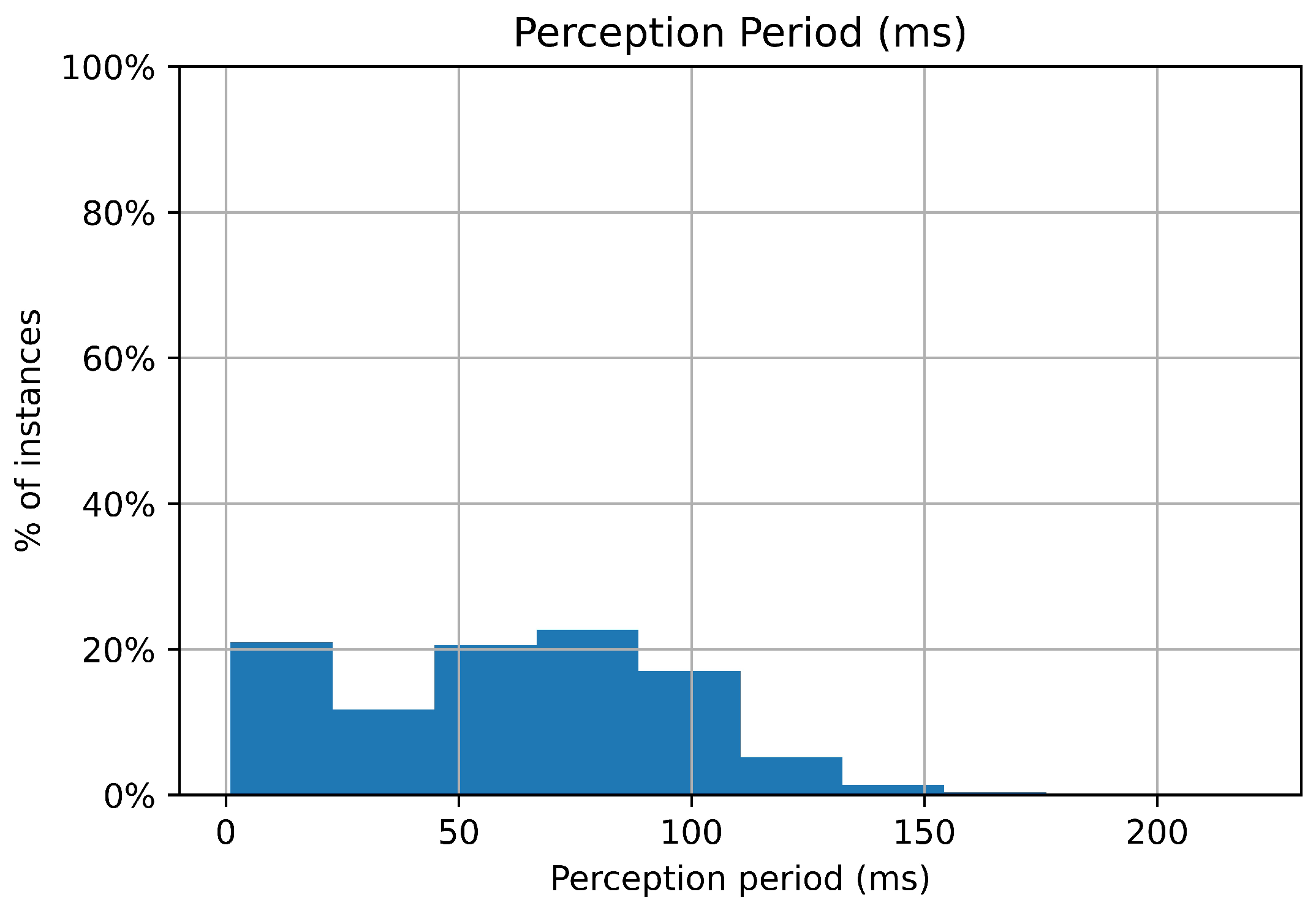
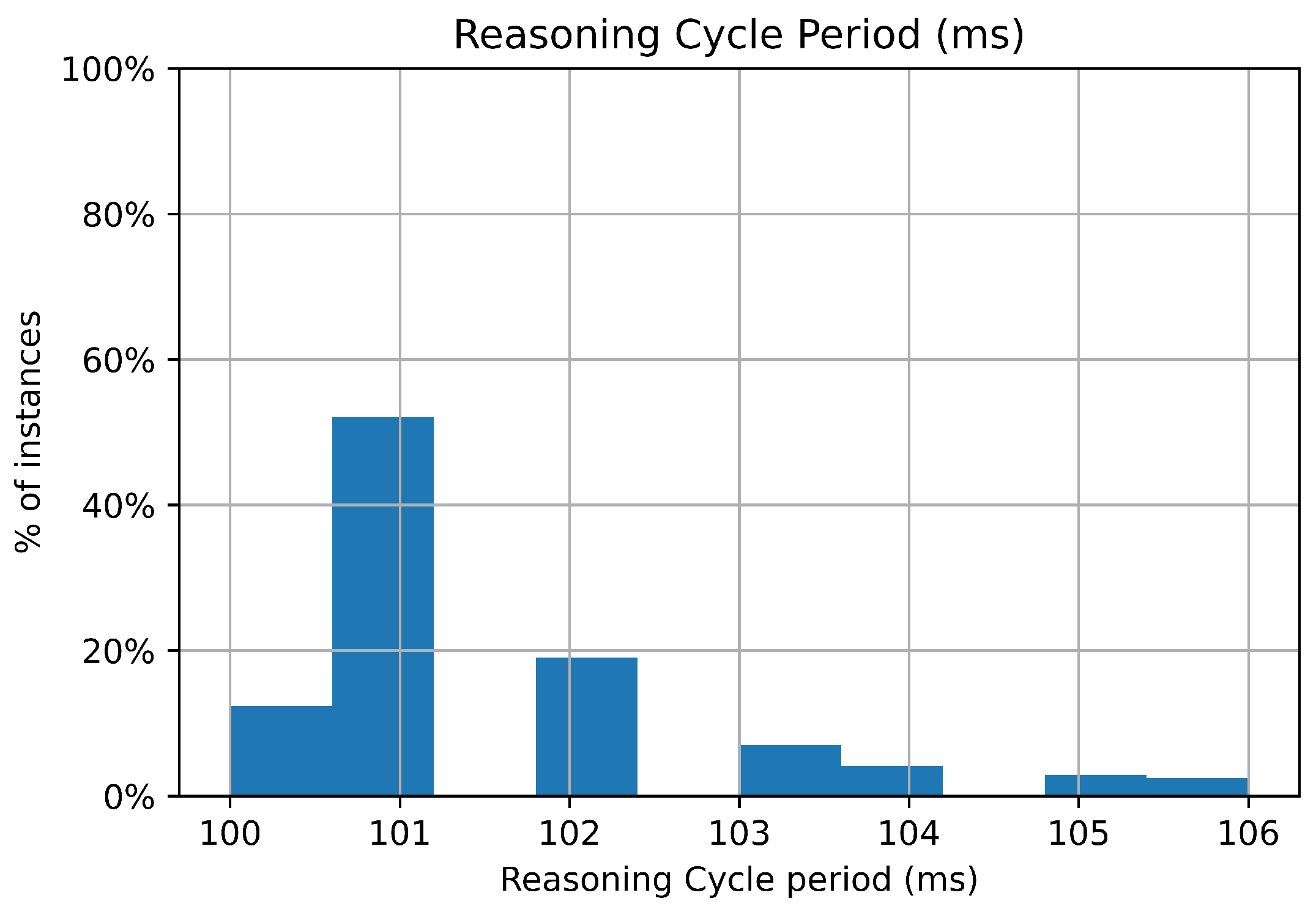
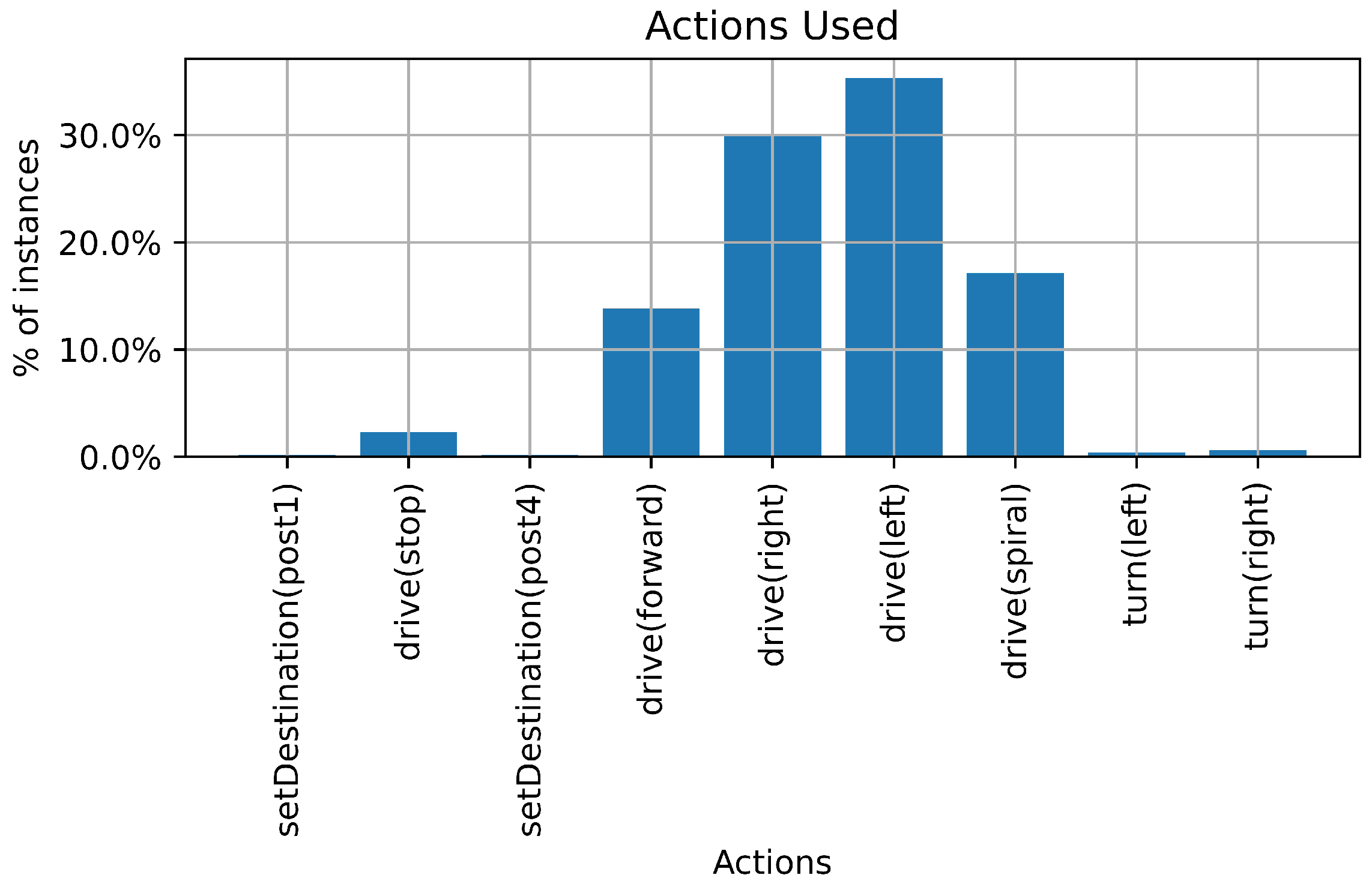
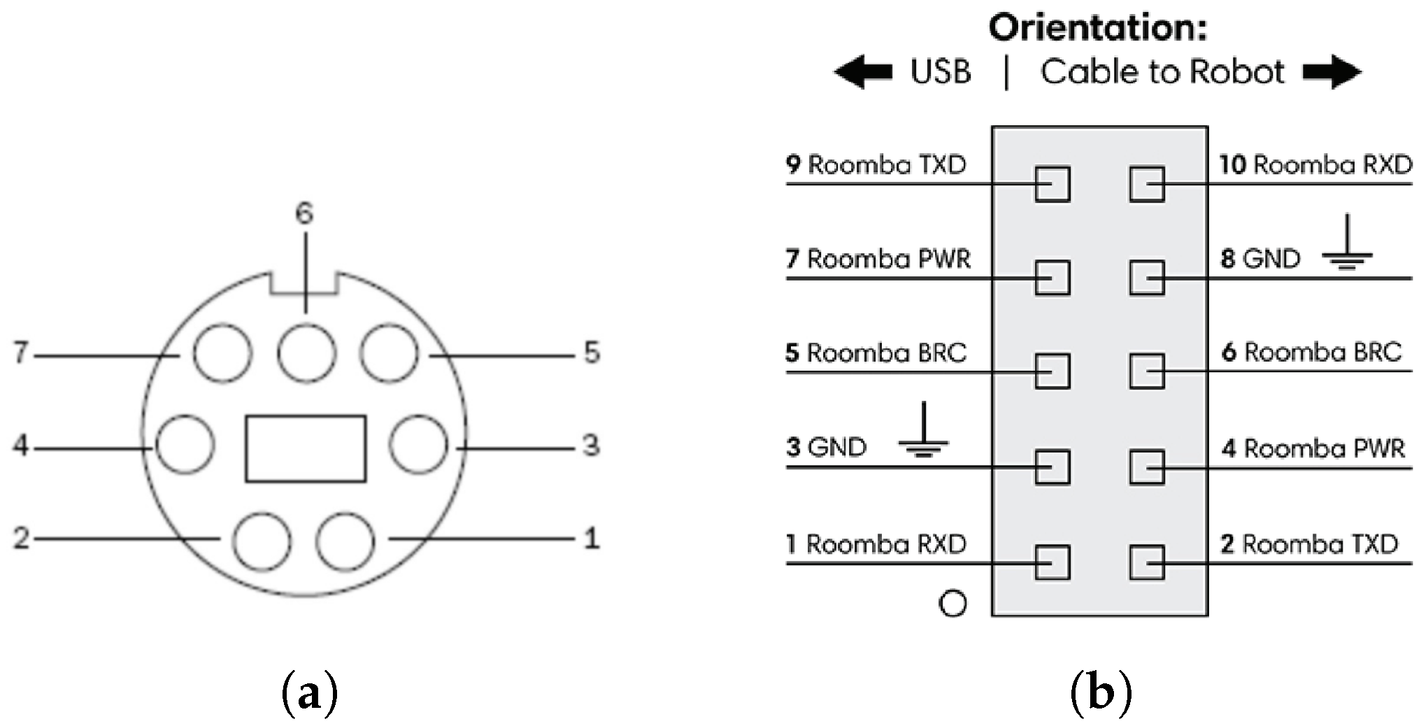
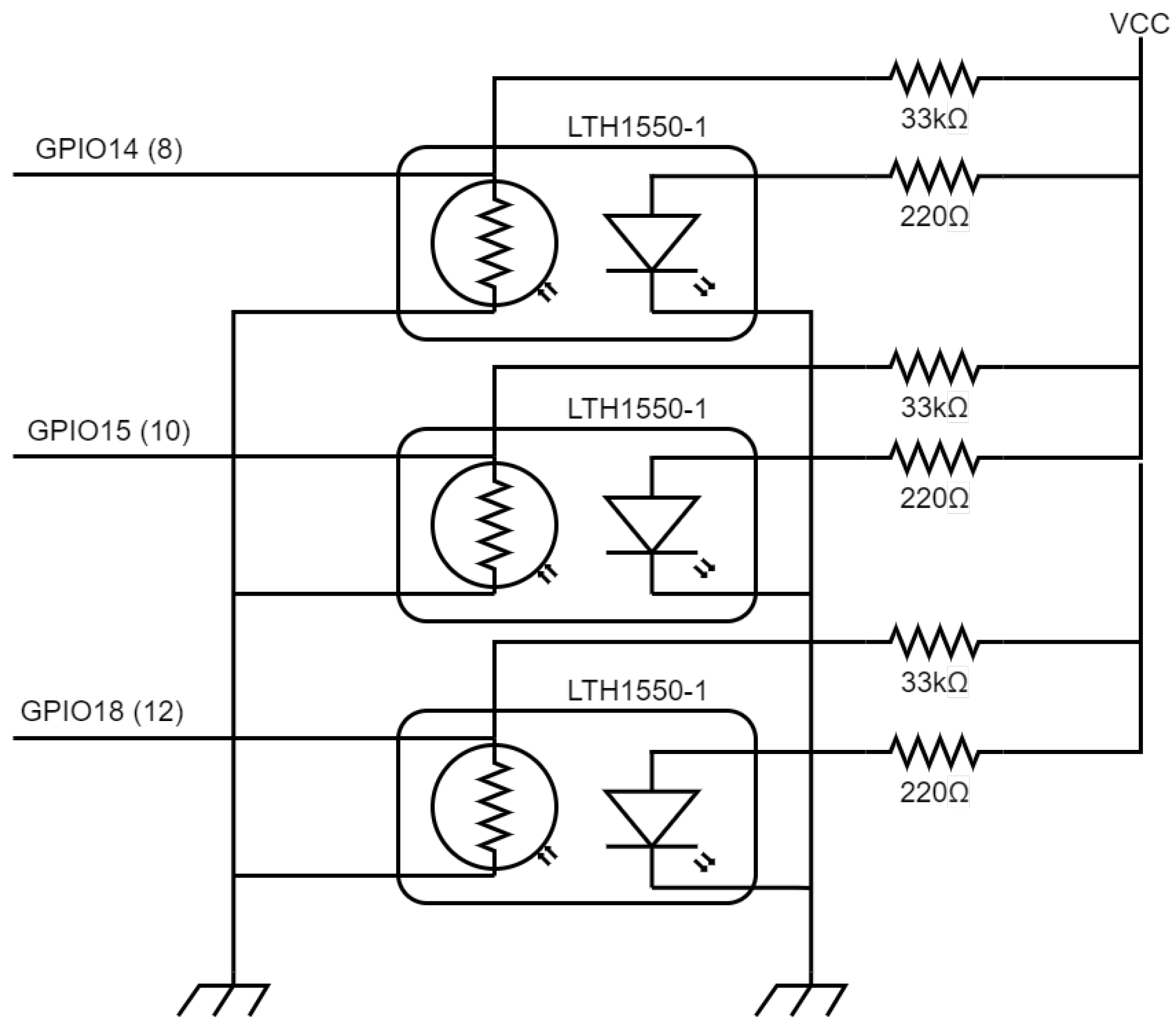
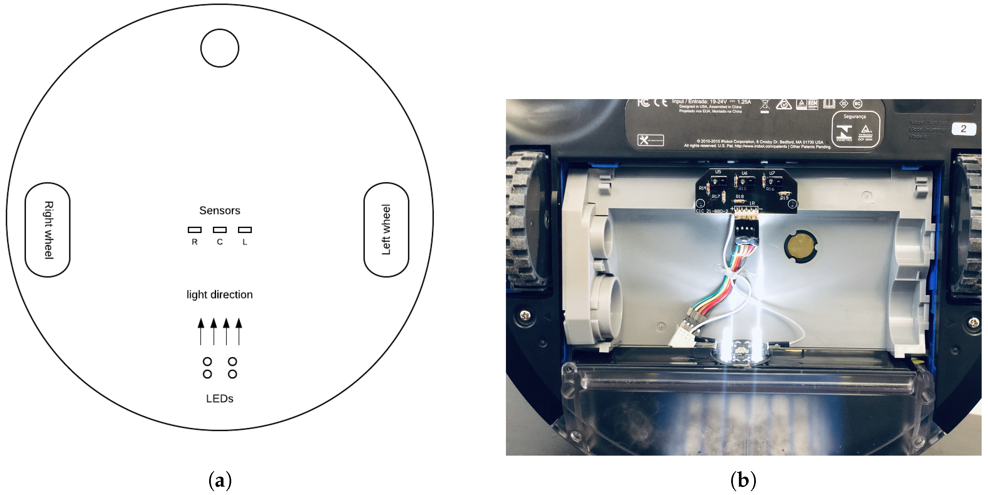
Table A1.
Create 2 external serial port RS232 connector pinout.
| Pin | Name | Description |
|---|---|---|
| 1 | Vpower | Battery + (unregulated) 16 V to 20 V |
| 2 | Vpower | Battery + (unregulated) 16 V to 20 V |
| 3 | RXD | 0V–5V Serial input to robot |
| 4 | TXD | 0V–5V Serial output from robot |
| 5 | BRC | Baud rate change |
| 6 | GND | Battery ground |
| 7 | GND | Battery ground |
Although this pinout provides access to the robot’s power supply, it must be converted from 16 V to 20 V to the regulated 5 V required by the Raspberry Pi computer via its USB-C connector or its GPIO pin. To get a stable 5 V for our Raspberry Pi, we used a Tobsun 15 W DC to DC power converter by feeding power to its input (12 V/24 V positive and negative) terminal from pin 4 and pin 3 of the Serial to USB header described in Figure A1b respectively. We connected the exposed wires of an improvised USB type C cable to the converter and then we plugged in the cable to the Raspberry Pi; when the RS232 end of the Serial-to-USB cable is plugged into the Create2 robot, the entire system is powered successfully.
Appendix A.2. Line Sensor Implementation
As our robot operates in an indoor environment without the support of GNSS systems for navigation, a simple means of moving through the tunnels and navigation was required. As an initial implementation, a line sensor was used for the robot to follow lines on the tunnel floor. This sensor is implemented using three Photointerrupter LTH 1550-01 diodes, shown in Figure A2. Each sensor detects if the line is on the left, center or right of the robot’s center. Two resistors were used per Photointerrupter, a 220 and a 33 . The 220 was used as a limiting resistor for the LED within the sensor and the 33 as a voltage divider to enable us to measure the voltage across the resistor when light falls on the phototransistor.
Figure A2.
Line sensor circuit.

The sensors were connected to three different GPIO pins on the Raspberry Pi. The right sensor is connected to GPIO14 (pin8), the center sensor to GPIO15 (pin10) and the left sensor to GPIO18 (pin12). The sensor is powered from the Raspberry Pi; the VCC pins are connected together and then to the 5 V pin of the Raspberry Pi, while the ground (GND) pins are connected together and then to the ground (GND) pin of the Raspberry Pi. When light falls on each of these sensors, their GPIO pins are set to HIGH, and when the sensors are covered or faced with a non-reflective material or has no light falling on them, their GPIO pins are set to LOW.
The navigation track was designed using a reflective tape, so that when it is faced by any of the sensors, the respective GPIO pin is set to HIGH, and then it is known if the line is on the right, center or left depending on the pin that was set to HIGH or LOW. The sensors are mounted under the center of the Create2, in line with the right and left wheels, as seen in Figure A3a. An image of the underside of the robot itself is provided in Figure A3b. This is to ensure more navigation accuracy, because if the sensors are mounted in front, or behind the wheels, the line would be detected before or after the robot needs to make a navigation decision. For example, if the sensors are mounted in front of the wheels, and while the robot is in motion (following the line) the line changes direction; the change in direction is detected first by the sensors making the robot to turn and change its direction before it needs to, thereby making it go out of track.
Figure A3.
Layout of the underside of the robot. (a): robot base layout; (b): under the robot.

The robot has a broad surface area and when on the floor, has little or no light underneath it. Since our sensors are mounted under the robot, they cannot function effectively because they need a certain amount of light in order to detect the line. A light source under the robot using four LEDs was added. These LEDs were mounted perpendicular to the sensors with their light directed at the sensor. With this in place, when the robot is on the floor, the light bounces off any reflective object or material placed on the floor and is absorbed by non-reflective materials or objects.
The line tracks are created using tapes. To ensure enough contrast between the line to follow and the floor regardless of the environment, we had to create a track with two different types of tape, reflective and non-reflective, with the non-reflective tape in the center. This type of line track would work irrespective of location flooring. The robot is kept on the track, with the center sensor on the non-reflective tape, so when any of the sensors is faced with the non-reflective tape, we know the line track is in that direction.
References
- Bordini, R.H.; Hübner, J.F.; Wooldridge, M. Programming Multi-Agent Systems in AgentSpeak Using Jason; Wiley Series in Agent Technology; John Wiley & Sons, Inc.: Hoboken, NJ, USA, 2007. [Google Scholar] [CrossRef]
- Brooks, R. A robust layered control system for a mobile robot. IEEE J. Robot. Autom. 1986, 2, 14–23. [Google Scholar] [CrossRef] [Green Version]
- Wooldridge, M. An Introduction to MultiAgent Systems, 2nd ed.; Wiley Publishing: Hoboken, NJ, USA, 2009. [Google Scholar]
- Chong, H.Q.; Tan, A.H.; Ng, G.W. Integrated cognitive architectures: A survey. Artif. Intell. Rev. 2009, 28, 103–130. [Google Scholar] [CrossRef]
- Bratman, M. Intention, Plans, and Practical Reason; Harvard University Press: Harvard, MA, USA, 1987; Volume 10. [Google Scholar] [CrossRef]
- Hübner, J.F.; Bordini, R.H. Jason: A Java-Based Interpreter for an Extended Version of AgentSpeak. Available online: http://jason.sourceforge.net (accessed on 16 February 2019).
- Open Source Robotics Foundation. ROS. Available online: https://www.ros.org/ (accessed on 27 May 2019).
- Wallis, P.; Ronnquist, R.; Jarvis, D.; Lucas, A. The automated wingman—Using JACK intelligent agents for unmanned autonomous vehicles. In Proceedings of the IEEE Aerospace Conference, Big Sky, MT, USA, 9–16 March 2002; Volume 5, p. 5. [Google Scholar] [CrossRef]
- Karim, S.; Heinze, C. Experiences with the Design and Implementation of an Agent-based Autonomous UAV Controller. In Proceedings of the Fourth International Joint Conference on Autonomous Agents and Multiagent Systems (AAMAS ’05), Utrecht, The Netherlands, 25–29 July 2005; ACM: New York, NY, USA, 2005; pp. 19–26. [Google Scholar] [CrossRef]
- Menegol, M.S.; Hübner, J.F.; Becker, L.B. Evaluation of Multi-agent Coordination on Embedded Systems. In Advances in Practical Applications of Agents, Multi-Agent Systems, and Complexity: The PAAMS Collection; Demazeau, Y., An, B., Bajo, J., Fernández-Caballero, A., Eds.; Springer International Publishing: Cham, Sweitzerland, 2018; pp. 212–223. [Google Scholar]
- Menegol, M.S. UAVExperiments. Available online: https://github.com/msmenegol/UAVExperiments (accessed on 24 May 2019).
- Boissier, O.; Bordini, R.H.; Hübner, J.F.; Ricci, A.; Santi, A. JaCaMo Project. Available online: http://jacamo.sourceforge.net/ (accessed on 16 May 2019).
- Menegol, M.S. vooAgente4Wp. Available online: https://drive.google.com/file/d/0B7EcHgES6He8VEtwR0xPZjdBbk0/view (accessed on 8 May 2019).
- Rezende, G.; Hubner, J.F. Jason-ROS. Available online: https://github.com/jason-lang/jason-ros (accessed on 24 May 2019).
- Rezende, G. MAS-UAV. Available online: https://github.com/Rezenders/MAS-UAV (accessed on 24 May 2019).
- Rezende, G. jason_ros. Available online: https://github.com/jason-lang/jason_ros/ (accessed on 13 October 2019).
- Morais, M.G. Rason. Available online: https://github.com/mgodoymorais/rason/tree/master/jason_ros (accessed on 17 July 2019).
- Calaça, I.; Krausburg, T.; Cardoso, R.C.; Bordini, R.H. JROS. Available online: https://github.com/smart-pucrs/JROS (accessed on 17 July 2019).
- Fichera, L.; Messina, F.; Pappalardo, G.; Santoro, C. A Python framework for programming autonomous robots using a declarative approach. Sci. Comput. Program. 2017, 139, 36–55. [Google Scholar] [CrossRef]
- Ledey, J.-P.; Thoreau, J. Eurobot: International Students Robotic Contest. Available online: http://www.eurobot.org/ (accessed on 15 July 2019).
- Pantoja, C.E.; Stabile, M.F.; Lazarin, N.M.; Sichman, J.S. ARGO: An Extended Jason Architecture that Facilitates Embedded Robotic Agents Programming. In Engineering Multi-Agent Systems; Baldoni, M., Müller, J.P., Nunes, I., Zalila-Wenkstern, R., Eds.; Springer International Publishing: Cham, Switzerland, 2016; pp. 136–155. [Google Scholar]
- Lazarin, N.M.; Pantoja, C.E. A robotic-agent platform for embedding software agents using raspberry pi and arduino boards. In Proceedings of the 9th Software Agents, Environments and Applications School (WESAAC), Niterói, Brazil, 1–3 June 2015. [Google Scholar]
- Alzetta, F.; Giorgini, P. Towards a Real-Time BDI Model for ROS 2. In Proceedings of the 20th Workshop “From Objects to Agents”, Parma, Italy, 26–28 June 2019; Volume 2404, pp. 1–7. [Google Scholar]
- ElDivinCodino. ROS2BDI. Available online: https://github.com/ElDivinCodino/ROS2BDI (accessed on 29 June 2020).
- Dennis, L.; Aitken, J.; Collenette, J.; Cucco, E.; Kamali, M.; McAree, O.; Shaukat, A.; Atkinson, K.; Gao, Y.; Veres, S.; et al. Agent-based autonomous systems and abstraction engines: Theory meets practice. In Proceedings of the 17th Annual Conference, TAROS 2016, Sheffield, UK, 26 June–1 July 2016. [Google Scholar]
- Cardoso, R.C.; Ferrando, A.; Dennis, L.A.; Fisher, M. An Interface for Programming Verifiable Autonomous Agents in ROS. In Proceedings of the European Conference on Multi-Agent Systems (EUMAS), Thessaloniki, Greece, 14–15 September 2020. [Google Scholar]
- Davoust, A.; Gavigan, P.; Ruiz-Martin, C.; Trabes, G.; Esfandiari, B.; Wainer, G.; James, J. An Architecture for Integrating BDI Agents with a Simulation Environment. In Engineering Multi-Agent Systems; Dennis, L.A., Bordini, R.H., Lespérance, Y., Eds.; Springer International Publishing: Cham, Switzerland, 2020; pp. 67–84. [Google Scholar]
- Davoust, A.; Gavigan, P.; Ruiz-Martin, C.; Trabes, G.; Esfandiari, B.; Wainer, G.; James, J. Simulated Autonomous Vehicle Infrastructure. Available online: https://github.com/NMAI-lab/SAVI (accessed on 19 February 2019).
- iRobot. iRobot Create2 Open Interface (OI) Specification Based on the iRobot Roomba 600. Available online: https://www.irobotweb.com/-/media/MainSite/Files/About/STEM/Create/2018-07-19_iRobot_Roomba_600_Open_Interface_Spec.pdf (accessed on 8 March 2020).
- Kohler, D.; Queiro, Q.; Corbellini, E. rosJava. Available online: http://wiki.ros.org/rosjava (accessed on 9 March 2020).
- Gavigan, P. savi_ros_bdi. Available online: https://github.com/NMAI-lab/savi_ros_bdi (accessed on 9 March 2020).
- Perron, J. create_autonomy. Available online: http://wiki.ros.org/create_autonomy (accessed on 8 March 2020).
- Gavigan, P.; Onyedinma, C. saviRoomba. Available online: https://github.com/NMAI-lab/saviRoomba (accessed on 9 May 2020).
- Logitech. c920-pro-hd-webcam-refresh.png. Available online: https://assets.logitech.com/assets/65478/3/c920-pro-hd-webcam-refresh.png (accessed on 9 March 2020).
- Onyedinma, C. SAVI_Roomba_App. Available online: https://github.com/NMAI-lab/SAVI_Roomba_App (accessed on 9 May 2020).
- Jrialland. Python-Astar. Available online: https://github.com/jrialland/python-astar (accessed on 24 August 2020).
- Gavigan, P. jasonDebuggingToolsaviRoomba. Available online: https://github.com/NMAI-lab/jasonDebuggingTool (accessed on 8 October 2020).
- Gavigan, P. saviRoombaDebugger. Available online: https://github.com/NMAI-lab/saviRoombaDebugger (accessed on 8 October 2020).
- Onyedinma, C.; Gavigan, P. Mail Delivery Robot Using BDI (Towards Campus Mail Delivery). Available online: https://youtu.be/cb63NFc24P0 (accessed on 24 August 2020).
- iRobo.iRobot Create Cable Pinout. Available online: https://www.irobot.com/-/media/mainsite/pdfs/about/stem/create/create2-cablepinout2018.ashx (accessed on 8 May 2019).
Figure 1.
Mail delivery robot hardware.

Figure 4.
Assembled robot prototype (side view: (a), top view: (b)).

Figure 5.
Map of the test environment.

Figure 6.
Demo of robot operation, video available at [39]. (a): mail collected; (b): detecting post point; (c): turned to continue; (d): interrupt delivery to charge battery; (e): charge battery; (f): proceed to destination.
Figure 6.
Demo of robot operation, video available at [39]. (a): mail collected; (b): detecting post point; (c): turned to continue; (d): interrupt delivery to charge battery; (e): charge battery; (f): proceed to destination.


Figure 7.
Perception period.

Figure 8.
Processing time of the agent reasoning cycle.

Figure 9.
Plan frequency.

Figure 10.
Action frequency.

Publisher’s Note: MDPI stays neutral with regard to jurisdictional claims in published maps and institutional affiliations. |
© 2020 by the authors. Licensee MDPI, Basel, Switzerland. This article is an open access article distributed under the terms and conditions of the Creative Commons Attribution (CC BY) license (http://creativecommons.org/licenses/by/4.0/).
Share and Cite
MDPI and ACS Style
Onyedinma, C.; Gavigan, P.; Esfandiari, B. Toward Campus Mail Delivery Using BDI. J. Sens. Actuator Netw. 2020, 9, 56. https://0-doi-org.brum.beds.ac.uk/10.3390/jsan9040056
AMA Style
Onyedinma C, Gavigan P, Esfandiari B. Toward Campus Mail Delivery Using BDI. Journal of Sensor and Actuator Networks. 2020; 9(4):56. https://0-doi-org.brum.beds.ac.uk/10.3390/jsan9040056
Chicago/Turabian StyleOnyedinma, Chidiebere, Patrick Gavigan, and Babak Esfandiari. 2020. "Toward Campus Mail Delivery Using BDI" Journal of Sensor and Actuator Networks 9, no. 4: 56. https://0-doi-org.brum.beds.ac.uk/10.3390/jsan9040056
Note that from the first issue of 2016, this journal uses article numbers instead of page numbers. See further details here.