Is Barocaloric an Eco-Friendly Technology? A TEWI Comparison with Vapor Compression under Different Operation Modes


1
Department of Industrial Engineering, University of Salerno, Via Giovanni Paolo II 132, 84084 Fisciano (SA), Italy
2
Department of Industrial Engineering, University of Naples Federico II, P.le Tecchio 80, 80125 Napoli, Italy
*
Author to whom correspondence should be addressed.
Climate 2019, 7(9), 115; https://0-doi-org.brum.beds.ac.uk/10.3390/cli7090115
Submission received: 31 July 2019
/
Revised: 3 September 2019
/
Accepted: 13 September 2019
/
Published: 18 September 2019
(This article belongs to the Special Issue Environment Pollution and Climate Change)
Abstract
:Barocaloric is a solid-state not-in-kind technology, for cooling and heat pumping, rising as an alternative to the vapor compression systems. The former is based on solid-state refrigerants and the latter on fluid ones. The reference thermodynamical cycle is called active barocaloric regenerative refrigeration (or heat pumping cycle). The main advantage of this technology is to not employ greenhouse gases, which can be toxic or damaging for the environment and that can contribute to increasing global warming. In this paper, the environmental impact of barocaloric technology was evaluated through a Total Equivalent Warming Impact (TEWI) analysis carried out with the help of a numerical 2D model solved through a finite element method. Specifically, we propose a wide investigation on the environmental impact of barocaloric technology in terms of TEWI index, also making a comparison with a vapor compression plant. The analysis focuses on both the cooling and heat pump operation modes, under different working conditions and auxiliary fluids. The results revealed that a barocaloric system based on ABR cycle could provide a reduction of the environmental impact with respect to a vapor compression system. The addition of nanofluids contributes in reducing the environmental impact up to −62%.
1. Introduction
Barocaloric belongs to the solid-state not-in-kind (NIK) [1,2,3] caloric technologies for cooling and heat pumping that are rising because of their prerogative of employing solid-state materials as refrigerants [4,5,6]. The solid-state nature of the refrigerants avoids that a system based on barocaloric cooling or heat pumping could contribute in the accidental release of refrigerants in the atmosphere, contrary to what happens with vapor compression whose refrigerants have a fluid nature. Barocaloric is counted among the caloric cooling and heat pumping class of technologies, all having the common denominator of being based on solid-state refrigerants exhibiting a caloric effect [7] (magnetocaloric, electrocaloric, elastocaloric and barocaloric effect, in dependence of the nature of the external stimulus) [8,9,10,11,12,13].
Barocaloric technology employs solid-state barocaloric materials whose name derives by the effect they experiment, called barocaloric effect (BCE). BCE occurs as a solid-state transformation generated by a variation of the hydrostatic pressure of the system [14]. Such transformation could provoke an isothermal entropy change (∆ST) or an adiabatic temperature variation (∆Tad) in the barocaloric material, despite of the isothermal or adiabatic nature of the process.
The reference thermodynamical cycle of barocaloric cooling and heat pumping is called Active Barocaloric Regenerative refrigeration (ABR) (or heat pumping) cycle. It is applied to an active barocaloric regenerator in which the barocaloric material is both refrigerant and regenerator. Such structure undergoes four consecutive processes that are cycled with the aim of subtracting heat from a cold environment and to reject it in a hot one. The transfer of the heat fluxes is entrusted to an auxiliary fluid that crosses the caloric regenerator. The auxiliary fluid, defined as Heat Transfer Fluid (HTF), could be constituted by water, water ethylene glycol or by optimizing solutions for enhancing the heat transfer, such as nanofluids [15,16,17].
The main advantage of this technology is to not employ greenhouse gases, that can result toxic or damaging for the environment and that can contribute to increase global warming [18,19]. Furthermore, it can operate with small level of noise and it exhibits the potential of recycling its components. All these points confer to barocaloric refrigeration and heat pumping the role of potentially become a real alternative to the conventional vapor compression refrigeration [20].
Most of the systems employed nowadays are based on the vapor compression technique, which has been the center of attention since 1987, when the Montreal Protocol [21] was issued, because of the environmental impact associated to the refrigerants employed, causing ozone depletion and global warming. Over the years, subsequent measures were taken with the Kyoto Protocol [22] in 1997 and the following amendments up to the Kigali amendment [23], held in 2016. In all these years we have witnessed an evolution of refrigerants: ChloroFluoroCarbons (CFCs), HydroChloroFluoroCarbons (HCFCs), HydroFluoroCarbons (HFCs), HydroFluoroOlefins (HFOs), natural fluids [24,25,26,27]. They are devoted to vapor compression-based refrigeration and heat pumping but, more than just an evolution, we would like the world of fluid-state refrigerants to undergo a revolution [28].
The investigation introduced in this paper will be contextualized in the common goal of reducing both the energy consumption and the environmental impact of the nowadays employed systems. The main parameter to evaluate global warming impact and carbon-dioxide emissions coming out from a cooler is the total environmental warming impact (TEWI) index [29,30,31], which takes into account both the direct and indirect contributions produced. Scientific literature accounts only a small number of investigations on the environmental impact of caloric systems [18,19].
In this context we propose a wide investigation on the environmental impact of barocaloric technology in terms of TEWI index and we also make a comparison with a vapor compression plant. The analysis focuses on both the cooling and heat pump operation modes, under different working conditions and auxiliary fluids.
2. The Active Barocaloric Technology for Cooling and Heat Pumping
The reference thermodynamical cycle of barocaloric cooling and heat pumping, called ABR cycle, could be conceived as refrigeration or heat pumping cycle, depending on the desired operation mode of the system.
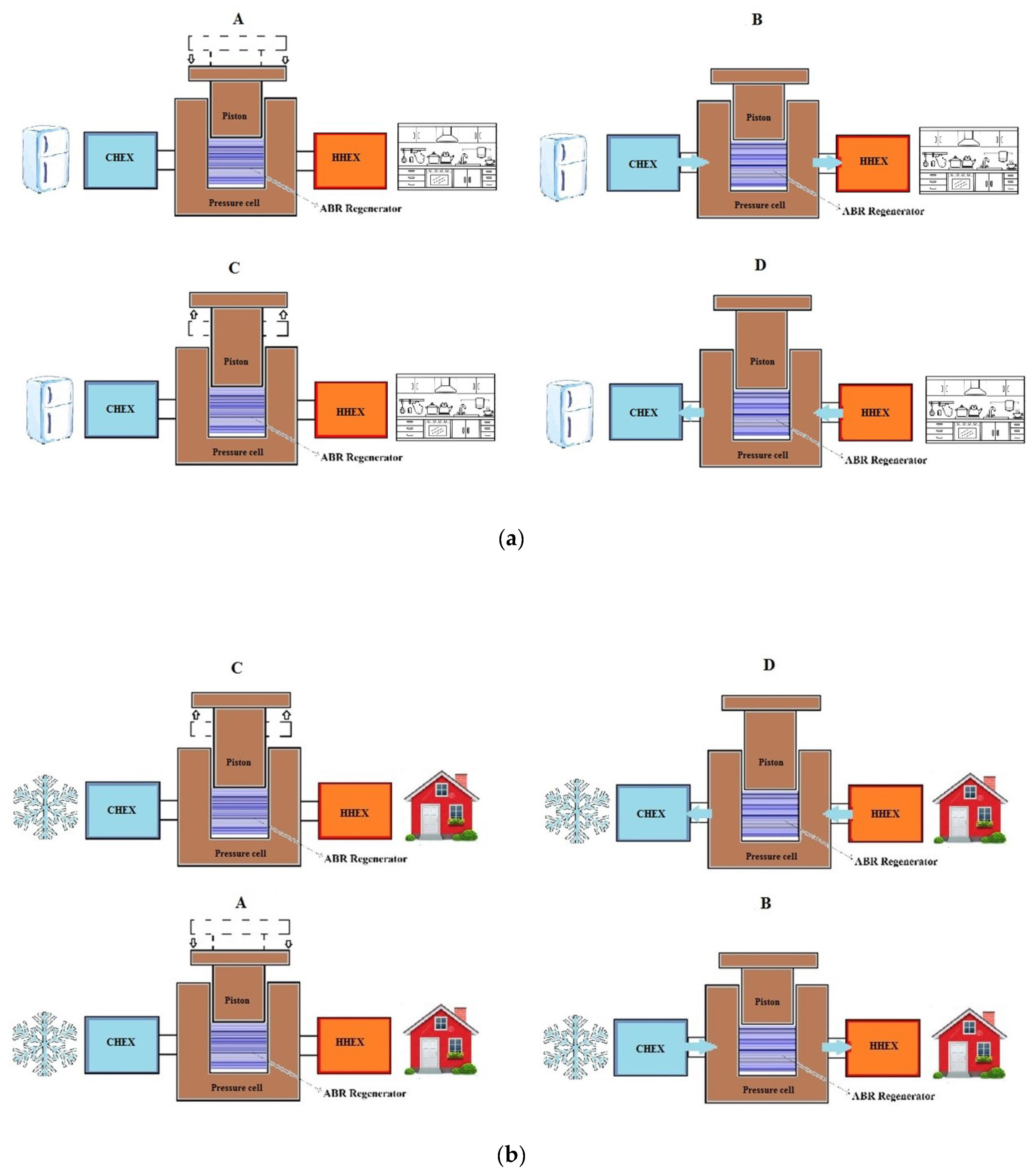
The cycle is composed of four steps, reported in Figure 1. Specifically, Figure 1 shows the four processes forming the active barocaloric regenerative cycle for: (a) cooling and (b) heat pumping operation-modes. In (A) the hydrostatic pressure of the system grows adiabatically, causing an augmentation of the temperature of the material due to barocaloric effect. In (B) the heat transfer from cold-to-hot heat exchanger though the HTF flowing occurs. Subsequently, in (C) the hydrostatic pressure decreases adiabatically inducing a temperature-falling of the barocaloric material, following BCE. Finally, the hot-to-cold flow (D) cools down the HTF that, reaching the cold heat exchanger, subtracts heat; thus, the useful effect of the ABR cycle is generated, if the system is working in cooling mode. Dually, for heat pumping, the desired effect of the cycle occurs in step (B), when the fluid heats up because of cold-to-hot flowing where, reaching the hot heat exchanger, it adds heat to the environment to be warmed.
A two-dimensional model that reproduces the behavior of the active barocaloric regenerator was developed and experimentally validated in previous investigations [32,33,34]. The regenerator is designed as a parallel-plate structure [35], surrounded by a h × L packaging (20 × 45 mm2) containing 54 plates of barocaloric materials (0.25 mm thickness), stacking channels (0.125 mm thickness) where the HTF flows in both directions. Further details on the design of the regenerator and on the model are reported by Aprea et al. [35,36]. On the left side of the regenerator, by means of a first-type boundary condition, the presence of a cold heat exchanger (CHEX), having TC as set point temperature, is modelled. Dually, the same is done on the right side where TH is the first-type condition associated to the hot heat exchanger (HHEX). The mathematical system that regulates the 2D model is composed by the following equations:
Equation (1), defining, respectively, the continuity of mass equation, the momentum equations of fluid (Navier-Stokes) and the fluid and solid energy equations, is imposed during the fluid flow processes. Laminar flow and incompressible fluid are assumed.
Equation (2) acts during the phases of adiabatic field increasing and decreasing. Since in these steps the fluid is not moving, Equation (2) is composed only by the fluid and the solid energy equations. In the solid energy equation, the temperature change due to barocaloric effect is included by means of the Q term, of which the expression is explicated in Equation (3). Equation (3) converts the adiabatic temperature change, due to barocaloric effect, in a power density. The term has dependence by the temperature of the caloric material and the external field applied to the system. The related mathematical function for Q was evaluated through a mathematical finder software, following the elaboration and the manipulation of experimental data of specific heat and ∆Tad of the barocaloric material, provided by the scientific community and published in open literature [37]. A complete description of all the steps followed by us in the Q terms building is reported by Aprea et al. [35,36]. Next to the construction and the manner of including Q in the field increasing/decreasing processes of the 2D model, we explained in details how we accounted the phenomenon of the thermal hysteresis that could become relevant for first order transition materials.
During the HTF flow processes the interaction among the regenerator and the cold and hot heat exchangers is entrusted to Dirichlet boundary conditions: In the cold-to-hot flow process, the CHEX mean temperature TC is imposed in the left side; in the hot-to-cold TH (HHEX mean temperature) is forced on the right side. During the steps of adiabatic pressure increasing/decreasing, the coupled boundary condition in this process is thermal insulation applied to all the boundaries.
The model is solved through finite element method (FEM). The ABR cycle was repeated cyclically many times until detecting the regenerator reaching the steady-state condition. The latter must satisfy the cyclicality criterion in every point of the active caloric regenerator:
3. Materials of the Investigation
3.1. Barocaloric Refrigerant
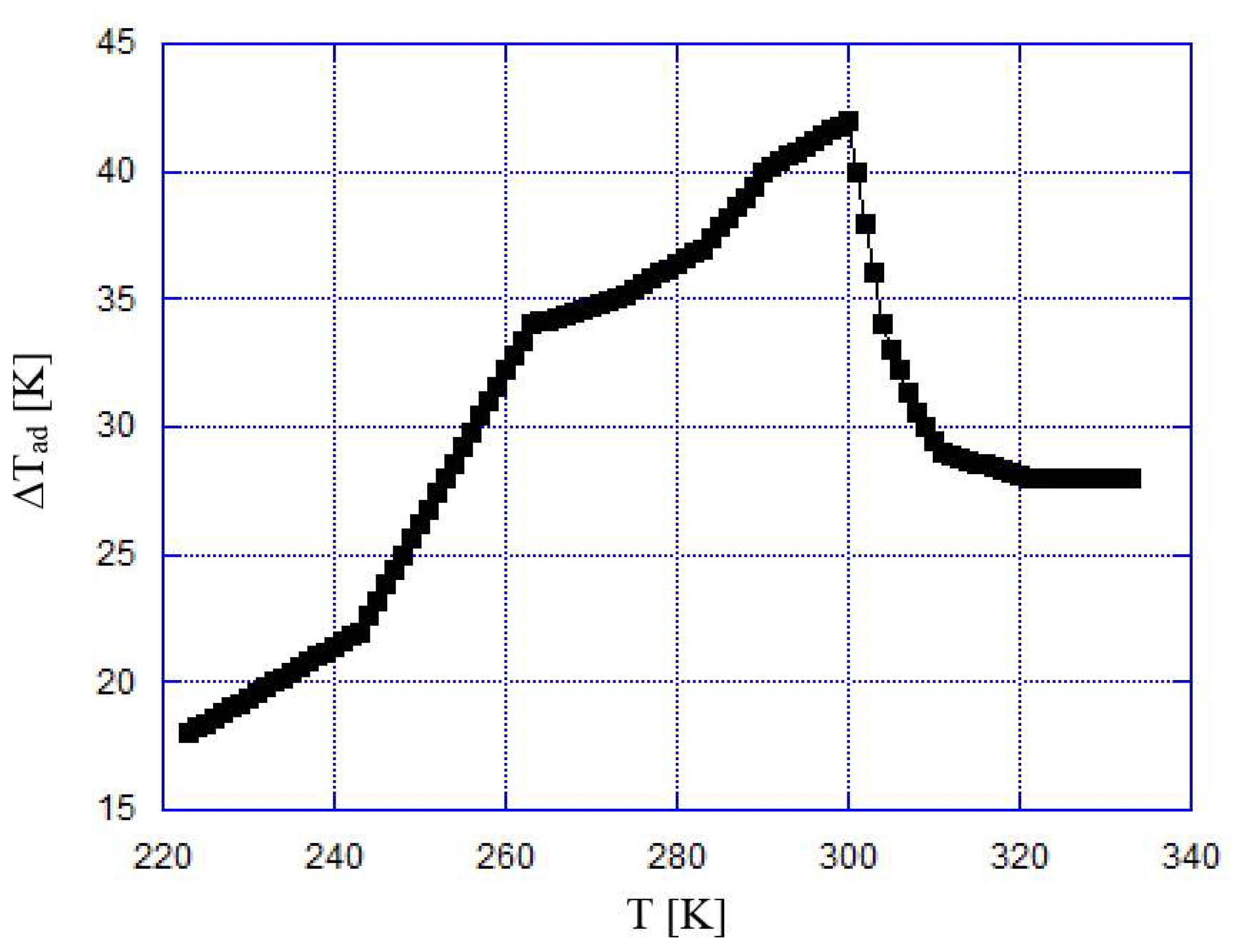
To the purpose of the investigation introduced we chose a barocaloric material that could result suitable as refrigerant for both the cooling and the heat pumping operation modes. Among the general requirements of moderate costs, easiness of synthesis, no-toxicity, there was the necessity of manifesting large values of ∆Tad in the working temperature range. Therefore, considering the temperature range devoted to cooling and heat pumping applications, we selected a barocaloric elastomer called acetoxy silicone rubber (ASR) [37] which belongs to the class of vulcanizing rubbers. The materials of this class can be reversibly stretched many times to their initial length upon moderately low applied pressures. Acetoxy silicone rubber made of polydimethylsiloxane, additive, preserving agent and fillers, exhibits a super-giant barocaloric effect with a peak of ∆Tad located in correspondence of the crystalline–amorphous transitions with the consequence of polymer chains rearrangements. Figure 2 reports the adiabatic temperature change detected in acetoxy silicone rubber during unloading process with ∆p = 0.390 GPa. The peak was 41.1 K in proximity of 298 K. This makes ASR eligible for both cooling (255 ÷ 290 K) and heat pumping (278 ÷ 298 K) working ranges. In Table 1 the thermodynamic properties of the ASR are summarized.
3.2. Auxiliary Fluids
The selection of the auxiliary fluids of the investigation is a crucial point. Based on the temperature working range, as preliminary choice we selected water and a 50%Ethylene-Glycol (EG)/50%water(W) mixture, addressed respectively to heat pumping (above 0 °C) and cooling (below 0 °C) operation modes. The freezing point of the 50%EG/50%W mixture is 236 K. The thermophysical properties of the above two fluids are provided by the American Society of Heating, Refrigerating and Air-Conditioning Engineers (ASHRAE) as table functions of the temperature [38]. These two fluids are the most commonly employed in caloric technology and therefore we deem they are significative for the purposes of the analysis introduced.
To enlarge the spectrum of the investigation, we decided to evaluate the environmental impact of barocaloric technology while the system mounts advanced HTF: The nanofluids [39,40,41,42,43,44,45]. Specifically, we tested variable concentrations of Al2O3-water nanofluids and of Cu-50%EG/50%W nanofluids, respectively, for heat-pumping and for cooling usages.
The thermophysical characteristics of the Al2O3 and Cu nanoparticles are listed in Table 2.
We considered different concentrations of nanoparticles dispersed on equal volume of base fluid as:
The thermophysical properties of the nanofluids are dependent on the volume fraction of nanofluids ; therefore, to include such dependence in the model, we adopted the following correlations available in scientific literature [46,47] (valid for both Al2O3-water and Cu-50%EG/50%W nanofluids):
The viscosity of the Al2O3-water nanofluids was modeled according to [46]:
The viscosity of the Cu-50%EG/50%W nanofluids was modeled following [48]:
4. The TEWI Analysis
The TEWI index is one of the most comprehensive ways to evaluate and quantify the environmental impact of refrigeration or heat pumping systems. Based on the concept that a refrigeration or heat pumping system is related to direct and indirect environmental impacts, TEWI accounts for both, combining the effect of direct refrigerant emission with the energy consumption and to the related combustion of fossil fuels for electric energy production. TEWI is calculated as:
Global warming potential (GWP) is an index employed to quantify the direct impact of greenhouse gases on global warming. It counts the mass of CO2 that would result in the same net impact on global warming as the release of a single unit (kg) of the atmospheric component in question.
The direct contribution (Equation (12)) to the TEWI index depends on the GWP of refrigerant fluids employed and on the fraction of refrigerant charge released into the atmosphere: it is mainly due to leakage during the operational plant lifetime (PL) and to the residual amounts, which, according to the current state of technology, are not recyclable and thus are released into the atmosphere when taking a plant out of operation (1-PR). In the simulation, PL is assumed to be 5%, whereas PR has not been considered. The barocaloric system does not exhibit a direct contribution to global warming since the caloric refrigerant has a solid state. The indirect contribution (Equation (13)) is due to the energy-related contribution. The literature provides some indicative average levels of CO2 release per kWh of electrical energy for various countries. For Italy, the value is 0.6 kg CO2/kWh.
5. The Operating Conditions of Investigation
The investigation was performed numerically through the 2D model introduced in Section 2. The barocaloric system was tested both in cooling and heat pumping operation modes.
During the cooling mode, the investigation was performed under the following operating conditions:
- the set point temperature range was 255 ÷ 290 K;
- the frequency of repeating ABR cycle was 1.25 Hz;
- the adiabatic variation of applied hydrostatic pressure was Δp = 0.390 GPa;
- the velocity of the HTF during the flowing phases varied by 0.04 ÷ 0.2 m/s;
- the nanoparticle volume fraction of the Cu-50%EG/50%W nanofluids was increased from 2% to 10%.
During the heat pumping operation mode, the following operating conditions were forced:
- the set point temperature range was 278 ÷ 298 K;
- the frequency of repeating ABR cycle was 1.25 Hz;
- the adiabatic variations of applied hydrostatic pressure were: Δp = 0.273 GPa and Δp = 0.390 GPa;
- the velocity of the HTF during the flowing phases varied by 0.15 ÷ 0.25 m/s;
- the nanoparticle volume fraction of the Al2O3-water nanofluids was increased from 2% to 10%.
6. Results
As a prerequisite to the results on the environmental impact, we report the COP of the barocaloric system evaluated for cooling and heat pumping modes, respectively, as:
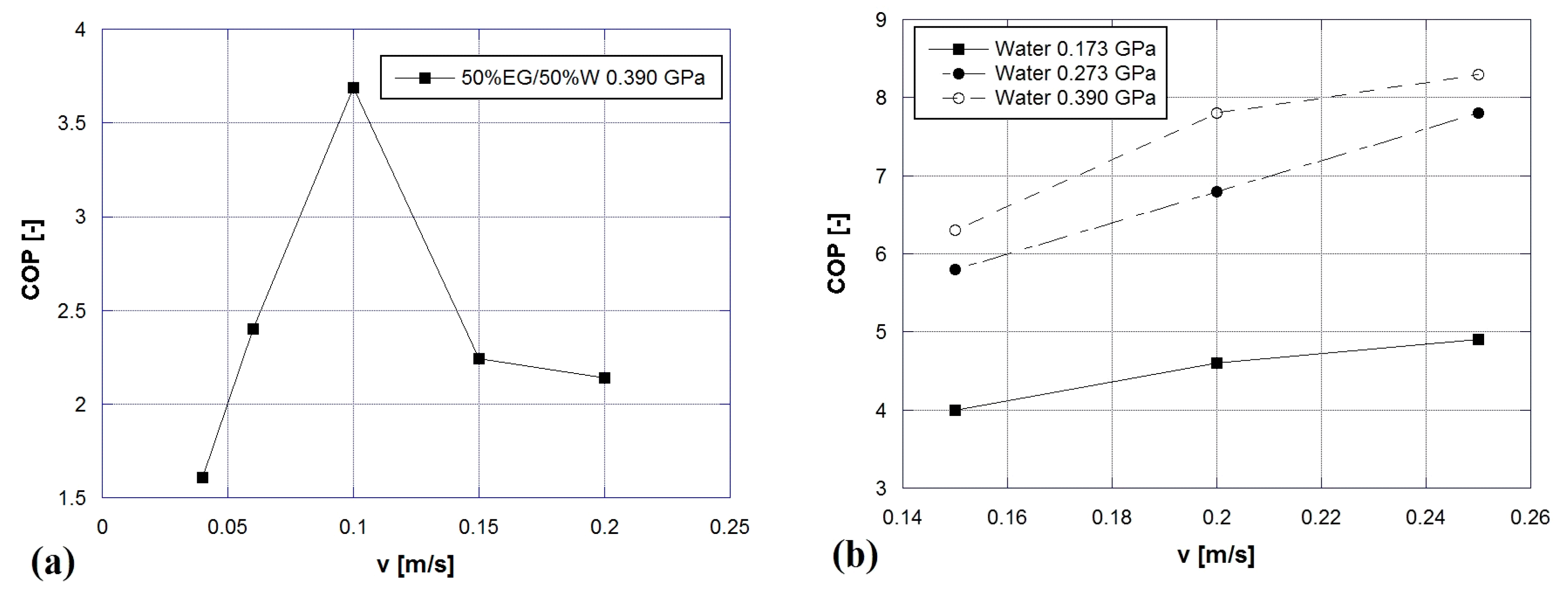
Figure 3 reports the coefficients of performance detected when the system works with common heat transfer fluids. Figure 3a shows the COP as a function of the velocity of the HTF (50%EG/50 W) while the system works with ASR under ∆p = 0.390 GPa. Figure 3b displays COP as a function of velocity of the auxiliary fluid (water) for different ∆p applied to the barocaloric material. The first set of data emerging shows that, even if they were detected under different working conditions, as expected, the COPhp values are greater than those of COPcool. Furthermore, one can notice that the optimal point is red shifting toward higher velocities when the system works in the heat pumping mode. The reason must be found in the mechanical power associated to the work of the pump (for fluid motion) that becomes much more predominant if the system and that employs an EG/W mixture, of which the viscosity is higher than that of water. Such an effect produces a deep knocking-down of the COPcool for v greater than 0.1 m/s.
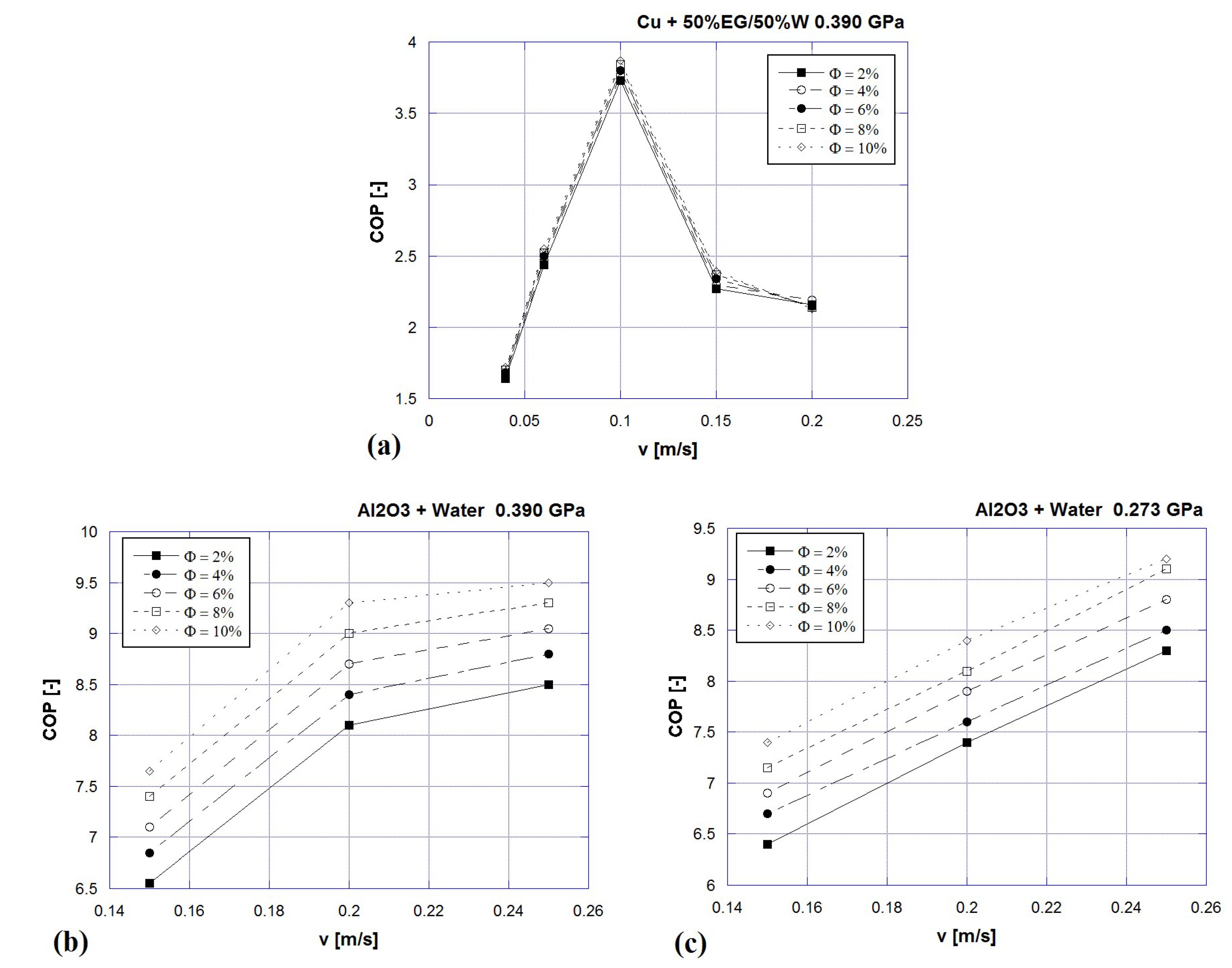
Figure 4 exhibits the coefficients of performance as a function of velocity when HTF is formed by nanofluids. In Figure 4a COP vs. fluid velocity is plotted when the system works in cooling mode employing ASR (0.390 GPa) and Cu + 50%EG/50%W nanofluids, as barocaloric refrigerant and HTF respectively. From Figure 4a one can observe that the addition of nanoparticles in the base fluid carries to COP increments up to +8.5% if φ grows till 10%. In Figure 4b,c, COP vs. HTF velocity is reported for the heat pumping mode where the auxiliary fluid is Al2O3 + water and the solid-state refrigerant (ASR) operates under two different pressure ranges (∆p = 0.273 GPa and ∆p = 0.390 GPa). The addition of Al2O3 + water nanofluids in an active barocaloric heat pump working with acetoxy silicone rubber under ∆p = 0.390 GPa provides a COP increment up to 19.2% registered at φ = 10%.
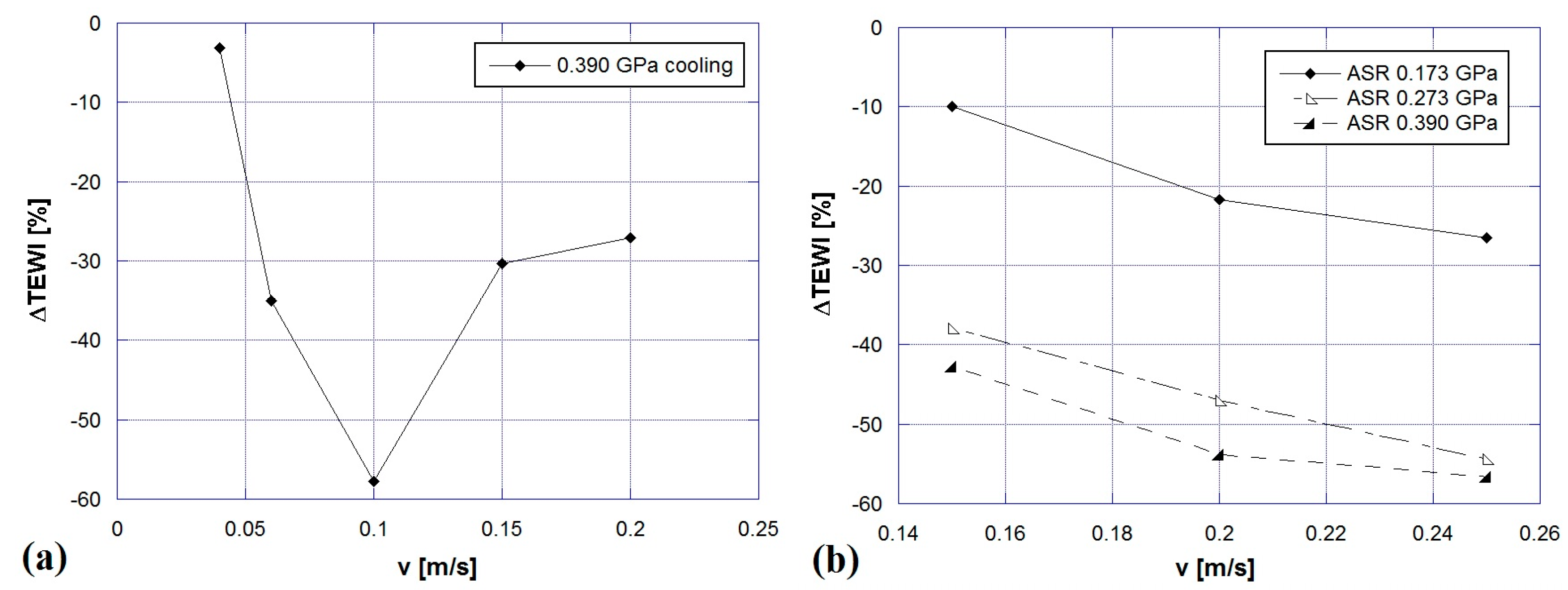
To evaluate the environmental impact, we introduce the relative percentage ∆TEWI index with respect to a VC system working in the same operative conditions and modes, as follows:
TEWI direct contribution of an active caloric heat pump cycle is zero because the refrigerant has solid state and it has zero GWP; whereas direct contribution of the vapor compression plant accounts for about 10% of the whole value. In the cooling mode, we compared the environmental impact of the barocaloric system with the one provided by a domestic vapor compression cooler and we evaluated the energy performances of the latter through an experimental setup of a single evaporator HFC134a domestic refrigerator (with a total volume of 473 L). The description of the test apparatus was reported in [30]. The refrigerant fluid used in the domestic vapor compression refrigerator was HFC134a. The VC heat pump taken as reference in the simulations is a system for domestic usage, mounting scroll compressor and employing HFC134 (GWP = 1430).
Figure 5 exhibits the relative percentage ∆TEWI indexes vs. fluid flow rate for: (a) cooling mode; (b) heat pumping mode, when the system works with base fluids as HTF. From the figures one can observe that a barocaloric system based on ABR cycle provides reduction of the environmental impact with respect to a vapor compression system that touches maximum of −58% and −57%, respectively, in cooling and heat pumping modes.
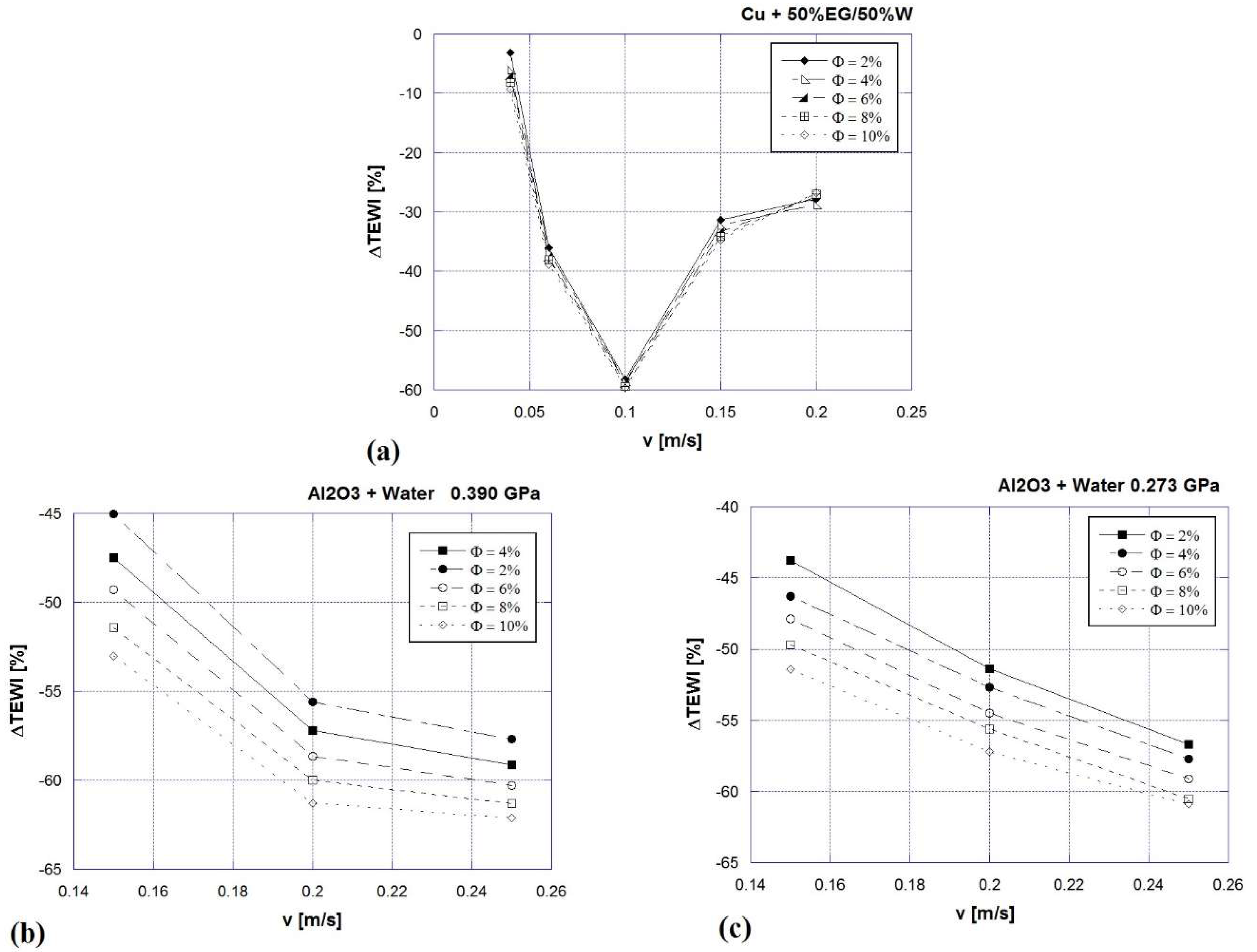
Figure 6 reports the influence that the addition of nanoparticles carries on the TEWI index. Specifically, Figure 6a shows the ∆TEWI percentage vs. fluid flow rate, when the system works in cooling mode employing ASR (0.390 GPa) and Cu + 50%EG/50%W nanofluids as barocaloric refrigerant and HTF respectively. The addition of Cu + 50%EG/50%W nanofluids, in an active barocaloric heat pump working with acetoxy silicone rubber under ∆p = 0.390 GPa, provides a further reduction of environmental impact, touching a maximum of −60% at φ = 10%.
In Figure 6b,c, COP vs. HTF velocity is reported for heat pumping mode where the auxiliary fluid is Al2O3 + water and the solid-state refrigerant (ASR) operates under two different pressure ranges (∆p = 0.273 GPa and ∆p = 0.390 GPa). The addition of Al2O3 + water nanofluids in an active barocaloric heat pump, working with acetoxy silicone rubber under ∆p = 0.390 GPa provides a further reduction of environmental impact that touches a maximum of −62% at φ = 10%.
7. Conclusions
In this paper, the environmental impacts of solid-state barocaloric technology were evaluated through a TEWI analysis carried out through a numerical 2D model of an active barocaloric regenerator. We reported the results of a wide investigation on the environmental impact of barocaloric technology in terms of TEWI index, also making a comparison with two vapor compression-based systems. The analysis focuses on both the cooling and heat pump operation modes, under different operating conditions and auxiliary fluids. The considered barocaloric refrigerant is acetoxy silicone rubber, tested under different pressure fields. Regarding the auxiliary fluids, in a first step we selected water and a 50%ethylene-glycol/50%water mixture, addressed respectively to heat pumping (above 0 °C) and cooling (below 0 °C) operation modes. To enlarge the spectrum of the investigation, we decided to evaluate the environmental impact of barocaloric technology while the system mounts advanced heat transfer fluids: the nanofluids. Specifically, we tested variable concentrations of Al2O3-water nanofluids and of Cu-50%EG/50%W nanofluids, respectively, for heat-pumping and for cooling usage. To evaluate the environmental impact, we introduced the relative percentage ∆TEWI index evaluated with respect to the vapor compression system acting under the same operating conditions and mode. The results revealed that a barocaloric system based on ABR cycle could confer a reduction of the environmental impact with respect to a vapor compression system, touching a maximum of −58% and −57%, respectively in cooling and heat pumping modes, considering the base-fluids as HTF. The addition of nanofluids contributes in reducing the environmental impact up to −62%. Barocaloric technology is not yet mature for vapor compression and there is still a long way to go before it can become fully competitive, but we hope that this study demonstrates that barocaloric refrigeration and heat pumping show strong benefits in terms of environmental impacts.
Author Contributions
Conceptualization, A.G., A.M. and C.M.; methodology, A.G.; software, C.M.; validation, A.G.; formal analysis, A.G. and C.M.; investigation, C.M.; resources, C.A. and A.M.; data curation, A.G., A.M. and C.M.; writing—original draft preparation, C.M.; writing—review and editing, A.G.; visualization, C.A. and A.M.; supervision, C.A., A.G. and A.M.; project administration, C.A. and A.G.; funding acquisition, C.A. and A.G.
Funding
This research received no external funding.
Conflicts of Interest
The authors declare no conflict of interest.
Nomenclature
| Roman symbols | |
| C | specific heat, J kg−1 K−1 |
| CO2 | CO2 contribution to global warming, kgCO2 |
| H | annual operating hours per year, hr yr−1 |
| h | height of the regenerator, m |
| k | thermal conductivity, W m−1 K−1 |
| L | length of the regenerator in fluid flow direction, m |
| P | percent annual refrigerant leak rate, % yr−1 |
| p | pressure, Pa |
| Q | power density associated to barocaloric effect, W m−3 |
| q | number of ABR cycles, - |
| RC | refrigerant charge, kg |
| T | temperature, K |
| TEWI | total equivalent warming impact, kg CO2 |
| t | time, s |
| u | longitudinal fluid velocity, m s−1 |
| v | orthogonal fluid velocity, m s−1 |
| V | lifetime of the system, yr |
| x | longitudinal spatial coordinate, m |
| y | orthogonal spatial coordinate, m |
| Greek symbols | |
| α | CO2 emission from power conversion, kgCO2 kWh yr−1 |
| Δ | finite difference, - |
| δ | infinitesimal difference, - |
| infinitesimal quantity, - | |
| θ | period of the ABR cycle, s |
| μ | dynamic viscosity, Pa s |
| ν | cinematic viscosity, m2 s−1 |
| ρ | density, kg m−3 |
| φ | volume fraction, % |
| τ | period of each step of the ABR cycle, s |
| Subscripts | |
| ad | adiabatic |
| ABR | active barocaloric refrigerator |
| bf | base fluid |
| C | cold heat exchanger |
| cool | cooling |
| D | decompression |
| H | hot heat exchanger |
| hp | heat pump |
| L | regular operation lifetime |
| nf | nanofluid |
| np | nanoparticles |
| p | pump for fluid motion |
| R | refrigerant recycling |
| ref | refrigeration |
| s | solid |
| VC | vapor compression |
References
- Brown, D.R.; Stout, T.B.; Dirks, J.A.; Fernandez, N. The prospects of alternatives to vapor compression technology for space cooling and food refrigeration applications. Energy Eng. 2012, 109, 7–20. [Google Scholar] [CrossRef]
- Goetzler, W.; Zogg, R.; Young, J.; Johnson, C. Alternatives to vapor-compression HVAC technology. Ashrae J. 2014, 56, 12. [Google Scholar]
- Brown, J.S.; Domanski, P.A. Review of alternative cooling technologies. Appl. Eng. 2014, 64, 252–262. [Google Scholar]
- Czernuszewicz, A.; Kaleta, J.; Lewandowski, D. Multicaloric effect: Toward a breakthrough in cooling technology. Energy Convers. Manag. 2018, 178, 335–342. [Google Scholar] [CrossRef]
- Fähler, S.; Rößler, U.K.; Kastner, O.; Eckert, J.; Eggeler, G.; Emmerich, H.; Entel, P.; Müller, S.; Quandt, E.; Albe, K. Caloric effects in ferroic materials: New concepts for cooling. Adv. Eng. Mat. 2012, 14, 10–19. [Google Scholar] [CrossRef]
- Kitanovski, A.; Plaznik, U.; Tomc, U.; Poredoš, A. Present and future caloric refrigeration and heat-pump technologies. Int. J. Refrig. 2015, 57, 288–298. [Google Scholar] [CrossRef]
- Manosa, L.; Planes, A.; Acet, M. Advanced materials for solid-state refrigeration. J. Mater. Chem. A 2013, 1, 4925–4936. [Google Scholar] [CrossRef] [Green Version]
- Ohnishi, T.; Soejima, K.; Yamashita, K.; Wada, H. Magnetocaloric Properties of (MnFeRu) 2 (PSi) as Magnetic Refrigerants near Room Temperature. Magnetochemistry 2017, 3, 6. [Google Scholar] [CrossRef]
- Thang, N.; Dijk, N.; Brück, E. Tuneable giant magnetocaloric effect in (Mn, Fe) 2 (P, Si) materials by Co-B and Ni-B co-doping. Materials 2016, 10, 14. [Google Scholar] [CrossRef]
- Scott, J.F. Electrocaloric materials. Ann. Rev. Mater. Res. 2011, 41, 229–240. [Google Scholar] [CrossRef]
- Sun, X.; Huang, H.; Jafri, H.M.; Wang, J.; Wen, Y.; Dang, Z.M. Wide Electrocaloric Temperature Range Induced by Ferroelectric to Antiferroelectric Phase Transition. Appl. Sci. 2019, 9, 1672. [Google Scholar] [CrossRef]
- Jiang, Z.Y.; Zheng, G.P.; Zheng, X.C.; Wang, H. Exceptionally high negative electro-caloric effects of poly (VDF–co–TrFE) based nanocomposites tuned by the geometries of barium titanate nanofillers. Polymers 2017, 9, 315. [Google Scholar] [CrossRef] [PubMed]
- Wu, Y.; Ertekin, E.; Sehitoglu, H. Elastocaloric cooling capacity of shape memory alloys–role of deformation temperatures, mechanical cycling, stress hysteresis and inhomogeneity of transformation. Acta Mater. 2017, 135, 158–176. [Google Scholar] [CrossRef]
- Strässle, T.; Furrer, A. Cooling by adiabatic (DE) pressurization-the barocaloric effect. Int. J. High Press. Res. 2000, 17, 325–333. [Google Scholar] [CrossRef]
- Chiba, Y. Enhancements of thermal performances of an active magnetic refrigeration device based on nanofluids. Mechanics 2017, 23, 31–38. [Google Scholar] [CrossRef]
- Mugica, I.; Roy, S.; Poncet, S.; Bouchard, J.; Nesreddine, H. Exergy analysis of a parallel-plate active magnetic regenerator with nanofluids. Entropy 2017, 19, 464. [Google Scholar] [CrossRef]
- Aprea, C.; Greco, A.; Maiorino, A.; Masselli, C. Enhancing the Heat Transfer in an Active Barocaloric Cooling System Using Ethylene-Glycol Based Nanofluids as Secondary Medium. Energies 2019, 12, 2902. [Google Scholar] [CrossRef]
- Aprea, C.; Greco, A.; Maiorino, A.; Masselli, C. Electrocaloric refrigeration: An innovative, emerging, eco-friendly refrigeration technique. J. Phys. Conf. Ser. 2017, 796, 012019. [Google Scholar] [CrossRef]
- Aprea, C.; Greco, A.; Maiorino, A.; Masselli, C. The environmental impact of solid-state materials working in an active caloric refrigerator compared to a vapor compression cooler. Int. J. Heat Technol. 2018, 36, 1155–1162. [Google Scholar] [CrossRef]
- Greco, A.; Aprea, C.; Maiorino, A.; Masselli, C. A Review of the state of the art of the solid-state caloric cooling processes at room-temperature before 2019. Int. J. Refrig. 2019, 106, 66–88. [Google Scholar] [CrossRef]
- UNEP. Montreal Protocol on Substances That Deplete the Ozone Layer; United Nation Environment Program (UNEP): New York, NY, USA, 1987. [Google Scholar]
- United Nations. Kyoto Protocol to the United Nation Framework Convention on Climate Change; UN: Kyoto, Japan, 1997. [Google Scholar]
- Heath, E.A. Amendment to the Montreal Protocol on Substances that Deplete the Ozone Layer (Kigali Amendment). Int. Leg. Mater. 2017, 56, 193–205. [Google Scholar] [CrossRef] [Green Version]
- Greco, A.; Mastrullo, R.; Palombo, A. R407C as an alternative to R22 in vapour compression plant: An experimental study. Int. J. Energy Res. 1997, 21, 1087–1098. [Google Scholar] [CrossRef]
- Greco, A.; Vanoli, G.P. Flow boiling heat transfer with HFC mixtures in a smooth horizontal tube. Part II: Assessment of predictive methods. Exp. Fluid Sci. 2005, 29, 199–208. [Google Scholar] [CrossRef]
- Aprea, C.; Greco, A.; Maiorino, A. The substitution of R134a with R744: An exergetic analysis based on experimental data. Int. J. Refrig. 2013, 36, 2148–2159. [Google Scholar] [CrossRef]
- Aprea, C.; Greco, A.; Maiorino, A.; Masselli, C. The drop-in of HFC134a with HFO1234ze in a household refrigerator. Int. J. Therm. Sci. 2018, 127, 117–125. [Google Scholar] [CrossRef]
- Crossley, S.; Mathur, N.D.; Moya, X. New developments in caloric materials for cooling applications. AIP Adv. 2015, 5, 067153. [Google Scholar] [CrossRef]
- Aprea, C.; Greco, A.; Maiorino, A.; Masselli, C.; Metallo, A. HFO1234ze as drop-in replacement for R134a in domestic refrigerators: An environmental impact analysis. Energy Procedia 2016, 101, 964–971. [Google Scholar] [CrossRef]
- Aprea, C.; Greco, A.; Maiorino, A.; Masselli, C.; Metallo, A. HFO1234yf as a drop-in replacement for R134a in domestic refrigerators: A life cycle climate performance analysis. Int. J. Heat Technol. 2016, 34, S212–S218. [Google Scholar] [CrossRef]
- Bell, I.H.; Domanski, P.A.; McLinden, M.O.; Linteris, G.T. The hunt for nonflammable refrigerant blends to replace R-134a. Int. J. Refrig. 2019, 104, 484–495. [Google Scholar] [CrossRef]
- Aprea, C.; Greco, A.; Maiorino, A.; Masselli, C. A comparison between rare earth and transition metals working as magnetic materials in an AMR refrigerator in the room temperature range. Appl. Eng. 2015, 91, 767–777. [Google Scholar] [CrossRef]
- Aprea, C.; Greco, A.; Maiorino, A.; Masselli, C. Energy performances and numerical investigation of solid-state magnetocaloric materials used as refrigerant in an active magnetic regenerator. Therm. Sci. Eng. Prog. 2018, 6, 370–379. [Google Scholar] [CrossRef]
- Aprea, C.; Greco, A.; Maiorino, A.; Masselli, C. A comparison between different materials in an active electrocaloric regenerative cycle with a 2D numerical model. Int. J. Refrig. 2016, 69, 369–382. [Google Scholar] [CrossRef]
- Aprea, C.; Greco, A.; Maiorino, A.; Masselli, C. Solid-state refrigeration: A comparison of the energy performances of caloric materials operating in an active caloric regenerator. Energy 2018, 165, 439–455. [Google Scholar] [CrossRef]
- Aprea, C.; Cardillo, G.; Greco, A.; Maiorino, A.; Masselli, C. A comparison between experimental and 2D numerical results of a packed-bed active magnetic regenerator. Appl. Eng. 2015, 90, 376–383. [Google Scholar] [CrossRef]
- Imamura, W.; Usuda, E.O.; Paixão, L.S.; Bom, N.M.; Gomes, A.M.; Carvalho, A.M.G. Supergiant barocaloric effects in acetoxy silicone rubber around room temperature. arXiv, 2017; arXiv:1710.01761. [Google Scholar]
- ASHRAE. Fundamentals: Si Edition; ASHRAE: Atlanta, GA, USA, 2009. [Google Scholar]
- Mohamad, N.A.; Azis, N.; Jasni, J.; Kadir, A.; Abidin, M.Z.; Yunus, R.; Yaakub, Z. Impact of Fe3O4, CuO and Al2O3 on the AC Breakdown Voltage of Palm Oil and Coconut Oil in the Presence of CTAB. Energies 2019, 12, 1605. [Google Scholar] [CrossRef]
- Irfan, S.A.; Shafie, A.; Yahya, N.; Zainuddin, N. Mathematical Modeling and Simulation of Nanoparticle-Assisted Enhanced Oil Recovery—A Review. Energies 2019, 12, 1575. [Google Scholar] [CrossRef]
- Hussain, M.I.; Kim, J.H.; Kim, J.T. Nanofluid-Powered Dual-Fluid Photovoltaic/Thermal (PV/T) System: Comparative Numerical Study. Energies 2019, 12, 775. [Google Scholar] [CrossRef]
- Fal, J.; Mahian, O.; Żyła, G. Nanofluids in the Service of High Voltage Transformers: Breakdown Properties of Transformer Oils with Nanoparticles, a Review. Energies 2018, 11, 2942. [Google Scholar] [CrossRef]
- Kristiawan, B.; Santoso, B.; Wijayanta, A.; Aziz, M.; Miyazaki, T. Heat transfer enhancement of TiO2/water nanofluid at laminar and turbulent flows: A numerical approach for evaluating the effect of nanoparticle loadings. Energies 2018, 11, 1584. [Google Scholar] [CrossRef]
- Sun, X.H.; Yan, H.; Massoudi, M.; Chen, Z.H.; Wu, W.T. Numerical simulation of nanofluid suspensions in a geothermal heat exchanger. Energies 2018, 11, 919. [Google Scholar] [CrossRef]
- Bellos, E.; Tzivanidis, C. Optimization of a solar-driven trigeneration system with nanofluid-based parabolic trough collectors. Energies 2017, 10, 848. [Google Scholar] [CrossRef]
- Bianco, V.; Vafai, K.; Manca, O.; Nardini, S. Heat Transfer Enhancement with Nanofluids; CRC Press: Boca Raton, FL, USA, 2015. [Google Scholar]
- Hamilton, R.L.; Crosser, O.K. Thermal conductivity of heterogeneous two-component systems. Ind. Eng. Chem. Fund. 1962, 1, 187–191. [Google Scholar] [CrossRef]
- Brinkman, H.C. The viscosity of concentrated suspensions and solutions. J. Chem. Phys. 1952, 20, 571. [Google Scholar] [CrossRef]
Figure 1.
The four steps of active barocaloric regenerative cycle: (A) adiabatically increasing the hydrostatic pressure; (B) cold-to-hot flowing; (C) adiabatically decreasing the hydrostatic pressure; (D) hot-to-cold flowing for (a) cooling; (b) heat pumping operation modes.
Figure 1.
The four steps of active barocaloric regenerative cycle: (A) adiabatically increasing the hydrostatic pressure; (B) cold-to-hot flowing; (C) adiabatically decreasing the hydrostatic pressure; (D) hot-to-cold flowing for (a) cooling; (b) heat pumping operation modes.

Figure 2.
Adiabatic temperature change as a function of the working temperature of acetoxy silicone rubber for decompression (∆p = 0.390 GPa).
Figure 2.
Adiabatic temperature change as a function of the working temperature of acetoxy silicone rubber for decompression (∆p = 0.390 GPa).

Figure 3.
Coefficients of performance detected in: (a) cooling mode and (b) heat pumping mode, when the system works with base fluids as HTF.
Figure 3.
Coefficients of performance detected in: (a) cooling mode and (b) heat pumping mode, when the system works with base fluids as HTF.

Figure 4.
Coefficients of performance detected in: (a) cooling mode ∆p = 0.390 GPa; heat pumping mode (b) ∆p = 0.390 GPa and (c) ∆p = 0.273 GPa when the system employs nanofluids as HTF.
Figure 4.
Coefficients of performance detected in: (a) cooling mode ∆p = 0.390 GPa; heat pumping mode (b) ∆p = 0.390 GPa and (c) ∆p = 0.273 GPa when the system employs nanofluids as HTF.

Figure 5.
∆TEWI percentage vs. fluid flow rate for: (a) cooling mode; (b) heat pumping mode, when the system works with base fluids as HTF.
Figure 5.
∆TEWI percentage vs. fluid flow rate for: (a) cooling mode; (b) heat pumping mode, when the system works with base fluids as HTF.

Figure 6.
∆TEWI percentage vs. fluid flow rate for: (a) cooling mode ∆p = 0.390 GPa; heat pumping mode (b) ∆p = 0.390 GPa and (c) ∆p = 0.273 GPa when the system employs nanofluids as HTF.
Figure 6.
∆TEWI percentage vs. fluid flow rate for: (a) cooling mode ∆p = 0.390 GPa; heat pumping mode (b) ∆p = 0.390 GPa and (c) ∆p = 0.273 GPa when the system employs nanofluids as HTF.


Table 1.
Thermal and physic features of acetoxy silicone rubber.
| Material | Tpeak [K] | Δp [GPa] | ∆Tad,max [K] | Density [kg/m3] | Thermal Conductivity [W/mK] |
|---|---|---|---|---|---|
| ASR | 298 | 0.390 | 41.1 | 960 | 1.48 |
Table 2.
Thermophysical characteristics of Al2O3 and Cu nanoparticles.
| Material | Specific Heat [J/kgK] | Density [kg/m3] | Thermal Conductivity [W/mK] |
|---|---|---|---|
| Al2O3 | 765 | 3970 | 36 |
| Cu | 383 | 8933 | 401 |
© 2019 by the authors. Licensee MDPI, Basel, Switzerland. This article is an open access article distributed under the terms and conditions of the Creative Commons Attribution (CC BY) license (http://creativecommons.org/licenses/by/4.0/).
Share and Cite
MDPI and ACS Style
Aprea, C.; Greco, A.; Maiorino, A.; Masselli, C. Is Barocaloric an Eco-Friendly Technology? A TEWI Comparison with Vapor Compression under Different Operation Modes. Climate 2019, 7, 115. https://0-doi-org.brum.beds.ac.uk/10.3390/cli7090115
AMA Style
Aprea C, Greco A, Maiorino A, Masselli C. Is Barocaloric an Eco-Friendly Technology? A TEWI Comparison with Vapor Compression under Different Operation Modes. Climate. 2019; 7(9):115. https://0-doi-org.brum.beds.ac.uk/10.3390/cli7090115
Chicago/Turabian StyleAprea, Ciro, Adriana Greco, Angelo Maiorino, and Claudia Masselli. 2019. "Is Barocaloric an Eco-Friendly Technology? A TEWI Comparison with Vapor Compression under Different Operation Modes" Climate 7, no. 9: 115. https://0-doi-org.brum.beds.ac.uk/10.3390/cli7090115
Note that from the first issue of 2016, this journal uses article numbers instead of page numbers. See further details here.