Advanced Materials and Technologies for Compressor Blades of Small Turbofan Engines †


1
Mechanical Engineering Department, National University “Zaporizhzhia Polytechnic”, 64 Zhukovskogo st, 69063 Zaporizhzhia, Ukraine
2
Motor Sich JSC, 15 Motorostroiteley Ave., 69068 Zaporizhzhia, Ukraine
3
Instytut Techniczny Wojsk Lotniczych, ul. Księcia Bolesława 6, 01-494 Warsaw, Poland
*
Author to whom correspondence should be addressed.
†
This paper is an extended version of our paper published in 10th EASN International Conference on Innovation in Aviation & Space to the Satisfaction of the European Citizens.
Aerospace 2021, 8(1), 1; https://0-doi-org.brum.beds.ac.uk/10.3390/aerospace8010001
Submission received: 5 November 2020
/
Revised: 13 December 2020
/
Accepted: 16 December 2020
/
Published: 22 December 2020
(This article belongs to the Special Issue 10th EASN International Conference on Innovation in Aviation & Space to the Satisfaction of the European Citizens)
Abstract
:Manufacturing costs, along with operational performance, are among the major factors determining the selection of the propulsion system for unmanned aerial vehicles (UAVs), especially for aerial targets and cruise missiles. In this paper, the design requirements and operating parameters of small turbofan engines for single-use and reusable UAVs are analysed to introduce alternative materials and technologies for manufacturing their compressor blades, such as sintered titanium, a new generation of aluminium alloys and titanium aluminides. To assess the influence of severe plastic deformation (SPD) on the hardening efficiency of the proposed materials, the alloys with the coarse-grained and submicrocrystalline structure were studied. Changes in the physical and mechanical properties of materials were taken into account. The thermodynamic analysis of the compressor was performed in a finite element analysis system (ANSYS) to determine the impact of gas pressure and temperature on the aerodynamic surfaces of compressor blades of all stages. Based on thermal and structural analysis, the stress and temperature maps on compressor blades and vanes were obtained, taking into account the physical and mechanical properties of advanced materials and technologies of their processing. The safety factors of the components were established based on the assessment of their stress-strength characteristics. Thanks to nomograms, the possibility of using the new materials in five compressor stages was confirmed in view of the permissible operating temperature and safety factor. The proposed alternative materials for compressor blades and vanes meet the design requirements of the turbofan at lower manufacturing costs.
1. Introduction
Currently, one of the most promising areas in the aerospace and defence industry is the development of unmanned aerial systems for various purposes. They are based on unmanned aerial vehicles (UAVs) of both reusable and single use. Ukrainian [1] and global manufacturers offer gas-turbine engines for UAVs of various types [2,3]. While full-scale turboprops and turbofans, as a rule, are based on engines designed for manned aircraft [4], small turbofans are custom-made [5,6]. They typically have a compact and simplified single-shaft structure, determined by the tactical and technical characteristics of the platform [7].
Small turbofan engines (Table 1) are designed for target drones (Streaker, Lakshya) and cruise missiles such as R-360 Neptune, Kite, Kh-55, Tomahawk and Harpoon. Their main performance characteristics include a short life cycle (if used as weapons), small size and weight and, as a result, high thrust-to-weight ratio. Also, operation on an unmanned platform contributes to the fact that they are not subject to the aviation safety regulations. Such engines are produced by JSC Motor Sich, SE Ivchenko Progress and a number of foreign firms. Engines of this class have thrust in the range of 1.9–4 kN, a low bypass ratio and a small dry mass not exceeding 60–85 kg. At the same time, to ensure high efficiency, such turbofan engines rotate at several tens of thousands of revolutions per minute, which imposes special requirements on the design of their components and selection of materials. First of all, they should exhibit high specific strength under static loads and a relatively low manufacturing cost. At the same time, their durability, due to the short life cycle and lack of pilot, is not of prime importance.
In small turbofan engines both radial and axial compressors are used. Currently, various types of titanium alloys are successfully used for manufacturing the blades and vanes of axial compressors [9,10]. The most common are VT6 (Ti-6Al-4V), VT3-1 (Ti-6.7Al-2.5Mo-l.8Cr-0.5Fe-0.25Si) and VT8 (Ti-6.8Al-3.5Mo-0.32Si). For compressor stages with increased air temperature along the gas path, heat-resistant titanium alloys of the VT25 (Ti-6.8Al-2.0Mo-2.0Zr-2.0Sn-l.0W-0.3Si) type are used [11,12]. For the last stages of the compressor, taking into account the temperature level, heat-resistant nickel-based alloys such as Inconel 718 (EP718-ID) and similar are used. A common drawback of these materials, along with the high cost and energy costs of production, is their poor machinability. Having a combination of the properties necessary for the compressor blades of a manned aircraft’s engine, they are redundant when used on UAVs. This leads to the increased cost of engines and UAVs in general. To meet the requirements for UAV power plants, it is necessary to introduce new materials and technologies, which reduce their manufacturing cost.
There are several modern technologies which can be used for manufacturing gas turbines for UAVs [13]. With regard to compressor blades, a number of candidate materials is considered, for example, sintered powder alloys; rare earth aluminium alloys; alloys based on titanium aluminides and others [14,15].
At present, only surfaces of compressor blades are hardened [16], primarily by laser shock peening [17]. However, surface hardening does not modify the inner structure of the alloy. Therefore, to significantly increase the strength and ductility of aircraft materials, severe plastic deformation (SPD) technologies are used [18,19] but the size of produced ingots is still limited. What is more, for each compressor stage, there are limitations both in the operating temperature and mechanical properties which have to be met by the introduced materials.
In this work, to reduce the manufacturing cost of a selected small turbofan engine, alternative materials and technologies for producing compressor aerofoils are introduced and evaluated. To ensure structural integrity, the static safety factor is assessed for the blades and vanes of individual stages, taking into account their operating temperature. The key objectives of this work include material selection, strength testing, airflow simulation of the compressor to obtain pressure fields on aerofoil surfaces of all stages as well as gas temperature and finally the structural analysis of components which evaluates their stress and static safety factor.
2. Materials and Methods
2.1. Twist Extrusion
Various SPD methods [20,21] are introduced to improve mechanical, physical, and functional properties of metals and alloys by forming their submicrocrystalline structure [22,23]. Twist extrusion (TE) is a variant of the simple shear deformation process that was introduced by Beygelzimer [24]. Under TE processing, a prismatic billet is extruded through a twist die.
In this work, a number of standard and powder metal alloys (Table 2) sourced from various contractors were processed with TE. The titanium billets were made from annealed VT8 rods of increased quality, 32 mm in diameter (GOST 26492-85), produced by VSMPO-AVISMA Corporation. Sintered titanium was synthesised in laboratory by pressing and subsequent vacuum sintering of powder mixtures based on PT5 titanium powder (TU U14-10-026-98) produced by the Zaporizhzhia Titanium-Magnesium Plant. The grain size was 160–500 [25].
The billet (Figure 1) was 70 mm long with the cross-section of 18 × 28 mm. It was placed in a matrix with a helical channel of rectangular cross section with an angle of the helix inclination to the TE axis. The extrusion pressure was = 1600 MPa for all the studied alloys. To increase their plasticity, back pressure = 200 MPa was applied to the front end of the billet. To transmit back pressure, a deformable medium was used, which was either a mixture based on the low-melting glass or a copper billet [41].
There are different approaches to modelling and optimising the TE process [42,43], usually based on FE methods. Calculations and experiments are aimed to obtain high plastic strain and uniform ultrafine grains [21]. In this work the Beygelzimer’s approach [41,44] is followed. The total relative shear deformation per pass was calculated as follows [41]:
where is the maximum inclination angle between the twist line and the extrusion axis. As the deflection angle of the helical channel was 45° for all investigated materials, the total shear deformation per pass was approximately 1.15. Five TE passes were carried out, so the total relative shear deformation of the billet was 5.77.
The porosity of the specimens was measured by the hydrostatic weighing method (GOST 18847-84) and by analysing the micrographs of metallographic specimens (GOST 9391-80) [45]. In the first case, the specimens were submerged into distilled water, whose temperature was measured by a mercury thermometer. There was no porosity in specimens made of VT8 titanium alloy. After TE, a slight (within a few percent) increase in porosity was observed, which could be associated with an increase in the number of crystal lattice defects.
For the investigation of structure and the fractographic analysis of fracture surfaces, a NEOPHOT light microscope and a JEOL scanning electron microscope was used [46]. The average grain size in the samples after five TE passes was in the range of 200–500 nm for titanium alloys [45]. The grain size in the original material was 150–300 .
2.2. Sintered Titanium
One of the well-known methods of reducing the manufacturing cost of the axial compressor is using sintered titanium alloys [47,48] but their residual porosity and low ductility are the reasons for which up to now they are used in aircraft engines for a narrow circle of lightly loaded, non-critical components. Therefore, powder materials need consolidation and grain refinement, which can be effectively achieved by the SPD process of high-pressure torsion (HPT) [49,50]. However, HPT can produce only very small samples which cannot be used for manufacturing compressor blades. Therefore, our recent paper [51] uses the physical similarity of the processes occurring in a thin layer of material during HPT and TE to simulate twist extrusion with the available HPT data.
In this work, among others, alloys synthesised from a mixture of selected powder components [25,52] were evaluated. Doped elements (pure Al, Mo and Si metals) were mixed with the matrix titanium powder in a mixer drum at 60–80 rpm to ensure the required chemical composition of the test alloy after sintering. The powders were subjected to single-action compaction in rigid dies at room temperature. The compaction force was 730–760 MPa. The compacts were sintered in vacuum in the range of 1250–1270 °C with an isothermal holding time of 2.5–3 h and cooled down in the furnace in vacuum.
Our previous paper [46] showed that the characteristics of sintered titanium alloys subjected to SPD in some indicators exceed similar values for regular alloys in cast and deformed states. The preliminary structural analysis of blades made of sintered titanium with subsequent SPD confirmed that their safety margin meets the operating conditions [53]. However, an important factor that limits the use of alloys in the compressor design is the elevated temperature caused by air compression in the gas path. Also, given the high rotational speed of the engine, close to 40–50 thousand revolutions per minute, stress analysis results depend heavily on the calculated pressure field. As the information on the operating temperature and pressure in the compressor stages of small turbofan engines is very limited [54,55], air flow and thermal analysis is performed in this work.
2.3. Aluminium-Based Alloys
Aluminium alloys with lithium and scandium are well suited to be used in turbofan engines, given their high specific strength which exceeds those of titanium alloys [35,36,37]. SPD effectively hardens the cast structure of aluminium, so it could be used instead of homogenization annealing [40,56]. However, it is necessary to take into account the operating temperature of components since the heat resistance of aluminium alloys is significantly lower than that of titanium and nickel ones.
Intermetallic Fe3Al-based alloys could potentially substitute more expensive superalloys and creep-resistant steels. They are characterized by a combination of interesting functional characteristics such as excellent resistance to oxidation, sulfidation and carburizing, good resistance to seawater corrosion, wear, erosion, or cavitation, and high strength to weight ratio [57,58].
In this work, a variant of the standard aerospace aluminium alloy 7055+Sc was used (Al-Zn-Mg-Cu-Sc). It was obtained in laboratory by melting with the additive of scandium. Its initial porosity was 3–4% and it reduced to less than 1.5% after TE.
Lightweight, heat-resistant and weldable alloys based on titanium aluminides [34] make it possible to design more efficient compressors. These materials offer a number of unique properties—low density, relatively high melting point, high modulus of elasticity, resistance to oxidation and fire, high specific heat resistance, and so forth. They are well suited for the last stages of compressor blades but their effectiveness is controversial. On one hand, due to the combination of specific strength and heat resistance, they can replace traditional nickel-based alloys [33,59]. On the other hand, the technology of their manufacturing and processing is quite energy-intensive, which makes them cost-ineffective in the case of small turbofan engines. While heat explosion is a significantly cheaper technology to synthesise such materials [60], their mechanical properties are not satisfactory for aircraft components, in particular for aero-engines.
In this case, a promising, cost-saving technology for the preparation of semi-finished intermetallic -TiAl alloys for aircraft, in particular compressor blades, was self-propagating high-temperature synthesis and subsequent TE of the initial ingots [32]. The initial porosity of the -TiAl alloy was 35–40% and it decreased to 4–5% after TE.
Taking into account that this technology not only reduces the cost of manufacturing compressor blades, but also increases the level of their mechanical characteristics, assessing the possibility of their use in the design of engines for UAVs is important.
2.4. Strength Testing
To determine the mechanical properties of alloys, 11 mm × 11 mm × 56 mm billets were used to produce standard tensile samples in accordance with GOST 1497-84. Strength testing was carried out on the INSTRON 8802 servohydraulic machine under programmed loading at room and elevated temperature. Five reference samples, mass-produced from VT8 alloy bars, were measured to validate the test procedure. The extensometer span was 25 mm. The specimen test portion strain was controlled with an accuracy of 1 µm. The accuracy of stress measurements in the specimen cross-section was ±3 MPa. Extensometer and spring dynamometer readings were ADC-processed and sampled with a rate of = 0.01 s [25,61]. The actual tensile testing covered more than three specimens for each case.
Table 3 presents the physical and mechanical properties of considered blade materials. The last column shows that materials subjected to TE become less heat-resistant because intensive grain grow begins at a lower temperature. The ratio of Young’s modulus and material ultimate strength to density characterises the specific stiffness and specific strength of the material. From the point of view of strength, for the production of aircraft engine components, the most promising materials are those with the maximum values of the specified characteristics. This makes it possible to ensure not only a high level of their strength reliability (safety factor), but also a decrease in the mass. It is known that reducing the rotor mass is one of the best ways for improving the design of a gas turbine, since it effectively reduces the level of dynamic loads and vibration [62].
Taking into account that the analysed technologies for obtaining ingots for compressor components (powder metallurgy and severe plastic deformation) lead to a change in the indicated characteristics of materials at the level of 10%, they were not considered as a criterion for choosing a production technology. At the same time, when choosing a material, preference was given to that material, the specific stiffness and strength of which is higher while ensuring equal safety margins.
2.5. Modelling the Compressor
The effectiveness of the use of candidate materials for manufacturing blades and vanes was evaluated for an axial compressor with the geometry representative of small turbofan engines. The stress-strain state of compressor components was estimated by a coupled Finite Element (FE) Analysis which included a flow calculation and stress analysis. The obtained pressure and temperature fields were applied directly to aerofoil surfaces to determine the stresses and strains in components [63,64,65]. The analysis was performed for a 6-stage axial compressor (Figure 2). The fan is not considered in this paper as its blades are too large for SPD technology and also sintered alloys do not provide the necessary level of strength.
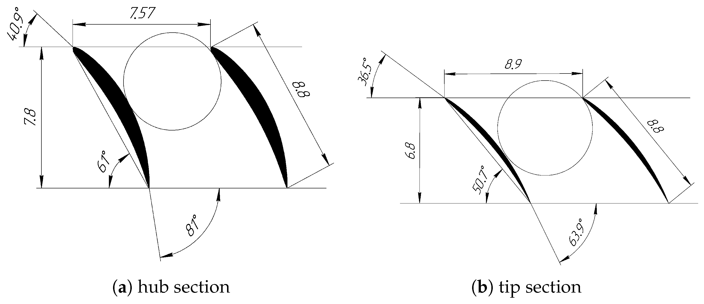
The profile section of the first compressor stage is shown in Figure 3. The geometry of the compressor blades corresponds to the standard aerodynamic profile of NACA 7404- 7405 AIRFOIL. The total number of blades in the compressor stages is given in Table 4.
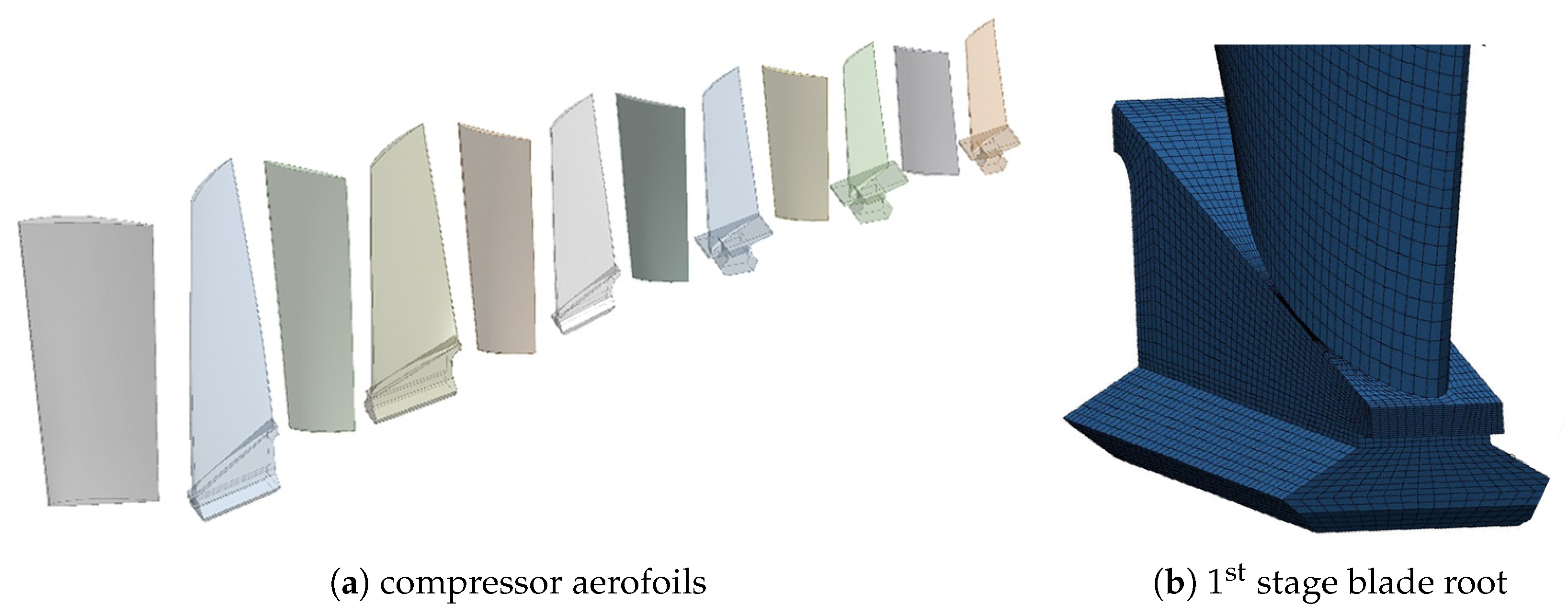
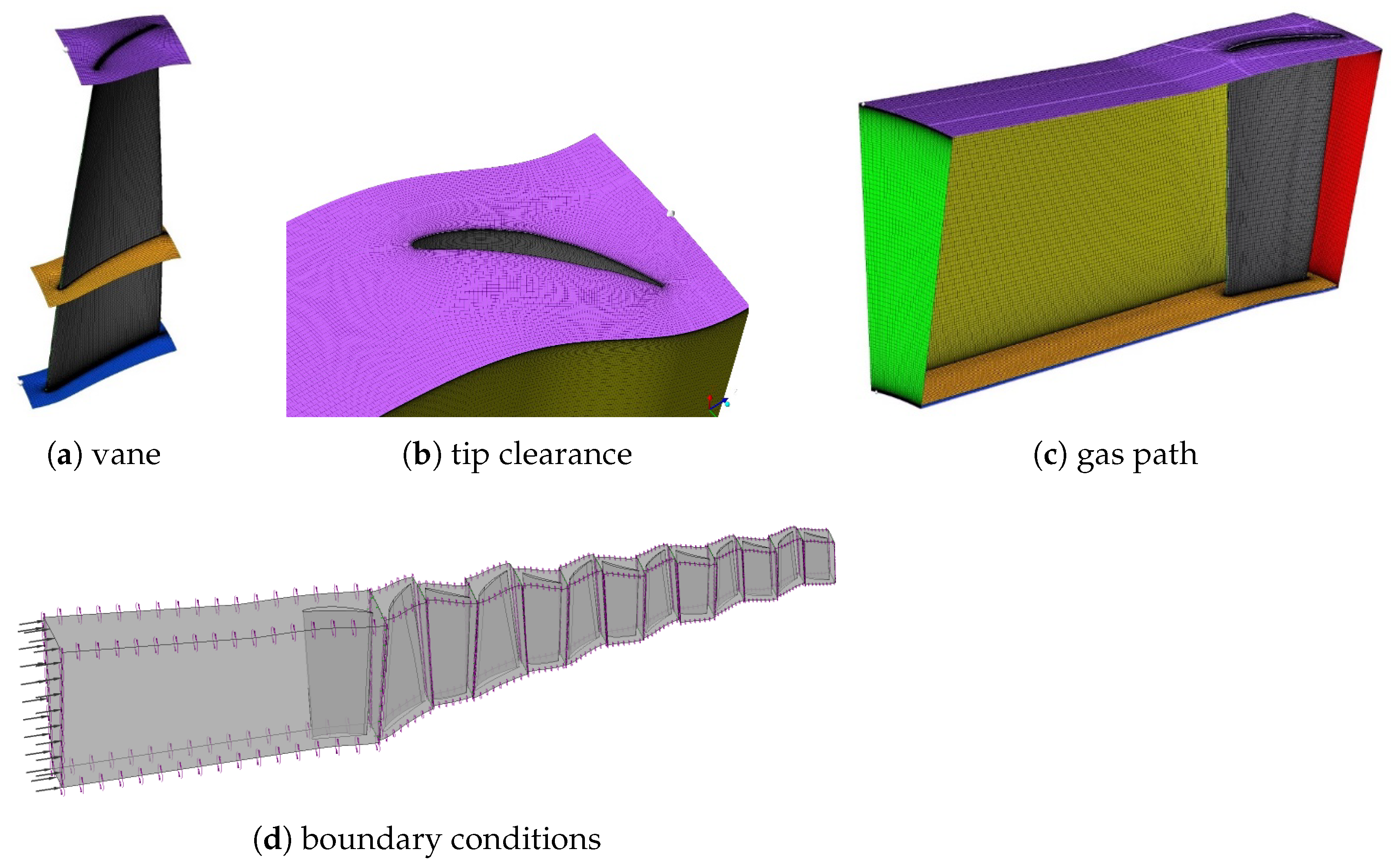
Using the Unigraphics NX system, models of blades and vanes (one pair per each stage) were built. To develop the aerofoil profile, the surface modelling method was used, while for roots, the method based on Boolean operations with geometric primitives (Figure 4). To create finite element models, an ICEM CFD grid generator was used. The mesh models of the blades consisted of 15,000–18,000 hexagonal SOLID 186 elements. ANSYS Workbench version 2019 R3 was used for the calculations. Blades were fixed at the root plane.
2.6. CFD Model
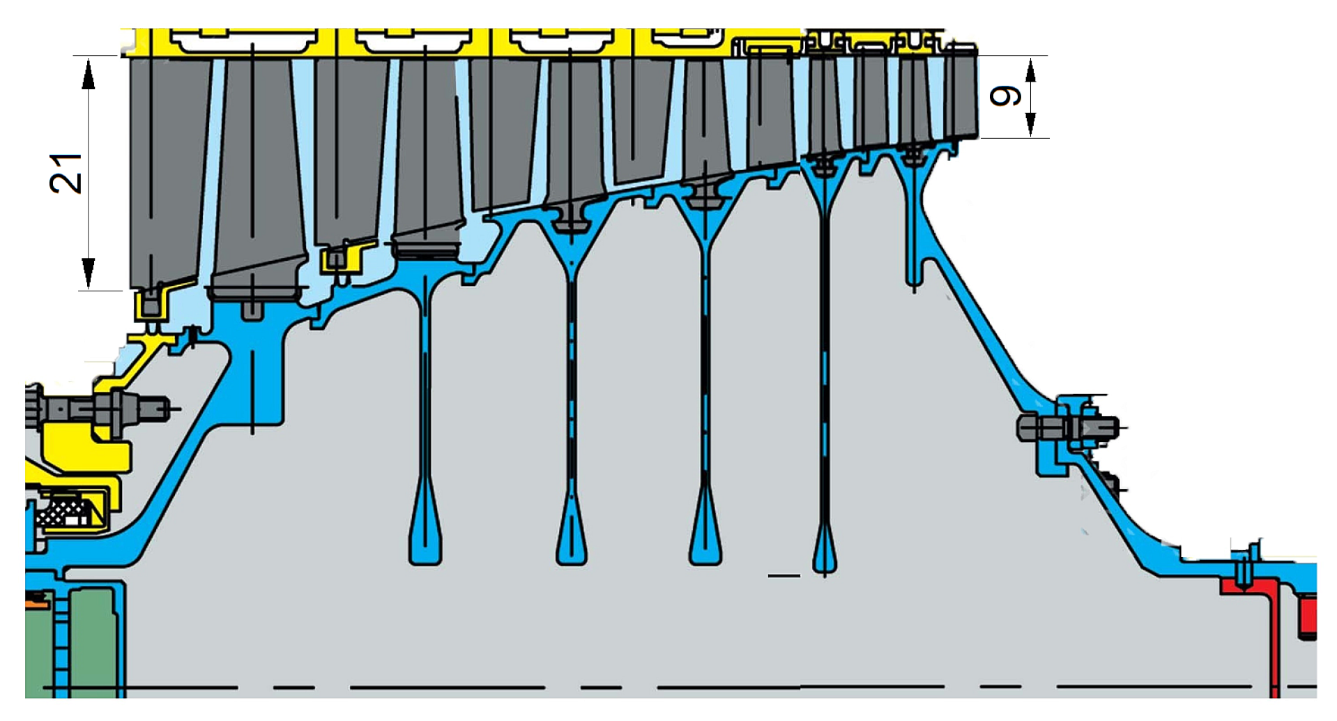
Temperature along the compressor gas path and pressure on the aerodynamic surfaces of the blades was determined by flow calculation in Ansys CFX with the finite element method. The CFD model of the compressor inter-blade channel was obtained by arranging the domains of each compressor stage in the axial and radial directions. To build a mesh of the compressor flow, the TurboGrid grid generator was used (Figure 5). Volumetric finite elements intended for CFD calculations were used. To reduce the required computing power, one blade was modelled for each compressor stage with the cyclic symmetry along the boundaries of the domain (Figure 5c). The boundary conditions were set in the form of total inlet pressure, mass flow at the compressor outlet, and rotational speed (Figure 5d).
An interface between stationary and rotating regions (Stage Mizing-Plane) was defined on the mating boundaries of regions belonging to different steps, which allows for the interpolation between mating grids. A satisfactory criterion for the convergence of the calculation was the value of the mean square residual at the level of . This convergence was achieved at 1200–1400 iterations. We used the SST (Menter’s Shear Stress Transport) model of turbulence [66,67], as the most accurate and reliable for flows with a positive pressure gradient when flowing around profiles. At the inlet and outlet of the compressor, the mass flow rate and temperature corresponding to the engine emergency operation were set. The the simulation results were validated according to the methodology described in Reference [68].
2.7. Thermal Structural Analysis
To assess the stress-strain state of the components and temperature distribution, the results of the flow calculation were used. The aerodynamic surfaces of the blades (pressure and suction sides) were loaded with the pressure and temperature fields obtained as a result of preliminary flow calculation.
Typically, both static and fatigue strength are evaluated for new components [69,70] which requires reliable material data to check the safety factor. It includes the endurance limit of laboratory samples at operating temperature, the amplitude of alternating stress at the time of failure, as well as the effective coefficient of stress concentration and the magnitude of their variation. Considering that when analysing the suitability of new materials, these data were not available, the static safety factor () was evaluated with the following formula [71]:
where —conditional yield strength of the blade material, —maximum value of the von Mises stress in the compressor blades.
3. Results and Discussion
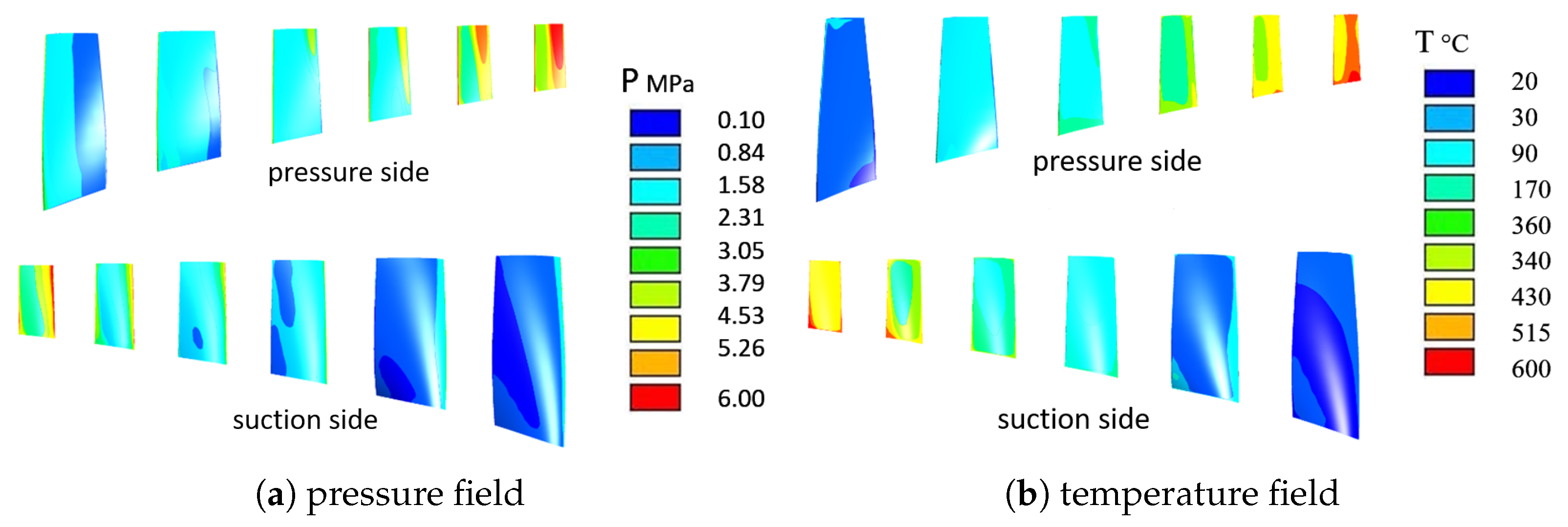
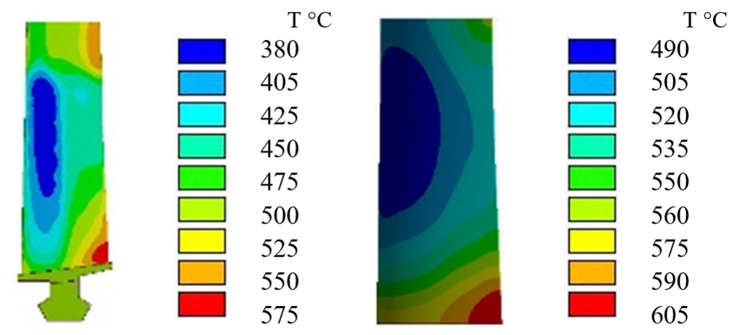
Figure 6 shows the calculated pressure fields on blade surfaces, and the flow temperature. The flow temperature was used as the initial data for thermal analysis as the boundary condition of the third kind to calculate the surface temperature of the blades (Figure 7). The obtained operating temperature of the compressor blades makes it possible to evaluate the suitability of the considered materials. Given that the blade has a relatively small profile thickness, the temperature distribution over the cross-section was considered uniform.
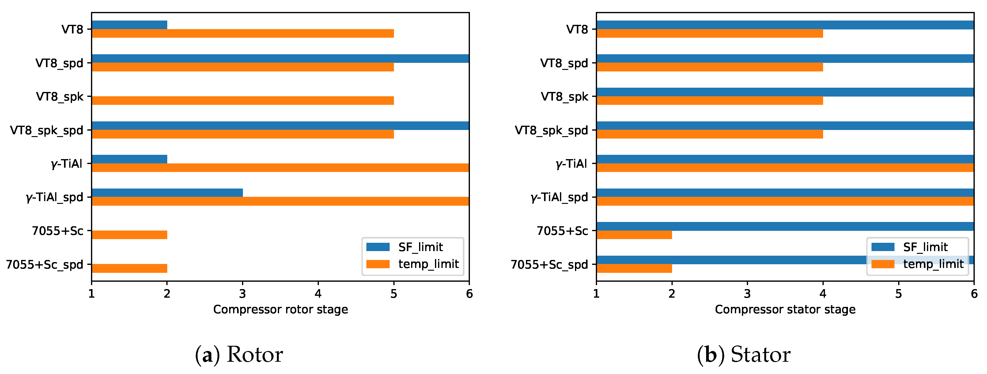
The calculated stress distribution in the aerofoils (Figure 8) made it possible to evaluate candidate materials and processing technologies in view of their structural integrity. Values of maximum equivalent stress and static safety factor of blades and vanes made from advanced materials and technologies are given in Table 5 and Table 6. Materials with safety factor less than the threshold of 1.1 cannot be used in the particular stage [72]. This value was selected by the manufacturer on the basis of industrial experience and reliability data. Under certain conditions, such a low SF threshold is acceptable in aircraft components, especially for unmanned and single-use platforms.
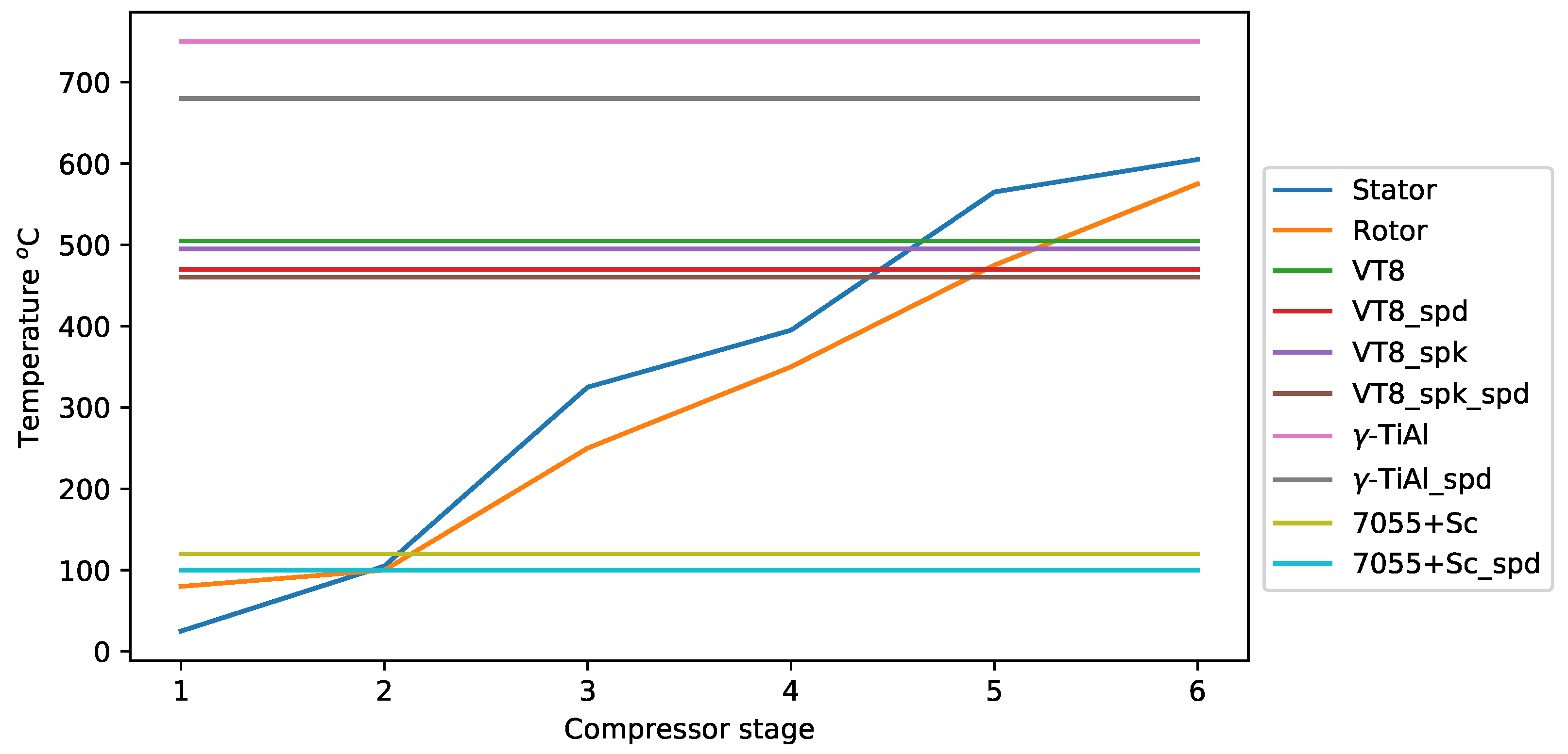
Analysing the obtained data, we can conclude that the candidate materials and processing technologies can be used for manufacturing compressor components. Considering that material selection by the temperature and strength criteria is complicated due to the variety of limiting factors, nomograms were developed for this purpose (Figure 9 and Figure 10). It can be noted that VT8 alloy is limited to rotor stages 1–2 in terms of its strength reliability. The use of SPD methods expands the scope of its application up to the 7th stage; however, in terms of the temperature limit, VT8 usage is limited to blades of the first five stages.
It can be inferred that the strength of the blades of all compressor stages made of sintered titanium, is below the acceptable threshold (SF = 1.1). Therefore, they cannot be used, despite the significantly lower manufacturing cost in comparison with an alloy in a deformed state. However, the use of SPD methods, due to the elimination of porosity, the formation of a submicrocrystalline structure in the entire cross-section and the homogenization of alloying elements, contributes to a significant increase in strength and, as a consequence, the expansion of their application to all stages.
At the same time, the operating temperature of the submicrocrystalline alloy is lower than one with the standard structure which does not allow for their use in 6th stage blades (Figure 9). Considering that the compressor vanes experience a load only from the flow, the field of application of the VT8 alloy is limited only by its operating temperature, regardless of the technology of production and processing. Despite the great strength, the sintered titanium processed with TE, in comparison with the regular sintered alloy, has the operating temperature lower by 40 °C, which may limit its use. Taking into account the lower cost of obtaining sintered titanium alloys, their use is the most rational in the blades of the first five stages.
Aluminium alloys with a coarse-grained and submicrocrystalline structure according to the thermal criterion can be applied only to blades of the first and second stages. However, a safety factor assessment indicates that their application is limited to stator vanes. At the same time, modern aluminium alloys can be used to make vanes without SPD processing, which reduces the manufacturing cost. Given the low weight and cost of aluminium vanes compared to titanium ones, the replacement of the material is justified. Moreover, the well-known problems of aluminium alloys, such as low hardness and resistance to sand erosion, are an uncritical factor for UAV engines.
Alloys based on titanium aluminides are the most heat resistant of the considered ones, which predetermines their use for manufacturing blades of the last compressor stages. From the point of view of the permissible operating temperature, this alloy can be applied to blades of all stages regardless of their structural state (Table 3). At the same time, from the point of view of strength reliability for blades, their use is allowed up to stage 2 without additional strain hardening and up to 3rd stage with TE processing (Table 5).
For all stator stages, the safety factor of vanes made from titanium aluminides is higher than the threshold (Table 6). Thus, this alloy can be used for manufacturing vanes of stages 5 and 6, for which, due to temperature limitations, lighter titanium alloys may not be applicable. Nevertheless, the replacement of more heat-resistant Inconel 718 alloys with titanium aluminides would reduce the weight of gas turbine engines.
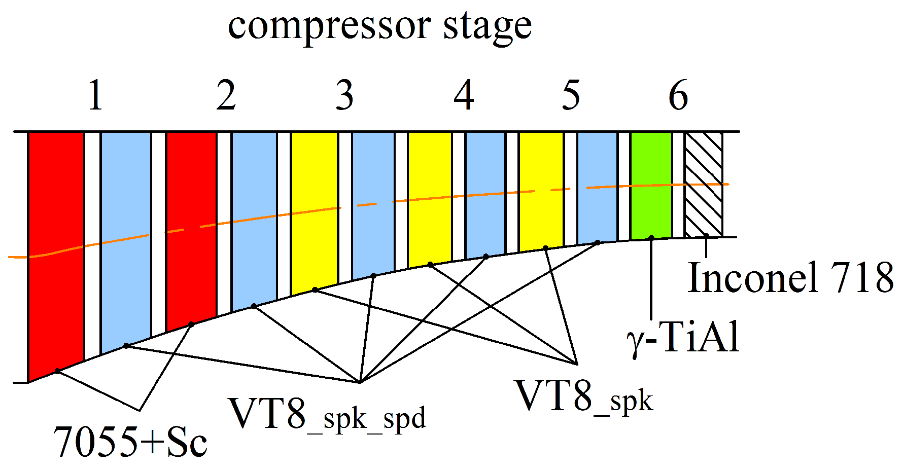
It should be noted that the considered temperature limitations of submicrocrystalline alloys are associated with the onset of recrystallization processes. Considering that this processes take a relatively long time, exceeding the mission time of single-use UAVs (cruise missiles, disposable reconnaissance vehicles, aerial targets, etc.), this restriction can be removed for such turbofan engines. In this case, their maximum allowable temperature will be similar to alloys in a coarse-crystalline state. The calculated values of the safety factors for compressor components made from considered alloys and technologies let us propose their field of application (Figure 11).
4. Conclusions
The analysis of the thermal and stress-strain state of the compressor blades and vanes, in combination with the tensile testing of the candidate alloys, made it possible to develop recommendations for their use:
- (1)
- It was found that the vanes of the first fifth stator stages can be made of sintered VT8 titanium alloy without strain hardening. Respectively, the blades of the first fifth rotor stages can be made of sintered VT8 titanium alloy, subjected to SPD processing.
- (2)
- 7055+Sc aluminium alloy, regardless of the use of TE, can be used to make vanes of the first two stages.
- (3)
- Titanium aluminides (-TiAl) processed with TE can be used for the blades of stages 1–3 and all stator stages. Considering the lower cost of sintered titanium compared to -TiAl alloy, it is reasonable to use it only for the 6th-stage vanes.
- (4)
- None of the candidate materials are suitable for making 6th-stage blades, so a superalloy such as Inconel 718 has to be used instead.
The thermal and structural analysis of this high-speed axial compressor shows that its blades are extremely loaded up to the strength and temperature limits of the available alloys. Taking into account that the change in the physical and mechanical properties of materials can affect not only the stress-strain state of the blades but also their dynamic characteristics, the natural frequencies of blades need to be evaluated in the next stage of research. For the compressor under study, Campbell diagrams and the surge margin will be calculated. Also, the damping properties of alloys in various conditions should be analysed.
Author Contributions
D.P. and Y.D. conceived and designed the research; D.P synthesised and processed the alloys; Y.D. and D.P developed FEM and CFD models and performed structural analysis; D.P. and R.P. verified and evaluated the results. D.P., Y.D. and R.P. drew conclusions and produced the paper. All authors have read and agreed to the published version of the manuscript.
Funding
This research received no external funding.
Acknowledgments
We would like to thank Wieslaw Beres and Sylwester Klysz for their comments on an earlier version of the manuscript, although any errors are our own and should not tarnish the reputations of these esteemed persons.
Conflicts of Interest
The authors declare no conflict of interest. Motor Sich JSC had no role in the design, execution, interpretation, or writing the study. The views, information, or opinions expressed herein are solely those of the authors and do not necessarily represent the position of any organization.
Abbreviations
The following abbreviations and symbols are used in this manuscript:
| Poisson’s ratio | |
| density | |
| conditional yield strength | |
| von Mises stress | |
| back pressure | |
| E | Young’s modulus |
| forward pressure | |
| p | pressure |
| safety factor | |
| T | temperature |
| CFD | computational fluid dynamics |
| FE | finite element |
| HPT | high-pressure torsion |
| IGV | inlet guide vanes |
| JSC | join-stock company |
| rpm | revolutions per minute |
| SE | state enterprise |
| SPD | severe plastic deformation |
| SPK | sintered metal powder |
| SST | Menter’s Shear Stress Transport model of turbulence |
| TE | twist extrusion |
| UAV | unmanned aerial vehicle |
| UTS | ultimate tensile strength |
| VT8 | Titanium wrought alloy |
References
- Telesyk. Motor Sich Engines for UAVs (Dvigateli “Motor Sich” Dlja BPLA). Available online: https://telesyk.livejournal.com/146218.html (accessed on 2 November 2020).
- Brooks, V.E. Small Turbine Engine Evolution. SAE Int. J. Aerosp. 2008, 1, 2008-01-2874. [Google Scholar] [CrossRef]
- Costa, F.P.; Henrique, L.; Whitacker, L.; Bringhenti, C.; Tomita, J.T. An Overview of Small Gas Turbine Engines. In Proceedings of the 24th ISABE conference, Canberra, Australia, 22–27 September 2019. ISABE 2019, ISABE-2019-24387. [Google Scholar]
- Weinberg, M.; Wyzykowski, J. Development and Testing of a Commercial Turbofan Engine for High Altitude UAV Applications. SAE Tech. Pap. 2001. Available online: https://0-saemobilus-sae-org.brum.beds.ac.uk/content/2001-01-2972/ (accessed on 8 May 2020). [CrossRef]
- Rodgers, C. Affordable Smaller Turbofans. Volume 1: Turbo Expo 2005. ASMEDC 2005, 1, 1–10. [Google Scholar] [CrossRef]
- Large, J.; Pesyridis, A. Investigation of micro gas turbine systems for high speed long loiter tactical unmanned air systems. Aerospace 2019, 6, 55. [Google Scholar] [CrossRef] [Green Version]
- Nelson, J.R.; Dix, D.M. Development of Engines for Unmanned Air Vehicles: Some Factors to Be Considered; Technical Report; Institute for Defense Analyses: Alexandria, VA, USA, 2003. [Google Scholar] [CrossRef]
- Razinsky, E.; Cae, T. The J402-CA-702-A Modern 1000 Lb. Thrust RPV Engine. In Proceedings of the AIAA/ASME/SAE/ASEE 24th Joint Propulsion Conference & Exhibit, Boston, MA, USA, 11–13 July 1988. [Google Scholar]
- Jackson, M. Titanium—21st century. Mater. World 2007, 15, 33–34. [Google Scholar]
- Leyens, C.; Peters, M. (Eds.) Titanium and Titanium Alloys; Wiley-VCH Verlag GmbH & Co. KGaA: Weinheim, Germany, 2003. [Google Scholar] [CrossRef]
- Kashapov, O.; Novak, A.; Nochovnaya, N.; Pavlova, T. Sostojanie, problemy i perspektivy sozdanija zharoprochnyh titanovyh splavov dlja detalej GTD (State, problems and prospects of heat-resistant titanium alloys for GTE parts). Proc. VIAM 2013, 3, 1–12. [Google Scholar]
- Whittaker, M. Titanium in the Gas Turbine Engine. In Advances in Gas Turbine Technology; Benini, E., Ed.; InTech: Rijeka, Croatia, 2011; Volume 4. [Google Scholar] [CrossRef] [Green Version]
- Moustapha, H. Future Technology Challenges for Small Gas Turbines. In AIAA International Air and Space Symposium and Exposition: The Next 100 Years; American Institute of Aeronautics and Astronautics: Reston, VA, USA, 2003; pp. 1–11. [Google Scholar] [CrossRef]
- Liu, S.; Shin, Y.C. Additive manufacturing of Ti6Al4V alloy: A review. Mater. Des. 2019, 164, 107552. [Google Scholar] [CrossRef]
- Salvati, E.; Lunt, A.J.G.; Ying, S.; Sui, T.; Zhang, H.J.; Heason, C.; Baxter, G.; Korsunsky, A.M. Eigenstrain reconstruction of residual strains in an additively manufactured and shot peened nickel superalloy compressor blade. Comput. Methods Appl. Mech. Eng. 2017, 320, 335–351. [Google Scholar] [CrossRef]
- Boguslaev, V.A.; Pukhal’Skaya, G.V.; Koval’, A.D.; Stepanova, L.P.; Tkachenko, V.V. The effect of methods for hardening finish treatment of blades made of titanium alloys on the state of their surface layer. Met. Sci. Heat Treat. 2008, 50, 18–24. [Google Scholar] [CrossRef]
- Zou, S.; Wu, J.; Zhang, Y.; Gong, S.; Sun, G.; Ni, Z.; Cao, Z.; Che, Z.; Feng, A. Surface integrity and fatigue lives of Ti17 compressor blades subjected to laser shock peening with square spots. Surf. Coat. Technol. 2018, 347, 398–406. [Google Scholar] [CrossRef]
- Azushima, A.; Kopp, R.; Korhonen, A.; Yang, D.Y.; Micari, F.; Lahoti, G.D.; Groche, P.; Yanagimoto, J.; Tsuji, N.; Rosochowski, A.; et al. Severe plastic deformation (SPD) processes for metals. CIRP Ann. Manuf. Technol. 2008, 57, 716–735. [Google Scholar] [CrossRef]
- Segal, V. Review: Modes and Processes of Severe Plastic. Materials 2018, 11, 1175. [Google Scholar] [CrossRef] [Green Version]
- Valiev, R.Z.; Estrin, Y.; Horita, Z.; Langdon, T.G.; Zehetbauer, M.J.; Zhu, Y. Producing Bulk Ultrafine-Grained Materials by Severe Plastic Deformation: Ten Years Later. JOM 2016, 68, 1216–1226. [Google Scholar] [CrossRef] [Green Version]
- Husaain, Z.; Ahmed, A.; Irfan, O.M.; Al-Mufadi, F. Severe Plastic Deformation and Its Application on Processing Titanium: A Review. Int. J. Eng. Technol. 2017, 9, 426. [Google Scholar] [CrossRef] [Green Version]
- Pavlenko, D.V.; Beygelzimer, Y.E. Vortices in Noncompact Blanks During Twist Extrusion. Powder Metall. Met. Ceram. 2016, 54, 517–524. [Google Scholar] [CrossRef]
- Estrin, Y.; Vinogradov, A. Extreme grain refinement by severe plastic deformation: A wealth of challenging science. Acta Mater. 2013, 61, 782–817. [Google Scholar] [CrossRef]
- Beygelzimer, Y.E.; Orlov, D.; Korshunov, A.; Synkov, S.; Varyukhin, V.; Vedernikova, I.; Reshetov, A.; Synkov, A.; Polyakov, L.; Korotchenkova, I. Features of twist extrusion: Method, structures & material properties. Solid State Phenom. 2006, 114, 69–78. [Google Scholar] [CrossRef]
- Bykov, I.O.; Ovchinnikov, A.V.; Pavlenko, D.V.; Lechovitzer, Z.V. Composition, Structure, and Properties of Sintered Silicon-Containing Titanium Alloys. Powder Metall. Met. Ceram. 2020, 58, 613–621. [Google Scholar] [CrossRef]
- Moiseev, V.N. Titanium in Russia. Met. Sci. Heat Treat. 2005, 47, 371–376. [Google Scholar] [CrossRef]
- Moiseyev, V.N. Titanium Alloys. Russian Aircraft and Aerospace Applications; CRC Press: Boca Raton, FL, USA, 2005. [Google Scholar] [CrossRef]
- Ermachenko, A.G.; Lutfullin, R.Y.; Mulyukov, R.R. Advanced technologies of processing titanium alloys and their applications in industry. Rev. Adv. Mater. Sci. 2011, 29, 68–82. [Google Scholar]
- Pavlova, T.; Kashapov, O.; Nochovnaja, N. Titanovye splavy dlja gazoturbinnyh dvigatelej (Titanium alloys for gas turbine engines). Proc. VIAM 2012, 5, 8–14. [Google Scholar]
- Kommel, L. Microstructure evolution in titanium alloys enforced by joule heating and severe plastic deformation concurrently. J. Manuf. Technol. Res. 2010, 2, 59–75. [Google Scholar]
- Semenova, I.P.; Raab, G.I.; Valiev, R.Z. Nanostructured titanium alloys: New developments and application prospects. Nanotechnol. Russ. 2014, 9, 311–324. [Google Scholar] [CrossRef]
- Pavlenko, D.V.; Belokon’, Y.; Tkach, D.V. Resource-Saving Technology of Manufacturing of Semifinished Products from Intermetallic γ-TiAl Alloys Intended for Aviation Engineering. Mater. Sci. 2020, 55, 118–124. [Google Scholar] [CrossRef]
- Nochovnaya, N.A.; Panin, P.V.; Kochetkov, A.S.; Bokov, K.A. Modern Refractory Alloys Based on Titanium Gamma-Aluminide: Prospects of Development and Application. Met. Sci. Heat Treat. 2014, 56, 364–367. [Google Scholar] [CrossRef]
- Appel, F.; Paul, J.D.H.; Oehring, M. Gamma Titanium Aluminide Alloys; Wiley-VCH Verlag GmbH & Co. KGaA: Weinheim, Germany, 2011. [Google Scholar]
- Zakharov, V. Effect of Scandium on the Structure and Properties of Aluminum Alloys. Met. Sci. Heat Treat. 2003, 45, 246–253. [Google Scholar] [CrossRef]
- Røyset, J.; Ryum, N. Scandium in aluminium alloys. Int. Mater. Rev. 2005, 50, 19–44. [Google Scholar] [CrossRef]
- Ahmad, Z. The properties and application of scandium-reinforced aluminum. JOM 2003, 55, 35–39. [Google Scholar] [CrossRef]
- Liddicoat, P.V.; Liao, X.Z.; Zhao, Y.; Zhu, Y.; Murashkin, M.Y.; Lavernia, E.J.; Valiev, R.Z.; Ringer, S.P. Nanostructural hierarchy increases the strength of aluminium alloys. Nat. Commun. 2010. [Google Scholar] [CrossRef] [Green Version]
- Bahadori, S.R.; Mousavi, S.A.A.A.; Shahab, A.R. Sequence effects of twist extrusion and rolling on microstructure and mechanical properties of aluminum alloy 8112. J. Phys. Conf. Ser. 2010, 240, 012132. [Google Scholar] [CrossRef]
- Seikh, A.H.; Baig, M.; Ur Rehman, A. Effect of Severe Plastic Deformation, through Equal-Channel Angular Press Processing, on the Electrochemical Behavior of Al5083 Alloy. Appl. Sci. 2020, 10, 7776. [Google Scholar] [CrossRef]
- Beygelzimer, Y.; Kulagin, R.; Estrin, Y.; Toth, L.S.; Kim, H.S.; Latypov, M.I. Twist Extrusion as a Potent Tool for Obtaining Advanced Engineering Materials: A Review. Adv. Eng. Mater. 2017, 19. [Google Scholar] [CrossRef]
- Yalçinkaya, T.; Şimşek, Ü.; Miyamoto, H.; Yuasa, M. Numerical Analysis of a New Nonlinear Twist Extrusion Process. Metals 2019, 9, 513. [Google Scholar] [CrossRef] [Green Version]
- Joudaki, J.; Safari, M.; Alhosseini, S.M. Hollow Twist Extrusion: Introduction, Strain Distribution, and Process Parameters Investigation. Met. Mater. Int. 2019, 25, 1593–1602. [Google Scholar] [CrossRef]
- Latypov, M.I.; Alexandrov, I.V.; Beygelzimer, Y.E.; Lee, S.; Kim, H.S. Finite element analysis of plastic deformation in twist extrusion. Comput. Mater. Sci. 2012, 60, 194–200. [Google Scholar] [CrossRef]
- Pavlenko, D.V. Effect of Porosity Parameters on the Strength of Gas Turbine Compressor Blades Made of Titanium Alloys. Strength Mater. 2019, 51, 887–899. [Google Scholar] [CrossRef]
- Pavlenko, D.V.; Ovchinnikov, A.V. Effect of Deformation by the Method of Screw Extrusion on the Structure and Properties of VT1-0 Alloy in Different States. Mater. Sci. 2015, 51, 52–60. [Google Scholar] [CrossRef]
- Ivasishin, O.M.; Anokhin, V.M.; Demidik, A.N.; Sawakin, D.G. Cost-effective blended elemental powder metallurgy of titanium alloys for transportation application. Key Eng. Mater. 2000, 188, 55–62. [Google Scholar] [CrossRef]
- Fang, Z.Z.; Sun, P. Pathways to optimize performance/cost ratio of powder metallurgy titanium— A perspective. Key Eng. Mater. 2012, 520, 15–23. [Google Scholar] [CrossRef]
- Pavlenko, D. Povyshenie tehnologicheskoj plastichnosti spechennyh titanovyh splavov (Improving the technological plasticity of sintered titanium alloys). Process. Mech. Process. Mach. Build. 2015, 15, 102–112. [Google Scholar]
- Kulagin, R.; Zhao, Y.; Beygelzimer, Y.; Toth, L.S.; Shtern, M. Modeling strain and density distributions during high-pressure torsion of pre-compacted powder materials. Mater. Res. Lett. 2017, 5, 179–186. [Google Scholar] [CrossRef]
- Pavlenko, D. Structural and chemical inhomogeneities in the sintered titanium alloys after severe plastic deformation. Metalozn. Obrobka Met. 2020, 95, 37–45. [Google Scholar] [CrossRef]
- Beygelzimer, Y.E.; Pavlenko, D.V.; Synkov, O.S.; Davydenko, O.O. The Efficiency of Twist Extrusion for Compaction of Powder Materials. Powder Metall. Met. Ceram. 2019, 58, 7–12. [Google Scholar] [CrossRef]
- Pavlenko, D.V.; Pribora, T.I.; Kocjuba, V.J.; Paholka, S.N. Perspektivnye materialy i tehnologii dlja detalej rotora kompressora GTD (Promising materials and technologies for the rotating components of axial compressor). Aerosp. Sci. Technol. 2016, 8, 128–138. [Google Scholar]
- Lu, W.; Huang, G.; Xiang, X.; Wang, J.; Yang, Y. Thermodynamic and aerodynamic analysis of an air-driven fan system in low-cost high-bypass-ratio turbofan engine. Energies 2019, 12, 1917. [Google Scholar] [CrossRef] [Green Version]
- Chivukula, V.; Mohla, R.; Srinivas, G. The flow visualization of small-scale aircraft engine axial flow turbine rotor using numerical technique. Int. J. Mech. Prod. Eng. Res. Dev. 2019, 9, 777–784. [Google Scholar] [CrossRef]
- Beygelzimer, Y.; Kulagin, R.; Raspornya, D.; Varukhin, D. Deformation homogenization of aluminum alloys through twist extrusion. In Proceedings of the 10th International Conference on Technology of Plasticity (ICTP 2011), Aachen, Germany, 25–30 September 2011; pp. 241–243. [Google Scholar]
- Łyszkowski, R.; Czujko, T.; Varin, R.A. Multi-axial forging of Fe3Al-base intermetallic alloy and its mechanical properties. J. Mater. Sci. 2017, 52, 2902–2914. [Google Scholar] [CrossRef] [Green Version]
- Łyszkowski, R.; Polkowski, W.; Czujko, T. Severe plastic deformation of Fe-22Al-5Cr alloy by cross-channel extrusion with back pressure. Materials 2018, 11, 2214. [Google Scholar] [CrossRef] [Green Version]
- Imayev, V.; Imayev, R.; Gaisin, R.; Nazarova, T.; Shagiev, M.; Mulyukov, R. Heat-resistant intermetallic alloys and composites based on titanium: Microstructure, mechanical properties and possible application. Mater. Phys. Mech. 2017, 33, 80–96. [Google Scholar] [CrossRef]
- Belokon, K.; Belokon, Y. The Usage of Heat Explosion to Synthesize Intermetallic Compounds and Alloys. In Processing, Properties, and Design of Advanced Ceramics and Composites II: Ceramic Transactions; The American Ceramic Society: Columbus, OH, USA, 2018; Volume 261, pp. 109–115. [Google Scholar] [CrossRef]
- Karpinos, B.S.; Pavlenko, D.V.; Kachan, O.Y. Deformation of a submicrocrystalline VT1-0 titanium alloy under static loading. Strength Mater. 2012, 44, 100–107. [Google Scholar] [CrossRef]
- Przysowa, R.; Russhard, P. Non-Contact Measurement of Blade Vibration in an Axial Compressor. Sensors 2020, 20, 68. [Google Scholar] [CrossRef] [PubMed] [Green Version]
- Masud, J.; Ahmed, S. Design Refinement and Performance Analysis of Two-Stage Fan for Small Turbofan Engines. In Proceedings of the 45th AIAA Aerospace Sciences Meeting and Exhibit; American Institute of Aeronautics and Astronautics: Reston, VA, USA, 2007; Volume 1, pp. 161–168. [Google Scholar] [CrossRef]
- Patel, K.S.; Ranjan, R.; Maruthi, N.H.; Deshpande, S.M.; Narasimha, R. Predictions of aero-thermal loading of an HPT stator blade of a typical small turbofan engine Turbomachinery Flows. In Proceedings of the 19th AeSI Annual CFD Symposium, Bengaluru, India, 10–11 August 2017. [Google Scholar]
- Rehman, M.; Afzal, R. Design and analysis of a 11:1 centrifugal compressor for a small turbofan engine. In Proceedings of the 2019 16th International Bhurban Conference on Applied Sciences and Technology (IBCAST), Islamabad, Pakistan, 8–12 January 2019; pp. 189–196. [Google Scholar] [CrossRef]
- Evans, S.; Lardeau, S. Validation of a turbulence methodology using the SST k-ω model for adjoint calculation. In Proceedings of the 54th AIAA Aerospace Sciences Meeting, San Diego, CA, USA, 4–8 January 2016; American Institute of Aeronautics and Astronautics: Reston, VA, USA, 2016. [Google Scholar] [CrossRef]
- Piovesan, T.; Magrini, A.; Benini, E. Accurate 2-D modelling of transonic compressor cascade aerodynamics. Aerospace 2019, 6, 57. [Google Scholar] [CrossRef] [Green Version]
- Dvirnyk, Y.; Pavlenko, D.; Przysowa, R. Determination of Serviceability Limits of a Turboshaft Engine by the Criterion of Blade Natural Frequency and Stall Margin. Aerospace 2019, 6, 132. [Google Scholar] [CrossRef] [Green Version]
- Bȩdkowski, W. Assessment of the fatigue life of machine components under service loading—A review of selected problems. J. Theor. Appl. Mech. 2014, 52, 443–458. [Google Scholar]
- Mehdizadeh, O.; Zhang, C.; Shi, F. Flow-Induced Vibratory Stress Prediction on Small Turbofan Engine Compressor Vanes Using Fluid-Structure Interaction Analysis. In Proceedings of the 44th AIAA/ASME/SAE/ASEE Joint Propulsion Conference & Exhibit, Hartford, CT, USA, 21–23 July 2008; American Institute of Aeronautics and Astronautics: Reston, Virigina, 2008; pp. 1–8. [Google Scholar] [CrossRef]
- Bhandari, V. Design of Machine Elements; Tata McGraw-Hill Education: New Delhi, India, 2010. [Google Scholar]
- Mulville, D.R. Structural design and Test Factors of Safety for Spaceflight Hardware; Technical Report; Technical Report NASA-STD-5001; NASA: Washington, DC, USA, 1996.
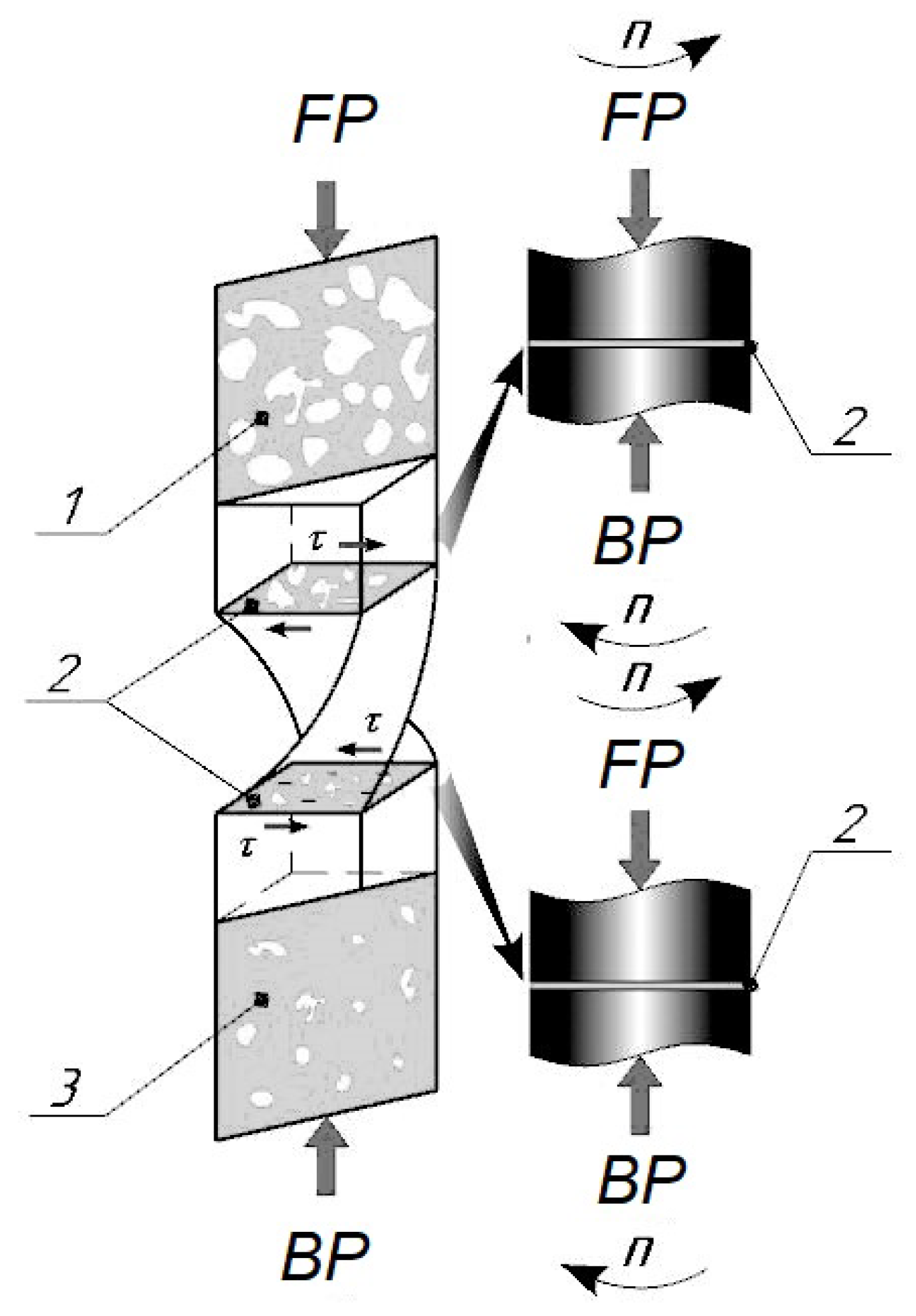
Figure 1.
Deformation of a porous billet by twist extrusion: 1—before TE; 2—deformation zone; 3—after TE, —forward pressure, —back pressure.
Figure 1.
Deformation of a porous billet by twist extrusion: 1—before TE; 2—deformation zone; 3—after TE, —forward pressure, —back pressure.

Figure 2.
Axial compressor.

Figure 3.
Profile of the first stage blade.

Figure 4.
Structural model.

Figure 5.
Airflow model of the compressor.

Figure 6.
Pressure and temperature field on blade surfaces.

Figure 7.
Temperature field for blades and vanes of stage 6.

Figure 8.
Von Misses stress in blades and vanes made from VT8_spk_spd in engine emergency mode.

Figure 9.
Material maximum temperature vs the operating temperature of compressor stages.

Figure 10.
Rotor and stator stages for which the strength and temperature limits of materials are met.
Figure 10.
Rotor and stator stages for which the strength and temperature limits of materials are met.

Figure 11.
Materials recommended for individual compressor stages.


Table 1.
Small gas-turbine engines. Data from minijets.org, uasresearch.org, wikipedia.org and [2,3,8].
Table 1.
Small gas-turbine engines. Data from minijets.org, uasresearch.org, wikipedia.org and [2,3,8].
| Producer | Model | Thrust | Weight | Thrust | Length | Diameter | Platform |
|---|---|---|---|---|---|---|---|
| kN | kg | /Weight | mm | mm | |||
| Turbomeca | Arbizon IIIB2 | 4.02 | 115 | 3.56 | 1361 | 421 | Otomat missile |
| Microturbo | TRI 60-30 | 5.70 | 61 | 9.53 | 841 | 343 | Apache missile |
| Teledyne CAE | J402-CA-702 | 4.20 | 63 | 6.85 | 762 | 317 | MQM-107D Streaker |
| HAL | PTAE-7 | 3.72 | 65 | 5.83 | 1270 | 330 | Lakshya PTA drone |
| Mitsubishi | TJM4 | 2.84 | 56 | 5.19 | 1092 | 355 | Subaru drone |
| Williams Int. | F107WR402 | 3.11 | 66 | 4.60 | 1262 | 305 | BGM-109 Tomahawk |
| Motor Sich | MS-400 | 3.92 | 85 | 4.70 | 850 | 320 | R-360 Neptune missile |
| Ivchenko Progress | AI-305 | 3.04 | 61 | 5.08 | 650 | 232 | Ultra light aircraft |
| Soyuz | R95-300 | 3.55 | 100 | 3.62 | 850 | 315 | Kh-55 missile |
| Saturn | 36MT | 4.54 | 100 | 4.63 | 850 | 330 | Kh-59 missile |
| Price Induction | DGEN 380 | 2.55 | 85 | 3.06 | 1126 | 469 | Personal Light Jet |
Table 2.
Analysed alloys, their composition and related publications.
| VT8 (Ti-6.8Al-3.5Mo-0.32Si), OST 190013-81, GOST 26492-85, [25,26,27,28,29,30,31] | |||||||||||
|---|---|---|---|---|---|---|---|---|---|---|---|
| Composition % mass | Impurities % max | ||||||||||
| Ti | Al | Mo | Sn | Si | C | Fe | Zr | O | N | H | |
| base | 5.8–7.0 | 2.8–3.8 | ≥0.4 | 0.2–0.4 | 0.1 | 0.3 | 0.5 | 0.15 | 0.05 | 0.015 | |
| -TiAl (Ti-46Al-5Nb-2W), [32,33,34] | |||||||||||
| Ti | Al | Nb | W | ||||||||
| Base | 44–47 | 4.2–5.5 | 1.5–2.5 | ||||||||
| 7055+Sc (Al-Zn-Mg-Cu-Sc), OST 190013–81, [35,36,37,38,39,40] | |||||||||||
| AI | Zn | Mg | Cu | Zr | Sc | Fe | Mn | Si | Ti | Cr | Ni |
| base | 6.8–8.4 | 1.5–2.5 | 1.6–2.9 | 0.1–0.5 | 0.1–0.25 | 0.13 | 0.01 | 0.03 | 0.01 | 0.01 | 0.01 |
Table 3.
Mechanical and physical properties of the alloys considered for compressor aerofoils.
| E | ρ | UTS | σ0.2 | ν | E/ρ | UTS/ρ | Tmax °C | |
|---|---|---|---|---|---|---|---|---|
| Material | MPa | kg/m3 | MPa | MPa | Nm/kg | Nm/kg | ||
| VT8 | (1.20 ± 0.05) e5 | 4520 ± 198 | 980 ± 42 | 850 ± 38 | 0.30 | 26.5 e6 | 0.22 e6 | 500+20 |
| VT8_spd | (1.08 ± 0.04) e5 | 4400 ± 201 | 1250 ± 34 | 1150 ± 44 | 0.38 | 24.5 e6 | 0.28 e6 | 460+20 |
| VT8_spk | (0.95 ± 0.04) e5 | 4000 ± 226 | 700 ± 40 | 450 ± 42 | 0.10 | 23.8 e6 | 0.18 e6 | 500+20 |
| VT8_spk_spd | (1.10 ± 0.05) e5 | 4400 ± 180 | 1040 ± 35 | 960 ± 36 | 0.32 | 25.0 e6 | 0.21 e6 | 460+10 |
| -TiAL | (9.50 ± 0.43) e4 | 4200 ± 189 | 720 ± 32 | 650 ± 29 | 0.30 | 22.6 e6 | 0.17 e6 | 750+20 |
| -TiAL_spd | (8.50 ± 0.38) e4 | 4100 ± 166 | 920 ± 30 | 880 ± 36 | 0.34 | 20.7 e6 | 0.22 e6 | 680+10 |
| 7055+Sc | (6.90 ± 0.30) e3 | 2700 ± 121 | 75 ± 3 | 60 ± 3 | 0.33 | 2.6 e6 | 0.03 e6 | 120+20 |
| 7055+Sc_spd | (6.20 ± 0.30) e3 | 2680 ± 114 | 203 ± 7 | 180 ± 7 | 0.35 | 2.3 e6 | 0.08 e6 | 100+10 |
UTS—ultimate tensile strength, SPD—alloy of a submicrocrystalline structure formed by TE SPK (sintered metal powder)—alloy obtained by powder metallurgy methods.
Table 4.
Number of compressor blades.
| Compressor Stage | R1 | R2 | R3 | R4 | R5 | R6 |
|---|---|---|---|---|---|---|
| Number of blades | 37 | 43 | 59 | 67 | 73 | 81 |
Table 5.
Equivalent stress and static safety factor of blades made from candidate materials.
| Rotor Stage | R1 | R2 | R3 | R4 | R5 | R6 | ||||||
|---|---|---|---|---|---|---|---|---|---|---|---|---|
| σmax | SF | σmax | SF | σmax | SF | σmax | SF | σmax | SF | σmax | SF | |
| Alloy/Process | MPa | MPa | MPa | MPa | MPa | MPa | ||||||
| VT8 | 480.2 | 1.77 | 481.1 | 1.77 | 805.8 | 1.05 | 893.3 | 0.95 | 717.6 | 1.19 | 864.5 | 0.98 |
| VT8_spd | 481.9 | 2.39 | 451.6 | 2.25 | 802.4 | 1.43 | 859.4 | 1.34 | 718.4 | 1.60 | 889.4 | 1.29 |
| VT8_spk | 477.2 | 0.94 | 517.3 | 0.87 | 801.2 | 0.56 | 938.6 | 0.48 | 719.9 | 0.63 | 882.2 | 0.51 |
| VT8_spk_spd | 481.7 | 1.99 | 474.2 | 2.02 | 804.3 | 1.91 | 886.0 | 1.08 | 717.4 | 1.33 | 872.2 | 1.10 |
| TiAl | 483.6 | 1.34 | 473.6 | 1.37 | 803.1 | 0.81 | 892.3 | 0.73 | 717.2 | 0.91 | 873.5 | 0.74 |
| TiAl_spd | 483.6 | 1.82 | 462.9 | 1.90 | 801.3 | 1.10 | 877.3 | 1.00 | 717.5 | 1.23 | 885.5 | 0.99 |
| 7055+Sc | 460.0 | 0.13 | 451.1 | 0.13 | 789.8 | 0.08 | 877.0 | 0.07 | 717.0 | 0.08 | 922.4 | 0.07 |
| 7055+Sc_spd | 460.0 | 0.39 | 450.9 | 0.40 | 789.0 | 0.23 | 868.7 | 0.21 | 717.3 | 0.25 | 928.3 | 0.19 |
Table 6.
Equivalent stress and static safety factor of vanes made from candidate materials.
| Stator Stage | S1 | S2 | S3 | S4 | S5 | S6 | ||||||
|---|---|---|---|---|---|---|---|---|---|---|---|---|
| σmax | SF | σmax | SF | σmax | SF | σmax | SF | σmax | SF | σmax | SF | |
| Alloy/Process | MPa | MPa | MPa | MPa | MPa | MPa | ||||||
| VT8 | 8.8 | 96.2 | 45.5 | 18.7 | 54.0 | 15.8 | 133.5 | 6.4 | 140.6 | 6.1 | 142.4 | 6.0 |
| VT8_spd | 8.9 | 129.7 | 43.6 | 26.4 | 53.8 | 21.4 | 128.4 | 9.0 | 140.8 | 8.2 | 146.5 | 7.9 |
| VT8_spk | 8.8 | 51.3 | 48.9 | 9.2 | 53.7 | 8.4 | 140.2 | 3.2 | 141.1 | 3.2 | 145.3 | 3.1 |
| VT8_spk_spd | 8.8 | 84.6 | 44.8 | 16.7 | 53.9 | 13.9 | 132.4 | 5.7 | 140.6 | 5.3 | 143.6 | 5.2 |
| -TiAl | 8.9 | 73.0 | 44.8 | 14.5 | 53.8 | 12.1 | 133.3 | 4.9 | 140.5 | 4.6 | 143.8 | 4.5 |
| -TiAl_spd | 8.9 | 98.9 | 43.7 | 20.1 | 53.7 | 16.4 | 131.1 | 6.7 | 140.6 | 6.3 | 145.8 | 6.0 |
| 7055+Sc | 8.5 | 7.1 | 42.6 | 1.4 | 52.9 | 1.1 | 131.0 | 0.5 | 140.5 | 0.4 | 151.9 | 0.4 |
| 7055+Sc_spd | 8.5 | 21.3 | 42.6 | 4.2 | 52.9 | 3.4 | 129.8 | 1.4 | 140.6 | 1.3 | 152.9 | 1.2 |
Publisher’s Note: MDPI stays neutral with regard to jurisdictional claims in published maps and institutional affiliations. |
© 2020 by the authors. Licensee MDPI, Basel, Switzerland. This article is an open access article distributed under the terms and conditions of the Creative Commons Attribution (CC BY) license (http://creativecommons.org/licenses/by/4.0/).
Share and Cite
MDPI and ACS Style
Pavlenko, D.; Dvirnyk, Y.; Przysowa, R. Advanced Materials and Technologies for Compressor Blades of Small Turbofan Engines. Aerospace 2021, 8, 1. https://0-doi-org.brum.beds.ac.uk/10.3390/aerospace8010001
AMA Style
Pavlenko D, Dvirnyk Y, Przysowa R. Advanced Materials and Technologies for Compressor Blades of Small Turbofan Engines. Aerospace. 2021; 8(1):1. https://0-doi-org.brum.beds.ac.uk/10.3390/aerospace8010001
Chicago/Turabian StylePavlenko, Dmytro, Yaroslav Dvirnyk, and Radoslaw Przysowa. 2021. "Advanced Materials and Technologies for Compressor Blades of Small Turbofan Engines" Aerospace 8, no. 1: 1. https://0-doi-org.brum.beds.ac.uk/10.3390/aerospace8010001
Note that from the first issue of 2016, this journal uses article numbers instead of page numbers. See further details here.