Novel 3U Stand-Alone CubeSat Architecture for Autonomous Near Earth Asteroid Fly-By


1
Space Systems Engineering, Faculty of Aerospace Engineering, Delft University of Technology, Kluyverweg 1, 2629 HS Delft, The Netherlands
2
Hyperion Technologies, Vlinderweg 2, 2623 AX Delft, The Netherlands
3
University of Strathclyde, 16 Richmond Street, Glasgow G1 1XJ, UK
*
Author to whom correspondence should be addressed.
Aerospace 2021, 8(1), 9; https://0-doi-org.brum.beds.ac.uk/10.3390/aerospace8010009
Submission received: 30 October 2020
/
Revised: 15 December 2020
/
Accepted: 18 December 2020
/
Published: 30 December 2020
(This article belongs to the Special Issue Small Satellite Technologies and Mission Concepts)
Abstract
:The purpose of this work is to present a novel CubeSat architecture, aimed to explore Near Earth Asteroids. The fast growth in small satellite commercial-off-the-shelf technologies, which characterized the last decade of space industry, is exploited to design a 3U CubeSat able to provide a basic scientific return sufficient to improve the target asteroid dataset. An overview of the current available technologies for each subsystem is presented, followed by a component selection driven by the mission constraints. First a typical asteroid fly-by mission is introduced together with the system and performance requirements. Then each characterizing subsystem is critically analyzed, and the proposed configuration is presented, showing the mission feasibility within only 3.9 kg of wet mass and 385 m/s of total .
1. Introduction
Near Earth Asteroids (NEAs) represent one of the most challenging and interesting mission targets of the next decades of Solar System exploration. The three main reasons behind this deep interest are related to scientific exploration, planetary protection, and in-situ resources exploitation [1,2]. All the major space agencies worldwide have shown a significant interest towards NEAs (and small bodies in general), testified by many under development or successfully flown missions. Examples of these are NASA Osiris-Rex [3], JAXA Hayabusa-2 [4], NASA DART [5], and ESA Hera [6].
Due to the large number of small bodies populating the Solar system, an extensive characterization can be possible by increasing the number of visited targets. However, this can come only with a complete change of mindset, which should follow three main trends: autonomy, standardization, and miniaturization.
CubeSats have been widely considered both as stand-alone spacecraft and as secondary payloads of larger spacecraft. Juventas [7] and the (recently re-named) Milani CubeSats will accompany the Hera spacecraft towards 65803 Didymos (1996 GT) [6,8], while M-Argo [9] and NEAScout [10] are stand-alone CubeSats that will rendezvous with an asteroid, respectively, using low-thrust electric propulsion and solar sail. This shows that miniaturization is attracting the scientific community worldwide, but improvements can be done for autonomy and standardization. The former represents the possibility of limiting the support from the ground segment through autonomous operation and navigation. This as of today has been investigated in both close proximity relative navigation [11] and interplanetary cruise [12]. The latter exploits the use of commercial-off-the-shelf (COTS) components to limit the cost and time associated to the development and integration of new components.
Taking all of this into account, this work is aimed to explore the possibility of designing a 3U CubeSat architecture based exclusively on COTS components, not depending on the particular target asteroid, and allowing mass production at low per-unit cost. Deployment around the Earth is considered. In Reference [13], an interesting 3U CubeSat architecture, aimed to fly-by a NEA, is explored. The mission concept is based on the deployment around Sun-Earth L1-L2 points (supposing a piggyback rideshare of a larger mission), and on a semi-autonomous navigation approach. However, these mission characteristics impose different constraints (especially on mass and volume budgets), which reflect in a different architecture approach. In fact, the architecture presented here requires a larger propulsion system, due to the different deployment, which lead to more rigid packing constraints for the other subsystems, both in terms of mass and volume.
In Reference [14], an interesting mission concept involving 3U CubeSats is explored. The feasibility and utility of using CubeSats for asteroid exploration, as secondary payload of a larger spacecraft, is demonstrated. In particular, the proposed mission architecture is based on two 3U CubeSats, deployed in the close proximity of the target, which perform a detachment to achieve the final configuration of one 2U and four 1U CubeSats.
This paper is then intended to show the feasibility of a stand-alone, compact (3U), and low-cost solution to explore NEAs, as the currently under development CubeSats for such missions are characterized by architectures larger than 6U. Moreover, this paper contributes to the literature by presenting proper COTS components performance analysis, and trade-off selection for each characterizing subsystem, reviewing, describing, and analyzing in depth the characteristics of the required components for such missions.
This paper is organized as follows—first, typical NEA fly-by mission is described and characterized in order to derive mission requirements and characteristics. Afterwards, autonomous navigation phases are described and analyzed, focusing on a fully-autonomous strategy. Then, all the subsystems are presented, and their COTS options are evaluated and selected. Finally, after mass/volume/power budgets are defined, the final configuration is presented, highlighting pros and cons, and comparing it with two reference 3U architectures. Recommendations to make this configuration a good option for NEAs are reported.
2. Mission Description
Several mission concepts have been proposed to explore NEAs (and small bodies in general). Usually, proposals consist of a mothership carrying several CubeSats on-board [6,8], or stand-alone missions [9,10]. These missions are based on either a rendezvous or a fly-by of the target. The former usually allows a more extensive exploration of the target, but it also requires a significantly larger , which complicates the design of a small and low-cost CubeSat. The latter has a significantly shorter scientific phase, but with a much smaller and a simpler communication subsystem design.
The mission concept presented in this paper is characterized by a NEA fly-by achieved after an Earth’s escape, which is in line with the current space exploration trend. A single fly-by approach has been chosen against multiple ones (sometimes referred as ‘NEAs tour’) for two main reasons: first, exploring multiple targets with a 3U architecture appears not to be feasible, especially for the limited propellant mass which can be stored on-board; secondly, it is cost-effective due to the standardization related to CubeSats with the same design. Moreover, a fully autonomous and COTS 3U CubeSat configuration is considered, in order to minimize the launch mass and volume, as well as the cost. The mission concept can be described by a Mission Objective (MO) and a Mission Philosophy (MP):
- MO: improve target Near Earth Asteroid dataset in terms of dimension, shape, rotational parameters, composition and ephemerides.
- MP: maximize the scientific return with limited cost, by COTS components, autonomous operations and Guidance, Navigation, and Control (GNC), commercial launcher, small size, and standard architecture.
MO and MP translate in Mission Requirements (MR), summarized in Table 1.
The mission phases are described in Table 2. The CubeSat is released in an injection orbit around the Earth and it is de-spinned. Then, propulsion system is turned on to inject the CubeSat in an Earth’s escape trajectory, followed first by the interplanetary cruise and then by the close encounter phase (defined by the navigation switch from absolute to relative). Following the scientific phase, the acquired data are transmitted to the ground segment, and finally the spacecraft is injected (if necessary) in its final disposal trajectory. The duration of each phase varies depending on the selected NEA target. Table 2 reports typical values that can be expected from each phase.
As injection orbit, a Super Synchronous Geostationary Transfer Orbit (SSGTO) has been selected, due to its high energy and commercial nature, which would further decrease the costs. SSGTO is characterized by apogee and perigee altitudes respectively of 295 km and 90,000 km.
3. Autonomous Navigation
For such compact (in mass and volume) and low-cost configurations, autonomous navigation is required during the mission phases in order to reduce ground tracking demand and to avoid large communication subsystems (MR3 in Table 1). The mission phases defined in Section 2 highlight three different navigation phases:
- Earth’s relative navigation during ID and EE;
- absolute heliocentric navigation during DSC, DT, and FD;
- relative navigation during CE and SA.
The first phase can be accomplished (at least partially) by means of Global Navigation Satellite System (GNSS) receivers, which with low volume, mass and power consumption can provide high orbit determination accuracy in Low-Earth Orbit (LEO). Hyperion Technologies GNSS200 [15] is an example of low volume (below 0.001 U), low mass (3 g) and low power consumption (below 150 mW peak) receiver able to provide below 8 m orbit determination accuracy. Clearly, orbit determination accuracy would significantly drop as long as the CubeSat is far from the Earth. Then, during the apogee raising escape trajectory, discussed later in the Propulsion subsection, the orbit determination process via GNSS can be improved by merging with optical navigation, which is exploited in the second phase. Moreover, when the CubeSat is approaching the perigee of the SSGTO, the high orbital velocity (∼10.5 km/s compared to the ∼7.5 km/s of a LEO orbit) may influence the orbit determination accuracy. The GNSS receiver orbit determination accuracy evaluation along the escape trajectory, eventually in coupling with optical navigation strategies, is left for future works. The navigation accuracy at the end of the escape trajectory influences the initial conditions for the second navigation phase. To compensate the currently not available accuracy, large initial conditions uncertainties in the second phase have been considered.
In deep-space missions, the second navigation phase usually relies on ground tracking. The only two CubeSats which flown in deep-space as of today, JPL MarCO-A and –B, carried on-board JPL Iris transponder, and the navigation team exploited both ranging and Doppler tracking for position estimate [16]. This well proven technique however does not fit a compact 3U configuration in terms of mass and volume, and in terms of cost since it would rely on ground tracking. The optimal solution for such configuration would be the use of already on-board instrumentation, adapted for autonomous navigation purposes. This is the case of optical line-of-sight navigation via star trackers, which exploits the directions of visible bodies (planets, moons, asteroids), together with their actual position from on-board stored ephemeris, to estimate the state of the spacecraft in deep-space [12,17,18,19]. This technique has a clear geometrical limitation due to the relative positions between observer (CubeSat) and tracked objects, which can be excluded from the Field-of-View (FOV) due to the Sun disk and/or blinding. Each target, with different departure times and different shapes of the orbit, will have its customized tracking strategy, which will moreover depend on whether the trajectory is low-thrust with relatively fixed attitude, or ballistic with a flexible attitude, during which the CubeSat can orientate to track a particular celestial object.
The required accuracy at the end of the cruise depends on target NEAs characteristics and CubeSat hardware constraints. First, to have a fully autonomous navigation system, the CubeSat cannot receive updated target ephemeris from ground and it has to rely on propagated ephemeris stored on-board prior to launch time; so the state of the NEA target at the fly-by time will have a propagated covariance matrix associated to it, which will depend on the Time-of-Flight (ToF)—the larger it is the larger is the propagated uncertainty (as a rule of thumb). Moreover, each NEA is characterized by different size, shape, composition, and albedo, which together influence its brightness; in general they are faint objects, which can become visible in the FOV of the instrument (star tracker in this case), only few days before the fly-by. The latest the asteroid appears in the FOV, the smaller will be the achievable displacement (from nominal encounter position) to compensate position uncertainties (for given availability), obtainable with a Trajectory Correction Maneuver (TCM). Asteroid apparent brightness can be modeled as [20]:
where d is the relative distance NEA-observer, r the relative distance NEA-Sun, the phase illumination angle, defined as the angle between the observer-target and Sun-target directions, H the absolute magnitude, and G the slope parameter. Off-the-shelf micro star trackers have a minimum detectable visible magnitude below 7.0 [21]. Setting the visual magnitude (to 7.0), the maximum relative distance CubeSat-target for the observation can be quantified, as a function of phase angle and Sun-NEA distance. Then, the number of days before the fly-by the asteroid becomes visible can be obtained, by linearly approximating the close approach. This value, together with the available budget, influences how much the spacecraft trajectory can be corrected, once the asteroid is visible.
Merging everything together, it is possible to preliminary compute the required accuracy at the end of the cruise for a particular NEA target. Figure 1 reports this process for the asteroid (433) Eros, taken as a target example. In (a) the number of days prior to the fly-by the NEA becomes visible is evaluated as a function of phase angle and distance NEA-Sun. Due to its brightness, in the best illumination condition, it becomes visible in the FOV only 9 days before the fly-by. A more realistic number oscillates between 6 and 7 due to the real approach angle, which it should be zero at the closest approach time to have the full asteroid disk in the FOV of the payload; assuming 8 days, which corresponds to if the fly-by occurs close to the target perihelion, it is possible to compute the displacement from the nominal encounter position as a function of the available impulsive . The achievable displacement with only one impulsive TCM of 15 m/s is around 10,000 km (b). Combining these two considerations with the ephemeris uncertainty propagation, which depends on the initial uncertainty and on the ToF, it is possible to define a navigation position requirement at the end of the cruise. For Eros, a 2-body problem propagation of around 300 days (typical ToF) leads into a uncertainty in the order of few thousands kilometers, which translates into a navigation requirement of maximum 2000 km, if a budget below 5 m/s is available; if a larger budget is available, and possibly also more days prior to fly-by, this requirement could be less stringent. Finally, (c) shows the accuracy of the navigation filter (Extended Kalman Filter) in the last 60 days of the cruise (assumed as a Hohmann transfer), which meets the requirement. Both Jupiter and Mars are observed with a tracking rate of one observation/hour for all the duration of the cruise, with a line-of-sight measurement accuracy of 10 arcsec (as it corresponds to micro star tracker accuracy). The assumed initial position and velocity uncertainties are respectively km and km/s, accordingly to previous works [17]. It is necessary to remark that both navigation performance and requirements will depend on the specific target and mission design, but in general, this navigation technique appears suitable. Moreover, as reported in Reference [21], the time to correct the trajectory towards the asteroid can be further reduced, as the asteroid should be observed sufficiently to compute accurately its trajectory and to plan the maneuver. Again, this will depend on the particular target, but it is important to be taken into account for further navigation analysis.
The third navigation phase is widely investigated nowadays and it is strongly linked to the scientific phase, since it can use the same instrumentation (visible camera). It also influences the quality of the scientific return. Relative navigation around an asteroid is challenging due to the various uncertainties of the particular target, from its actual dimension and shape, to its actual mass and rotation characteristics. So, it is important that the navigation system (and strategy) is robust to that uncertainties. Many techniques have been investigated or are under current investigation, from more traditional center-of-brightness and geometric centering [11,22], to brand-new deep-learning and neural network based [23,24]. Indeed, the fast growth in neural-networks based navigation will characterize the next years of small bodies exploration. A traditional approach based on geometrical features and surface landmarks appears more suitable for this application, since, as of today, deep-learning based approaches are still under investigation; however, in the near future, when their high performances and robustness will be proved, they will be optimal for this application.
4. Subsystems Analysis
As reported in Reference [25], the physical architecture of a satellite can be defined as the foundation on which all its functions and performance is built upon. So it comprises the satellite breakdown in physical subsystems and components, their location, and their structural and electrical interfaces. The majority of CubeSat architectures is based on modular stack of printed circuit boards (PCBs), and each of the subsystems is represented by one (or more) PCBs. Beside the classical approach, innovative architectural concepts have been proposed through the years: cellular, panel, plug-and-play, and lean electrical interfaces.
The following sections are intended to define all the relevant subsystems, presenting the available COTS options, and evaluating their performances and applicability for the mission concept. First, the payload (and the scientific return) is analyzed. Then, one by one, the subsystems composing the spacecraft bus are evaluated, starting from the propulsion system, that due to its large mass and volume, will be one of the driving subsystems.
4.1. Payload
Exploration of NEAs is linked to three main objectives: scientific research on the evolution of the solar system, planetary protection, and in-situ resources exploitation. The common point of these objectives is the poor information on the asteroid. By ground observations, it is not possible to retrieve accurate information on physical parameters (actual shape, dimension, rotational parameters), composition (surface and inner), mass, and even ephemeris. A small and low-cost CubeSat for NEAs exploration can be useful to enlarge the available dataset, performing basic observation during in-situ exploration. A Visible (VIS) range camera can be used to determine the actual shape, dimension, and rotational rate and axis. Moreover, it is needed for optical relative navigation, and merged relative and absolute navigation data can be used to improve asteroid ephemeris. Composition can be retrieved by means of InfraRed (IR) observation. Determining mass and/or density is however less straightforward, and some techniques and mission proposals identified solutions to the problem. One option would be to use a pair of CubeSats to fly-by the asteroid, and measuring their relative distance before, during, and after the encounter, information on the mass can be retrieved [26]. Sticking to the concept of only one CubeSat, the Yarkovsky effect can be exploited to estimate the mass of the asteroid [27]; to do that, rotational parameters, composition (thermal inertia), and temperature distribution are needed. However a large set of ground observation is needed. Based on these considerations, mass/density estimation can be assumed as a second level mission objective. Third level mission objectives can be connected to measuring magnetic field residuals. Off-the-shelf magnetometers (usually also already integrated in Attitude Determination and Control System (ADCS) for attitude determination purposes) are available with tiny mass, volume, and power consumption. Keeping in mind that they would not affect significantly the mass and volume budgets, they are not considered for this mission concept.
To satisfy the mission objectives, based on previous considerations, a visible camera and IR spectrometer compose the minimum set of payload required for such missions (MR6 in Table 1). Usually the scientific payload is the most customized subsystem for a space mission, since it strongly depends on the objectives. Moreover, as of today, not many COTS payloads are available on the market, especially considering that they are designed for Earth observation. The 3U configuration further limits the range of applicable instrumentation. While only one off-the-shelf option for IR spectrometer is available (Thoth Technology Argus 2000 [28]), a larger range of visible cameras is available. However, just a few of them are compact and light enough to be included in a 3U CubeSat (as it will be shown in the Results section). Moreover, Ground Sampling Distance (GSD) needs to be considered. The GSD, measured in m/pixel and defined as the ground distance between two adjacent pixels of the captured image, quantifies the accuracy with which the asteroid shape can be described. As long as the GSD decreases, a larger number of pixels will be employed to describe the target. Due to the various sizes, shapes, and possible fly-by altitudes of the targets, it is not straightforward to derive a unique requirement for the GSD, but a maximum value of 50 m/pixel at 300 km altitude can be defined; this requirement would allow to describe with at least 6 × 6 pixels a 300 m diameter NEA, which is assumed as the minimum fair value for both the scientific output and relative navigation, as it should allow to reconstruct basic asteroid shapes and to perform centroiding in case of partial illumination of the surface. Clearly, the lower the GSD is, the better the scientific output and navigation accuracy will be. A proper characterization of the required minimum number of pixels describing the asteroid is left for future works, as it will depend on many factors such as the techniques to extract information from the images, and on the actual fly-by altitude, which can be triggered based on hardware constraints.
Based on the product datasheet available on the market, it is possible to retrieve the GSD at a certain altitude, or, when the values are not available, the GSD at a certain altitude can be approximately computed from basic camera characteristics as:
where h is the altitude, the sensor width, the image size in pixels, and F the focal length. Based on Equation (2), Figure 2 reports the GSD as a function of the fly-by altitude for the most promising COTS cameras and for ASPECT [9], a Multi-spectral imager from VTT, that will be employed by ESA M-Argo. It is characterized by three acquisition channels (VIS, NearIR and ShortWave IR) and, even if it is not a COTS instrument, its small volume (1U), mass (950 g), and power consumption (7 W), make it a valid candidate alternative to the COTS camera and spectrometer, especially for larger applications.
Other off-the-shelf components have not been included in the comparison, such as Crystal Space Micro Camera System [29] and XCAM C3D [30]. They represent very compact solutions in terms of mass, size, and power consumption, but their GSD is not sufficient to guarantee a significant scientific return.
Hyperion Technologies IM200 [31] appears as the most promising solution in terms of mass and volume. Moreover, it can be used also as a navigation camera (NAVCam), as it has been discussed in the Navigation section. For larger CubeSats, where mass and volume requirements can be less strict, SCS Space Gecko Imager [32] represents an excellent alternative in terms of accuracy. If the requirements are even less strict, Simera Sense HyperScape100 and Simera Sense MultiScape100 would ensure an incomparable resolution together with the possibility of performing VIS and NIR measurements with the same instrument [33]. Due to its low mass and volume, Hyperion Technologies IM200 will be considered for this architecture.
Argus 2000 represents the only currently available off-the-shelf IR spectrometer, and its IR range is smaller than ASPECT’s range (1240–2000 nm compared to 900–2500 nm). Moreover, its narrow FOV (∼0.15) poses several challenges in a 300–500 km fly-by altitude. Nevertheless, its mass (300 g) and volume (∼0.3 U) make it perfectly suitable for this application.
The preliminary considerations and analysis reported in this section are useful to get an idea of the typical (and minimum) payload that a low-resources spacecraft, aimed to explore NEAs, should carry on-board. It is clear that the option for a custom payload cannot be excluded, as the obtainable scientific return is strongly influenced by actual hardware, whose design is therefore linked to the techniques to extract data. As an example, the technique to obtain the shape of the target from the image influences the requirement on the GSD. Similar argumentation can be derived for the rotational parameter or composition characterization. So, in the Results section, when the mass and volume budgets are presented, configurations with and without payload are defined, in order to characterize the allowable mass and volume for an eventual custom payload.
4.2. Propulsion System
The micro-propulsion system is usually the largest and the most demanding in terms of mass and volume, thus it is seen as one of the driving subsystems for this mission (MR7 in Table 1). Moreover, commercial launches are more frequent than deep-space ones (respectively around five per year and one per year), so they can be used as a rideshare more easily [34]. For this reason an Earth sphere-of-influence (SOI) escape scenario is considered, with the goal of achieving a transfer able to fly-by an asteroid. The Earth escape problem has been investigated in previous work and solutions have been proposed—chemical propulsion followed by electric low-thrust trajectory [34], low-thrust escape trajectory [35], and micro-propulsion staging [36]. However, all of these solutions consider customized propulsion systems, which are not in line with the off-the-shelf approach used in this mission concept.
Both chemical and electric micro propulsion systems are evaluated, following respectively two simplified approaches for high-thrust and low-thrust applications.
4.2.1. Chemical Micro-Propulsion
NASA-JPL Small Body Database Browser [37] has been used to preliminary compute the required Earth’s SOI escape velocity, , to inject the spacecraft in an interplanetary transfer towards the target NEA. The Mission Design Tool solves the Lambert problem and provides Pork-Chops plots. It allows the user to enter the name or code of a particular asteroid, giving back information on a mission to the specified target, such as required escape velocity, the ToF, and departure date. Table 3 gives a short list of targets with their departure dates, ToF, and required escape velocity, which have been chosen as the minimum solutions, but not all meet MR4.
Recalling the SSGTO injection orbit, and using the patched conics approach, it is possible to compute the approximated to deliver to the spacecraft at the perigee, to inject it on an escape hyperbola:
where is the hyperbolic excess velocity, is the Earth gravitational parameter, and and are respectively the radius and velocity at the perigee of the SSGTO. Based on Equation (3), Figure 3 shows the relation between the escape velocity and the perigee . As it is shown in the plot, 385 m/s of budget will ensure a hyperbolic excess velocity higher than 0.6 km/s. Considering that 0.6 km/s is the largest escape velocity considered in Table 3, 385 m/s can be assumed as a general requirement for the escape trajectory, the TCM(s), and wheels de-saturation. TCM has been described in the Navigation section, while wheels de-saturation will be discussed in the ADCS section. Further studies can be done in order to define the optimal escape strategy, which due to the limited burning time of the micro-propulsion system, can be fractionated in sequential apogee raising maneuvers.
Having defined a general requirement, the micro-propulsion system can be evaluated. Solid propellant thrusters are not considered, because they would allow one (or few) burn only, if no customized solutions are designed. On the other hand, cold gas micro propulsion systems are characterized by low specific impulse. Therefore, liquid mono- and bi-propellant micro-propulsion systems represent the best solution to inject the CubeSat to a transfer trajectory towards a NEA. On the market, both single thrusters and complete integrated micro-propulsion systems are available. The former allows a more customized sizing in terms of propellant mass, while the latter allows the integration of a ready-to-use micro-propulsion system. Figure 4a reports the relation between required specific impulse and propellant mass to deliver 385 m/s to a CubeSat with a varying Beginning-Of-Life (BOL) mass, reporting in the chart the micro-propulsion systems with their characteristics; the comparison is between: VACCO MiPS [38], VACCO ArgoMoon MiPS [39], Aerojet Rocketdyne MPS-130 [40], Aerojet Rocketdyne MPS-120 [41], Busek BGT-X5 [42], NanoAvionics EPSS C1 [43], Hyperion Technologies PM200 and PM400 [44], and Tethers Unlimited HYDROS-C [45]. Figure 4b shows the performances of three ECAPS HPGP thrusters [46], taking into account the different thrusters mass. Both plots have been obtained from the rocket equation. From the evaluation chart, the most promising solution is the Aerojet Rocketdyne MPS-130 1U [40], a mono-propellant micro propulsion system able to provide 385 m/s of to a CubeSat of 3.9 kg. ECAPS HPGP 0.1 N thruster may offer either higher or the same to a heavier CubeSat; however, it would require an additional design of the rest of propulsion system (tank, feeding systems, etc.), which would make the architecture not off-the-shelf.
The selection of the Aerojet Rocketdyne MPS-130 defines then the mass and volume requirements for the architecture and the other subsystems, which need to fit the remaining 2U. Moreover, as this engine is able to deliver the required to a CubeSat of maximum 3.9 kg, and it is characterized by a BOL mass of 1.7 kg, the remaining components of the architecture should not exceed 2.2 kg of mass. This, again, shows that mass and volume for each component are driving parameters for the selection.
4.2.2. Electric Micro-Propulsion
Electric micro-propulsion systems evaluation requires the generation of low-thrust trajectories, whose design (and optimization) is not an easy process. JPL Small-Body Database Browser Mission Design Tool gives some reference values for low-thrust trajectories towards certain asteroids.
Trajectory optimization for NEAs fly-by has been widely explored in recent years, showing the feasibility of such missions. In Reference [47], a solar electric propulsion system, with Isp = 1200 s and thrust level at 1 AU equal to 0.006 N, was considered, showing small for more than 10 NEAs, and comparing them with rendezvous missions. In Reference [48], an electrospray thruster characterized by Isp = 2300 s and T = 100 N was considered, and the mission feasibility with low (less than 85 m/s) was demonstrated for more than 40 targets (using as initial condition Sun-Earth Mean Barycenter L1 and L2). However, given the , which can be retrieved from literature, the rocket equation cannot be used to compute the required propellant mass, since it is based on a constant ejection velocity assumption. This is clearly not the case of low-thrust trajectory with electric thrusters, which are based on a variable thrust. This limits the applicability of previous studies for preliminary evaluation of COTS electric micro-propulsion systems for asteroid fly-by. Indeed, the best approach would be passing through an optimization process for each thruster, giving as output the required control law to reach the target. However, a shape-based low-thrust trajectory design approach can be exploited to preliminary quantify the amount of propellant mass needed to reach the target, without passing through a proper optimization process. The spherical coordinates shaping trajectory design approach [49], as the name suggests, is based on imposing the shape to the trajectory, constraining the initial condition (Earth) and the final condition (target asteroid). It can be used to generate a first guess solution before the optimization, as it is done in Reference [47].
The method is particularly suited for rendezvous low-thrust trajectory design, since it imposes the match with the velocity and position of the target asteroid as final condition. Since usually rendezvous missions are more expensive than a fly-by from the required (and the propellant mass) perspective, this method is not perfectly suited for a fly-by trajectory design, since it would overestimate the required propellant mass. However, the shaping method solution, which can differ significantly from the optimal one, can be triggered towards the fuel optimal solution by means of some particular constraints and by means of three grid searches on ToF, departure date (node passage), and final velocity norm.
First, it is possible to constrain the encounter at one of the two nodes (descending or ascending) of the asteroid orbit. This is because NEAs orbits are characterized by a various range of inclinations, and setting the encounter at the node would in principle avoid expensive change-of-plane maneuvers. However this is not sufficient to guarantee no plane changes, because the asteroid velocity at the node is not necessarily coplanar with Earth’s orbit, and since the shaping approach will be based on imposing that final velocity, the resulting trajectory will be expensive and out-of-plane. To limit this, it is possible to impose the final condition (corresponding to the encounter at the node) based on a ‘fictitious’ orbit which has all the same orbital elements with the original asteroid orbit, but the inclination imposed to zero. In other words this translates into a final velocity constraint coplanar with Earth’s orbit, which is sufficient to avoid plane-changes.
Then, now that the approach is ‘preliminary’ optimized, it is possible to perform a grid search based on 3 varying parameters:
- ToF: from 100 to 600 days, with a time step of 10 days;
- Final velocity: from −2 km/s to +2 km/s of the fictitious asteroid velocity at the node, with a velocity step of 0.1 km/s (in order to have a wider range of relative velocities);
- Node passage: the first 10 passages per node (20 in total) after the last ephemerides data available on JPL Small-Body Database Browser (31 May 2020), which translates in around a decade.
Then the minimum is found and from the control acceleration profile it is possible to compute the mass and thrust profiles, as a function of the specific impulse (which is assumed constant) and of the BOL mass set as 4 kg, by imposing a set of equations: 2nd Newton law and mass flow rate equation. Again, the results of this search grid is not necessarily the optimal solution, and it could be improved by extending the final velocity range and by making varying also the in-plane angle. However at this stage it is sufficient to get a rough requirement on propellant mass, that can be eventually increased with a certain margin. The evaluation process has been repeated for the 16 NEAs of Table 3. Table 4 reports the values for ten of them, as the ones with a reasonable propellant mass for a 4 kg CubeSat. The other six (3200 Phaethon, 66391 Moshup, 153201, 142464, 138127, 35107) resulted in extremely large required propellant mass (more than 2.5 kg for a 4 kg CubeSat) and they have been excluded from the table. The other ten showed a maximum required propellant mass of 1.1 kg (for the lowest Isp = 2000 s) and thrust levels within 1.1 mN (with the exception of 4034 Vishnu). Figure 5 reports the extended results for one of the NEAs, 65679.
Considering electric propulsion systems with specific impulse below 2000 s would impact significantly on the propellant mass, affecting the feasibility of the mission. So, Sitael HT-100 [50], Mars Space LTD PPTCUP [51], and Busek BHT-200 [52] are not applicable to this mission.
Higher specific impulse options are Busek BIT-3 ion thruster [53], Mars Space LTD mini RF ion engine [54], and Enpulsion IFM Micro 100 Thruster [55] and Nano Thruster [56]. BIT-3 and IFM Micro 100 micro-propulsion systems have however an off-the-shelf configuration too large for a 3U CubeSat, respectively ∼1.8U and ∼2.2U, which does not leave enough space for the rest of the subsystems. On the other hand Mars Space LTD mini RF is a thruster occupying approximately 0.6U, but no information are at the moment available for tanks, feeding systems and other components. Required propellant mass for Isp = 2500 s oscillate between 0.5 and 1.2 kg, and considering all the components (tank, feeding system, etc.), this thruster would require no less than 1.3U. The large volume, in coupling with the required additional design of the rest of the micro propulsion system (as for the ECAPS HGPG highlighted in the previous subsection), makes this thruster not suitable for this application. Enpulsion IFM Nano thruster occupies a relatively small volume (∼0.8U), with dry/wet mass 0.67/0.9 kg, ensuring a sufficient propellant mass for almost all the ten reachable NEAs (due to a specific impulse up to 6000 s). However, its maximum thrust level of 0.35 mN is not sufficient, since all the analyzed NEAs require peak thrust magnitude of at least 0.8 mN, as reported in Table 4. So, without further analysis, optimizing the trajectory with a limit on the maximum thrust, IFM Nano thruster is not suitable for this application.
The low-thrust trajectory analysis showed that, considering these targets, electric propulsion systems are less performant than chemical ones for a 3U CubeSat. Moreover, it has to be remarked that it has been assumed Earth’s position and velocity as initial conditions, which in a patched conics approach translates into a zero escape velocity from the SOI. So, to these results, the low-thrust escape trajectory has to be added, resulting in even larger propellant consumption. However, electric propulsion applicability cannot be excluded in general, since some optimization techniques may show its feasibility with other NEA targets, but for the purposes of this work, chemical propulsion will be chosen. Additionally, electric micro-propulsion systems usually require larger power consumption than chemical ones, which for a 3U CubeSat imposes several challenges for the power subsystem design. Moreover, for larger CubeSat architectures, where heavier and larger propulsion systems can be integrated, together with larger allowable solar panels delivering higher powers to the subsystems, electric propulsion system overcomes all the problems related to this compact architecture. This is the case of ESA M-Argo, which is aimed to rendezvous a NEA using low-thrust trajectory based on electric propulsion.
Finally, as the Navigation section showed, asteroid visibility times are short. Then, high-thrust chemical propulsion systems are preferred over low-thrust electric propulsion systems, as they allow impulsive maneuvers.
4.3. Attitude Determination and Control System
The ADCS is a combination of several sensors to determine the state of the spacecraft (e.g., Sun sensors, star trackers, hall-sensors, etc.), and actuators to control the orientation of the satellite (e.g., reaction wheels, thrusters). Many companies offer integrated ADCS solutions with all necessary sensors and actuators available, including processors capable of doing most of the computations needed for controlling the satellite. Thus these integrated solutions will be the first focus for the ADCS selection. In terms of functionality and performance for the mission discussed in this paper, pointing accuracy (the degree of accuracy with which the ADCS can point the satellite in a specific direction) is the main parameter influencing the selection of the ADCS. The pointing accuracy is mainly limited by three factors: the FOV of the payload, the directional accuracy required for thrusting maneuvers, and the maximum amount of pointing losses allowed for downlinking data. For the thrust maneuvers no required accuracy is derived as it is expected to be lower than the payload one; moreover, a proper GNC simulation is left for future works, where the pointing accuracy influence on the propulsive maneuvers is simulated and related to fly-by altitude. Thus, it is assumed the two other factors are the main drivers for the pointing accuracy. It is noted here that factors like jitter and agility are also important for the performance of the payload and communication subsystem. However, as this data is not readily available in most cases, the pointing accuracy will be taken as the major selection criterium.
An additional requirements for the ADCS during an asteroid fly-by is related to the relative angular velocity and the payload FOV. The ADCS should allow to dynamically keep track of the target during all the phases of the close approach. The ADCS maximum slew rate should be higher than the maximum relative angular velocity. This assessment depends on the relative velocity and the altitude at the close encounter. Figure 6 reports the relative angular velocity in function of the altitude and relative velocity. Above 450 km of altitude, the required slew rate is below 1.5 also for high relative velocity (12 km/s). As long as the fly-by altitude decreases, the required slew-rate increases. Then, depending on the ADCS available slew rate and relative velocity, the target fly-by altitude may be tuned.
For the actuators it is important that there is sufficient momentum storage in the reaction wheel, or a sufficient of propellant in case of reaction thrusters, and/or that there is a solution to de-saturate the wheels. For most LEO satellites this is done using magnetorquers, but as the magnetic field of the environment is negligible, this is not an option. For most deep-space applications, this problem is solved using reaction thrusters that provide a counter torque during momentum dumping. There are only a few off-the-shelf options for CubeSats in terms of reaction thrusters. One is the Aurora Resistojet Module [57], a water-based resistojet. Due to its chemical-free risk and its 12 thrusters, it is able to properly control and de-saturate the CubeSat. However, the minimum volume and mass configuration (0.3U, 0.35 kg of wet mass) increases the complexity of the design. Another option is the VACCO MiPS cold gas propulsion system, which can be used for both translational and attitude maneuvers. It is similar in size, but only contains 5 thrusters which can be used for all 6 degree-of-freedom [38]. GomSpace offers NanoProp CGP3, a flightproven cold gas propulsion system for 3U CubeSats, characterized by 4 individual thrusters, and by 0.5U volume [58]. All these three options are perfectly suited to de-saturate reactions wheels; Aurora Technologies product occupies a more compact volume, however, as the Results section will show, an additional subsystem, designed exclusively to de-saturate the wheels, poses several challenges in terms of total mass of the CubeSat. For this reason, it is better to rely on the main engine for wheels de-saturation. Previous studies done for LUMIO showed that the four thrusters of Aerojet Rocketdyne MPS-130 (the best micro-propulsion option highlighted in previous section) are sufficient to perform wheels de-saturation, with only 1–2 m/s of . Clearly, the true mission profile has to be re-analyzed to compute more accurately the required , taking also into account that LUMIO is a 12U CubeSat; however, few m/s of may be expected, which fully fit with the 385 m/s of total achievable with MPS-130 for this configuration. So, this de-saturation option will be assumed [59].
The minimum FOV for the payloads discussed and selected in the Payload subsection is found for the Argus 2000 IR spectrometer equal to 0.15 degrees. In terms of pointing losses for communication, a previous study [60] determined that for deep space communication in the X-band frequency range, a maximum of 0.5 degrees pointing accuracy is acceptable. These two numbers will drive the selection of the ADCS subsystem, discussed hereafter. Blue Canyon Technologies XACT-15 [61] would represent the best option for a standard CubeSat, due to its fine declared pointing accuracy () and its flight heritage, but its large mass (885 g) combined with the 0.5U volume lower its applicability to this constrained mission. Instead, Hyperion Technologies iADCS-200 [62] represents a more compact solution both in terms of volume and mass (respectively 400 g and 0.3U). Despite its lower mass (328 g), CubeSpace 3-axis ADCS [63] has a larger volume (approximately 0.5U) and a lower resistance to radiation (20 krad compared to 45 krad for iADCS-200). KU Leuven ADCS [64] and Adcole Maryland Aerospace MAI-500 [65] represent two heavier solutions (respectively 715 g and 1049 g), with an approximated volume respectively of 0.5U and 0.6U.
NanoAvionics 4RW0 [66] represents an excellent control system for deep-space applications. It is composed by 4 reaction wheels with large momentum capacity respect to the integrated solutions presented previously. But, its large mass (665 g), volume (92.5 mm × 92.5 mm × 51.3 mm) and peak power consumption (6 W compared to 0.6 W of its steady state behavior), as it will be shown in the Power subsection, make it hard to integrate in the compact architecture presented here.
It has been shown that integrated off-the-shelf ADCS solutions exploit reaction wheels for attitude control, while no solutions exploit reaction thrusters. Integrated solutions offer an immediate advantage over an assembly of attitude sensors, actuators, and processors. This is the reason behind the choice of using reaction wheels for attitude control, rather than reaction thrusters.
Star trackers and Sun sensors are needed for attitude determination, but, as it has been shown in the previous section, also for navigation purposes. All of the integrated options presented contain a star tracker and space for allocation of multiple Sun sensors.
Mass, volume, and pointing accuracy are taken as driving parameters for the trade-off. The declared pointing accuracy of the integrated ADCS presented in this section are in the order of 0.1–0.2 (), with the exception of the XACT-15, which has the finest pointing accuracy. As all the options meet the required pointing accuracy for the payload (0.15), mass and volume play a significant role in the selection, and due to its lower mass and volume, Hyperion Technologies iADCS200 represents the best solution for this application (declared pointing << ). Moreover, it ensures a slew rate larger than 1.5, which allows to keep the target in the FOV for a sufficient range of fly-by altitudes and relative velocities, as it has been reported in Figure 6. The finest pointing accuracy of XACT-15 would be highly beneficial for navigation purposes, as it influences both line-of-sight direction accuracy for planets and asteroid, as reported in Reference [21]. Therefore careful analysis should be performed on that, and eventually replacing the iADCS200 with XACT-15 can be considered, reducing significantly allowable volume and mass for the payload.
4.4. Communication
Deep-space communications usually rely on X or Ka Band. Due to the few available options for the second, this paper focuses on X-Band communication systems. Laser communication technologies are continuously improving and their use for deep-space application cannot be excluded in the near future.
Due to the fully autonomous navigation strategy highlighted in the previous section, the driver of the communication analysis is the downlink, which can be accomplished by means of X-band transmitter and antennas. A wide range of X-band transmitters and antennas for CubeSat is offered by Syrlinks [67]: EWC27, N-XONOS, SPAN-X-T2 and SPAN-X-T3. However their datasheets are not available. Endurosat [68] and AAC Clyde Space [69] offer both X-Band transmitters and antennas and their performances are evaluated. Telecommunication link budget strongly depends on several factors. Rearranging the classical link budget equation, it is possible to describe the data-rate as [70]:
where is the transmitting power, the transmit loss, the antenna gain, the pointing loss, the space loss, the atmospheric loss, the receiver antenna gain, DTP the data to total power, SN the system noise, LM the link margin, and the receiver loss. For the evaluation of a deep-space scenario, these assumption have been made: required Eb/N0 can be assumed equal to 1dB, the required link margin is 3 dB, atmospheric loss is −0.3 dB, transmit loss is −2 dB, receiver loss is −1 dB, atmospheric loss is −0.3 dB, and DTP is −0.6 dB, according to Reference [70]. Based on Equation (4), Figure 7 shows the highest data rate for the most appealing off-the-shelf antennas as a function of the distance from the Earth. The ground antenna considered is a Deep-Space Network (DSN) 34-m diameter, with receiving gain equal to 68.2 dBic, and system noise density equal to −183.6 dBm/Hz. Moreover, to compute the actual time to downlink the entire dataset, ground station availability, together with the actual size of the dataset, shall be investigated. This is left for further analysis, where the actual Earth-target distance has to be considered, to define a proper dataset size and communication time relation, and to evaluate the cost associated to the communication ground station (for this purpose, other ground antenna options, less expensive than DSN antennas, shall be considered).
MarCO deployable reflectarray has not been included in the evaluation because, despite the small storage volume (∼0.1U) and high gain (∼29 dBi), its large mass (1 kg) does not match with the strict requirements of this mission. However, even if it is not a proper COTS component (as Iris), it represents a valuable solution for larger CubeSat architectures [71].
For the X-band transmitter trade-off, many off-the-shelf solutions have been considered: Endurosat X-band transmitter [68], AAC Clyde Space Pulsar-Data [69], Tethers Unlimited SWIFT-XTX [72], Glavkosmos X-band transmitter [73], InnoFlight SCR-106 [74], Sputnix X-band transmitter [75], and Space-SI X-band transmitter [76]. The trade-off was based mainly on four parameters (mass, volume, transmitting power, and power consumption) and highlighted that the best option for this mission is AAC ClydeSpace Pulsar-Data. For the X-band antenna, the best option is represented by Endurosat 4 × 4 patch antenna, because it offers a higher data rate, due to its higher gain (16 dBi), while its mass (52 g) is just slightly larger than the other two best options (Endurosat 2 × 2 patch antenna with 23 g and AAC ClydeSpace with 29 g).
4.5. On-Board Data Handling
Depending on the configuration of the satellite, the OBC can have many functions. For the mission discussed in this paper, functions like attitude determination and control, and initial payload image processing are done on separate processors located inside those subsystems. Thus, it is assumed that the main functions of the central OBC is: housekeeping, data processing and storage, autonomous operations, and communication.
There are several key factors that determine if a specific OBC is compatible with the mission. Important factors like the specific available peripherals and types of storage can be of importance when looking at compatibility with other subsystems. However, for the scope of this paper, this will not be considered. Instead, the focus (and trade-off) will be on—power consumption (PC), volume, mass, clock frequency (CF), and memory storage (MS). Power, mass, and volume are obvious factors due to the 3U design constraint. The clock frequency of the processor in the OBC is of importance as it determines how many computations can be done per second. This (together with other factors like word size) determines what functions are possible to have on the OBC. Especially due to the required autonomy, the navigational aspects of the mission, and the data processing, the computational requirements are relatively high for this mission. Next to the clock frequency, the data storage capabilities are also important. Thus, to increase the scientific output of the mission, a large amount of data needs to be stored on-board during this critical phase. Table 5 reports the characteristics of the most promising COTS OBC available.
The low power usage of the Endurosat OBC, AAC Clyde Space KRYTEN-M3, Hyperion Technologies CP400.85, GomSpace NanoMind A3200, and the ISIS iOBC are immediate advantages over other options. Combining this with data storage capabilities and high clock frequencies, the CP400.85 and ISIS iOBC remain as two of the most promising options.
The payload section highlighted two main instruments, Hyperion Technologies IM200 and Thoth Argus 2000, that can be used to define the required OBC memory to store data. This is why data can be either downlinked during the scientific phase or after it. This second option clearly requires on-board storage and looks more promising for a low resource CubeSat. On-board stored data will be VIS images from IM200, IR data from Argus 2000 and navigation data from the autonomous GNC system. IM200 data acquisition can be computed around 22 MB/s, while Argus 2000 is approximately around 6 KB/s, and navigation data are negligible in size. This means that the required on-board memory is triggered by IM200 output, and, for example, Hyperion Technologies CP400.85 offers up to 48 min of scientific phase thanks to the 64 GB optional memory. Clearly, to ensure a complete scientific phase, the NEA target characteristics will influence the data acquisition strategy in order to have a larger or smaller scientific phase. The result of the trade-off process showed that for this application, Hyperion Technologies CP400.85 is the best option, especially due to its compact volume, low mass, and large memory storage.
4.6. Power
Power budget for the whole mission can be analyzed phase by phase involving all the subsystems having an active role. Table 6 summarizes the power demand in each phase. From mostly all products datasheets both nominal and peak power consumptions are available. The phases involving the propulsion system require large power consumption, especially during the Earth escape phase, when the propulsion system will be turned on for a longer period of time, while TCM maneuvers will be faster. The maneuvers planning (apogee raising) will therefore depend on limiting the power consumption, since 39 W are required only for the propulsion system to be turned on. So considering an average consumption of the other subsystems during thrusting maneuvers, the requirement for solar panels can be set around 40 W at 1 AU. The ADCS power demand is present in all the phases because it is important to point thrusters, cameras, sensors, antennas. In the first two phases the navigation power demand is computed with GNSS receiver datasheet, while in the other phases it is less straightforward because it involves either star tracker and Sun sensors, or payload camera.
The primary power is usually made available by solar panels. Many companies produce solar cells (AzurSpace, Emcore Corporation, Spectrolab, Solaero Technologies), which are assembled to form solar panels (AAC Clyde Space, DHV, Endurosat, GomSpace, ISIS, MMA Design LLC, NanoAvionics, Spectrolab). Solar cells efficiency is usually around 30%. There are many options feasible for 3U CubeSats, ranging from fixed panels to various configuration of deployable arrays. In order to increase the available on-board power, deep-space applications require deployable solar panels, such as used on MaRCO [86], Juventas [7], NEAScout [10], and INSPIRE [87].
Endurosat produces a 1-fixed 1-deployable solar panel configuration for a 3U CubeSat. Each panel contains up to 7 Triple Junction Solar Cells InGaP/GaAs/Ge. The total mass, below 300 g, of a single panel does not fit with this application [88]. ISIS offers a similar configuration made of GaAs solar cells, each 3U panel characterized by around 150 g of mass and 6.9 W of delivered power. NanoAvionics produces deployable solar panels configuration characterized by 36.95 mW/cm power-generation capacity in LEO [89].
Another type of deployable configuration is offered by GomSpace, characterized by double deployable solar arrays (135° version). The configuration of two near faces is characterized by a total of 2 fixed panels and 4 deployable ones. GomSpace configuration has a total of 36 GaInP/GaAs/Ge solar cells, 30.18 cm effective area each, giving up to 1.15 W per cell in LEO. DHV configuration is characterized instead by 42 triple junction GaAs solar cells giving around 29.6 W at 1AU for a total mass of 410 g [90]. The problems related to this configuration are the limited power generation of the fixed solar cells and the limited orientability of the panels.
MMA design LLC configurations overcome these problems by means of totally deployable solar panels. Four slightly different HaWK configurations (17A-42, 17AB36, 17AS42, 17AS56) are available, ranging from 42 to 56 solar cells, and from 36 to 56 W of power generation in LEO. HaWK 17AB36 configuration was installed on MarCO and its orientability makes it a valid candidate for many other deep-space applications, as this one [91]. Other deployable configurations have been designed by GomSpace for Juventas and M-Argo. The MMA Design HaWK 17AS42 is selected for this application. MMA Design LLC uses Spectrolab XTJ Prime solar cells, characterized by 30.7% BOL efficiency and 26 cm area. The BOL solar panels power input can be computed as [92]:
where is the efficiency, the solar array area, the solar flux at a certain distance, the inherent degradation factor assumed equal to 0.9, and is the incidence angle. Figure 8 shows the relation between distance from the Sun expressed in AU and the available on-board power for various incidence angles, for a 42 Spectrolab XTJ Prime solar cells solar array (such as HaWK 17AS42). The maximum distance to the Sun given in the plot is taken as the maximum apohelion of the target asteroids.
The plot shows that up to 60 degrees incidence angle and in the farther scenario, the solar panels are still able to deliver more than 10 W to the CubeSat for its operation phase, while around 1 AU, for low incidence angle, they are able to provide around 40 W to the CubeSat.
For these solar panels, the efficiency decreases by a factor 0.94 after 10 years in LEO. Then, due to the lower mission duration, a lower efficiency degradation is expected. Moreover, during the final phases, the distance from the Sun will strongly depend on the target. For distances lower than 1 AU, the larger solar flux should compensate the efficiency degradation. On the other hand, for larger distances, where the power input may be lower, it would be possible either to exploit the secondary power system during peak power demand, or including in the architecture additional solar cells.
As secondary power system, the market offers a wide range of integrated battery and EPS options. To determine the requirement for the battery system, a sample maximum power load is taken from the average power consumption data of other subsystems, which is taken as 20 W. As there are few eclipses expected during the mission lifetime a relative low number of duty cycles (charge and discharge) is expected. This means that the depth-of-discharge (DOD), the percentage of the battery that is discharged, can be high, as higher DOD decreases the required number of duty cycles for the battery increases. A DOD of 60 and battery efficiency of 0.9101% are taken as representative values. The required battery capacity can then be calculated as:
with the capacity C, the power load P, T the time without power (taken here to be around 30 min as an estimate, due to the high eccentricity of the orbit around the Earth), and the battery efficiency. The required capacity then becomes 18.51 Wh.
Once the required capacity has been defined, the trade-off process was based especially on two parameters: mass and volume. The off-the-shelf components considered are: Endurosat EPS I Plus [93], GomSpace P31u, GomSpace P31u with 4 batteries [94], ISIS iEPS-A, ISIS iEPS-B, and ISIS iEPS-C [95]. GomSpace P31u and ISIS iEPS-A appeared as the most valuable solutions for this application. The former is characterized by a slightly higher mass (200 g vs. 184 g) and lower battery capacity (19.5 Wh vs. 22.5 Wh), but its lower volume (∼0.2U vs. ∼0.23U) played a significant role for this compact application. Then for this work, the GomSpace P31u is selected, keeping in mind that the ISIS iEPS-A is an equally valuable alternative.
5. Results—Instantiated Architecture
Two reference 3U CubeSat architectures are introduced for comparison with the proposed architecture: Delfi-n3xt and INSPIRE.
Delfi-n3Xt is a 3U CubeSat, launched on 21 November 2013. Its goals were pre-qualification of micropropulsion system, pre-qualification of multifunctional particle spectrometer, scientific radiation experiment of Si solar cells, qualification of a high efficiency modular communication platform, and proof-of-concept for a radiation risk-free implementation of commercial solid-state data storage devices. The original launch configuration was characterized by a modular subsystem approach and it includes—Attitude Determination and Control System (ADCS), propulsion system, On-Board Computer (OBC), communication (primary and secondary radio transceiver, deployable antenna board, S-band radio interface board, and S-band radio transmitter), and power (Electrical Power System (EPS), batteries, and batteries management). This configuration leaves 90 mm × 90 mm × 27 mm volume for the payload. To increase the available volume for the payload, two variant configurations were proposed. The lean configuration variant was based on removing all redundant system, S-band transceiver dedicated board, and secondary transceiver. Moreover, the spacing between the systems was removed using the stackable CS14 connector, which allows also OBC and EPS boards height reduction. This configuration leaves a larger volume for the payload, with a stack height of 165 mm). A further improvement in payload available volume was given by the advanced configuration, whose integrated core units combines EPS control and distribution, the OBC, and the ADCS microcontroller. The payload available volume stack height was then increase up to 260 mm. The launch configuration of Delfi-n3Xt is taken as a reference for LEO CubeSats, for the comparison with the newly proposed architecture [25].
Another interesting 3U architecture is the one exploited by NASA/JPL INSPIRE project [87], which is currently under development. The project is characterized by two identical CubeSats aimed to demonstrate nanosatellites capabilities in deep-space, especially in terms of communication, navigation, functionality, and payload-hosting technologies. The architecture is also based on a modular subsystems approach, including: ADCS (cold-gas thrusters and star tracker), power (EPS and batteries), communication (Iris X-band transponder for ground, Ultra High Frequency (UHF) radio and deployable antennas for crosslink capability between spacecrafts), and command and data handling (which integrates also the UHF radio).
The main differences between the two architectures are related to their objectives. The first clear difference concerns the communication subsystem (S-band for Delfi-n3Xt, X-band and UHF for INSPIRE). Then, the ADCS, which is based on reaction wheels, Sun sensors and magnetometers for the former, while it is based on star tracker and cold-gas propulsion system for the latter. Moreover, both architectures exploit deployable solar panels, but with different deployment mechanism. Delfi-n3Xt solar panel arrays consist in four 1U × 3U solar arrays, deployable across the short side. INSPIRE solar panel arrays are based on a 1-fixed 1-deployable (across the long side).
Based on the concepts and systems highlighted in the previous sections, an instantiated 3U architecture is designed. Table 7 reports the list of the components, with mass and volume budgets. To fit the 3U volume, a modular subsystems approach has been exploited, and, as the volume budget sketch in Figure 9 shows, limiting the space between the components is necessary (in an approach similar to the lean and advanced Delfi-n3Xt architectures). A classical approach, placing the propulsion system and the payload at the extremities, has been exploited. However, the actual location of the subsystems will depend especially on the attitude control strategy in the various phases.
The table reports the configuration with and without payload, in order to make clear the available mass and volume available for a custom payload. Clearly, for volume budget, only the components placed inside the structure have been considered; solar panels are folded respectively on two 1U × 3U external faces.
Recalling Figure 4, the propulsion system is able to deliver 385 m/s to a CubeSat with approximately 3900 kg BOL mass, it is clear that the mass budget is more critical than the volume one. From the first section of Table 7, it can be seen that less than 400 g and around 1U are available for the payload. The proposed payload (second section of the table) is within 1U and 400 g. Moreover, no information is available for the solar panels deployments mechanism, which would add mass to the spacecraft. However, since a margin on each component dry mass, and a margin on the total dry mass, have been included, the additional mass is not seen as a problem. This margin is enough to include all the possible mass increase of the configuration, if off-the-shelf components are used. In order to limit the mass budget criticality, three solutions may be considered:
- Consider a custom payload (as it as been suggested in the Payload section);
- Remove magnetorquers from the ADCS to lower the mass;
- Allow a smaller (360–370 m/s).
Option 1 ensures a more customized scientific phase, but the mass constraint (below 400 g) increases the complexity of the design. Option 2 appears, as of today, as the best solution since magnetorquers can be used only in the early stages of the mission and especially for de-spinning purposes, which can eventually rely on reaction wheels. Option 3 is not recommended since it would lead to a reduction of the number of reachable targets.
Recalling the 3U CubeSat architectures described in Section 2 and reported in Figure 9, the differences are evident. First, a large portion (1U) of the bus is occupied by the propulsion system, that for this architecture plays the fundamental role of controlling the CubeSat’s trajectory. Then, the propulsive maneuvers require larger power demand, which converts in the need of larger deployable and orientable solar panels. Additionally, the use of integrated off-the-shelf systems allow to have dedicated processor units for many components. Moreover, one of the main difference relates to the use of the same component/subsystem to accomplish more than one function. It is the case of the star tracker, which should be used both for attitude determination and navigation in the second phase, the propulsion system, which beside the main function of orbit control, needs to ensure also reaction wheels de-saturation, or the payload camera, which should be used also as NAVcam for the third navigation phase. The differences between these physical architectures are then strongly related to the actual mission constraints and required functionalities.
Thermal subsystem design has not been included, as it depends on a detailed mission description which is required for future stages. The market offers a wide range of both passive and active solutions for CubeSat thermal control. Multi-Layers Insulation (MLI) have been widely used for space applications and many companies offers solutions: Sheldahl, Dunmore, Aerospace, Fabrication and Materials, MLI Concepts inc.. In particular the Dunmore Aerospace Satkit including standard STARcrest materials, is optimized for small satellites and CubeSats, and it represents an excellent solution for deep-space CubeSats. Deployable radiators are currently produced by Thermal Management Technologies, and Kaneka Corporation together with JAXA proposed another excellent solution. Coatings (paint and tape) are offered by a wide range of companies: AZ Technology, MAP, Astral Technology Unlimited, Inc., Lord Techmark, Inc., Sheldahl, Akzo Nobel Aerospace Coatings. Sierra Lobo has developed a Sun shield, applicable to a 3U CubeSat (CryoCube), interesting in case of cryogenic experiments, but not needed in this application. A large number of flexible thermal straps, to allow passive thermal transfer to heat sink, in various materials: copper or aluminum by Thermal Management Technologies, K-Technology by Thermacore, Graphite Fiber by Technology Applications Inc.. Heat pipes for small satellites are offered by Advanced Cooling Technologies, Orbital ATK and Thermocoax. Concerning active thermal control, electric heaters are offered by Minco Products Inc. and All Flex Flexible Circuits LLC, while mini cryocoolers by Ricor-USA Inc., Creare, Sunpower Inc, Northrop Grumman, and Lockheed Martin [24]. For this architecture a passive control strategy can be adopted, as all the components work in wide temperature ranges (at least , ).
Concerning radiation, it may affect the CubeSat operations in two ways: Total Ionizing Dose (TID) and Single Event Effects (SEE). Many companies in the component datasheets claim their radiation tolerance. However few datasheets present information on the TID, so it is difficult to compare the performances among them. The few data available show a minimum TID tolerance around 10 krad, with peak up to 70 krad. Van Allen belt and solar particle flux may affect strongly the TID. For LISA pathfinder, a 100 krad TID has been computed around Sun-Earth Lagrangian points, while for a 3U CubeSat fly-bying an asteroid from the same point for 150 days, it has been computed a 10–20 krad TID with 0.5–1 mm thickness of aluminum shielding [13]. A proper radiation protection scheme needs to be designed for each application.
6. Conclusions
A review and applicability assessment of CubeSat technologies has been performed for the design of a 3U autonomous navigation CubeSat aimed to perform a NEA fly-by and provide added scientific information on the object. Despite the many challenges related to the large constraints of the mission (mass, volume, power, budgets), the feasibility of a 3U architecture has been demonstrated, meeting all the MRs. The architecture is composed by all the necessary components to make the CubeSat fully autonomous, during all the operational phases. As it has been highlighted, the main challenges are related to the navigation and AOCS subsystems, because to ensure fully autonomous architecture, the uncertainties (especially related to asteroids ephemeris) need to be properly compensated by the coupling between navigation strategy/techniques and hardware support (star tracker performances and micro-propulsion system propellant budget for TCMs). Wheels de-saturation problem, can be addressed with the main propulsion engine in case of either orientable nozzles or multiple thrusters (as the case of MPS-130), as it has been assumed in the ADCS section.
Off-the-shelf electric propulsion systems appear at this stage less performant than their chemical counterpart, however, thanks to more detailed trajectory optimization approaches, their performances may be comparable, and the set of reachable targets may be extended. However, using electric micro-propulsion systems introduce two large challenges for a small satellite: the increased power demand and the increased mission time.
Communication based on X-band transmitter and antenna ensure an acceptable transmittable dataset, also compliant with the short-duration of the scientific phase. Clearly, if different scenarios will be considered, such as rendezvous with an extended scientific phase, the communication subsystem may become one of the driving component of the design, to allow the downlink of a larger dataset.
To conclude, this works presented a low-cost and compact solution to explore a sufficient portion of the NEA region, which is expected to characterize the next decades of space exploration. CubeSats can be exploited to enrich the Solar System exploration and to enlarge the interest of the scientific community.
Author Contributions
Conceptualization, S.C. and I.F.; methodology, S.C., and I.F.; software, S.C.; validation, S.C., I.F. and A.C.; formal analysis, S.C., and I.F.; investigation, S.C.; resources, S.C.; data curation, S.C., I.F., and A.C.; writing—original draft preparation, S.C.; writing—review and editing, S.C., I.F., A.C., B.M., and E.G.; visualization, S.C.; supervision, B.M., A.C., and E.G.; project administration, A.C., and B.M.; funding acquisition, A.G., B.M., and E.G. All authors have read and agreed to the published version of the manuscript.
Funding
This research was funded by the EU H2020 MSCA ITN Stardust-R, grant agreement 813644.
Acknowledgments
The authors wish to thank Cristian Greco (Strathclyde University) for his support in the low-thrust trajectory analysis section, Marco Fenucci (University of Belgrade) for the interesting conversations over the Yarkowski effect, and Mattia Pugliatti (Polytechinic University of Milan) for the proficient discussions over autonomous relative navigation around asteroids.
Conflicts of Interest
The authors declare no conflict of interest.
Abbreviations
The following abbreviations are used in this manuscript:
| ADCS | Attitude Determination and Control System |
| BOL | Beginning-of-Life |
| CF | Clock Frequency |
| COTS | Commercial-off-the-Shelf |
| DOD | Depth-of-Discharge |
| DSN | Deep-Space Network |
| EPS | Electric Power System |
| FOV | Field-of-View |
| GNC | Guidance Navigation and Control |
| GNSS | Global Navigation Satellite System |
| GSD | Ground Sampling Distance |
| IR | InfraRed |
| LEO | Low-Earth Orbit |
| MLI | Multi-Layer Insulation |
| MO | Mission Objective |
| MP | Mission Philosophy |
| MR | Mission Requirement |
| MS | Memory Storage |
| OBC | On-Board Computer |
| PC | Power Consumption |
| PCB | Printed Circuit Board |
| SEE | Single Event Effect |
| SOI | Sphere-of-Influence |
| SSGTO | Super Synchronous Geostationary Transfer Orbit |
| TCM | Trajectory Correction Maneuver |
| TID | Total Ionizing Dose |
| ToF | Time-of-Flight |
| UHF | Ultra High Frequency |
References
- Michel, P.; DeMeo, F.; Bottke, W.F.; Dotson, R. Asteroids IV; University of Arizona Press: Tucson, AZ, USA, 2015. [Google Scholar]
- Reddy, V.; Kelly, M.; Farnocchia, D.; Ryan, W.H.; Thomas, C.A.; Benner, L.A.; Dotsonf, J.; Michelig, M.; Bruckera, M.J.; Bus, S.J.; et al. Near-Earth asteroid 2012 TC4 observing campaign: Results from a global planetary defense exercise. Icarus 2019, 326, 133–150. [Google Scholar] [CrossRef]
- NASA OSIRIS-REx. Available online: http://https://www.nasa.gov/osiris-rex (accessed on 20 October 2020).
- JAXA HAYABUSA-2 Project. Available online: https://www.hayabusa2.jaxa.jp/en/ (accessed on 20 October 2020).
- NASA DART. Available online: https://www.nasa.gov/planetarydefense/dart (accessed on 20 October 2020).
- ESA Hera. Available online: https://www.esa.int/Safety_Security/Hera (accessed on 20 October 2020).
- Goldberg, H.; Karatekin, O.; Ritter, B. The Juventas CubeSat in support of ESA;s Hera mission to the asteroid Didymos. In Proceedings of the 33rd Annual AIAA/USU Conference on Small Satellites, Logan, UT, USA, 3–8 August 2019. [Google Scholar]
- ESA Industry Starts Work on Europe’s Hera Planetary Defence Mission. Available online: https://www.esa.int/Safety_Security/Hera/Industry_starts_work_on_Europe_s_Hera_planetary_defence_mission (accessed on 20 October 2020).
- Walker, R.; Koschny, D.; Bramanti, C.; Team, E.C.S. Miniaturised Asteroid Remote Geophysical Observer (M-ARGO): A stand-alone deep space CubeSat system for lowcost science and exploration missions. In Proceedings of the 6th Interplanetary CubeSat Workshop, Cambridge, UK, 30–31 May 2017. [Google Scholar]
- McNutt, L.; Johnson, L.; Clardy, D.; Castillo-Rogez, J.; Frick, A.; Jones, L. Near-Earth Asteroid Scout. In Proceedings of the AIAA SPACE Conference and Exposition, San Diego, CA, USA, 4–7 August 2014. [Google Scholar]
- Pellacani, A.; Graziano, M.; Fittock, M.; Gil, J.; Carnellu, I. HERA vision based GNC and autonomy. In Proceedings of the 8th European Conference for Aeronautics and Space Sciences (EUCASS), Madrid, Spain, 1–4 July 2019. [Google Scholar]
- Karimi, R.; Mortari, D. Interplanetary Autonomous Navigation using visible planets. J. Guid. Control. Dyn. 2015, 38, 1–6. [Google Scholar]
- Machuca, P.; Sanchez, J.P.; Greenland, S. Asteroid flyby opportunities using semi-autonomous CubeSats: Mission design and science opportunities. Planet. Space Sci. 2019, 179–193. [Google Scholar] [CrossRef]
- Benedetti, G.; Bloise, N.; Boi, D.; Caruso, F.; Civita, A.; Corpino, S.; Garofalo, E.; Governale, G.; Mascolo, L.; Mazzella, G.; et al. Interplanetary CubeSats for asteroid exploration: Mission analysis and design. Acta Astronaut. 2019, 154, 238–255. [Google Scholar] [CrossRef]
- Hyperion Technologies GNSS200. Available online: https://hyperiontechnologies.nl/products/gnss200/ (accessed on 21 October 2020).
- Klesh, A.; Clement, B.; Colley, C.; Essmiller, J.; Forgette, D.; Krajewski, J.; Marinan, A.; Martin-Mur, T.; Steinkraus, J.; Sternberg, D.; et al. MarCO: Early Operations of the First CubeSats to Mars. In Proceedings of the 32nd Annual AIAA/USU Conference on Small Satellites, Logan, UT, USA, 4–9 August 2018. [Google Scholar]
- Franzese, V.; Topputo, F. Line-of-Sight Deep-Space Autonomous Navigation. arXiv 2019, arXiv:1909.08459. [Google Scholar]
- Kawabata, Y.; Kawakatsu, Y. On-board Orbit Determination using Sun Sensor and Optical Navigation Camera for Deep-Space Missions. Trans. Jpn. Soc. Aeronaut. Space Sci. Aerosp. Technol. Jpn. 2017, 15, 13–19. [Google Scholar] [CrossRef] [Green Version]
- Segret, B.; Hestroffer, D.; Quinsac, G.; Agnan, M.; Vannitsen, J.; Mosser, B. In-flight orbit determination for a deep space CubeSat. In Proceedings of the 2018 IEEE Aerospace Conference, Big Sky, MT, USA, 3–10 March 2018; pp. 1–12. [Google Scholar]
- Dymock, R. The H and G magnitude system for asteroids. J. Br. Astron. Assoc. 2007, 117, 342–343. [Google Scholar]
- Machuca, P.; Sanchez, J.P. Autonomous Navigation and Guidance for CubeSats to Flyby Near-Earth Asteroids. In Proceedings of the 70th International Astronautical Congress (IAC), Washington, DC, USA, 21–25 October 2019. [Google Scholar]
- Bhaskaran, S.; Riedel, J.E.; Synnott, S.P. Autonomous nucleus tracking for comet/asteroid encounters: The Stardust example. In Proceedings of the 1998 IEEE Aerospace Conference Proceedings (Cat. No.98TH8339), Snowmass at Aspen, CO, USA, 28 March 1998; Volume 2, pp. 353–365. [Google Scholar] [CrossRef]
- Fuchs, T.; Thompson, D.; Bue, B.; Castillo-Rogez, J.; Chien, S.; Gharibian, D.; Wagstaff, K. Enhanced flyby science with onboard computer vision: Tracking and surface feature detection at small bodies. Earth Space Sci. 2015, 2, 417–434. [Google Scholar] [CrossRef]
- NASA State of the Art Small Spacecraft Technology Report. Technical Report. Available online: https://www.nasa.gov/smallsat-institute/sst-soa (accessed on 20 October 2020).
- Bouwmeester, J.; Gill, E.; Speretta, S.; Uludad, S. A New Approach on the Physical Architecture of CubeSats & PocketQubes. In Proceedings of the 15th Reinventing Space Conference, Glasgow, UK, 24–26 October 2017. [Google Scholar]
- Walker, L.; Di Carlo, M.; Greco, C.; Vasile, M.; Warden, M. Mission Concept for the Low-Cost Large-Scale Exploration and Characterisation of Near Earth Objects. Adv. Space Res. 2020, in press. [Google Scholar] [CrossRef]
- Chesley, S.; Farnocchia, D.; Vokrouhlicky, D.; Chodas, P.; Milani, A.; Spoto, F.; Rozitis, B.; Benner, L.; Bottke, W.; Busch, M.; et al. Orbit and Bulk Density of the OSIRIS-REx Target Asteroid (101955) Bennu. Icarus 2014, 235, 5–22. [Google Scholar] [CrossRef] [Green Version]
- THOTH Technology Inc. Argus IR Spectrometers. Available online: http://thothx.com/products/argus-ir-spectrometers (accessed on 20 October 2020).
- Crystal Space Monitoring Camera. Available online: http://crystalspace.eu/monitoring-camera/ (accessed on 20 October 2020).
- XCAM C3D CubeSat Camera. Available online: http://www.xcam.co.uk/c3d-cubesat-camera (accessed on 20 October 2020).
- Hyperion Technologies IM200. Available online: https://hyperiontechnologies.nl/products/im200-series-smart-optical-imager/ (accessed on 20 October 2020).
- SCS Space Gecko Imager. Available online: http://scs-space.com/payloads/gecko-imager/ (accessed on 20 October 2020).
- Simera Sense xScape100 Product Range. Available online: https://simera-sense.com/products/xscape100/ (accessed on 20 October 2020).
- Mani, K.; Cervone, A.; Topputo, F. Combined chemical-electric propulsion for a stand-alone Mars CubeSat. J. Spacecr. Rocket. 2019, 56, 1816–1830. [Google Scholar] [CrossRef] [Green Version]
- Jaworski, S.; Kindracki, J. Deployment of CubeSats From Low-Earth Orbit to Near-Earth Asteroid. In Proceedings of the 8th EUCASS, Madrid, Spain, 1–4 July 2019. [Google Scholar]
- Krejci, D.; Jenkins, M.; Lozano, P. Staging of electric propulsion systems: Enabling an interplanetary Cubesat. Acta Astronaut. 2019, 160, 175–182. [Google Scholar] [CrossRef]
- NASA JPL Small Body Database Browser. Available online: https://ssd.jpl.nasa.gov/sbdb.cgi (accessed on 20 October 2020).
- VACCO MiPS. Available online: https://www.vacco.com/images/uploads/pdfs/MiPS_standard_0714.pdf (accessed on 20 October 2020).
- VACCO MiPS. Available online: https://cubesat-propulsion.com/wp-content/uploads/2017/08/X17025000-data-sheet-080217.pdf (accessed on 20 October 2020).
- Aerojet Rocketdyne MPS-130 Innovative Propulsion Solutions for Smallsats. Available online: https://www.rocket.com/sites/default/files/documents/CubeSat/MPS-130%20data%20sheet%20crop.pdf (accessed on 20 October 2020).
- Aerojet Rocketdyne MPS-120 Innovative Propulsion Solutions for Smallsats. Available online: https://www.rocket.com/sites/default/files/documents/CubeSat/MPS-120%20data%20sheet-single%20sheet.pdf (accessed on 20 October 2020).
- Busek BGT-X5. Available online: http://www.busek.com/index_htm_files/70008517E.pdf (accessed on 20 October 2020).
- NanoAvionics EPSS C1. Available online: https://nanoavionics.com/cubesat-components/cubesat-propulsion-system-epss/ (accessed on 20 October 2020).
- Hyperion Technologies PM200. Available online: https://hyperiontechnologies.nl/products/pm200/ (accessed on 20 October 2020).
- Tethers Unlimited HYDROS-C. Available online: https://www.tethers.com/wp-content/uploads/2020/07/TUI-DATA-SHEETS-1-compressed.pdf (accessed on 20 October 2020).
- Bradford ECAPS HPGP Thrusters. Available online: https://www.ecaps.space/products-overview-ecaps.php (accessed on 20 October 2020).
- Greco, C.; Di Carlo, M.; Walker, L.; Vasile, M. Analysis of NEOs Reachability with Nano-satellites and Low-thrust Propulsion. In Proceedings of the Small Satellites, Systems and Services Symposium, Sorrento, Italy, 28 May–1 June 2018. [Google Scholar]
- Machuca, P.; Sanchez, J.P.; Masdemont, J.J.; Gomez, G. High-fidelity trajectory design to flyby near-Earth asteroids using CubeSats. Acta Astronaut. 2020, 167, 146–163. [Google Scholar] [CrossRef]
- Novak, D.; Vasile, M. Improved Shaping Approach to the Preliminary Design of Low-Thrust Trajectories. J. Guid. Navig. Control. 2011, 34, 128–147. [Google Scholar] [CrossRef] [Green Version]
- SITAEL Hall Effect Thrusters. Available online: https://www.sitael.com/space/advanced-propulsion/electric-propulsion/hall-effect-thrusters/ (accessed on 20 October 2020).
- Mars Space LTD Pulsed Plasma Thruster (PPT) Projects. Available online: https://mars-space.co.uk/ppt (accessed on 20 October 2020).
- Busek BHT-200Hall Effect Thruster. Available online: http://busek.com/index_htm_files/70000700A%20BHT-200.pdf (accessed on 20 October 2020).
- Busek BIT-3RF Ion Thruster. Available online: http://busek.com/index_htm_files/70010819F.pdf (accessed on 20 October 2020).
- Mars Space LTD Gridded Ion Engine Projects. Available online: https://mars-space.co.uk/gridded-ion-engine (accessed on 20 October 2020).
- IFM Micro Thruster. Available online: https://www.enpulsion.com/order-old/ifm-micro-thruster/ (accessed on 20 October 2020).
- IFM Nano Thruster. Available online: https://www.enpulsion.com/order-old/ifm-nano-thruster/ (accessed on 20 October 2020).
- Aurora Technologies ARM. Available online: https://aurorapt.fi/2020site/wp-content/uploads/2020/08/AURORA_ARM_V3.pdf (accessed on 20 October 2020).
- GomSpace MEMS Cold Gas Propulsion Module. Available online: https://gomspace.com/shop/subsystems/attitude-orbit-control-systems/nanoprop-3u-propulsion.aspx (accessed on 20 October 2020).
- Romero-Calvo, A.; Biggs, J.; Topputo, F. Attitude Control for the LUMIO CubeSat in deep-space. In Proceedings of the 70th International Astronautical Congress, Washington, DC, USA, 21–25 October 2019. [Google Scholar]
- Van den Berg, M.; Lyngyi, A.; Falkner, P. Communication at Large Distances. Interstellar Heliopause Probe Technology Reference Study, 2007. Available online: https://sci.esa.int/web/future-missions-department/-/40929-interstellar-heliopause-probe-trs-communication-at-large-distances (accessed on 20 October 2020).
- Blue Canyon Technologies XACT-15. Available online: https://storage.googleapis.com/blue-canyon-tech-news/1/2020/06/BCT_DataSheet_Components_ACS_06_2020.pdf (accessed on 21 October 2020).
- Hyperion Technologies iADCS200. Available online: https://hyperiontechnologies.nl/products/iadcs200/f (accessed on 21 October 2020).
- CubeSpace 3-axis ADCS. Available online: https://www.cubespace.co.za/products/integrated-adcs/3-axis/ (accessed on 21 October 2020).
- KU Leuven ADCS. Available online: https://www.cubesatshop.com/wp-content/uploads/2018/10/KULADCS-Datasheet_v2.pdf (accessed on 27 November 2020).
- Adcole Maryland Aerospace MAI-500. Available online: https://satcatalog.com/datasheet/Adcole%20Maryland%20Aerospace%20-%20MAI-500.pdf (accessed on 27 November 2020).
- NanoAvionics 4RW0. Available online: https://nanoavionics.com/cubesat-components/cubesat-reaction-wheels-control-system-satbus-4rw/ (accessed on 21 October 2020).
- Syrlinks Nano-Satellite Products. Available online: https://www.syrlinks.com/en/produits/all/space/nano-satellite (accessed on 21 October 2020).
- Endurosat Communication Modules. Available online: https://www.endurosat.com/products/?v=796834e7a283#cubesat-communication-modules (accessed on 21 October 2020).
- AAC Clyde Space X-Band Products. Available online: https://www.aac-clyde.space/satellite-bits/communications (accessed on 20 October 2020).
- Wertz, J.; Everett, D.; Puschell, J. Space Mission Engineering: The New SMAD; Space technology library; Microcosm Press: Hawthorne, CA, USA, 2011. [Google Scholar]
- Hodges, R.; Chahat, N.; Hoppe, D.; Vacchione, J. A Deployable High-Gain Antenna Bound for Mars: Developing a new folded-panel reflectarray for the first CubeSat mission to Mars. IEEE Antennas Propag. Mag. 2017, 59, 39–49. [Google Scholar] [CrossRef]
- Tehthers Unlimited SWIFT-XTX. Available online: https://www.tethers.com/wp-content/uploads/2020/07/SWIFT-XTX.pdf (accessed on 21 October 2020).
- Glavkosmo X-Band Transmitter. Available online: https://www.trade.glavkosmos.com/catalog/spacecraft/telecommand-and-telemetry-system/receivers-transmitters/X-band-transmitter-for-Cubesat/ (accessed on 20 October 2020).
- InnoFlight SCR-106. Available online: https://www.innoflight.com/product-overview/scrs/scr-106/ (accessed on 21 October 2020).
- Sputnix X-Band Transmitter. Available online: https://sputnix.ru/tpl/docs/SPUTNIX%20-%20Cubesat%20-%20X-band%20transmitter%20-%20Datasheet.pdf (accessed on 21 October 2020).
- Space-SI X-Band Transmitter. Available online: http://www.space.si/wp-content/uploads/2014/01/X-band-Transmitter-Flyer.pdf (accessed on 21 October 2020).
- Endurosat OBC. Available online: https://www.endurosat.com/products/?v=796834e7a283#cubesat-obc (accessed on 21 October 2020).
- AAC Clyde-Space KRYTEN-M3. Available online: https://www.aac-clyde.space/assets/000/000/102/KRYTEN_M3_original.pdf?1565617110 (accessed on 21 October 2020).
- AAC Clyde-Space SIRIUS OBC LEON3FT. Available online: https://www.aac-clyde.space/assets/000/000/181/AAC_DataSheet_Sirius_OBC_-_updated_tables_original.pdf?1601990253 (accessed on 27 November 2020).
- AAC Clyde-Space SIRIUS TCM LEON3FT. Available online: https://www.aac-clyde.space/assets/000/000/182/AAC_DataSheet_Sirius_TCM_original.pdf?1601990743 (accessed on 27 November 2020).
- InnoFlight CFC-300. Available online: https://satsearch.co/products/innoflight-compact-flight-computer-cfc-300 (accessed on 27 November 2020).
- Hyperion Technologies CP400.85. Available online: https://hyperiontechnologies.nl/products/cp400-85-processing-platform/ (accessed on 21 October 2020).
- GomSpace NanoMind A3200. Available online: https://gomspace.com/shop/subsystems/command-and-data-handling/nanomind-a3200.aspx (accessed on 21 October 2020).
- SatRevolution Avanced OBC. Available online: https://satrevolution.com/products/rec/ (accessed on 20 October 2020).
- ISIS On-board Computer. Available online: https://www.isispace.nl/product/on-board-computer/ (accessed on 21 October 2020).
- Klesh, A.; Baker, J.; Krajewski, J. MarCO: Flight Review and Lessons Learned. In Proceedings of the 33rd Annual AIAA/USU Conference on Small Satellites, Logan, UT, USA, 3–8 August 2019. [Google Scholar]
- Klesh, A.; Baker, J.; Bellardo, J.; Castillo-Rogez, J.; Cutler, J.; Halatek, L.; Lightsey, G.; Murphy, N.; Raymond, C. INSPIRE: Interplanetary NanoSpacecraft Pathfinder In Relevant Environment. In Proceedings of the AIAA SPACE 2013 Conference and Exposition, San Diego, CA, USA, 10–12 September 2013. [Google Scholar]
- Endurosat Solar Panels. Available online: https://www.endurosat.com/products/?v=796834e7a283#cubesat-solar-panels (accessed on 21 October 2020).
- ISIS Solar Panels. Available online: https://www.isispace.nl/product/solar-panels-complete-set/ (accessed on 21 October 2020).
- GomSpace Deployable Solar Panels. Available online: https://gomspace.com/shop/subsystems/power/nanopower-dsp.aspx (accessed on 21 October 2020).
- MMA Design HaWK. Available online: https://mmadesignllc.com/specs-table/ (accessed on 21 October 2020).
- Dida, A.H. Design and Modeling of useful Tool for Satellite Solar Array Preliminary Sizing and Power System Analysis. In Proceedings of the 2019 European Space Power Conference (ESPC), Juan-les-Pins, France, 30 September–4 October 2019; pp. 1–4. [Google Scholar] [CrossRef]
- Endurosat Power Modules. Available online: https://www.endurosat.com/products/?v=796834e7a283#cubesat-power-modules (accessed on 21 October 2020).
- GomSpace Deployable Solar Panels. Available online: https://gomspace.com/UserFiles/Subsystems/datasheet/gs-ds-nanopower-p31u-27.pdf (accessed on 21 October 2020).
- ISIS EPS. Available online: https://www.isispace.nl/product/ieps-electrical-power-system/ (accessed on 21 October 2020).
Figure 1.
(433) Eros navigation evaluation: (a) days prior to fly-by the target becomes visible in the Field-of-View (FOV) of the star trackers as a function of phase angle and distance Sun-Near Earth Asteroid (NEA); (b) Achievable displacement from nominal condition in function of the magnitude and the direction of an impulsive maneuver; (c) Navigation accuracy of the last 60 days of cruise, employing line-of-sight optical navigation, observing Mars and Jupiter.

Figure 2.
Ground Sampling Distance (GSD) as a function of the fly-by altitude, for off-the-shelf visible cameras, together with mass and volume characteristics.
Figure 2.
Ground Sampling Distance (GSD) as a function of the fly-by altitude, for off-the-shelf visible cameras, together with mass and volume characteristics.

Figure 3.
Required at the SSGTO perigee in function of the hyperbolic excess velocity (solid line), and 600 m/s threshold escape velocity (dashed line).
Figure 3.
Required at the SSGTO perigee in function of the hyperbolic excess velocity (solid line), and 600 m/s threshold escape velocity (dashed line).

Figure 4.
(a) Micro-propulsion systems evaluation chart (blue lines from left to right represent CubeSat Beginning-Of-Life (BOL) mass 1–12 kg); (b) Performances of the ECAPS HPGP thrusters.
Figure 4.
(a) Micro-propulsion systems evaluation chart (blue lines from left to right represent CubeSat Beginning-Of-Life (BOL) mass 1–12 kg); (b) Performances of the ECAPS HPGP thrusters.

Figure 5.
Target asteroid: 65679 (a) mass profiles in function of the Isp, (b) Required thrust norm.
Figure 5.
Target asteroid: 65679 (a) mass profiles in function of the Isp, (b) Required thrust norm.

Figure 6.
Relative angular velocity at the closest approach in function of the fly-by altitude and relative velocity.
Figure 6.
Relative angular velocity at the closest approach in function of the fly-by altitude and relative velocity.

Figure 7.
Off-the-shelf X-band antennas data-rate in function of typical NEA fly-by distance from the Earth (assuming 2W of Radio-Frequency (RF) transmitting power).
Figure 7.
Off-the-shelf X-band antennas data-rate in function of typical NEA fly-by distance from the Earth (assuming 2W of Radio-Frequency (RF) transmitting power).

Figure 8.
Solar panels BOL available power in function of distance from the Sun and increasing incidence angle – (from top to bottom).
Figure 8.
Solar panels BOL available power in function of distance from the Sun and increasing incidence angle – (from top to bottom).

Figure 9.
Volume budgets for Delfi-n3Xt, INSPIRE, and the instantiated architecture (from left to right).
Figure 9.
Volume budgets for Delfi-n3Xt, INSPIRE, and the instantiated architecture (from left to right).


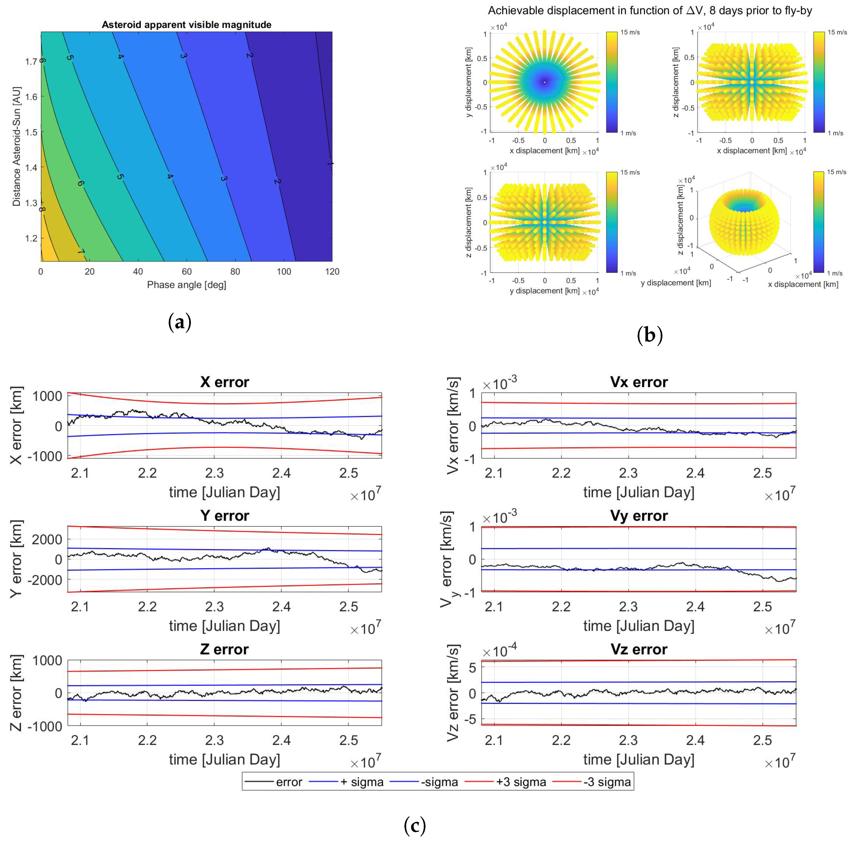
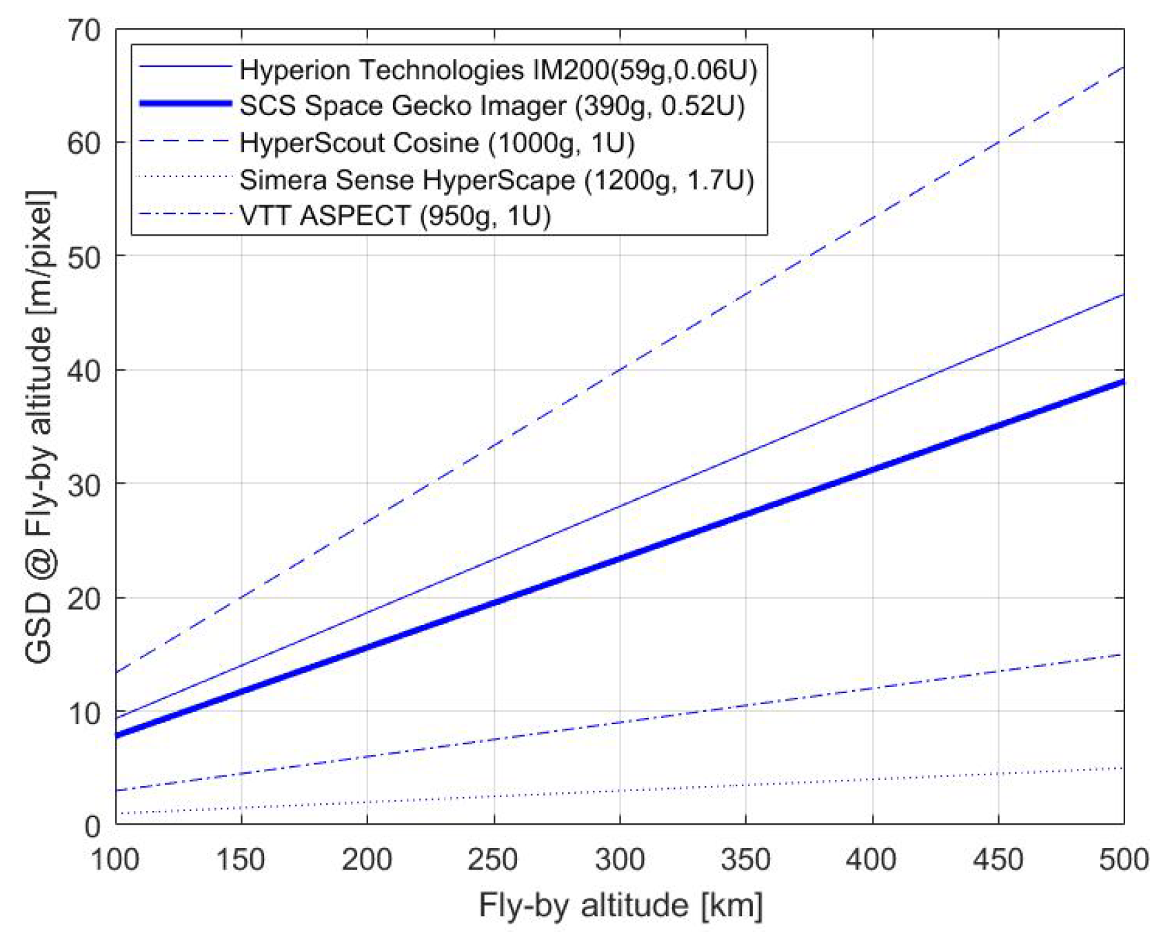
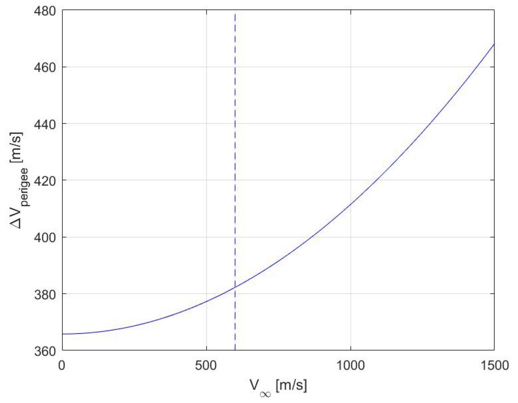
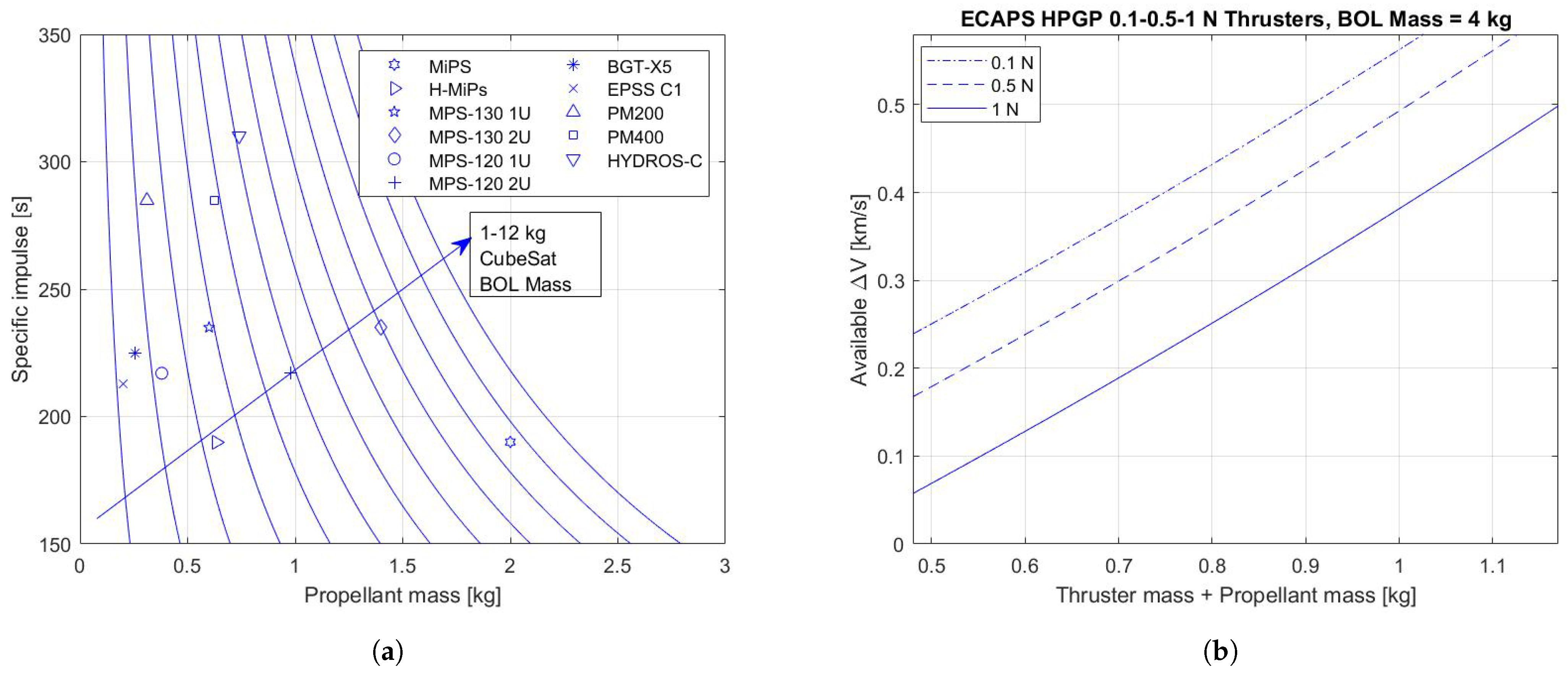
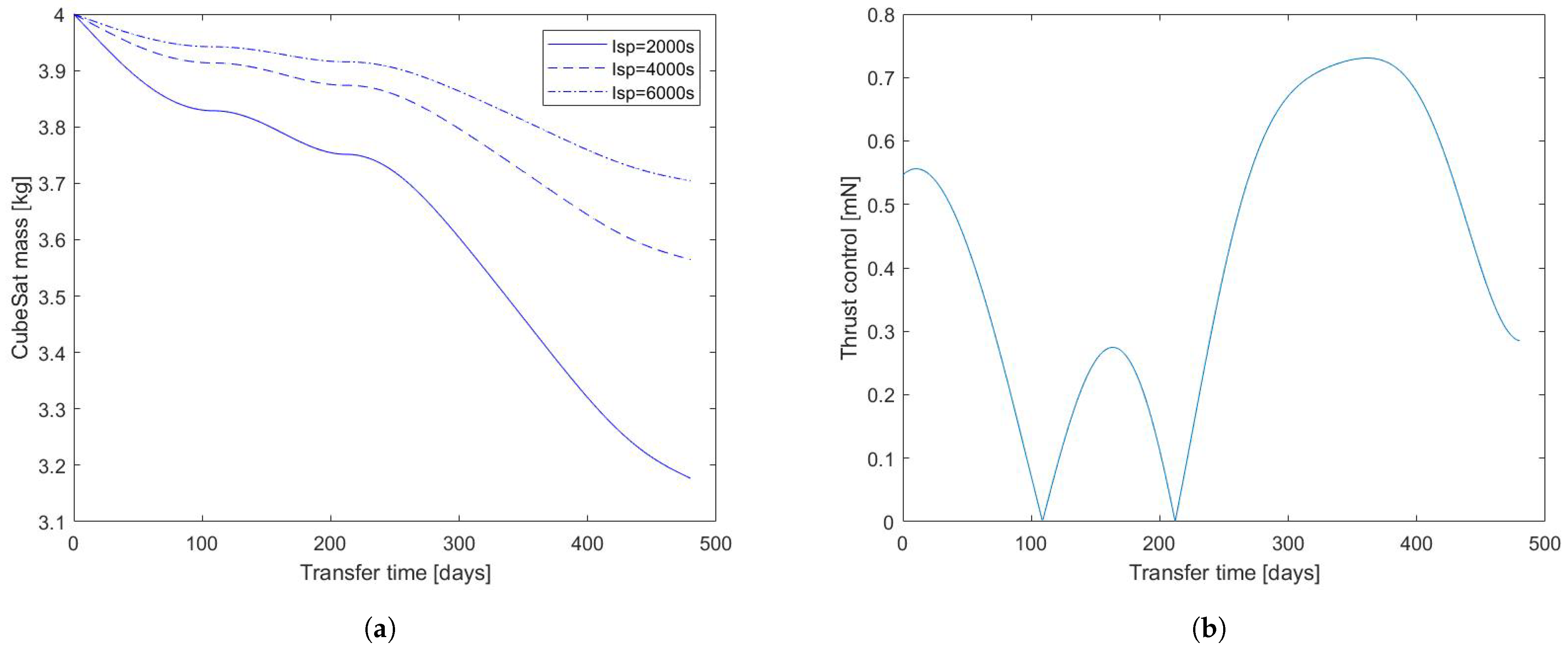
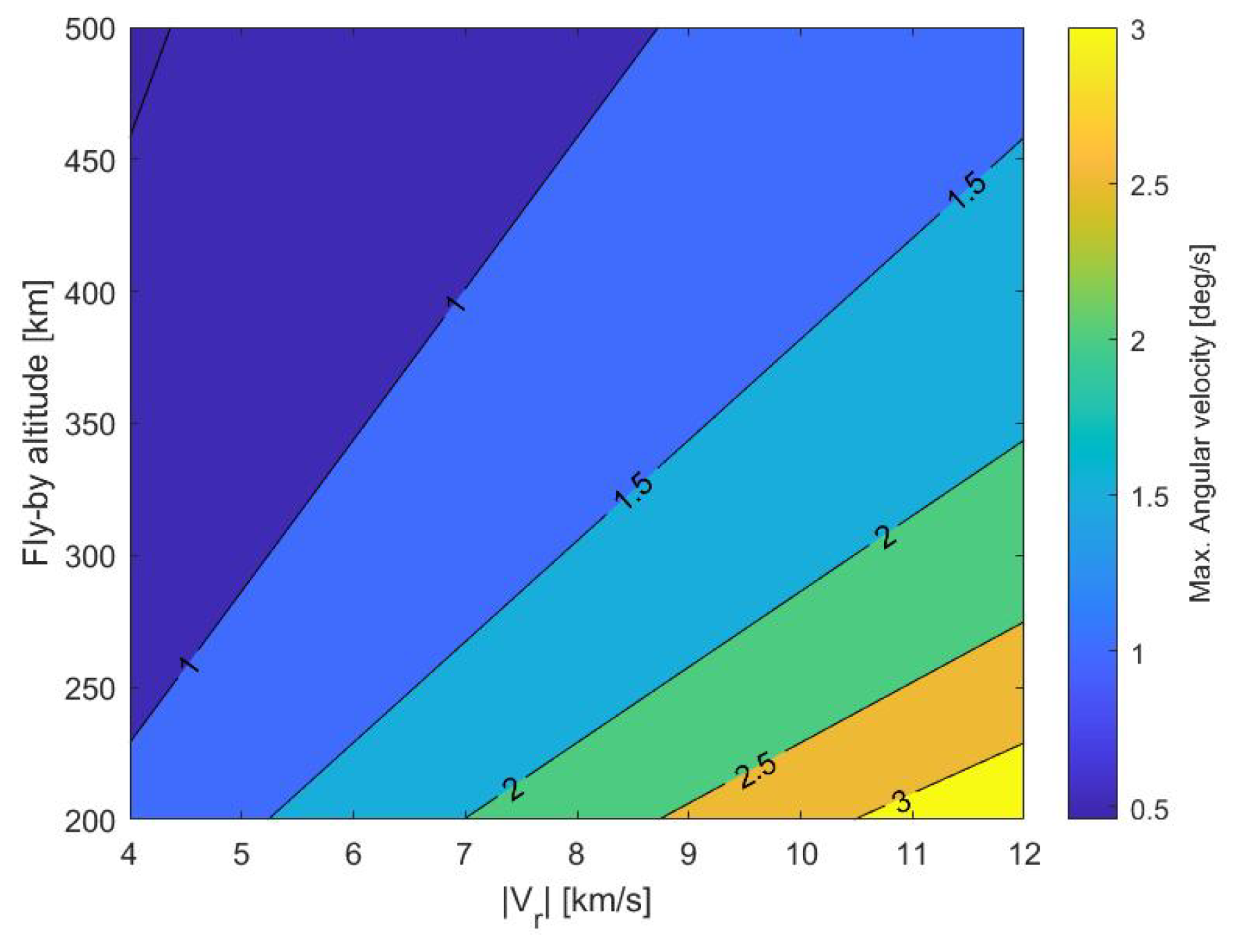
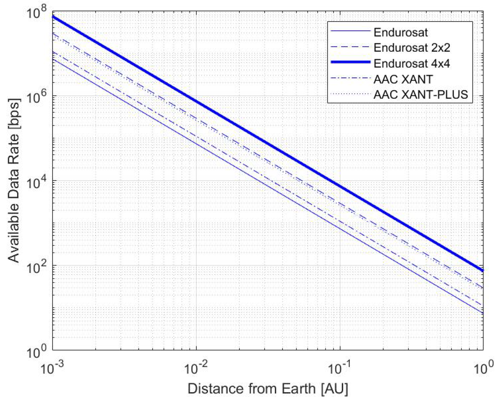
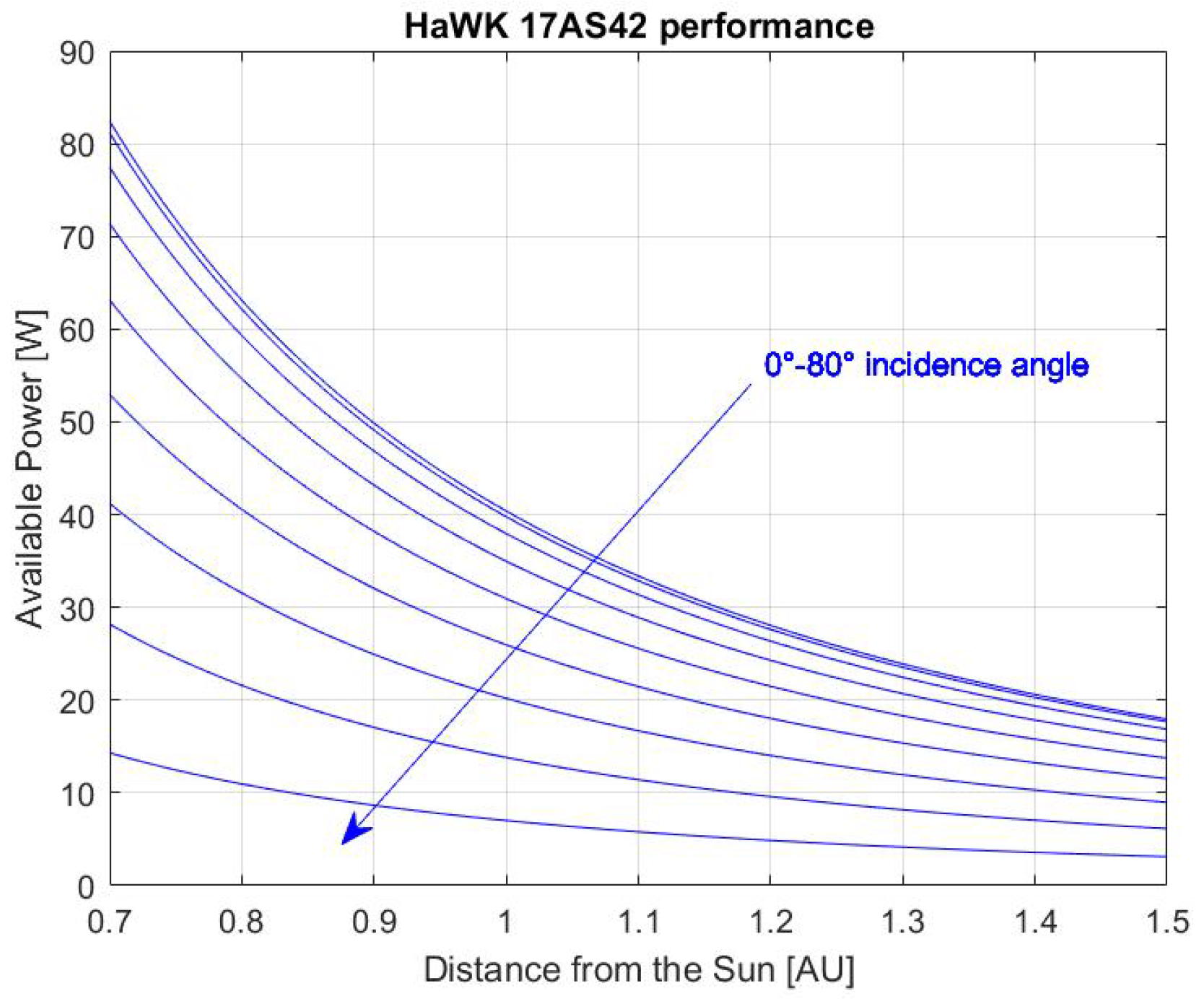
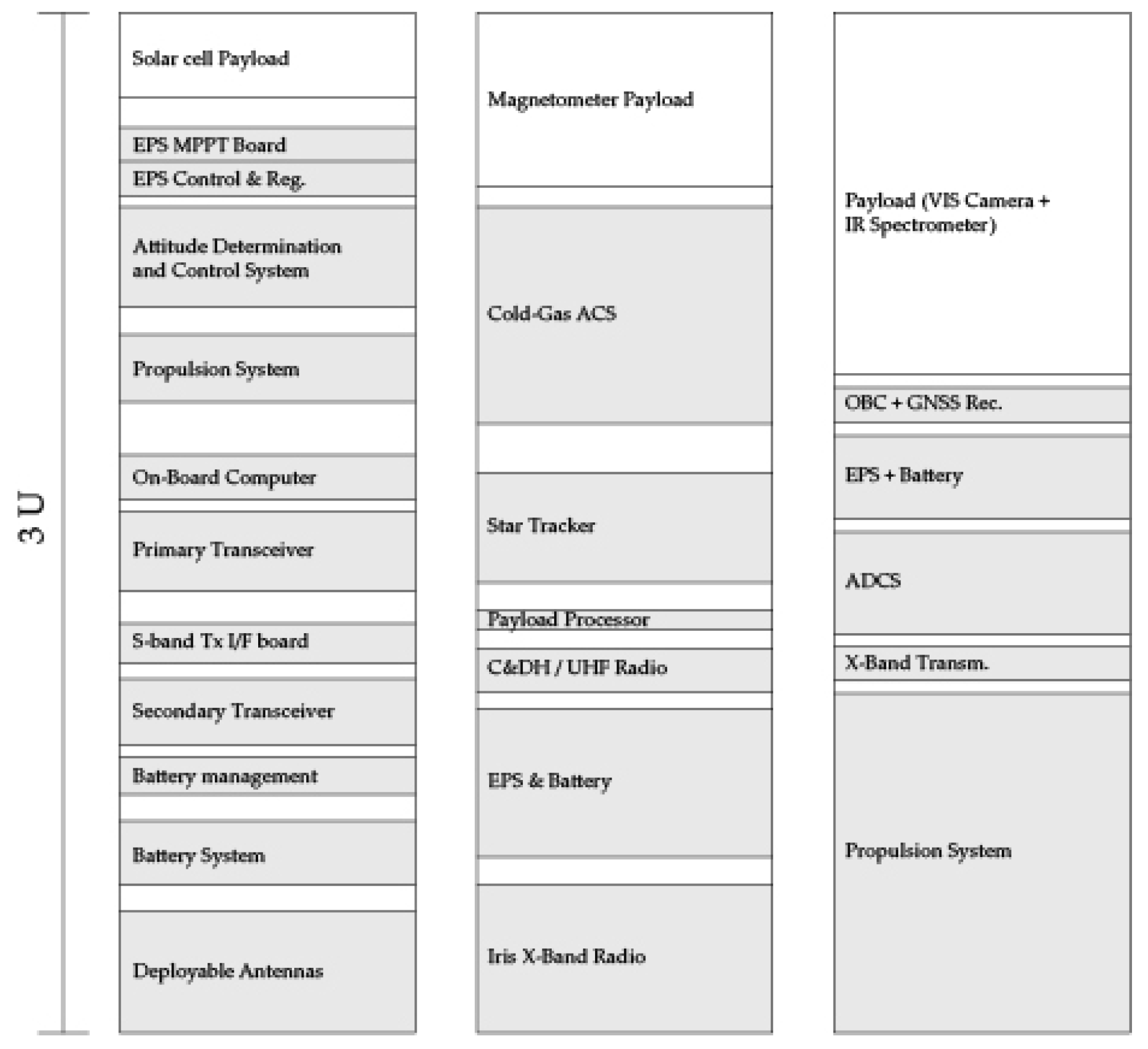
Table 1.
Mission Requirements definition.
| Acronym | Mission Requirement |
|---|---|
| MR1 | Total mass shall be below 4 kg |
| MR2 | Total volume shall fit 3U |
| MR3 | The spacecraft shall exploit fully-autonomous navigation strategy |
| MR4 | Mission duration shall not exceed 650 days |
| MR5 | The architecture shall exploit COTS components for all subsystems |
| MR6 | The spacecraft shall be equipped with payload in the visible and IR ranges |
| MR7 | The spacecraft shall be equipped with a propulsion system |
| MR8 | The spacecraft shall be equipped with primary and secondary power systems |
| MR9 | The spacecraft shall be equipped with communication system to downlink the scientific dataset |
Table 2.
Description of the mission phases.
| Phase | Acronym | Duration |
|---|---|---|
| Injection and De-Spinning | ID | ∼1 day |
| Earth’s Escape | EE | ∼3–10 days |
| Deep-Space Cruise | DSC | ∼200–550 days |
| Close Encounter | CE | ∼1–14 days |
| Scientific Acquisition | SA | ∼1–2 days |
| Data Transmission | DT | ∼2–3 days |
| Final Disposal | FD | ∼5–6 days |
Table 3.
Target NEAs characteristics.
| Target | Departure Date | ToF [Days] | [km/s] | Diameter [m] |
|---|---|---|---|---|
| 99942 Apophis | 6 August 2028 | 230 | 0.1 | 320 |
| 4660 Nereus | 18 May 2028 | 100 | 0.2 | 330 |
| 35107 | 14 January 2025 | 205 | 0.2 | 929 |
| 161989 Cacus | 17 December 2039 | 635 | 0.2 | 635 |
| 153201 | 1 July 2032 | 535 | 0.3 | 510 |
| 66391 Moshup | 1 February 2036 | 115 | 0.3 | 1317 |
| 13651 | 3 April 2029 | 815 | 0.4 | 562 |
| 7482 | 8 April 2031 | 640 | 0.4 | 1052 |
| 4034 Vishnu | 27 April 2033 | 510 | 0.4 | 420 |
| 142464 | 20 August 2034 | 625 | 0.5 | 886 |
| 138127 | 24 May 2027 | 260 | 0.5 | 754 |
| 65679 | 17 November 2036 | 615 | 0.5 | 918 |
| 1943 Anteros | 20 December 2025 | 165 | 0.5 | 2300 |
| 2102 Tantalus | 27 April 2034 | 635 | 0.5 | 1650 |
| 3200 Phaethon | 4 March 2028 | 985 | 0.6 | 300 |
| 11500 Tomaiyowit | 12 April 2035 | 235 | 0.6 | 738 |
Table 4.
Low-thrust analysis results.
| Target | Mp [g], Isp = 2000 s | Mp [g], Isp = 6000 s | ToF [Days] | Max. Thrust [mN] |
|---|---|---|---|---|
| 99942 Apophis | 650 | 210 | 560 | 0.62 |
| 4660 Nereus | 780 | 210 | 510 | 0.98 |
| 161989 Cacus | 1100 | 400 | 590 | 1.10 |
| 13651 | 900 | 270 | 590 | 0.70 |
| 7482 | 900 | 310 | 590 | 1.05 |
| 4034 Vishnu | 1400 | 450 | 530 | 1.60 |
| 65679 | 830 | 300 | 490 | 0.72 |
| 1943 Anteros | 520 | 190 | 490 | 0.52 |
| 2102 Tantalus | 850 | 300 | 480 | 1.00 |
| 11500 Tomaiyowit | 1100 | 400 | 580 | 1.05 |
Table 5.
Commercial-off-the-shelf (COTS) On-Board Computer (OBC) Characteristics.
| Producer | Product | CF [Mhz] | Vol. [U] | Mass [g] | PC [mW] | MS [Gb] |
|---|---|---|---|---|---|---|
| Endurosat | OBC [77] | 216 | 0.23 | 58 | 340 | 0.256 |
| AAC Clyde Space | KRYTEN-M3 [78] | 50 | 0.23 | 61.9 | 400 | 0.008 |
| AAC Clyde Space | S. OBC LEON3FT [79] | 50 | 0.17 | 130 | 1300 | 2 |
| AAC Clyde Space | S. TCM LEON3FT [80] | 50 | 0.17 | 134 | 1300 | 32 |
| InnoFlight | CFC-300 [81] | 767 | 0.14 | 120 | 1000 | 16–384 |
| Hyperion Technologies | CP400.85 [82] | 500 | 0.01 | 7 | 550 | 7.5–64 |
| GomSpace | NanoMind A3200 [83] | 64 | 0.02 | 24 | 170 | 0.160 |
| SatRevolution | Advanced OBC [84] | 216 | 0.08 | 52 | 1000 | 0.008 |
| ISIS | iOBC [85] | 400 | 0.12 | 100 | 400 | 4–32 |
Table 6.
Power budgets of mission phases, based on components datasheets.
| Phase | Subsystems | Nominal [mW] | Peak [mW] |
|---|---|---|---|
| ID | ADCS, Navigation | 1600 | 4600 |
| EE | ADCS, Navigation, Propulsion, OBDH | 2100 | 44,000 |
| DSC | ADCS, Navigation | 1400 | 4500 |
| CE | ADCS, Navigation, Propulsion, OBDH | 2700 | 45,000 |
| SA | ADCS, Navigation, Payload, OBDH | 4600 | 8500 |
| DT | ADCS, Navigation, Communication, OBDH | 17,000 | 23,000 |
| FD | ADCS, Navigation, Propulsion | 2700 | 45,000 |
Table 7.
Mass and volume budgets.
| Manufacturer | Component | Subsystem | Mass [g] | Volume [U] |
|---|---|---|---|---|
| Endurosat | 3U Structure | - | 285 | 3 |
| Aerojet Rocketdyne | MPS-130 1U | Propulsion | 1700 | 1 |
| GomSpace | P31u | 200 | Power | ∼0.18 |
| MMA Design | HaWK 17AS42 | Power | ∼300 | 3 (2D) × 2 |
| Hyperion Technologies | iADCS200 | ADCS | 400 | 0.3 |
| Hyperion Technologies | SS200 (x6) | ADCS | 18 | ∼0.007 |
| AAC Clyde Space | Pulsar Data | Communication | 130 | ∼0.1 |
| Endurosat | 4x4 Patch antenna | Communication | 53 | ∼0.07 |
| Hyperion Technologies | CP400.85 | OBDH | 7 | 0.01 |
| Hyperion Technologies | GNSS200 | Navigation | 3 | ∼0.001 |
| Total | - | 3076 | <2 | |
| on each component dry mass | - | 3220 | “ | |
| on total dry mass | - | 3483 | " | |
| Hyperion Technologies | IM200 | Payload | 59 | 0.063 |
| Thoth Technologies | Argus 2000 | Payload | 300 | ∼0.3 |
| Total | - | 3435 | <3 | |
| on each component dry mass | - | 3598 | “ | |
| on total dry mass | - | 3897 | “ |
Publisher’s Note: MDPI stays neutral with regard to jurisdictional claims in published maps and institutional affiliations. |
© 2020 by the authors. Licensee MDPI, Basel, Switzerland. This article is an open access article distributed under the terms and conditions of the Creative Commons Attribution (CC BY) license (http://creativecommons.org/licenses/by/4.0/).
Share and Cite
MDPI and ACS Style
Casini, S.; Fodde, I.; Monna, B.; Cervone, A.; Gill, E. Novel 3U Stand-Alone CubeSat Architecture for Autonomous Near Earth Asteroid Fly-By. Aerospace 2021, 8, 9. https://0-doi-org.brum.beds.ac.uk/10.3390/aerospace8010009
AMA Style
Casini S, Fodde I, Monna B, Cervone A, Gill E. Novel 3U Stand-Alone CubeSat Architecture for Autonomous Near Earth Asteroid Fly-By. Aerospace. 2021; 8(1):9. https://0-doi-org.brum.beds.ac.uk/10.3390/aerospace8010009
Chicago/Turabian StyleCasini, Stefano, Iosto Fodde, Bert Monna, Angelo Cervone, and Eberhard Gill. 2021. "Novel 3U Stand-Alone CubeSat Architecture for Autonomous Near Earth Asteroid Fly-By" Aerospace 8, no. 1: 9. https://0-doi-org.brum.beds.ac.uk/10.3390/aerospace8010009
Note that from the first issue of 2016, this journal uses article numbers instead of page numbers. See further details here.