1. Introduction
Air-tightness of aircraft plays a significant role in the service performance of airborne equipment, life safety of airborne personnel, and flight safety. Air-tightness detection has become one of the indispensable technologies for aircraft, which runs through the lifetime of aircraft, including the manufacturing, flight tests, and service process [
1,
2]. Air leakage is mainly caused by the halfway assembling and sealing of the skin, hatch, skylight, and other parts. Although leakage is inevitable and allowable to the aircraft, excessive leakage will bring a heavy burden to the air supply system and pressure control system of aircraft [
3,
4]. Generally, the air-leakage detection for the unclosed components is always carried out in the final assembly of aircraft. The complicated process usually consumes time and energy with poor efficiency. Therefore, a suitable detection method for the air-leakage of unclosed components is essential to develop and is implemented to reduce time, energy, and difficulties in the final assembly.
Over the years, many gas leakage detection methods have been developed. Murvay et al. [
5] made an excellent survey on gas leakage detection and localization techniques. The author highlighted the pros and cons employing each leak detection solution, in which, the available leak detection techniques were classified into three categories (hardware-based, non-technical, and software-based methods) and twelve subclasses, such as acoustic, optical, cable sensor, and vapor sampling methods and so on. Wang et al. [
6] also gave a comprehensive overview of the research progress of new gas leak detection methods. The history and development of gas leak detection methods were described through three aspects of leakage detection, such as leakage judgment, leakage localization, and leakage rate determination. The technology of ultrasonic and infrared detections that have appeared in recent years was also explained in detail. In addition, Bansal et al. [
7] developed a novel method to regulate the air-leakage area in a household ventilation system by fan pressurization. With this technique, the leakage area can be revealed by an assessment of the leakage volumetric flow–pressure relationship. Li et al. [
8] proposed a new method by extracting a single non-dispersive mode in leakage acoustic vibrations for refining leak detection in gas pipelines. The acoustic coupling among the in-pipe gas and the pipe wall was examined to govern a dominant transmission path, and then the dispersive features and modal distributions of acoustic vibrations at dissimilar directions in the dominant transmission path were evaluated using guided wave theory.
The above-mentioned techniques are widely used for gas pipelines, and some of them have been used in sensor manufacturing and computing power. For the aircraft components, the available techniques are pressure-drop analysis, fuzzy-adaptive methods, mass spectrum detection [
9,
10,
11,
12,
13], infrared imaging analysis, bubble detection, showering test, acoustic analysis, halide effect analysis, and ultrasonic detection. However, most of the methods are used for the sealed parts or products, and less or no work has been done to detect the air-leakage of unclosed components at the stage of part assembly. For large aircraft, it is an inevitable requirement to develop an efficient method for air-leakage detection during the period of the part assembly to reduce time, energy, and cost. Therefore, based on the principle of ultrasonic generation in negative pressure conditions, an ultrasonic-based detection method and experimental apparatus/experimental setup has been proposed and designed to detect the air-leakage of unclosed components for the aircraft. The relationship between the acoustic power, sound pressure, and the leak aperture and detection distance is set up. Moreover, the model of leakage rate, aperture, and system pressure has been established. Finally, verifications are carried out. The method proposed in this paper can be used to detect the air-leakage of unclosed components of the aircraft, such as the subassembly of the wing, hatch, skin, skylight, and air-tight end frame. Furthermore, it is expected to be applied before the final assembly, and to reduce the testing time, energy consumption, and cost for the air-leakage detection in the final assembly stage of large aircraft.
2. Materials and Methods
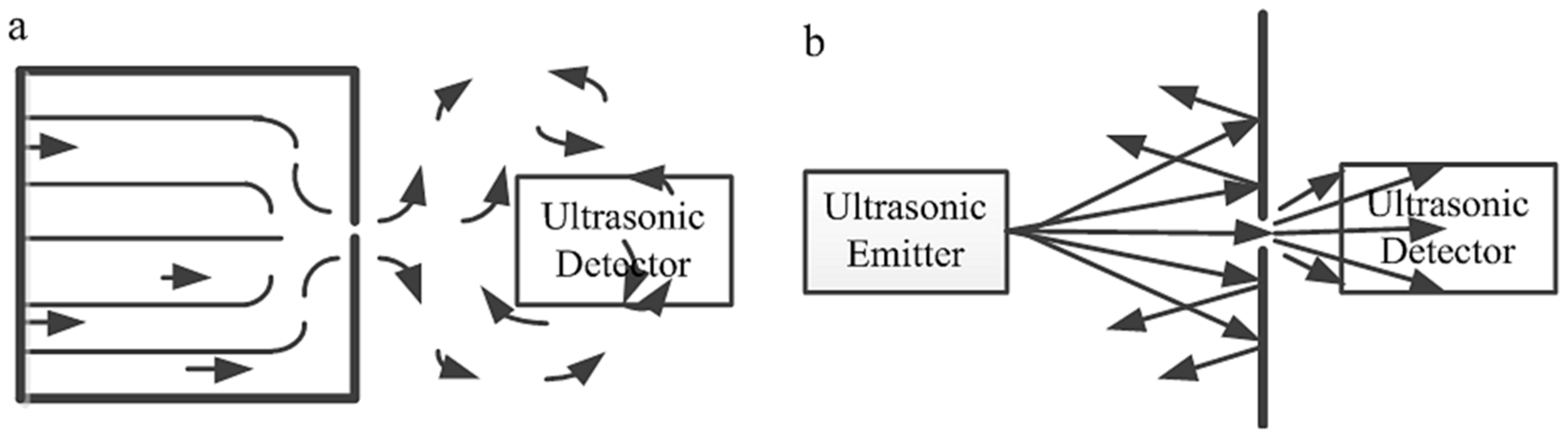
There are two kinds of ultrasonic-based detection of air-leakage as shown in
Figure 1 [
14]. The first one uses an ultrasonic detector outside of the container, and the ultrasonic signal is detected when the high-pressure air is flowing out through the small leak aperture (
Figure 1a). The second method is using an ultrasonic detector beside the unclosed component to measure the ultrasonic signal, which is emitted by an ultrasonic emitter on the other side of the component (
Figure 1b).
Regarding the former method, when the pressure difference between the inside and outside of the sealed container is high enough for a leak aperture, a turbulent airflow appears near the leak aperture, which will generate sound waves with certain frequencies near the leaks. There is a close relationship between the frequency and the cross-section area under certain pressure conditions. Usually, the acoustic frequencies are less than 20 kHz and the sound can be heard by ears when the cross-section area is large. If the cross-section area is small enough, certain bands of the acoustic frequencies will be higher than 20 kHz, which can be captured by the ultrasonic detector [
15]. This method is only suitable for the sealed parts because it is very difficult to construct a sealed cavity with high-pressured gas for the unclosed components. Later, the method is suitable for the unclosed thick components; meanwhile, an extra ultrasonic emitter should be equipped. Based on the above ultrasonic detection methods, an ultrasonic-based detection method for the air-leakage has been proposed with a combination of negative pressure difference analysis and ultrasonic detection method. The principle is similar to that of the former method with different construction, which will be described in
Section 2.2.
2.1. Design of the Ultrasonic-Based Detection System
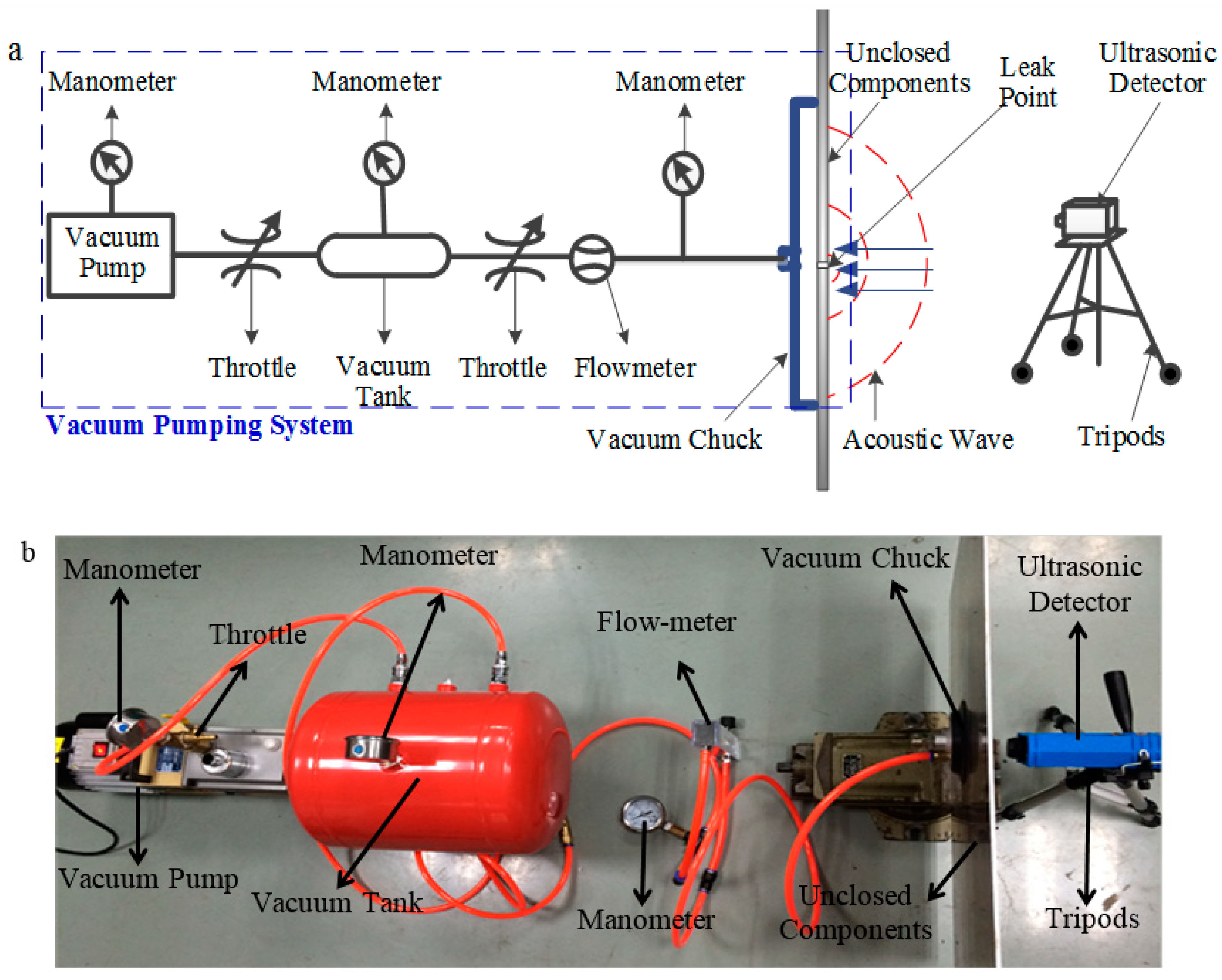
The ultrasonic-based detection system for the unclosed components is shown in
Figure 2.
Figure 2a depicts the design of a cylindrical shell depicting the system. The system consists of a 2XZ-4 vacuum pump with an air-exhausting rate of 4.0 L/s, three YZ-60 manometers with a measuring range of 0.01~0.1 MPa, a 20L vacuum tank with a counter size of 350 mm × 280 mm × 370 mm, and an LZB-6 flow-meter with a measuring range of 0.6~6 m
3/h and an SDT270 ultrasonic detector. A 500 mm × 500 mm × 3 mm dimensions of 2024 aluminum plate is selected as the test sample to simulate the unclosed component, on which several leaks (holes) with different diameters are machined by wire-cut electrical discharge machining (WEDM).
To obtain a high pressure-drop (negative pressure) condition, a vacuum cavity is constructed with the help of the vacuum pumping system. When the system works, the vacuum chuck can be absorbed tightly to the unclosed component, and a negative pressure condition can be obtained. If the leak aperture exists in the absorbing area, the ambient air will flow into the vacuum cavity. Otherwise, the ultrasonic wave will be generated near the leak point, which can be captured by the ultrasonic detector on the other side of the unclosed component. This system is suitable for unclosed components with complex shapes due to the flexibility of the rubber vacuum chuck. Different types of formation controls are practiced—obstacle detection, commonly.
The generation of ultrasonic caused by air-leakage is affected by a variety of factors. Among these, three factors, such as detection distance r, system pressure (pressure of the vacuum cavity) pt, and leak apertured, are the most important ones [
16,
17,
18,
19]. In this setup, the ultrasonic detector is fixed on an adjustable tripod with a variation of detection distance r, a throttle is used to control the system pressure pt. Besides, leak apertures with different dimensions are machined by WEDM before the experiments.
2.2. Acoustic Signal and Leakage Rate Models
The system pressure
pt can be assumed as a constant parameter due to the short detection process. Under a certain length of the leak
l which is equal to the thickness of the unclosed component, the relationship between the acoustic power
PT and other variables are expressed in Equation (1), which is developed from the relative equation in [
20].
where
ρ0 is the density of ambient air (air density in the high-pressure area),
ρs is air density in the vacuum cavity (air density in negative pressure area),
c0 is the velocity of acoustic wave propagation,
pout is atmospheric pressure outside of the vacuum cavity. Additionally,
γ =
cp/
cv, where
cp and
cv are specific heat at constant pressure and specific heat at constant volume of the ambient air, respectively.
For the unclosed components, pout/ρ0, (pt/pout)ρ0 and l can be regarded as constants due to the short detection process. Therefore, the acoustic power PT is a function that depends on the leak aperture ‘d’. The d can be calculated when the PT is measured.
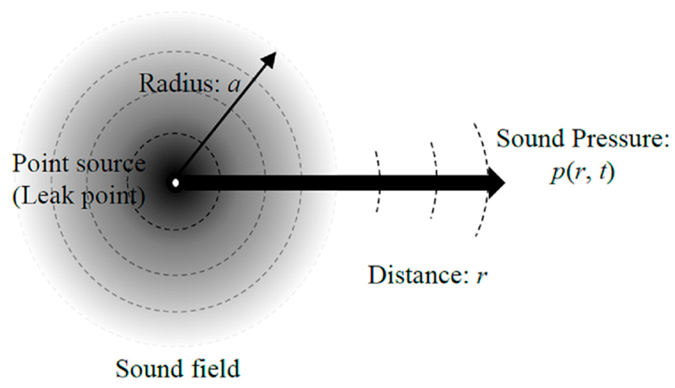
The acoustic signal generated at the leak of the unclosed component can be captured only when it is transmitted to the ultrasonic detector. Assuming the sound source at the leak is a point source, the transmission of the sound field can be expressed as shown in
Figure 3. Thus, the acoustic wave equation of the point source sound field and its solution are deduced as Equations (2) and (3), respectively.
where
pA=|
A|/
r is the amplitude of sound pressure in the sound field,
θ is the phase,
ω is the angular frequency of the phase,
k is the propagation coefficient. The sound intensity at the position
Ir, and a distance
r from the ultrasonic detector to the point source, are shown in Equation (4). If the leak point is on the normal of the ultrasonic detector’s receiving point, the sound pressure captured by the ultrasonic detector can be expressed as Equation (5).
From Equation (5), it can be found that if the leak length l and the detection distance r are given, the leak aperture ‘d’ can be calculated when the PT has already been measured.
Leakage Rate Model
Assuming the air in the vacuum pump system is in an ideal state, i.e., the airflow in the pipeline and leak is an isentropic flow which satisfies the adiabatic reversible process. Additionally, assuming the air velocity in the pipeline and leak is much greater than that in the vacuum chuck, and the energy loss caused by friction and heat exchange between the air and the outside environment is very small. The airflow velocity at the inlet of the flow-meter is calculated using Equation (6). The leakage rate
Q is calculated using Equation (7) [
21].
where
A is the cross-section area of the inlet of the flow-meter (leakage area). It can be seen from Equation (7) that the leakage rate
Q will decrease with the increase of system pressure
pt, and the leakage rate
Q can be calculated with the help of the measurement result of the
pt. In the actual measurements, the flow-meter is re-calibrated owing to the change of medium and measurement state (Equation (8)).
where
Q1,
P1, and
T1 are the leakage rate, absolute pressure, and absolute temperature of the air in an ideal state and to be incompressible. When the air velocity in the pipeline and leak is much greater than that in the vacuum chuck, and the energy loss caused by friction and heat exchange between the air and the outside environment is very small, and thus the energy loss can be negligible. While,
Q2,
P2, and
T2 are the leakage rate, absolute pressure, and absolute temperature of the air in the real experimental state, respectively.
The flow-meter is located inside the system, and the internal flow rate of the system can be measured on-line, but there is a little bit of difference, to that at the leak. The vacuum system pipe is similar to the gas pipeline system connected by several different diameters. Thus, Bernoulli’s equation is used to calculate the real leakage rate, and from the relationship between the leakage rate and the leak aperture, pressure can be obtained. Assuming that the flow-meter is located at the position of the pipe
Section 1, the leak is taken as that at position 2, then the Bernoulli equation (Equation (9)) is shown as follows.
where
P1,
ρ1,
v1, and
h1 are the air pressure, density, speed, and absolute height at the inlet of the flow-meter, and
P2,
ρ2,
v2, and
h2 are the air pressure, density, speed, and absolute height at the leak respectively. In the experiments, the height of the flow-meter inlet is equal to that of the leak, and the air pressure is approximately constant in the whole system, then it can be considered that
P1 =
P2,
ρ1 =
ρ2,
v1 =
v2 and
h1 =
h2. In the leak-detection process, the vacuum tank can keep working to provide a relative stable system pressure
pt. Therefore, Equation (9) can be applied for the whole leak-detection process. Besides, using the equation
Q = Av, Equation (10) can be deduced.
2.3. Experimental Setting
Based on the theoretical analysis, single-factor experiments of the detection distance
r, leak aperture ‘
d’, and system pressure
pt on the sound pressure
prs and leakage rate
Q are undertaken in this study. All the experiments are carried out on the ultrasonic-based detection system for unclosed components (
Figure 2). The experimental parameters are shown in
Table 1.
3. Results
3.1. Effects of Detection Distance and Leak Aperture on Sound Pressure
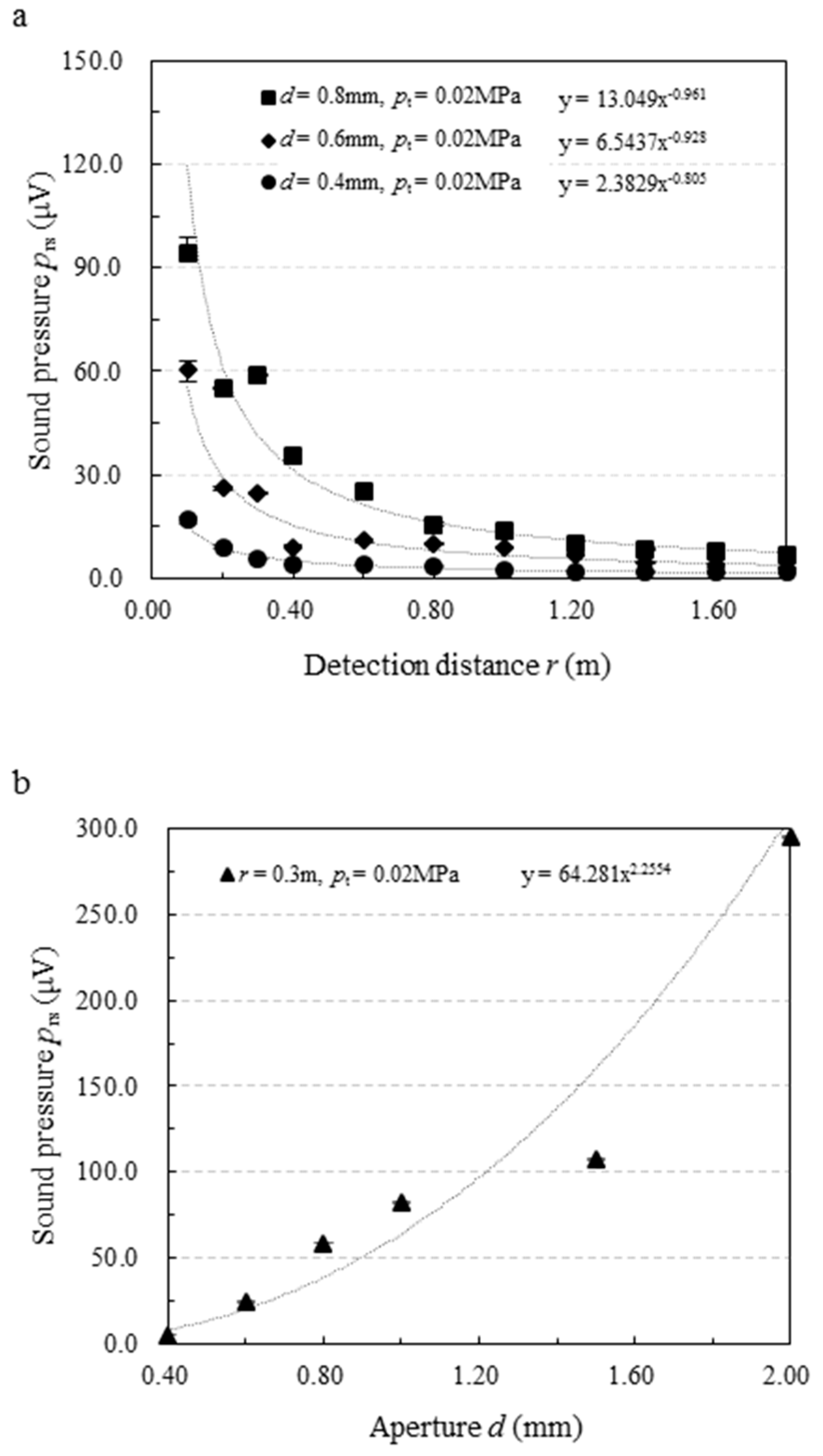
Figure 4a shows the effect of detection distance on the sound pressure. The sound pressure measured by the ultrasonic detector decreases sharply when r ≤ 0.6 m, and decreases smoothly when r > 0.6 m with the increase of detection distance. Its variation trend is in agreement with the analysis to Equation (5). For example, the relationships between the sound pressure and the detection distance at the leak aperture
r = 0.8 m and 0.6 m confirmed the laws of
prs ∝
r-0.961 and
prs ∝
r-0.928, respectively. They are closer to the relationship denoted in Equation (5),
prs ∝
r-1. However, a slight difference exists because of the absorption and scattering of a certain amount of ultrasonic in the ambient air, which is not considered in Equation (5). As the experiment results at
r = 0.4 m, the relationship between the sound pressure and the detection distance is
prs ∝
r-0.805, which decays more slowly than
prs ∝
r-1. It may result from the turbulence/flow separation and even compressible effects in the neighborhood of the leak. Besides, as the detection distance exceeds 0.8 m, the measured value reduces to a very low level, and the difference among the sound pressure at
d = 0.4 mm, 0.6 mm, and 0.8 mm becomes smaller and smaller, which will increase the difficulty of determination on the leak aperture size. Therefore, the suggested detection distance is ≤ 0.8 m.
In
Figure 4b, the effect of the leak aperture on the sound pressure is highlighted. A sudden increase in sound pressure was observed with the increases of the leak aperture. Its variation trend is also in agreement with the analysis to Equation (5), i.e.,
prs ∝
dc. However, the index
c obtained from the experiment is 2.2554 (as shown in the fitting formula in
Figure 4b), which is less than that of
c = 4 denoted in Equation (5). It means the theoretical equation, Equation (5), should be corrected according to the experiment because the absorption and scattering of a certain amount of ultrasonic in the ambient air are not considered in it. Additionally, it can be seen from both
Figure 4a,b that the measured value of sound pressure is very low when the leak aperture is 0.4 mm. If the leak aperture is less than 0.4 mm, it will increase the detection difficulty because of the unavoidable noise jamming in the workshop of the assembly when the detection method is put into engineering application. Thus, the suggested minimum leak aperture for the developed detection system is 0.4 mm.
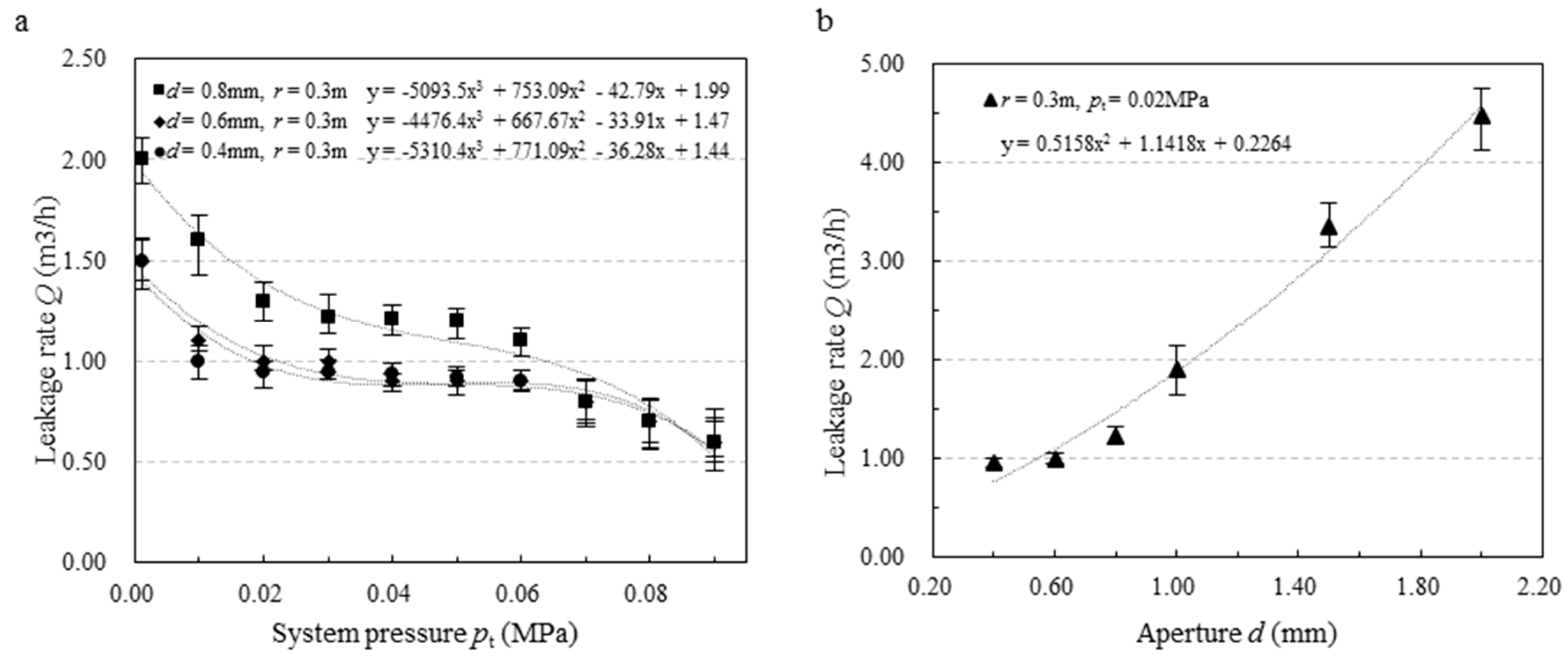
3.2. Effects of System Pressure and Leak Aperture on the Leakage Rate
The effect of system pressure on the leakage rate can be seen in
Figure 5a. The leakage rate decreases with the increase in system pressure. Its variation trend is in agreement with the analysis of Equation (7) to some extent. However, a clear difference can be found in that the leakage rate decreases sharply when the system pressure increases within the range of 0.001 MPa~0.02 MPa, approximately stable in the range of 0.02 MPa~0.06 MPa, and then decreases slightly in the range of 0.06 MPa~0.09 MPa. It indicates that any small fluctuation of the system pressure will add difficulty to the evaluation of the size of the leak aperture by detecting the leakage rate at a very high- or very low-pressure difference between inside and outside of the vacuum cavity. Therefore, the suggested system pressure for air-leakage detection is from 0.02 MPa to 0.06 MPa, i.e., the pressure difference is kept in the range of 0.04 MPa~0.08 MPa.
Figure 5b shows the effect of the leak aperture on the leakage rate. It can be found that the leakage increases sharply with the increase of leak aperture. Its variation trend confirms the analysis discussed in Equation (7). Therefore, in the process of air-leakage detection with an ultrasonic detector, the system pressure can be set to a certain stable value due to its slight influence on the leakage rate, and the size of the leak aperture can be computed directly by the leakage rate measured by the flow-meter.
4. Conclusions and Discussion
In this paper, an air-leakage detection method, which combines the ultrasonic detection with the negative pressure difference analysis, has been suggested for the unclosed components of aircraft. First, an ultrasonic-based air-leakage detection system is designed, then the acoustic signal model and leakage rate model are established to analyze the variation trend of the sound pressure and leakage rate with the change of detection distance, leak aperture, and system pressure. Finally, experiments are carried out to investigate the variation trend in detail. The main conclusions of the study are as follows:
The negative pressure difference can generate an ultrasonic wave at the small leak, which is easy to capture by using an ultrasonic detector. The pressure difference was found suitable to detect the air-leakage of the unclosed components.
The sound pressure of the ultrasonic waves caused by air-leakage with a sudden decrease by the increase of detection distance. The suggested detection distance i < 0.8 m.
The sound pressure increases with the increase of the leak aperture. However, it is very low when the leak aperture is less than or equal to 0.4 mm. Thus, the suggested minimum leak aperture for the proposed method is 0.4 mm.
A small fluctuation of the system pressure will add up the difficulty to evaluate the size of the leak aperture by detecting the leakage rate when the pressure difference between inside and outside of the vacuum cavity is very high (≥0.08 MPa) or very low (≤0.04 MPa).
The leakage rate rises sharply with the increase of leak aperture but keeps approximately stable with the increase of system pressure from 0.02 MPa to 0.06 MPa. Therefore, the size of the leak aperture can be easily calculated by detecting the leakage rate when the system pressure is kept in the range of 0.02 MPa~0.06 MPa.
In summary, the ultrasonic-based detection method developed in this paper is a suitable way to detect the air-leakage of the unclosed components in the stage of part assembly. It can acquire the leakage position, leak aperture, and leakage rate in an accurate and fast way, which will reduce significantly the testing time, energy consumption, and cost for the air-leakage detection in the final assembly of aircraft.
Author Contributions
Conceptualization, Y.L., and M.J.; methodology, Y.L.; software, P.M.; validation, Y.L., N.H. and M.K.G.; formal analysis, A.M.K. and D.Y.P.; investigation, Y.L. and M.K.G.; resources, N.H.; data curation, Y.L. and P.M.; writing—original draft preparation, Y.L. and A.M.K.; writing—review and editing, revision, language editing, A.M.K. and M.J.; visualization, M.J. and D.Y.P.; supervision, N.H.; project administration, N.H.; funding acquisition, N.H. All authors have read and agreed to the published version of the manuscript.
Funding
This research was partially supported by the National Natural Science Foundation of China, grant number 51975289.
Data Availability Statement
Data not yet available public.
Conflicts of Interest
The authors declare no conflict of interest.
References
- Chen, P.Z.; Liu, Z.E.; Shi, Y.W. A design of the air-tightness detection system for large aircraft. In Proceedings of the 3rd High-Level Forum on the Development Strategy of Experiment & Measurement Technology in National Defense Science & Technology Industry, Beijing, China, 1 October 2010; pp. 346–350. [Google Scholar]
- Xu, X.Z.; Li, S.Q. Property analysis and application of large aircraft integral fuel tank sealant. Adv. Aeronaut. Sci. Eng. 2015, 6, 372–376. [Google Scholar]
- Li, J.J.; Wang, H.W.; Wang, J.S. The selection of leak detection methods for the aircraft gas system using fuzzy comprehensive evaluation. Aircr. Des. 2011, 31, 76–80. [Google Scholar]
- Shen, Y.L.; Wang, J.P.; Cao, K.Q. Analysis of the capability of the plane cabin pressure control system. Mach. Tool Hydraul. 2005, 11, 77–78. [Google Scholar]
- Murvay, P.S.; Silea, I. A survey on gas leak detection and localization techniques. J. Loss Prev. Process. Ind. 2012, 25, 966–973. [Google Scholar] [CrossRef]
- Wang, T.; Wang, D.Y.; Fan, W. The research progress of new gas leak detection method. Chin. Hydraul. Pneum. 2015, 15, 1–11. [Google Scholar]
- Bansal, P.; Mohabir, A.; Miller, W. A novel method to determine air leakage in heat pump clothes dryers. Energy 2016, 96, 1–7. [Google Scholar] [CrossRef] [Green Version]
- Li, S.; Cheng, N.; Wang, P.; Yan, D.; Wang, P.; Li, Y.; Zhao, X.; Wang, P. Extraction of single non-dispersive mode in leakage acoustic vibrations for improving leak detection in gas pipelines. J. Loss Prev. Process. Ind. 2016, 41, 77–86. [Google Scholar] [CrossRef]
- Xinfa, Y.; Rongxin, Y.; Liang, Z.; Xiaopeng, H.; Lichen, S. Infrared imaging leak testing for spacecraft. Spacecr. Environ. Eng. 2012, 29, 220–226. [Google Scholar]
- Xu, G.K. Realization and security of aviation product seal for advanced leak testing technology. Aeronaut. Manuf. Technol. 2013, 5, 103–108. [Google Scholar]
- Hu, J.W.; Zheng, B.Y.; Wang, C.; Zhao, C.H.; Hou, X.L.; Pan, Q.; Xu, Z. A survey on multi-sensor fusion based obstacle detection for intelligent ground vehicles in off-road environments. Front. Inf. Technol. Electron. Eng. 2020, 21, 675–692. [Google Scholar] [CrossRef]
- Yan, R.X.; Qi, L. The gas leak detection technology of the spacecraft on orbit based on acoustic sensor array. Phys. Procedia 2015, 70, 384–387. [Google Scholar]
- Yin, D.W.; Lin, J. Research on discrimination and denoising of weak gas leakage in aircraft air-tightness system. Open Cybern. Syst. J. 2015, 9, 2519–2525. [Google Scholar]
- General Editorial Board Editor. Aeronautical Manufacturing Engineering Handbook (Process Testing), 1st ed.; Aviation Industry Press: Beijing, China, 1993; pp. 580–592. [Google Scholar]
- Han, H.L.; Wang, T.Y.; Li, J.J. The design of intelligent ultrasonic gas leak detection and analysis system. J. Chang. Univ. Sci. Technol. 2010, 33, 114–117. [Google Scholar]
- Moon, C.; Brown, W.C.; Mellen, S.; Lovelace, D. Ultrasound techniques for leak detection in vehicle and pressure vessel production Lines. Soc. Personal. Psychol. Compass 2008, 3, 447–474. [Google Scholar]
- Sheen, S.H.; Chien, H.T.; Raptis, A.C. Ultrasonic techniques for detecting helium leaks. Sens. Actuators B Chem. 2000, 71, 197–202. [Google Scholar] [CrossRef]
- Yan, R.X.; Sun, W.; Li, W.D. Research and design on a portable intravehicular ultrasonic leak detector for manned spacecraft. Chin. Space Sci. Technol. 2015, 32, 58–65. [Google Scholar]
- Hu, J.; Zhang, H.; Liu, L.; Zhu, X.; Pan, Q. Convergent Multiagent Formation Control with Collision Avoidance. IEEE Trans. Robot. 2020, 99, 1–14. [Google Scholar] [CrossRef]
- Zhang, Q. Pneumatic Acoustics, 1st ed.; National Defense Industry Press: Beijing, China, 2012; pp. 210–211. [Google Scholar]
- Jiang, Y.; Gong, Q.C.; Ye, Q.; Liu, C.L. The Theoretical analysis and experiments of using ultrasonic to inspect the leak amount. J. Shanghai Jiaotong Univ. 2006, 40, 224–226. [Google Scholar]
| Publisher’s Note: MDPI stays neutral with regard to jurisdictional claims in published maps and institutional affiliations. |
© 2021 by the authors. Licensee MDPI, Basel, Switzerland. This article is an open access article distributed under the terms and conditions of the Creative Commons Attribution (CC BY) license (http://creativecommons.org/licenses/by/4.0/).


 ,
, 


