
A Study on Thermal Buckling and Mode Jumping of Metallic and Composite Plates

Faculty of Aerospace Engineering, Delft University of Technology, 2629 HS Delft, The Netherlands
*
Author to whom correspondence should be addressed.
Aerospace 2021, 8(2), 56; https://0-doi-org.brum.beds.ac.uk/10.3390/aerospace8020056
Submission received: 29 December 2020
/
Revised: 16 February 2021
/
Accepted: 17 February 2021
/
Published: 21 February 2021
(This article belongs to the Special Issue Advances in Aerospace Sciences and Technology)
Abstract
:Composite plates in post-buckling regime can experience mode jumping in their buckling shape, suddenly increasing the number of half-waves. This phenomenon can be advantageous, because the shape change could be used for local morphing or structural adaptability in future aerospace structures. A study of this phenomenon under heating is here presented, combining numerical and experimental techniques. At first, a set of parametric analysis was conducted to identify composite panels that present a mode jump when heated. Three plates were selected, one in aluminum alloy , and two in composite material, with layup and . The plates were tested in a new test setup for thermal buckling based on low thermal expansion fixtures. The mode jumping was successfully obtained experimentally for both composite plates. Numerical simulations predicted the general trends for all plates, and the mode jumps for the composite plates.
1. Introduction
Thin-walled composite structures are present in a wide range of aerospace applications, where they are required to operate under extreme conditions. Good examples are high-speed aircraft, which must cope with combinations of thermal and mechanical loads, and satellites, which endure large cyclic temperature oscillations. Such loading conditions make these structures susceptible to buckling. This phenomenon has been largely considered as an undesirable event, due to the significant impact it has over the stiffness and the ability of a structure to carry load. The use of post-buckled states in structural design has been mainly limited, if used at all, as a contribution to increase the mass efficiency of a vehicle. In this respect, plate elements are perfect candidates for this use due to their well-known stable nonlinear behavior. Composite materials add versatility and expand the design space for the structural designer, because plate buckling and post-buckling behavior can be tailored by varying the laminate stacking orientation [1,2]. Also, their elastic behavior allows the structure to return unscathed to the original state once the load decreases.
New research tendencies are observing buckling from a different standpoint: buckled states are no longer ‘forbidden’, but rather an additional structural state that has properties on its own and can offer additional functionalities [3]. A new research direction uses buckling as a mechanism for shape adaptability or morphing: the load triggers a shape change without the need of any additional actuator. For instance, several authors explore the shape change through mechanically induced buckling: Vos et al. studied control actuation through post-buckled precompressed structural elements [4], and Runkel et al. [5] explored the change in torsional stiffness in a wingbox allowing buckling in one of its plate side elements. Changing the shape through heat has also been investigated: Eckstein et al. investigated the multi-stability in shell structures using temperature increments [6], and the use of thermal gradients in hybrid laminates [7].
In some situations buckled plates may experience a sudden change in buckling shape, also known as a mode jump. The topic of mode jumping or mode change has been approached in limited occasions: While the contributions to the field of simulation of composite materials are numerous, refs [8,9,10], the amount of papers tackling the subject are more scarce [11]. The phenomenon has been thoroughly investigated numerically and experimentally by Falzon and Hitchings [12] and Falzon and Cerini [13], who proved the suitability of nonlinear dynamic explicit procedures for the prediction of this phenomenon in uniaxially compressed composite panels, and proved the large energy release after a mode jump. In a similar fashion, even though significant contributions have been made in the experimentation of buckling in the last decade (Arbelo et al. [14,15], Bisagni et al. [16,17], or Labans et al. [18]), to the best knowledge of the authors there are no experimental studies in the field of mode jumping of heated composite plates. There is, however, an experimental study done by Ehrhardt [19] in heated metallic plates, who showed that alternative equilibrium paths were reached when an external perturbation was present.
In order to demonstrate the feasibility of mode jumping under heating as a means to obtain shape change, experimental studies become an essential milestone. A large part of available bibliography on tests in thermal buckling of plates and shells refer to high-speed applications. This is the case of Percy and Fields [20] and Thompson and Richards [21], who tested two identical hat stiffened flat plates made in titanium and titanium matrix composite under diverse combinations of heating and mechanical loads, contributing in this way to new design concepts in heated structures; Rakow and Waas [22] tested metallic foam sandwich plates using an oven, taking advantage of the differences in thermal expansion between fixture and specimen; and other authors such as Murphy et al. [23], Amabili et al. [24] or Thornton [25] performed experimental studies on buckling of heated metallic plates using diverse approaches and heating source types. Most of these tests address thermal buckling on metallic materials, and only just a few tests of carbon composite plates and shells are available in literature: Breivik and Hyer [26] tested curved composite panels under both mechanical and thermal loads, showing that temperature gradients found had a relatively small effect over the considered specimens, Fields et al. [27] performed a thermostructural tests on a titanium matrix composite panel presenting a novel experimental setup for combined loading, and Wu and Gürdal [28] performed heating tests on carbon composite, fiber steered panels, as a first step towards the application of fiber tailoring in heated aerospace structures. More recently, Xu et al. [29] tested the thermal buckling of a flat panel of carbon fiber-reinforced, silicon carbide ceramic matrix composite.
The goal of this research is to study the feasibility of a new morphing possibility in which shape changes are induced into structural composite plates by heating and without the contribution of any external actuator. This phenomenon can take advantage of post-buckling regime and the mode jumps at higher load levels. This could offer advantages and complement existent or future designs of high-speed aircraft, or also deployable structures in which low weight and multi-functionality are desirable.
A methodology for selecting laminates that present mode jumping in their nonlinear post-buckling regime is described and applied. As a result, two composite plates are selected and subsequently tested in a novel experimental setup. Prior to that, a preliminary test of an aluminum alloy plate is also performed. Results are presented in the form of deflection curves and out-of-plane deformation plots.
In particular in Section 2 the mode jumping phenomenon is explained in detail; while in Section 3 a methodology for selecting laminates that present mode jumping in their nonlinear post-buckling regime is described and applied, leading to the selection of two AS4/8552 composite plates for experimentation. In Section 4 a novel experimental setup for thermal buckling of plates is presented; and in Section 5 the results of a preliminary test on a plate made in 2024T3 aluminum alloy and of the tests on both composite plates are reported in the form of deflection curves and out-of-plane deformation plots. Finally, all findings of this investigation are summarized in the conclusions in Section 6.
2. Mode Jumping on Heated Composite Plates
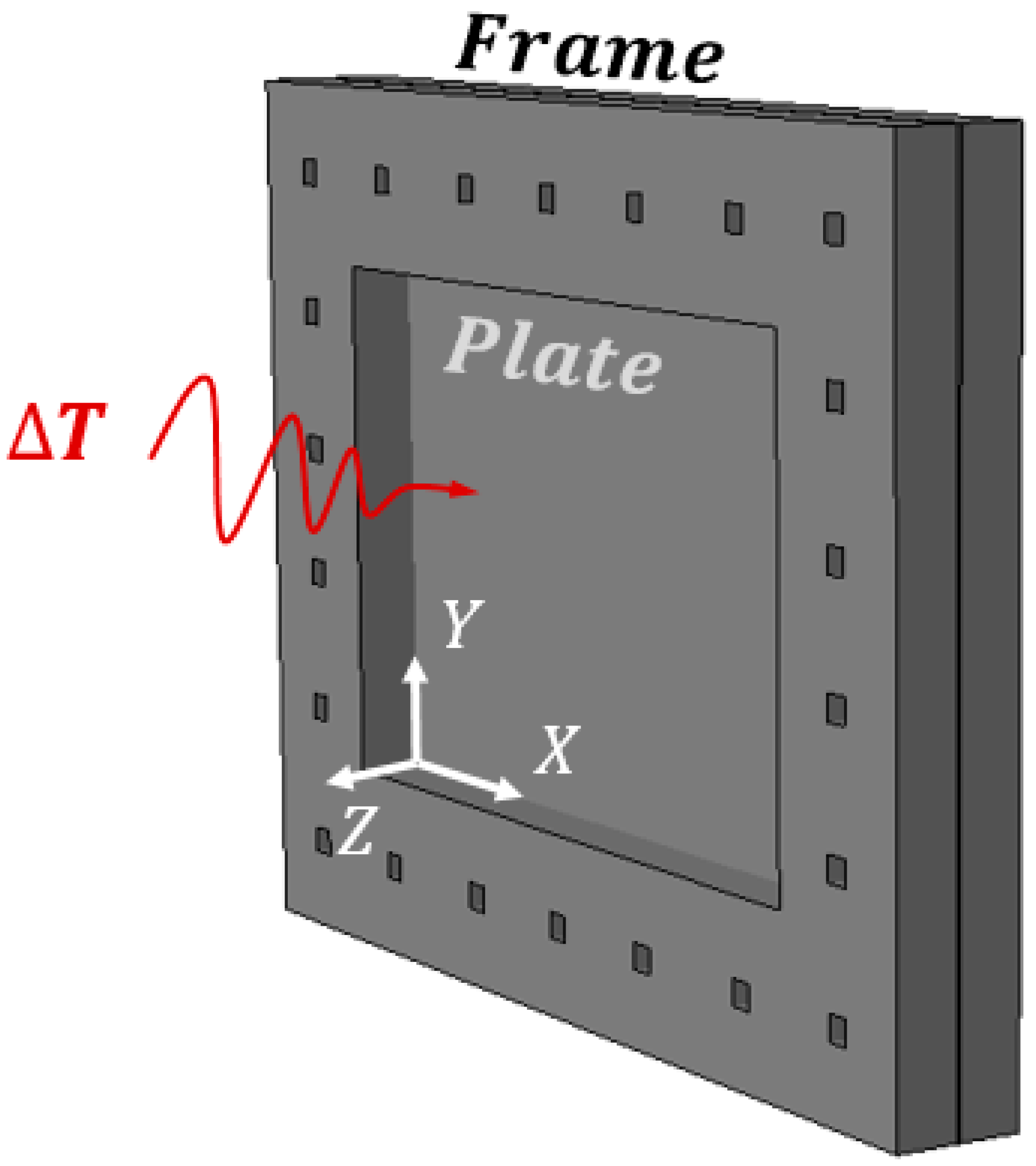
Mode jumping, also called mode switch or mode change, can be defined as a sudden variation in the post-buckled shape of a loaded panel, characterized by a fast switch from one buckling mode into another one [15]. In this study, mode changes caused by temperature increments are investigated. The studied phenomenon can be qualitatively described with the help of a generic flat plate, shown in Figure 1. The plate has length , width and thickness , and is located in a Cartesian system , with coordinates in plane with the mid-plane of the plate. In-plane size variations along , axis are constrained and rotations around plate edges are also constrained. The plate is subjected to a homogeneous temperature increment that is applied in a quasi-static manner.
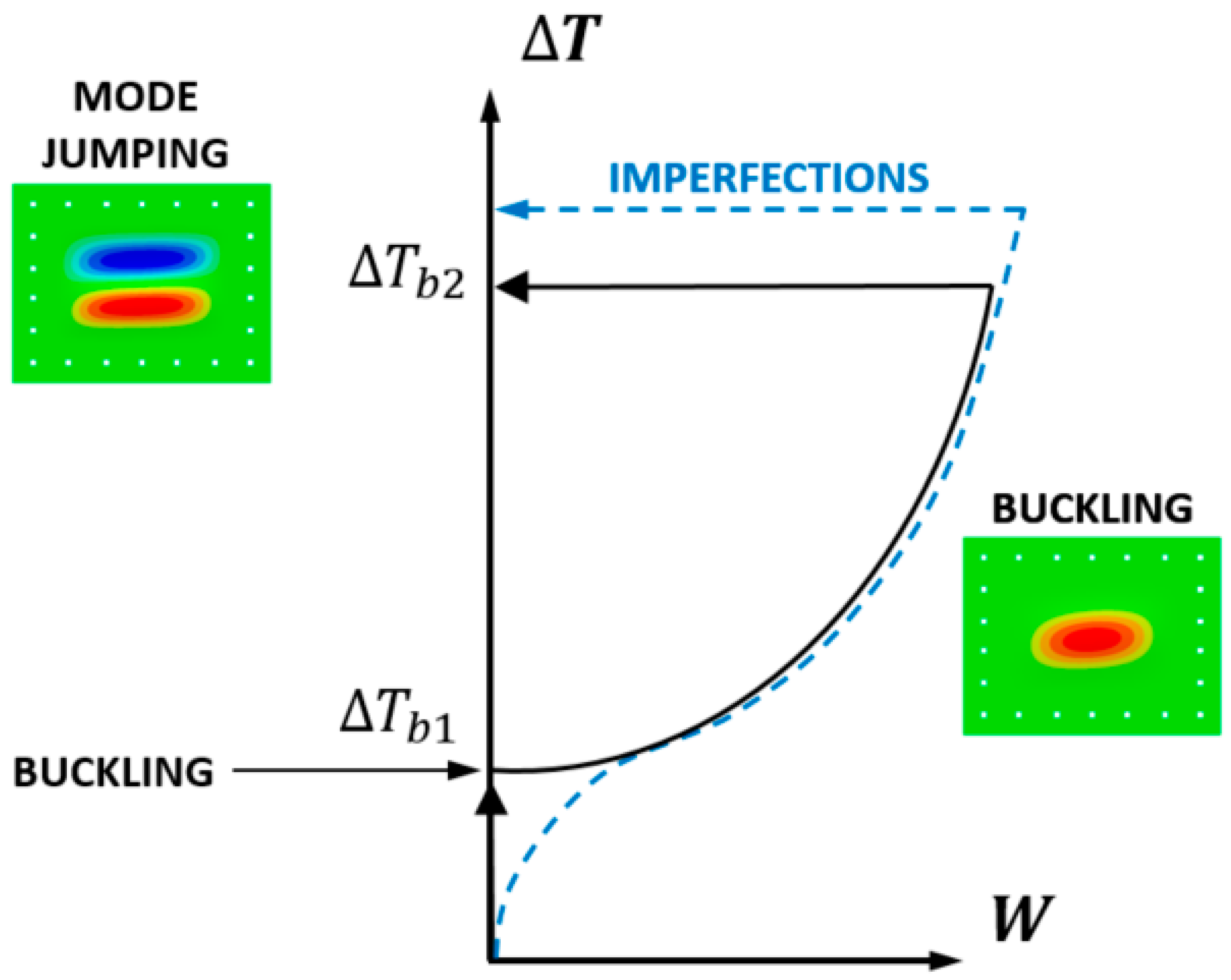
The response of the plate can be represented in a graph as reported in Figure 2, with temperature variation versus out-of-plane position of the point at the middle of the plate. Initially, the plate is considered to be at a stress-free state. Applying temperature increments , in-plane stresses arise as a consequence of restrained thermal expansion, and the plate starts to follow the equilibrium path reported as a bold black line. The plate, however, remains flat up until when its equilibrium path finds a bifurcation point. Temperature at this location is represented as , and is known as the first bifurcation temperature or also buckling temperature. For temperatures beyond this value the plate starts deforming out of plane, typically in a half-wave buckling shape. The plate is now in post-buckling state and therefore under non-linear behavior. If temperature keeps increasing, plates with some particular stacking orientation may experience a sudden change into a different, stable buckling shape. This event is commonly known as mode jumping. The temperature indicated as in the graph is known as mode jumping temperature, and the plate changes usually from a half-wave buckling configuration to two half-waves.
The described equilibrium path corresponds to a plate without imperfections. This is, however, an ideal case and in reality geometrical imperfections are always present. Due to this, the post-buckling behavior may differ from the ideal case. An example of a plate with initial geometric imperfections is also illustrated in Figure 2 reported as a blue dashed line. Depending on imperfection shape and amplitude, equilibrium path will vary, altering not only the nonlinear deflection path but also the mode jumping temperature . Additionally, other factors such as size variation due to expansion of the boundary conditions may have a significant impact in the nonlinear behaviour of the plate.
3. Analysis to Identify Composite Plates Presenting a Mode Jump under Heating
To select configurations of composite plates that achieve a mode jump under heating, three steps were conducted. First, a set of design requirements was established. Second, the design space was inspected for the existence of plates showing mode jumping through a parametric analysis in which both linear buckling and post-buckling behavior were examined. Third, the stacking orientations were improved by fine-tuning the layups.
In the first step, the design space was established by imposing geometry and layup constraints. A fixed plate size of compatible with the available oven was imposed. The plate was also required to have symmetric and balanced stacking orientation with a total number of 8 plies. The material [30], with properties reported in Table 1, was used for all analyses. This is a common carbon composite material which is not suitable for high temperatures, so a temperature limit of was imposed for the tests. As a consequence mode jumping temperature can never exceed this value.
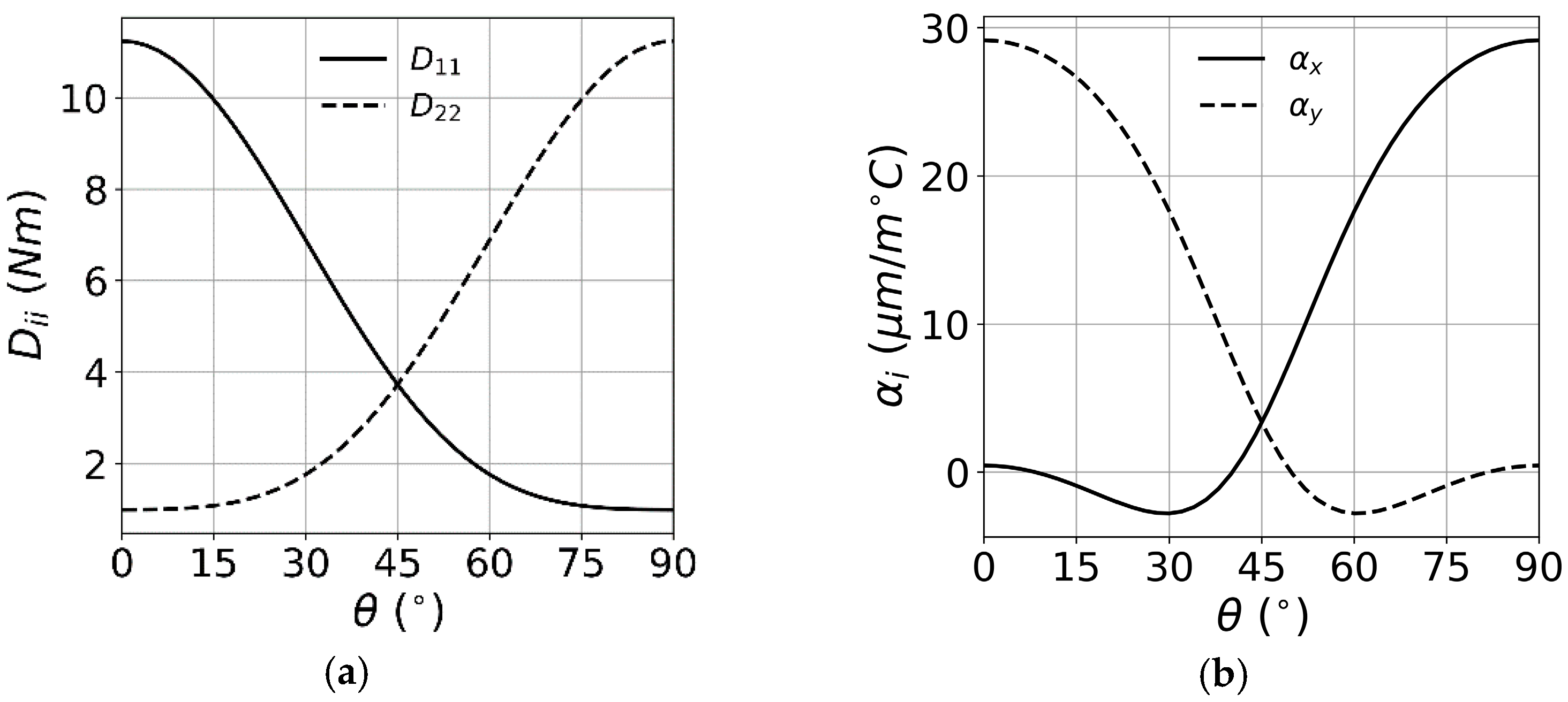
Assuming that in-plane plate size variations are perfectly constrained, the thermal buckling of a given composite laminated plate is governed by the laminate coefficients of thermal expansion (CTE) as well by the bending and membrane stiffness. Taking a generic angle-ply laminate , and using laminate theory, the variation of the bending stiffness components and , and the CTE and can be plotted versus the generic angle . These are reported in Figure 3a,b, respectively. It is possible to note that for small values of angle , the bending stiffness along axis is large, with its maximum at zero degrees, while CTE along direction is very low. Conversely, is minimized at , while is maximized. Thus, bending stiffness and thermal expansion show opposite trends, and a balance between these two factors must be achieved. In reality, boundary conditions will expand, stretching the plate and changing the buckling temperature. Due to this, the effect of boundary conditions was considered for the next steps in the laminate selection process taking into account the plate frame in the analyses.
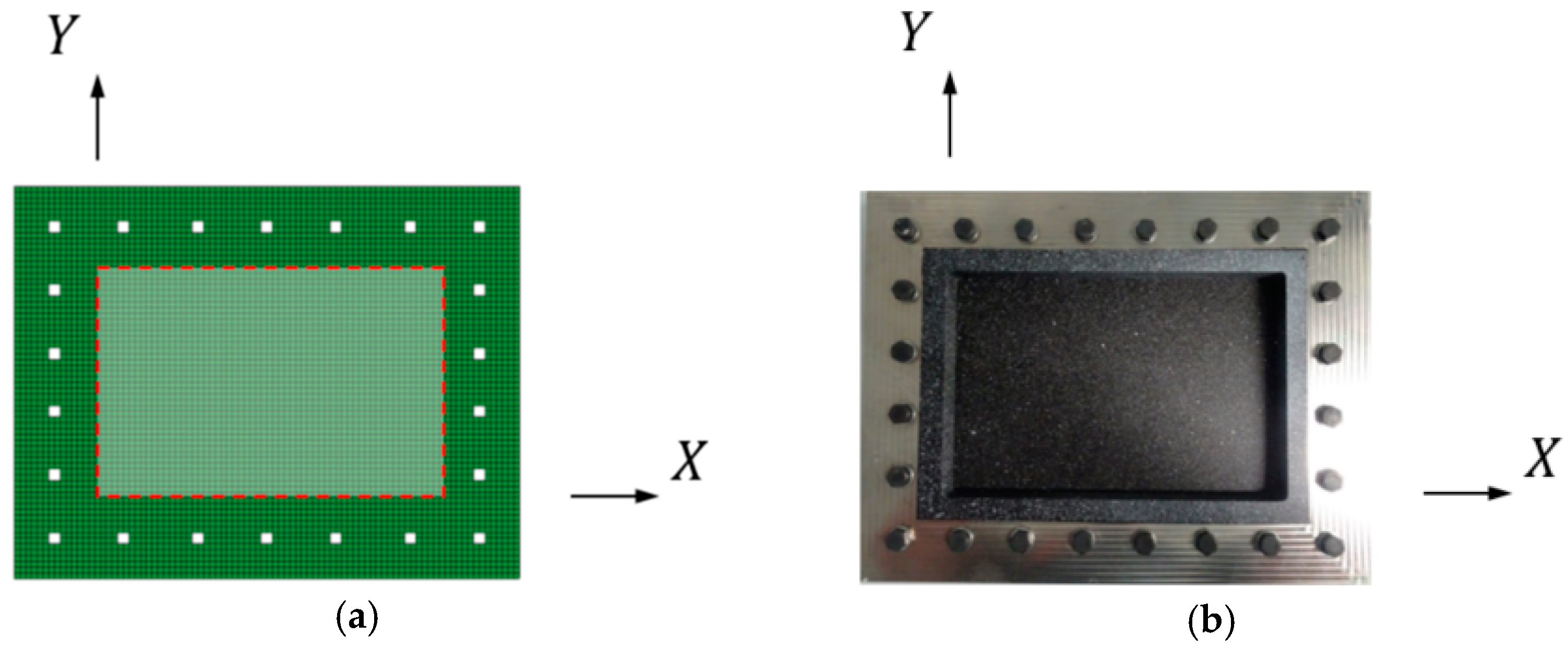
In the second step, the defined design space was examined for plates presenting mode jumping in their post-buckling range. At the beginning, a generic symmetric and balanced stacking orientation was chosen. The laminates were studied using two finite element (FE) analyses: the buckling temperatures were calculated through a linear buckling analysis, while the simulations for plate nonlinear behavior were performed using a dynamic explicit procedure. All simulations were performed with the FE model reported in Figure 4 and using the software Abaqus (Dassault Systemes, Paris, France).
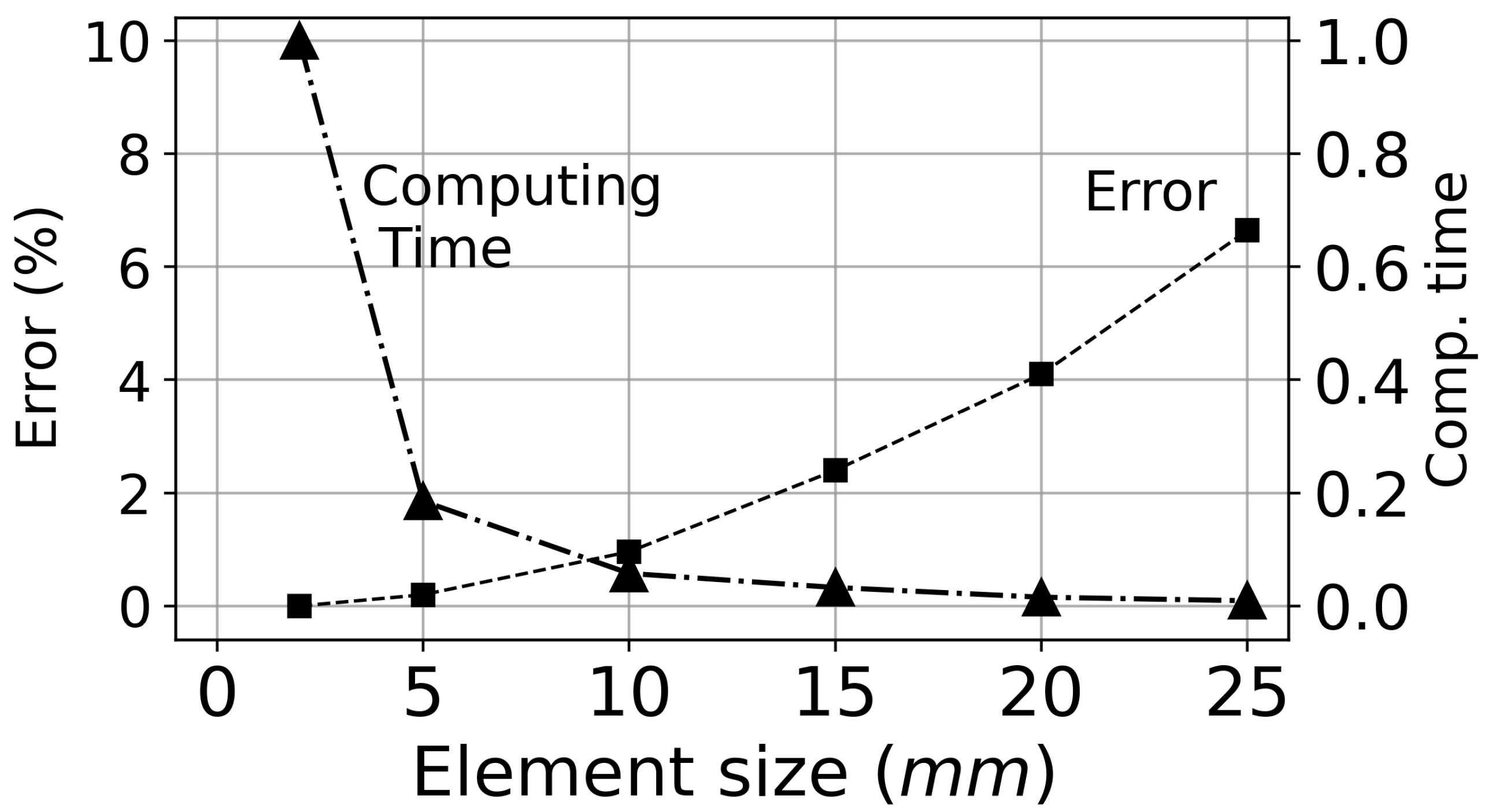
The models present dimensions of . Boundary conditions were introduced considering the surrounding structural frame to which the plate is attached. The frame overlaps with the outer area of the plate and has a cross section with width of , so that the plate free area is . The frame was made from material, which material properties are reported in Table 1. Plate and frame were meshed using S4R element. As the overlapping meshed areas corresponding to the plate and the frame have equal element size and nodes at identical positions, they were connected by means of a simple nodal merging operation. The influence of element size over the linear buckling temperature is reported in Figure 5, where both error and normalized computational time are plotted versus element size.
Adopting a 5 mm element length, an error of 0.2% can be achieved with relatively small computing times. As the overlapping meshed areas corresponding to the plate and the frame have equal element size and nodes at identical positions, they were connected by means of a simple nodal merging operation. Due to this modelling simplification, no friction or slipping effects between plate and frame is considered. During the loading, the plate expansions are constrained by the much stiffer frame, that is, in any case, allowed to expand freely. For all the analysis it was assumed that both plate and boundary conditions are always at the same temperature.
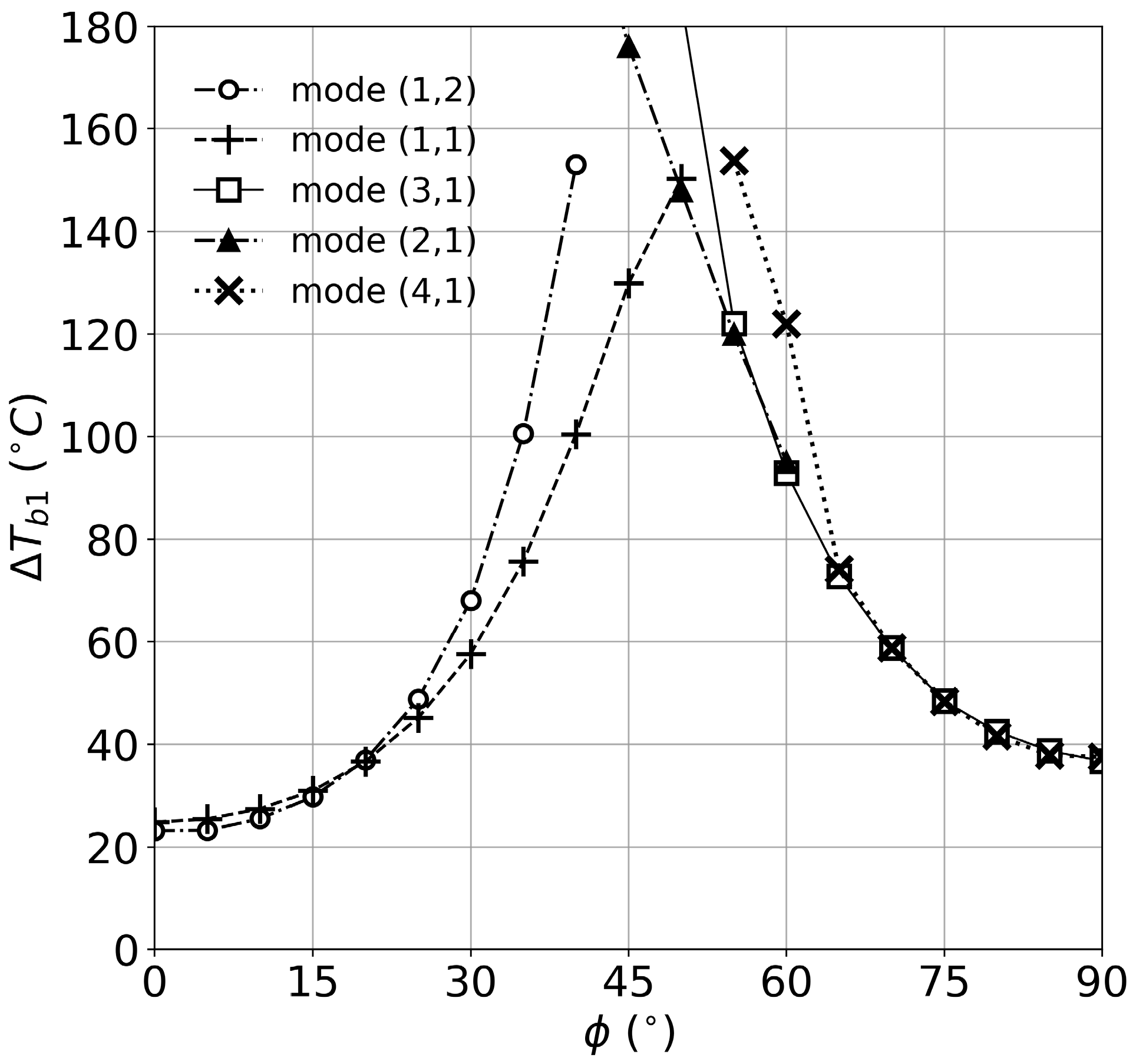
A set of linear buckling analysis for laminates with stacking is displayed in Figure 6, ranging the value of from to in increments. A total of five curves, each one collecting the eigenvalues from a particular mode shape, are reported. For each value of , at least two eigenvalues are reported: the lowest eigenvalue defines the buckling temperature as well as its corresponding buckling shape; conversely, higher eigenvalues indicate that the plate has alternative states of equilibrium at a temperature higher than . For a plate to naturally jump into another mode shape, the final-state mode shape must be captured as a higher eigenvalue in the linear buckling analysis. For instance, for , the plate reaches buckling at a under mode , and a second eigenvalue for mode shape at .
The results for buckling temperatures obtained in Figure 6 can be divided in intervals: for values of within the range plates buckle under a mode; eigenvalues for modes and are however very close. Within the range plates buckle under a mode shape, and the distance between the curves corresponding to shapes and increases with angle . In this range, mode jumps from a to a (1,2) buckling shape are possible. For range mode is no longer present. The range of interest for laminates, valid for the selected plate geometry and boundary conditions, is defined by .
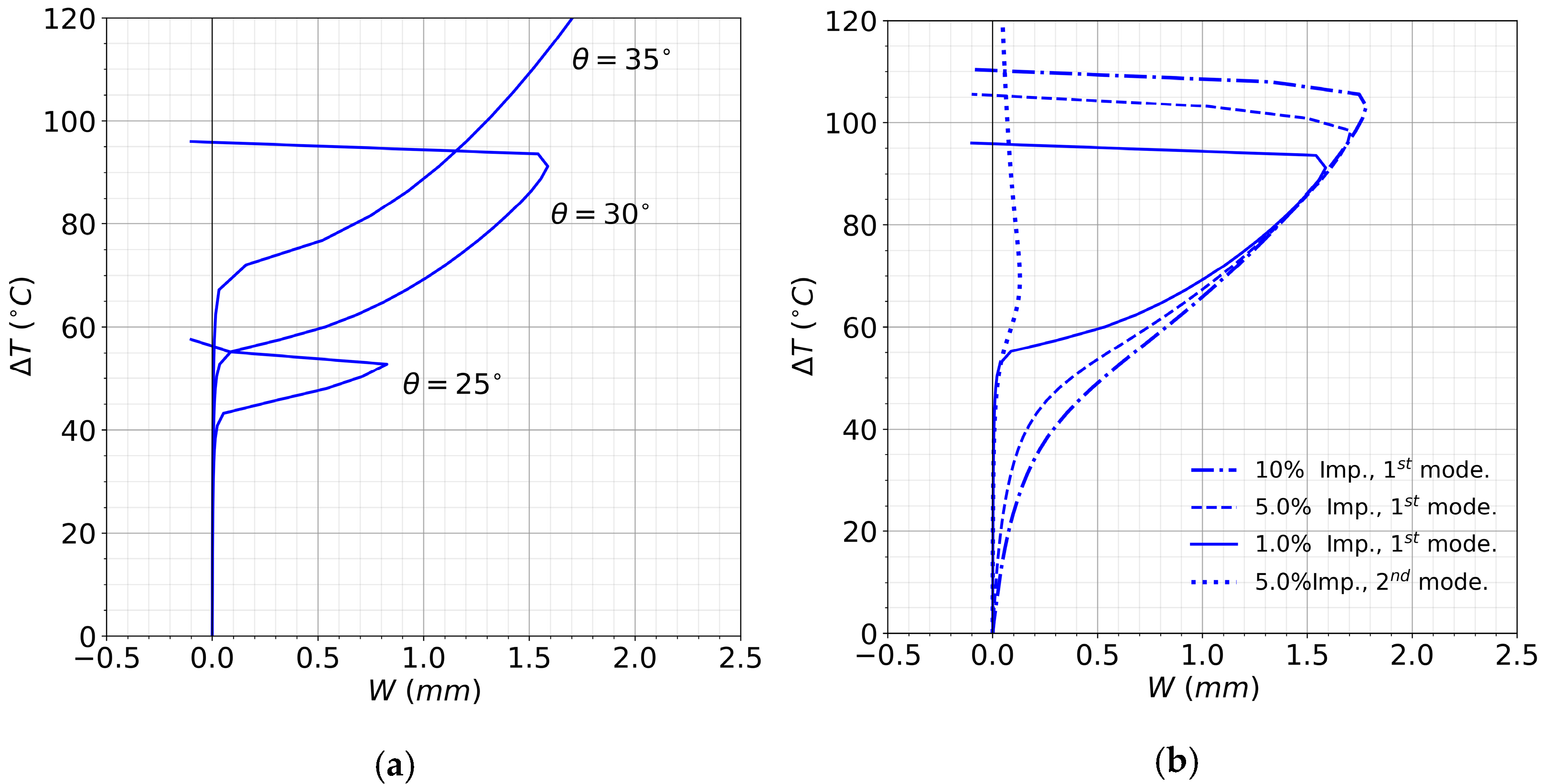
After having found a range of interest, numerical predictions for the post-buckling behavior of three composite plates with and are presented in Figure 7a. For these analyses, an initial imperfection with the shape of the 1st buckling mode and amplitude of 0.5% of plate thickness was assumed. Being the imperfection amplitude small, the nonlinear behavior comes to resemble the ideal plate nonlinear behavior. For the three plates, once is trespassed, out-of-plane deflections start increasing, assuming a buckling shape. For the mode jump is reached at , for this happens at , and for the mode jump occurs at that is beyond the maximal temperature of .
It can be observed that for the studied range of , mode jumping temperature and maximal plate deflections tend to increase with angle . This trend is also be observed for linear buckling temperature , reported in Figure 6. The reasons are the decrease of and the increase of bending stiffness along direction for growing values of , as reported in Figure 4a,b. It must also be noted that for the analyzed range of , the laminate CTE has a negative value, stretching the plate when it is heated and therefore stabilizing the plate against buckling.
The effect of plate imperfections is illustrated in Figure 7b, where the post-buckling behavior of the composite plate with laminate and different imperfections is reported. Three analyses were conducted with an initial imperfection with the shape of a buckling mode and amplitudes of , and of plate thickness, plus an analysis with a buckling mode imperfection and amplitude of of plate thickness. In particular, is plotted versus the out-of-plane deflections , measured in the center of the plate. The plate with the imperfection amplitude, represented as a continuous line, starts deflecting out of plane at a temperature close to the linear eigenvalue buckling temperature reported in Figure 6. Then, the deflection keeps growing till an abrupt mode change happens at . An analogue behavior can be observed in the curves for 5% and 10% imperfection amplitude, reported in Figure 7b as dashed and dot-dashed lines, where tends to increase with imperfection amplitude up to and respectively. However, if an initial imperfection with the shape of the 2nd mode is assumed instead, the mode jump temperature decreases, and with a sufficiently large imperfection amplitude, the plate buckles directly under a mode, skipping the lowest eigenvalue shape.
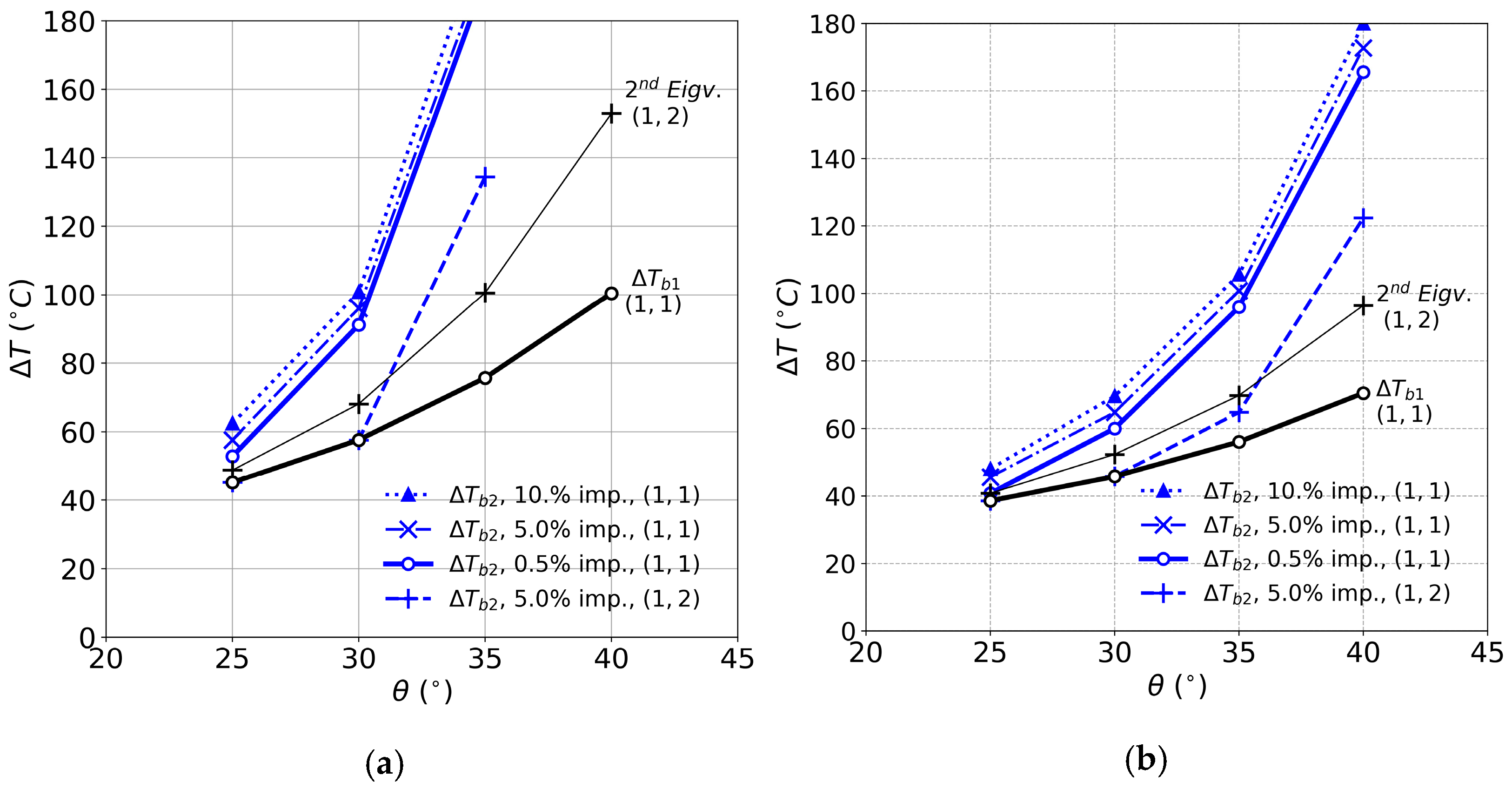
A parametric study is so conducted for laminates within the range of interest and the results are presented in Figure 8a, where both linear and nonlinear plate behavior are reported. The black bold line collects the 1st eigenvalues or buckling temperatures obtained in the linear buckling analysis, while the black thin line reports the 2nd linear eigenvalue: for instance, considering , the figure shows that the plate has the first eigenvalue at , and has a second eigenvalue at with a mode shape . The blue curves report the mode jumping temperatures for different imperfection shapes and amplitudes: the blue bold line collects values of for plates with 1st mode imperfection amplitude, the blue dot-dashed and dotted lines report values of for 5% and 10% imperfection amplitude, and at last, a blue dashed line captures values of for a 5% imperfection shape with a 2nd mode shape. Considering a plate with and , and of 1st mode imperfection amplitudes, the plate would find a mode jump at , and respectively, matching values previously reported in Figure 7b. It can be observed how for all analyzed values of , increasing amplitudes of 1st mode shape imperfection tend to rise . Conversely, 2nd mode imperfections tend to decrease . Within the range , the lines for and overlap, meaning that the plate buckles directly under a shape. layup shows a beyond , so the remaining candidate layups are and .
In the third and last step, the stacking orientations were improved by fine-tuning the layups. The objective was to make them more suitable for experimentation by decreasing both and . This can be achieved by using a generic angle-ply laminate in the form , where both angles are smaller than and the outer layer angle is significantly larger than . Taking for example the bending stiffness along axis does not decrease substantially, as is mainly formed by the contributions of the outer plies and angle remains constant. On the other hand, increases significantly, and also increases, changes its sign and becomes positive. Results for are reported in Figure 8b for the range . For the considered values of , it can be appreciated a decrease of both and . As a consequence, laminates with show a mode jump within range, even if a moderate 2nd mode imperfection is present. Consequently, two stacking orientations of the type are selected for experimentation: and .
4. Test Setup
Three specimens were manufactured and tested. The first plate was made in aluminum alloy [31] with a thickness of . The aim of this first test was assessing the functionality of the test setup and providing a benchmark using an isotropic material with well-defined properties. The second and third specimens were made of composite material, with stacking orientations and . For the manufacturing of the plates, each individual layer was cut in an automated cutting table in order to ensure the accuracy in the ply orientation. After that, the layers were stacked by hand and ultimately cured in an autoclave.
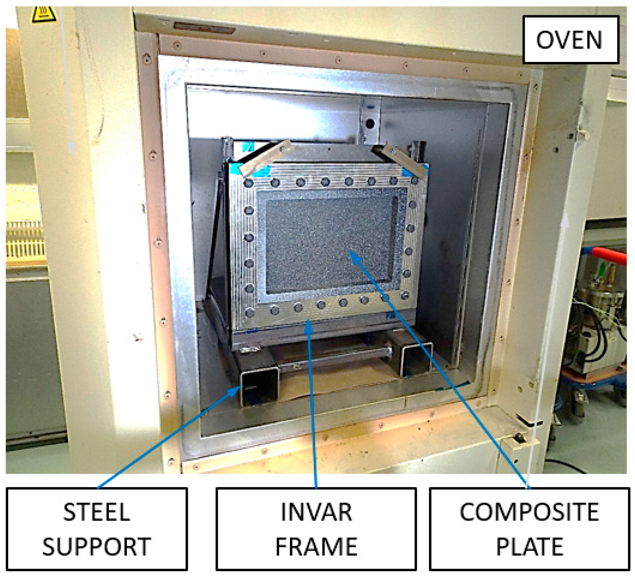
For the tests, the plate is fixed in the frame, which has the function of providing support to the plate as well as restraining its thermal expansion during the test, as shown in Figure 8. The frame is composed of two symmetric parts between which the plate is placed and then assembled together with steel bolts. The frame is made of material, which has a very low CTE.
Before a test starts, the plate and the frame have to be bolted together. The frame relies on the bolted joint to restraint the thermal expansion in the plate. The selected steel bolts have a CTE of , which is much higher than the CTE of material. The assembly torque needs to be high enough to ensure that not too much bolt pretension is lost through heating due to the difference in CTE between frame and bolts. A total assembly torque of is gradually brought to the fixture in three levels, following a crossed path to ensure uniform compression throughout the frame.
To induce the temperature increment, a Vötsch brand oven was used (Vötsch Industrietechnik GmbH, Reiskirchen, DE). It had a volume capacity of . A metallic steel support, reported in Figure 9, was used to keep the frame in a vertical position.
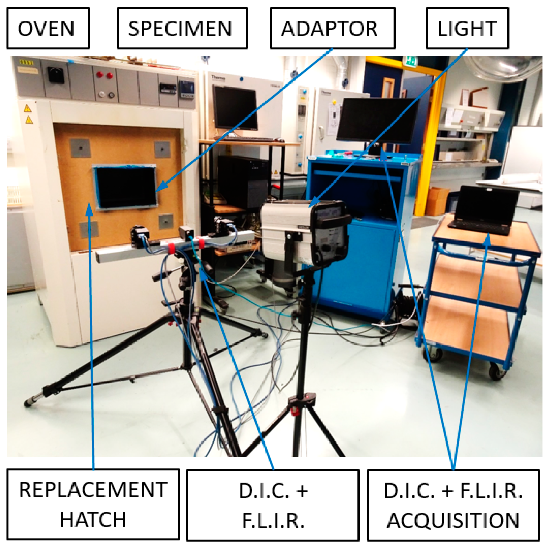
The test setup is presented in Figure 10. For the test, the original door of the oven is removed and substituted by a replacement wooden hatch with an inner ceramic lining. This hatch has a rectangular hole that allows direct visual contact with the plate for measurement acquisition. A rectangular, metallic adaptor with the same cross section as the hole is used for sealing gap between frame and hatch.
The acquisition systems collect measurements for both displacement and temperature of the plate during the complete duration of the experiment. The measurement of the out-of-plane displacement is performed with a Vic3D Digital Image Correlation (DIC) system (Correlated Solutions, Irmo, SC, USA), equipped with two cameras. The plate has to be painted with a white speckle pattern over black background. During the tests, the temperature is monitored using a thermocouple sensor placed at the center of the plate and using an A65 thermocamera (FLIR Systems, Arlington, VA, USA) placed on the outside of the oven.
In the FE analysis the plate is loaded by applying temperature increments with respect to the initial reference temperature. In order to being able to compare experimental results with numerical analysis, a reference temperature must be added to applied in the analysis. Indeed it is considered that at the plate is in an in-plane stress free state. was calculated here as the average temperature before and after bolting operation, measured in the fixture. Thus, the equation holds.
The tests consist in the gradual, monotonic heating of the plate and frame. Thermocouples start recording 10 minutes before test start. Once the test initiates, DIC and FLIR thermocamera system start recording data. For all measurement system, an acquisition rate of 1 measurement every was used.
5. Thermal Tests
The first test was performed with the plate made in aluminum alloy of thickness. The temperature path measured by the thermocouple is displayed in Figure 11. The goal temperature path into the oven is represented as a black bold line, while temperature measured in the thermocouple is represented as a red bold line. A large difference between the two curves can be appreciated. It is believed this difference was caused by air convection on the external face of the plate.
The contour plots for numerical and experimental deflections are presented in Figure 12. For all numerical analyses, a 1st mode shape imperfection with a amplitude was considered. The obtained experimental plots show reasonably good correlation with the numerical results: predicted and obtained buckling shapes are matching in shape, even if the experimental values are larger than the predictions.
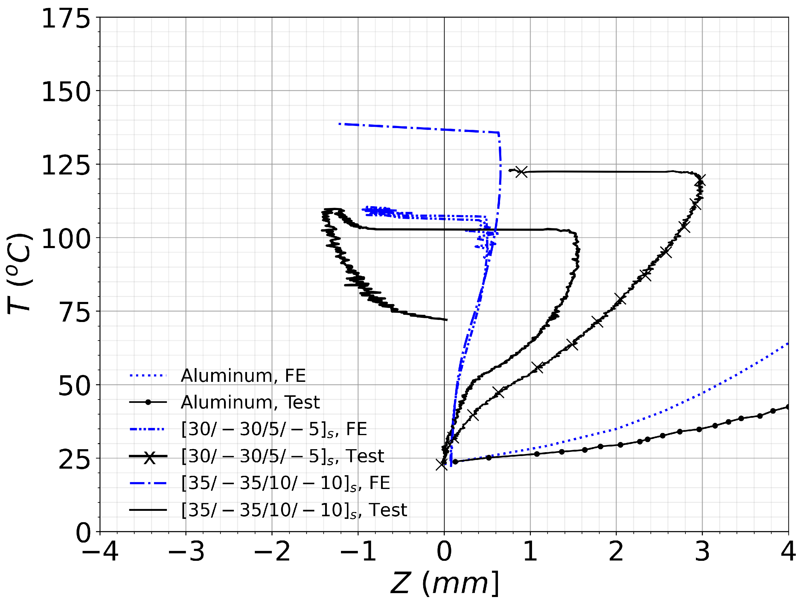
This becomes evident in the curves plotted in Figure 13 where -coordinate was plotted versus the temperature for the three plates. For the aluminum alloy plate the -coordinate was measured at plate position . Two curves are plotted, one blue dotted and a black curve with round markers representing the FE and experimental results, respectively. Even if the experimental deflections result to be noticeably larger, the numerical prediction captures the essence of the plate nonlinear behavior. The metallic plate shows no mode jumping.
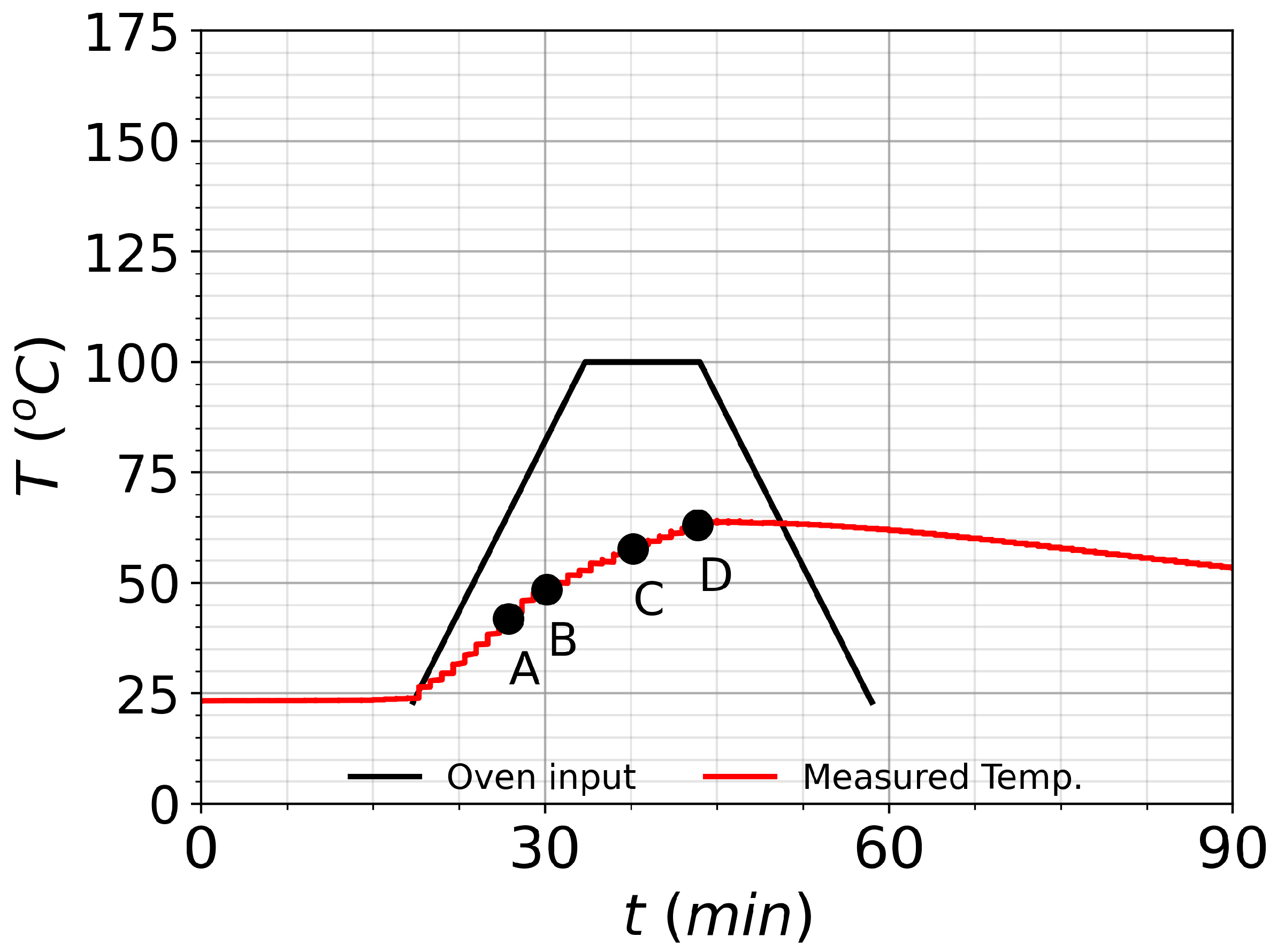
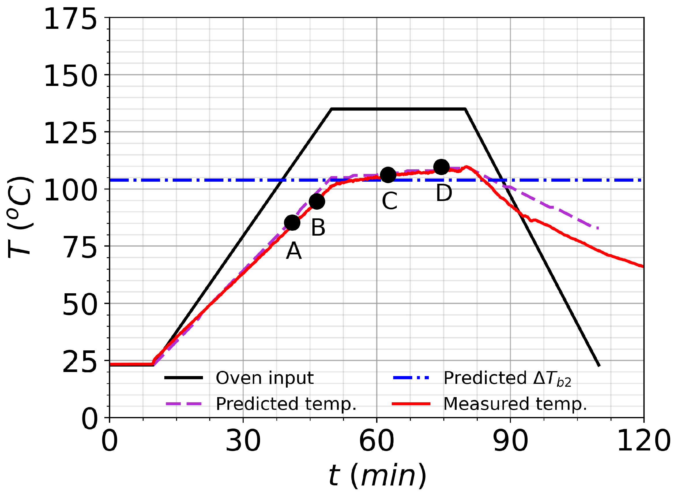
The second test was performed on the composite plate with layup. A graph of temperature as a function of time is reported in Figure 14. The ideal temperature cycle is represented as a black bold line, labelled as “Oven input”. In practice the plate never reaches the programmed temperature, so a prediction was performed to ensure that the desired temperature was reached; this estimation, represented as a bold violet line, was performed using data from two preliminary tests, where the plate was heated at two different temperature rates. This violet line was also used for the numerical simulation of the plate. Using the differences between programmed and obtained temperature rates in both experiments, for a desired plate temperature rate an oven input program rate can be extrapolated.
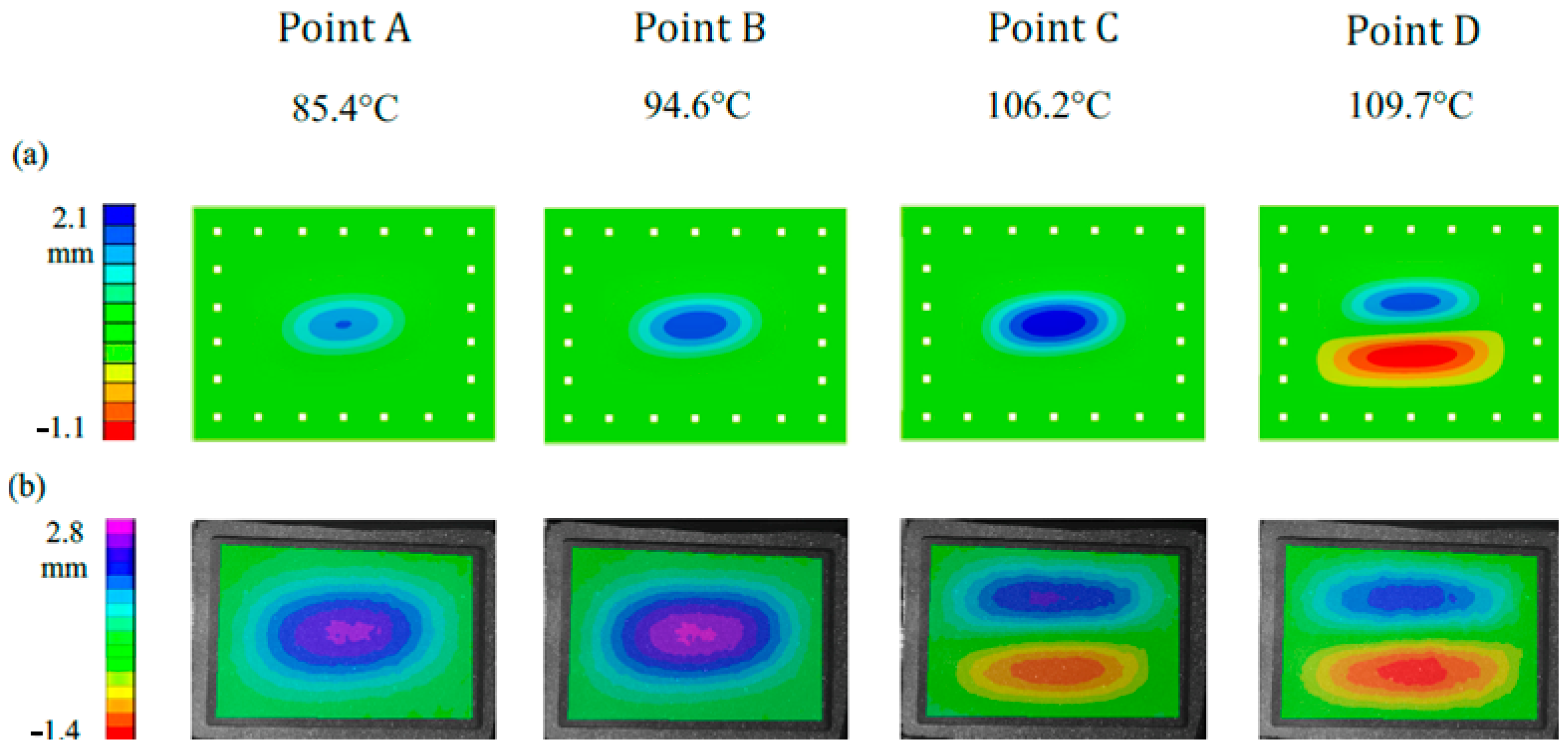
The expected value for mode jumping is plotted in the graph as a horizontal dot-dashed blue line. The temperature measured in the plate with the thermocouple is depicted as a red bold line. It closely matches the predicted temperature curve, in violet, and crosses it at the numerically expected temperature . In Figure 15 experimental and numerical plots are reported. Temperature points and correspond to the points in which the plate is heated and the out-of-plane displacements are clearly visible in the form of a buckling shape. At temperature values and a change in mode buckling into a shape is registered. When observing the FE simulations at point the mode jump has still not happened.
This difference becomes evident when observing Figure 13, where plate -position is measured at . In the two curves for laminate , the black line for the test and the dot-dashed blue line for the FE analysis are displayed. A change on sign in coordinate takes place at for the numerical prediction and at for the experimental result. Thus, the mode jump took place slightly earlier than what the FE simulation indicates. Additionally, minutes after point the temperature in the plate becomes maximum and after that it starts decreasing. When the plate cools down to the mode jump temperature , it does not spontaneously jump back into the original one half-wave configuration but it remains at a shape till showing some sort of hysteresis behavior.
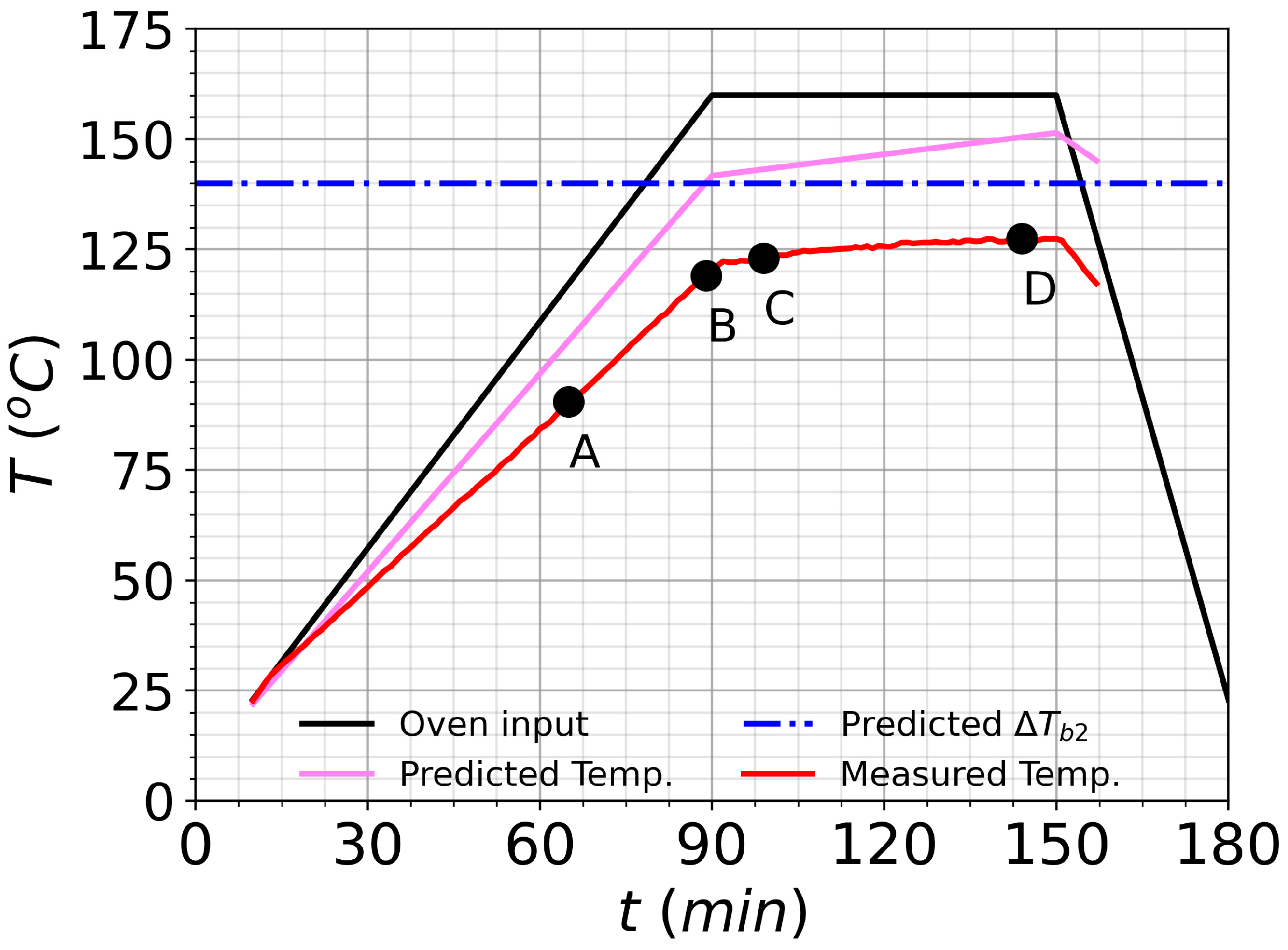
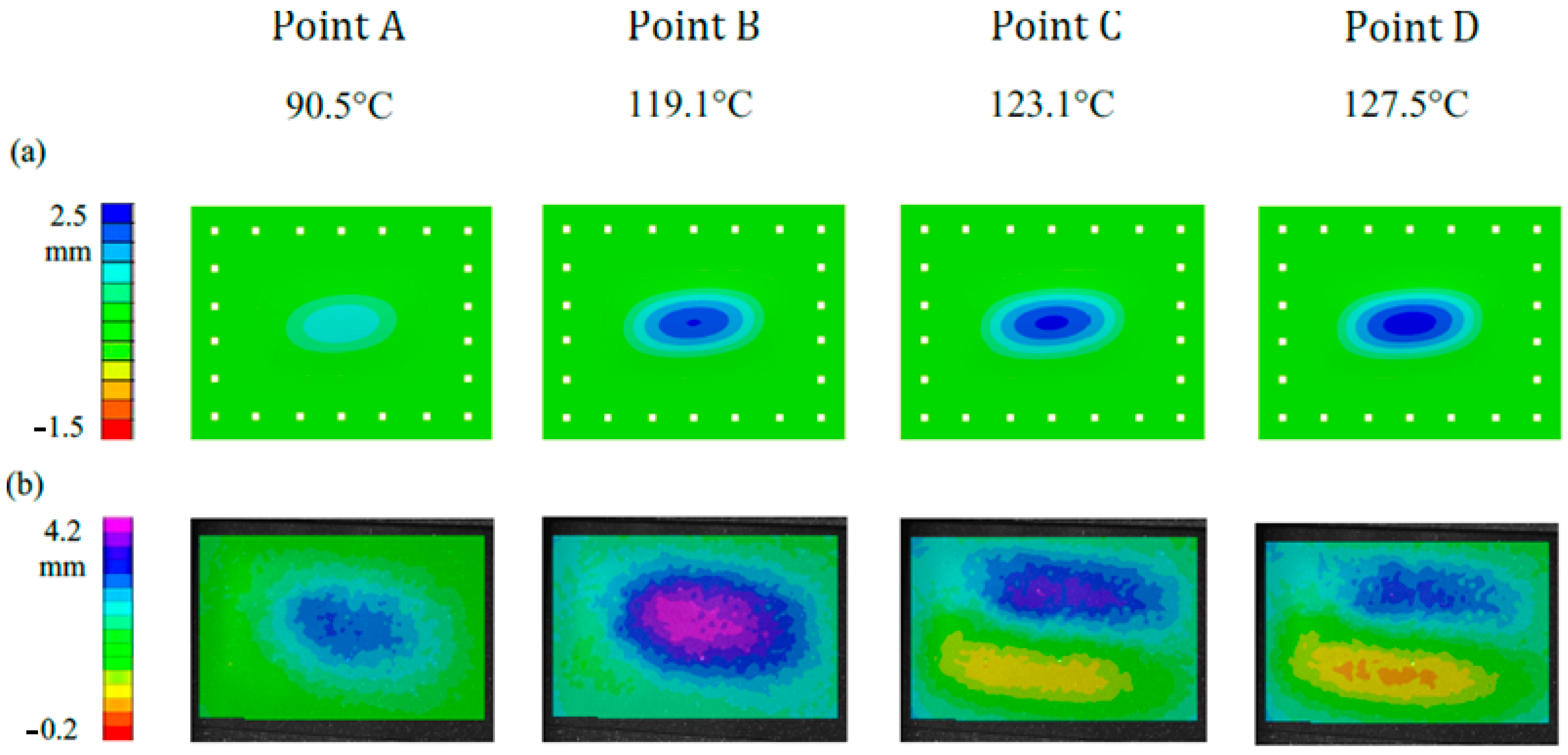
The third test was performed on the composite plate with laminate. The heating diagram in Figure 16 shows that the curves for experimental temperature and estimated mode jump temperature do not cross, hence the temperature estimation was not accurate enough. However, in Figure 17, the experimental image of point shows that a mode jump is indeed captured, differing from FE prediction which still shows a buckling mode. This mode jump is also observable in Figure 13, where, although the sign of does not change, it experiences a sudden drop at . As occurred with previous plate , the predicted mode jump temperature happens at a larger temperature, at .
A brief comparison of the three plates is here presented. The curves in Figure 13 indicate that for all cases plates show larger deflections than in the FE predictions: they are 33% higher for the plate and for the plate. In the case of the two tested composite plates, the plate with layup shows much larger deflections than the plate with layup. Both plates present a mode jump, being the temperature higher for the plate. For both composite plates the mode jump manifests at a slightly lower temperature than in the numerical prediction.
The discrepancies found between predictions and experimental results can be attributed to multiple factors. In the FE models, possible source of uncertainty is mainly the temperature dependency of material properties. Regarding the tests, the sources can be different: deviation from nominal values in material properties, change in material properties due to sustained heating, small variations in the ply angles due to the manufacturing process, relaxation in the boundary conditions due to the thermal expansion in the steel bolts, irregular heating in the specimen and geometrical imperfections of the plate. Even though the differences with the prediction are evident, the dynamic explicit procedure successfully captures the tendency to show mode jumping in the studied composite plates when these are under heating loading condition. Numerical predictions can be improved by individually addressing all previously mentioned factors. However, even though these deserve independent attention, they bring complexity and they therefore remain out of scope for the present investigation. Only the initial imperfection over is addressed here: as shown in Section 3, 1st mode imperfection patterns with a amplitude tend to stabilize the nonlinear range of the plate rising , while plate imperfections dominated by other modes shapes may decrease the mode jumping temperature or even neutralize the effect completely. All FE predictions reported in Figure 13 used a 1st mode, imperfection amplitude for all cases, while more adverse imperfections may have been present. Indeed, buckling fixtures can imprint a certain imperfection in the plate which can influences its buckling shape. Finally, the position of the heating source is also noteworthy: the tested plate is heated only from one side, and due to this, a through-thickness temperature gradient appears in the plate. This creates a thermal moment that can help the plate overcoming potentially disruptive initial imperfections, buckling into a (1,1) mode shape, as all three experiments buckle under a (1,1) shape, with the maximum deflection area directed towards the interior of the oven.
Based on previous results, 1st mode geometrical imperfections and slight panel curvatures could be used deliberately to stabilize the post-buckling shape in composite panels and help better control the mode jumping effect. Mild geometrical patters such as panel beadings have been successfully used in the past for structural stabilization of thermally post-buckled structures [32], and may offer interesting properties towards applications of mode jumping. Also, morphing applications using mode jumping should take advantage of heating asymmetries present in aerospace applications such high-speed aircraft or satellites, where the structure is heated in only one side due to aerodynamic friction or solar radiation.
6. Conclusions
In this study the thermal buckling and post-buckling behavior of composite plates was investigated. Plates were studied using both numerical and experimental techniques. A methodology for selecting composite plates showing mode jumping under heating was presented. Linear buckling eigenvalue analysis proved useful for the identification of desired secondary mode shapes, while dynamic explicit analysis was able to capture this event and give estimations for mode jumping temperatures. Additionally, parametric analysis predicted a stabilizing influence of 1st mode imperfections with diverse amplitudes over the post-buckling shape increasing the mode jumping temperature, while 2nd mode imperfections of comparable amplitude appeared to have a destructive effect over it. Thus, inducing (1,1) imperfections on composite panels could be advantageous if mode jumps are sought. As a result of the preliminary analysis, two plates made in AS4/8552 composite material with layups and were selected for experimentation in a novel test setup. An additional plate made in 2024T3 aluminum alloy was selected as a benchmark case and to demonstrate the functionality of the setup. The post-buckling behavior was successfully reproduced in all plates, while mode jumping was successfully captured for both composite plates. The experimental deflections resulted larger than the predicted values for all three tested plates. For the composite plates, mode jumping happened at temperatures lower than predicted, being the largest difference limited to . Even if discrepancies with numerical predictions are reported, nonlinear numerical procedures succeeded in capturing the trends and overall behavior in all plates. It is believed that sources for discrepancies may range from temperature dependent material properties, manufacturing or assembly defects. Also, potential morphing applications using mode jumping should take advantage of heating asymmetries present in aerospace applications. These results can be valuable as a preliminary study when considering applications of thermally triggered buckling shape change in aerospace applications.
Author Contributions
Conceptualization, J.G.Á. and C.B.; methodology, J.G.Á. and C.B.; software, J.G.Á.; validation, J.G.Á.; formal analysis, J.G.Á.; investigation, J.G.Á.; resources, C.B.; data curation, J.G.Á.; writing—original draft preparation, J.G.Á. and C.B.; writing—review and editing, J.G.Á. and C.B.; visualization, J.G.Á.; supervision, C.B.; project administration, J.G.Á. and C.B.; funding acquisition, C.B. All authors have read and agreed to the published version of the manuscript.
Funding
This research received no external funding.
Institutional Review Board Statement
Not applicable.
Informed Consent Statement
Not applicable.
Data Availability Statement
Data available under DOI: 10.4121/14061968.
Conflicts of Interest
The authors declare no conflict of interest.
References
- Wu, Z.; Weaver, P.M.; Raju, G. Postbuckling optimisation of variable angle tow composite plates. Compos. Struct. 2013, 103, 34–42. [Google Scholar] [CrossRef] [Green Version]
- Vescovini, R.; Bisagni, C. Two-step procedure for fast post-buckling analysis of composite stiffened panels. Comput. Struct. 2013, 128, 38–47. [Google Scholar] [CrossRef]
- Hu, N.; Burgueño, R. Buckling-induced smart applications: Recent advances and trends. Smart Mater. Struct. 2015, 24, 1–21. [Google Scholar] [CrossRef]
- Vos, R.; Barrett, R.; De Breuker, R.; Tiso, P. Post-buckled precompressed elements: A new class of control actuators for morphing wing UAVs. Smart Mater. Struct. 2007, 16, 919–926. [Google Scholar] [CrossRef] [Green Version]
- Runkel, F.; Reber, A.; Molinari, G.; Arrieta, A.; Ermanni, P. Passive twisting of composite beam structures by elastic instabilities. Compos. Struct. 2016, 147, 274–285. [Google Scholar] [CrossRef]
- Eckstein, E.; Pirrera, A.; Weaver, P.M. Thermally Driven Morphing and Snap-Through Behavior of Hybrid Laminate Shells. AIAA J. 2016, 54, 1778–1788. [Google Scholar] [CrossRef] [Green Version]
- Eckstein, E.; Pirrera, A.; Weaver, P. Morphing high-temperature composite plates utilizing thermal gradients. Compos. Struct. 2013, 100, 363–372. [Google Scholar] [CrossRef]
- Nali, P.; Carrera, E. Accurate Buckling Analysis of Composite Layered Plates with Combined Thermal and Mechanical Loadings. J. Therm. Stress. 2013, 36, 1–18. [Google Scholar] [CrossRef]
- Tawk, I.; Navarro, P.; Ferrero, J.-F.; Barrau, J.-J.; Abdullah, E. Composite delamination modelling using a multi-layered solid element. Compos. Sci. Technol. 2010, 70, 207–214. [Google Scholar] [CrossRef]
- Fabbrocino, F.; Funari, M.F.; Greco, F.; Lonetti, P.; Luciano, R.; Penna, R. Dynamic crack growth based on moving mesh method. Compos. Part B Eng. 2019, 174, 107053. [Google Scholar] [CrossRef]
- Shiau, L.-C.; Kuo, S.-Y. Free Vibration of Thermally Buckled Composite Sandwich Plates. J. Vib. Acoust. 2005, 128, 1–7. [Google Scholar] [CrossRef]
- Falzon, B.; Hitchings, D. Capturing mode-switching in postbuckling composite panels using a modified explicit procedure. Compos. Struct. 2003, 60, 447–453. [Google Scholar] [CrossRef]
- Falzon, B.G.; Cerini, M. A study of secondary instabilities in postbuckling composite aerostructures. Aeronaut. J. 2007, 111, 715–729. [Google Scholar] [CrossRef]
- Arbelo, M.A.; De Almeida, S.F.; Donadon, M.V.; Rett, S.R.; Degenhardt, R.; Castro, S.G.; Kalniņš, K.; Ozoliņš, O. Vibration correlation technique for the estimation of real boundary conditions and buckling load of unstiffened plates and cylindrical shells. Thin-Walled Struct. 2014, 79, 119–128. [Google Scholar] [CrossRef]
- Arbelo, M.A.; Kalnins, K.; Ozolins, O.; Skukis, E.; Castro, S.G.; Degenhardt, R. Experimental and numerical estimation of buckling load on unstiffened cylindrical shells using a vibration correlation technique. Thin-Walled Struct. 2015, 94, 273–279. [Google Scholar] [CrossRef]
- Bisagni, C. Dynamic buckling of fiber composite shells under impulsive axial compression. Thin-Walled Struct. 2005, 43, 499–514. [Google Scholar] [CrossRef]
- Bisagni, C.; Cordisco, P. Post-buckling and collapse experiments of stiffened composite cylindrical shells subjected to axial loading and torque. Compos. Struct. 2006, 73, 138–149. [Google Scholar] [CrossRef]
- Labans, E.; Abramovich, H.; Bisagni, C. An experimental vibration-buckling investigation on classical and variable angle tow composite shells under axial compression. J. Sound Vib. 2019, 449, 315–329. [Google Scholar] [CrossRef]
- Ehrhardt, D.A.; Virgin, L.N. Experiments on the thermal post-buckling of panels, including localized heating. J. Sound Vib. 2019, 439, 300–309. [Google Scholar] [CrossRef]
- Percy, W.; Fields, R. Buckling analysis and test correlation of hat stiffened panels for hypersonic vehicles. In Proceedings of the 2nd International Aerospace Planes Conference, Reston, VA, USA, 29–31 October 1990; American Institute of Aeronautics and Astronautics: Reston, VA, USA, 1990. [Google Scholar] [CrossRef]
- Thompson, R.C.; Richards, W.L. NASA Technical Memorandum 104243—Thermal-Structural Buckling Tests Panel. 1991. Available online: https://ntrs.nasa.gov/citations/19920006186 (accessed on 15 November 2020).
- Rakow, J.F.; Waas, A.M. Thermal Buckling of Metal Foam Sandwich Panels for Convective Thermal Protection Systems. J. Spacecr. Rocket. 2005, 42, 832–844. [Google Scholar] [CrossRef]
- Murphy, K.D.; Virgin, L.N.; Rizzi, S.A. The Effect of Thermal Prestress on the Free Vibration Characteristics of Clamped Rectangular Plates: Theory and Experiment. J. Vib. Acoust. 1997, 119, 243–249. [Google Scholar] [CrossRef]
- Amabili, M.; Tajahmadi, M.R.S. Thermal post-buckling of laminated and isotropic rectangular plates with fixed edges: Comparison of experimental and numerical results. Proc. Inst. Mech. Eng. Part C J. Mech. Eng. Sci. 2012, 226, 2393–2401. [Google Scholar] [CrossRef]
- Thornton, E.A. Thermal Buckling of Plates and Shells. Appl. Mech. Rev. 1993, 46, 485–506. [Google Scholar] [CrossRef] [Green Version]
- Breivik, N.L.; Hyer, M.W. Buckling and Postbuckling Behavior of Curved Composite Panels Due to Thermal and Mechanical Loading. J. Reinf. Plast. Compos. 1998, 17, 1292–1306. [Google Scholar] [CrossRef]
- Fields, R.A.; Richards, W.L.; DeAngelis, M.V. NASA Technical Memorandum TM-2004-212039—Combined Loads Test Fixture for Thermal-Structural Testing of Aerospace Vehicle Panel Concepts. 2004. Available online: https://ntrs.nasa.gov/api/citations/20040031531/downloads/20040031531.pdf (accessed on 15 November 2020).
- Wu, K.C.; Gürdal, Z. Thermal testing of tow-placed, variable stiffness panels. In Proceedings of the 42nd AIAA/ASME/ASCE/AHS/ASC Structures, Structural Dynamics and Materials Conference and Exhibit, Seattle, WA, USA, 16–19 April 2001; American Institute for Aeronautics & Astronautics: Reston, VA, USA, 2001. [Google Scholar] [CrossRef] [Green Version]
- Xu, Y.; Ren, S.; Zhang, W.; Wu, Z.; Gong, W.; Li, H. Study of thermal buckling behavior of plain woven C/SiC composite plate using digital image correlation technique and finite element simulation. Thin-Walled Struct. 2018, 131, 385–392. [Google Scholar] [CrossRef]
- Hexcel Corporation. HexPly 8552, Product Data Sheet. 2016, pp. 1–6. Available online: https://www.hexcel.com/Resources/DataSheets/Prepreg (accessed on 15 November 2020).
- U.S. Department of Defense. Military Handbook Metallic Materials and Elements for Aerospace Structures (MIL-HDBK-5H); U.S. Department of Defense: Washington, DC, USA, 1998.
- Lee, J.; Bhatia, M. Impact of corrugations on bifurcation and thermoelastic responses of hat-stiffened panels. Thin-Walled Struct. 2019, 140, 209–221. [Google Scholar] [CrossRef]
Figure 1.
Plate geometry, boundary conditions and heating load.

Figure 2.
Thermal equilibrium path of a post-buckled composite plate.

Figure 3.
Properties of composite plates: (a) Bending stiffness for laminates; (b) CTE’s for laminates.
Figure 3.
Properties of composite plates: (a) Bending stiffness for laminates; (b) CTE’s for laminates.

Figure 4.
Plate with frame: (a) FE model; (b) Specimen.

Figure 5.
Analysis error and computational time vs. element size.

Figure 6.
Linear buckling temperatures for laminates.

Figure 7.
Mode jumping of composite plates: (a) Mode jumping temperature for laminates; (b) Effect of imperfections for laminate.
Figure 7.
Mode jumping of composite plates: (a) Mode jumping temperature for laminates; (b) Effect of imperfections for laminate.

Figure 8.
Mode jumping temperature for different laminates: (a) laminates; (b) laminates with .

Figure 9.
Specimen inside oven.

Figure 10.
Test setup.

Figure 11.
Heating cycle for aluminum alloy plate.

Figure 12.
Out-of-plane deformation for aluminum alloy plate: (a) FE analysis; (b) Test.

Figure 13.
Temperature vs. out-of-plane deformation for the three plates.

Figure 14.
Heating cycle for composite plate.

Figure 15.
Out-of-plane deformation for composite plate: (a) FE analysis; (b) Test.

Figure 16.
Heating cycle for composite plate.

Figure 17.
Out-of-plane deformation for composite plate: (a) FE analysis; (b) Test.


Table 1.
Material properties.
| 135 | 9.68 | 5.6 | 0.30 | 0.28 | 28 | 0.181 | 1.58 | |
| 140 | 0.33 | 1.5 | 8.05 | |||||
| 72.3 | 0.33 | 24 | 2.73 | |||||
Publisher’s Note: MDPI stays neutral with regard to jurisdictional claims in published maps and institutional affiliations. |
© 2021 by the authors. Licensee MDPI, Basel, Switzerland. This article is an open access article distributed under the terms and conditions of the Creative Commons Attribution (CC BY) license (http://creativecommons.org/licenses/by/4.0/).
Share and Cite
MDPI and ACS Style
Gutiérrez Álvarez, J.; Bisagni, C. A Study on Thermal Buckling and Mode Jumping of Metallic and Composite Plates. Aerospace 2021, 8, 56. https://0-doi-org.brum.beds.ac.uk/10.3390/aerospace8020056
AMA Style
Gutiérrez Álvarez J, Bisagni C. A Study on Thermal Buckling and Mode Jumping of Metallic and Composite Plates. Aerospace. 2021; 8(2):56. https://0-doi-org.brum.beds.ac.uk/10.3390/aerospace8020056
Chicago/Turabian StyleGutiérrez Álvarez, Javier, and Chiara Bisagni. 2021. "A Study on Thermal Buckling and Mode Jumping of Metallic and Composite Plates" Aerospace 8, no. 2: 56. https://0-doi-org.brum.beds.ac.uk/10.3390/aerospace8020056
Note that from the first issue of 2016, this journal uses article numbers instead of page numbers. See further details here.