Article

InnoCube—A Wireless Satellite Platform to Demonstrate Innovative Technologies

1
Institute of Space Systems (IRAS), TU Braunschweig, 38108 Braunschweig, Germany
2
Chair of Space Technology, TU Berlin, 10587 Berlin, Germany
3
Chair of Computer Science VIII, Aerospace Information Technology, University Wuerzburg, 97070 Würzburg, Germany
*
Author to whom correspondence should be addressed.
Submission received: 28 February 2021 / Revised: 18 April 2021 / Accepted: 29 April 2021 / Published: 4 May 2021
(This article belongs to the Special Issue Small Satellite Technologies and Mission Concepts)

Abstract

:
A new innovative satellite mission, the Innovative CubeSat for Education (InnoCube), is addressed. The goal of the mission is to demonstrate “the wireless satellite”, which replaces the data harness by robust, high-speed, real-time, very short-range radio communications using the SKITH (SKIpTheHarness) technology. This will make InnoCube the first wireless satellite in history. Another technology demonstration is an experimental energy-storing satellite structure that was developed in the previous Wall#E project and might replace conventional battery technology in the future. As a further payload, the hardware for the concept of a software-based solution for receiving signals from Global Navigation Satellite Systems (GNSS) will be developed to enable precise position determination of the CubeSat. Aside from technical goals this work aims to be of use in the teaching of engineering skills and practical sustainable education of students, important technical and scientific publications, and the increase of university skills. This article gives an overview of the overall design of the InnoCube.

1. Introduction

CubeSats have evolved significantly over the last 10 years. While they were once used primarily for educational purposes, they are now capable of performing more complex tasks. The goal of the research at the Institute of Space Systems of Technical University of Braunschweig (IRAS) is to further enhance the performance of small satellites. In order to tackle even more complex tasks, such as supporting active debris removal (ADR) or scientific missions, new technologies are implemented. The chair of Information Technology for Aerospace at the University of Wuerzburg is mainly researching reliable distributed and autonomous computing systems, focusing on space and aeronautic projects. Both universities partnered and are jointly developing a 3U–CubeSat for innovative technology advancement and practical, sustainable education of students. The aim of the project is the technology demonstration of two innovative technologies, which have been previously developed and funded by German Aerospace Center (DLR) InnoSpace Masters program: SKITH (SKIpTheHarness) and Wall#E. InnoCube concludes its three year development phase with the launch into orbit in 2023, aiming for a mission of at least one year. The planned CubeSat will be developed by students and research staff, going through all phases of a space project life cycle. The following article describes the mission framework with a focus on the design criteria and operational concept. Therefore, Section 2 covers the mission, payloads and boundary conditions, Section 3 gives an overview of the satellite bus including the software, while Section 4 gives a summary and outlook.

2. Mission

The goals of the CubeSat project can be divided into four categories:
  • Long-term goals;
  • Technological goals;
  • Scientific goals;
  • Educational goals.
The long-term goal is to increase both universities competencies and to raise TRL of used components for further development. This is reflected in the technology goals to demonstrate SKITH in an operational environment and have the first wireless satellite bus with respect to data harness. A further goal is the assessment of the functionality of a new battery concept of a carbon-reinforced plastic structural battery in a relevant space environment. In addition, a concept of an on-orbit navigation laboratory using a software-defined Global Navigation Satellite System (GNSS) receiver and Laser Ranging Reflector Experiment (LRR) is flown. The scientific goals comprise the validation of the initial theoretical assumption and to validate the GNSS experiment using the accuracy of a miniaturized laser retro reflector for CubeSats. Additionally, if possible the LRR measurements analyses should be used for improvement in positioning accuracy applying in orbit updates to the navigation algorithms. With the anticipated highly accurate orbit data, propagators developed at IRAS [1,2], can be improved. Works in the field of space situational awareness, rendezvous, and docking for active debris removal missions can be advanced. In addition to the scientific goals, one of the main objectives (educational goals) of the project is the training of students. This includes not only component development and technical applications, but also satellite operations. In summary, the design, fabrication, launch and operation of a small satellite with the following boundary conditions are to take place within 4 years:
  • Fabrication, validation and verification of a CubeSat flight model within a maximum of 3 years;
  • Successful launch with up to three months of Launch and Early Orbit Phase (LEOP) and payload calibration;
  • Mission life expectancy of 12 months (in-orbit);
  • Verify and validate science experiments and record science data through end of mission(active) and through end of life (passive–LRR);
  • Verify and validate technologies (SKITH and WALL#E);
  • Hardware and software testing;
  • Satellite operations with students.

2.1. Orbit Design

The InnoCube satellite will not be launched with a dedicated launcher; instead, it will be brought into orbit as a secondary payload. A voluntary orbit cannot be chosen.
Therefore, different launch opportunities are being examined.
As the number of CubeSats launched have increased rapidly in the last few years, various vendors offer launch services for small satellites with different orbital parameters, perhaps the most common in popular media being SpaceX and its capabilities to offer piggyback services onboard their Starlink mission.
The major requirements considering orbit design are defined by the mission lifetime. To fulfill a minimum on-orbit mission of one year, a minimum orbit altitude of 400 km is defined. A maximum altitude of 600 km is defined by compliance with the Space Debris Mitigation guidelines, adhering to deorbiting not later than 25 years after the end of operational life.

2.1.1. Orbit Analysis

An analysis is performed concerning the orbital requirements for the payload, especially the laser ranging reflector and GNSS experiment, and the thermal environment of the satellite.
The laser ranging experiment can be operated at an altitude ranging from 400 km to 600 km with no prerequisites regarding inclination. Thus, the limiting constraint is the accessibility to the ground station in Braunschweig.
The GNSS payload can provide continuous availability from a large number of receivable satellites due to low interference and good reception geometry at all times on a low earth orbit below 3000 km ([3], see Figure 1 left). The L1 band shared by the Global Positioning System (GPS) and Galileo can provide a large number of receivable satellites in the nominal carrier frequency due to is wide main lobe [4].
A minimum inclination is necessary to access the ground station in Braunschweig, which is at a latitude of 52.26° North. Apart from financial considerations, a maximization of access time is the key consideration.
The different thermal conditions arising from different orbits are negligible, as eclipse durations are very similar in low altitude orbits. No subsystem of the satellite needs to operate in specified temperature ranges. Passive methods are being implemented to keep the satellite in safe temperature and power levels.

2.1.2. Space Debris Mitigation Guidelines

IRAS as an institute researching the subject of space debris, the Space Debris Mitigation guidelines are an important aspect in the design and operation of a satellite. The applicable guidelines include deorbiting not later than 25 years after the end of operational life, a re-entry burn up above 15 km, a minimization of risk of explosion and no generation of space debris.
The analysis tool DRAMA (Debris Risk Assessment and Mitigation Analyses) [5,6] was used for the calculation of maximum lifetime after end of operations and to confirm the maximum possible orbital altitude. The simulation resulted in a natural orbital lifetime of 17 years at an orbital altitude of 576 km (using the latest Two Line Elements (TLE) of the highest Starlink satellite [7]). Thus, the space-debris avoidance guidelines are met by a 5% margin. The simulated individual components demise between an altitude of 75 km and 80 km.
The current satellite design does neither include any deployables nor extendable structures, except for the ultra-high frequency (UHF) antennas. In addition, the operation and evaluation of the scientific payloads can be expected to provide highly accurate position data and reduce collision risk where appropriate. Thus, the requirements for minimizing the risk of explosion and no further creation of space debris are addressed by the satellite, mission design, and adherence to the CubeSat standard.

2.2. Communication Analysis

To get knowledge about contact times between the ground station and the satellite, three main orbits that fit in previous considerations are being analysed.
  • An orbit with an altitude of 550 km and an inclination of 53 degrees (SpaceX Rideshare /Starlink);
  • a sun synchronous orbit with an altitude of 550 km (various vendors, e.g., Vega Small Spacecraft Mission Service (SSMS), SpaceFlight Industries);
  • the orbit of the International Space Station (ISS) with an altitude of around 420 km and an inclination of 51.6 degrees (ISS NanoRacks CubeSat deployer).
The nature of these low Earth orbits (LEO) indicates common similarities. All orbits feature five to six contact windows per day, spanning between seven and nine minutes. Sun synchronous orbits feature two contact windows per day, consisting of two to three orbits. Considering a maximization of communication time, the favoured orbit is the Starlink orbit, averaging 9.1 min per pass with a contact time per day of 53 min. Secondly, the sun synchronous orbit reaches an average 8 min per pass and 45 min per day, respectively. The lower ISS orbit reaches 7.3 min per pass and 38 min per day. With a proposed data rate of 9600 bps, data amounts of 2.5 to 3.4 megabytes per day are expected to be transferred.

Link Budget Analysis

The quality of the proposed communication link is estimated with the formulation of conservative parameters, regarding all detrimental influences.
The mission requires the communication system to perform at an elevation angle of 5° with an orbit altitude of 600 km. The system uses UHF frequencies of the amateur–radio band with a data rate of 9600 bps. The quality of the signal is parameterized with a bit error rate of less than 10−5.
The ground station consists of a high gain antenna and a 120 W transmitter. Similar to most CubeSats, the satellite transmits with 1 W of power. The antenna of the satellite is a ground-plane antenna consisting of four monopoles, resulting in an omnidirectional radiation pattern with right–handed circular polarization.
A strong signal can be achieved in the uplink path due to high transmitting power of the ground station. The calculated link margin is 26 dB.
The downlink path is a lot more fragile, considering a noisy environment at the ground station and far less transmitting power at the satellite. Without polarization loss and the proposed data rate, a link margin of 5 dB is expected. The resulting margin in operation is expected to be higher, as the noise level of the ground station and the discrimination of the signal on the satellite need to be determined.

2.3. Power Budget Analysis

The power that is generated by four body-mounted solar panels has been determined for multiple mission scenarios using the power simulation tool from the Virtual Satellite (VIRSAT) software [8]. These panels cover the whole surface of the CubeSat except the rails and standoffs According to typical solar panels [9,10] and the dimensions of the satellite we assume an area of 0.021 m² with solar cells and an effectivity of about 29%.
The power budget has been calculated for a 550 km sun-synchronous orbit in order to cover a wide spectrum of the possible launch opportunities for InnoCube. In this orbit the time of sunlight is 3585 s, the time of eclipse is 2120 s according to a Systems Tool Kit (STK) analysis. The worst case 24 h operational scenario is as follows:
  • Electrical Power System (EPS), Receiver (Rx), Beacon und onboard computer (OBC) always ON;
  • Transmitter (Tx) 50 min within 24 h for 10 min ON and battery heater 75 min ON;
  • attitude determination and control system (ADCS) low power Mode ON + 10 min high power mode and 120 min medium power mode;
  • GNSS Payload 150 min in ON and Wall#E charging in max power mode for 15 h per 24 h;
  • Operational average temperature of the solar panel 50 °C.
The simulations and calculations of the power budget shows (Figure 2) that the system is power positive and the batteries have enough margin and can always be fully charged. The average generated power with the assumptions above is about 67 Wh in 24 h while the satellite needs 54 Wh in the described worst case scenario. The maximum power needed is about 15 Wh while in a specific ADCS mode. Therefore, the average depth of discharge (DoD) for a battery with about 77 Wh capacity [11] is <5% with the maximum DoD < 10%. This should have a positive effect on the battery degradation and lifetime.

2.4. Scientific and Technical Goals and Payloads

2.4.1. SKITH (SKIpTheHarness)

SKITH is the acronym for SKIpTheHarness, which is a very compact description of the main idea. Within the InnoCube satellite, a wireless data exchange between all satellite modules, i.e., the onboard computer (OBC), ADCS, power distribution and conditioning unit (PCDU), up-/downlink transceiver and the payload is realized. It is the first time a satellite has been designed following this approach. In this mission we aim to demonstrate the SKITH concept for CubeSats. It features some fundamental advantages over a cabled harness, which will be elaborated in the following.
The communication between on-board components within conventional satellites is based on a wired harness. Standard concepts used are point to point connections or bus structures e.g., Controller Area Network (CAN). Known issues with cabled connections are the risk of cable failures (due to broken wires or connectors), a high mass (up to 10% of total satellite [12]) and inflexibility to later design changes. The testability of the harness on an integrated satellite requires additional hardware or software effort, to inspect all connections.
To overcome these issues, the chair for aerospace information technology developed a concept that replaces all internal wired data connection by low power wireless interfaces. Subsequently, all the aforementioned failure risks are obsolete. The satellite integration becomes easier and errors due to inaccurately assembled connections are impossible, at least for data interfaces, as there is still the need for power transmission lines.
Another advantage of a wireless communication concept especially in satellites is the simplified implementation of redundancy. The wireless concept shares some characteristics with a wired bus structure. The common media is not the wire, but the spectral range of the transmission frequency. In a wired bus, the risk of one broken node, blocking the whole bus by shorting the data lines to ground, needs to be handled. A common solution for this is duplicating the bus and dedicated modules.
In a wireless concept the risk of blocking the communication channel by one broken module is not given, once this module is powered off. Thus, the only need is the ability to separately power off each module, a need that is common on satellites.
Finally testing of the interfaces can be done without a physical access to the integrated satellite. It is as simple as placing a receiver in the surroundings and analyze the data exchange in the satellite.
The SKITH interface on InnoCube will be realized by using an EFR32FG12 microcontroller by Silicon Labs. It is a commercial off the shelf (COTS) component that already includes a 2.4 GHz front end. All external elements needed are an antenna and a tuning circuit. Since the antenna is implemented on a circuit board (PCB) layout, there is only a small inductance that needs to be mounted aside the microcontroller. The HF modulation supported by the front-end is a Gaussian frequency shift keying (GFSK) or quaternary phase shift keying (QPSK). The maximum transmission power is 19 dBm, the receiver sensitivity for a GFSK modulation is −94.8 dBm at a data rate of 1 Mbps [13]. The board layout for a complete SKITH interface, including antenna, needs 25 mm by 30 mm and will be included on all modules. An image showing a PCB carrying two SKITH interfaces is shown in Section 3.5.1.

2.4.2. Radiation Test

As the EFR32FG12 microcontroller was never used in space before it has been preliminarily radiation tested. Four off-the-shelf development boards of the microcontroller were irradiated by a Cobalt-60 gamma-radiation source. They were exposed to a total dose of 13.12 krad over 20 h. While testing the controllers were powered and exchanged radio messages between each other and performed regular integrity checks of all memories. The test results show no memory errors or communication failures.
In a subsequent test another four controllers were to be irradiated until failure, but the test had to be aborted after 3.75 h due to time constraints. At the end, a total dose of 33.75 krad has been reached. Again, no errors in memory were observed. After a dose of 20 krad one controller showed less than 1% of radio packet loss, the others none.
Reference [14] estimates 1.2 krad/year for 1mm shielding in LEO. With these test results the chip is expected to be suitable for at least 1 year planned mission lifetime with a good safety margin. Due to budget constraints, high-energy proton and ion tests are not planned, but these events are typically less of a concern in a short time LEO mission.

2.4.3. Redundancy Concept

For the radio communication to work, it is important to always have only one master node active, that controls the communication. To ensure redundancy two master nodes are present but one active one is determined by the hardware switches in the power unit.
The two master nodes are connected to the power by so-called keep-off switches. These switches keep their off-state if they receive regular pulses on their control input. If these pulses are lacking for a certain period they turn to the on state. Now one master node controls the switch of the other and vice versa.
The active master node sends keep-off pulses to the other node’s switch, when it determines itself to be healthy and working. This ensures only one active master at a time. The generation of the pulse is placed in a piece of code that only executes when the radio communication is reliably working. This is the code that processes received frames. Other nodes may only send frames when they receive a sync frame from the master, so if the master receives a frame from another node, this shows reliable operation of the master’s sender and receiver. The flow of the signals is shown in Figure 3.
If anything fails, the keep-off pulses stop and the other master node boots after the timeout. If this node is working it will itself send a keep-off to the first node and disable it.
On power-on both nodes will boot at the same time. To ensure only one node stays on both master nodes are programmed to send a keep off command at start-up with a random delay. This selects one node randomly to be active and ensures no node is preferred in case it has unforeseen problems that cause this mechanism somehow to fail.
The active master node manages the redundancy of other nodes in the satellite in software by listening for status messages sent over radio. As the master node is responsible for controlling the power unit it is able to switch all other nodes on and off as needed.

2.4.4. Radio Communication Protocol

The integrated radio hardware in the EFR32FG12 microcontroller handles Open Systems Interconnection model (OSI) Layer 1 by itself. Further the hardware handles framing and checksum of Layer 2. The software, therefore, must handle radio packet collision avoidance and addressing.
To keep things simple and deterministic there is one designated master node, which controls all communication as well as the power unit. To avoid that this master is a single point of failure it is dual modular redundant. The master sends synchronization frames in regular intervals. The structure of the frames send on the radio link is outlined in Figure 4. The sync frames contain a list of relative times to the synchronization frame. These mark the time slots at which each other node may transmit. The end of the transmission slot of one node is marked by the beginning of the next. The slot length can be adjusted to account for different bandwidth requirements of the nodes. After the slot-list the master sends its payload, if any, like any other node. This can ensure a minimum bandwidth for every node. The maximum latency is depended on the maximum length of the cycle. The frame of the non-master nodes is the same except that the time-slot list is missing.
The payload contains the data of the higher level Rodos (real-time on-board dependable operating system) middleware protocol, which transmits the published topic data to all nodes.
The Rodos middleware frames which contain the topic data are transmitted in the payload. One radio frame can contain multiple Rodos middleware frames to allow full usage of the slot if there are only small frames available. Addressing is then handled inside the Rodos middleware frames with its publisher/subscriber architecture and topic IDs. Each node processes all frames and forwards the topics it is subscribed to, to its local subscribers. The middleware and topics are further described in Section 3.5.5.

2.4.5. WallE-2-Space

The goal of the experiential payload WallE-2-Space is to examine previous researched Wall#E technology [15,16] in a relevant space environment. The technology integrates energy storage functions into the supporting structures of a spacecraft, equipping the carbon fiber-reinforced plastics (CFRP) with solid-state battery materials at nanoscale and microscale levels. By partially replacing matrix polymer with active material for the anode and cathode, solid electrolyte and conductive additive, a storage function and electron transport can be achieved. In order to electrically separate the anode and cathode from each other, a separation layer made of a mechanically highly stressable glass fiber lies between these two layers of carbon fiber laminate (Figure 5).
Different experimental battery demonstrators are used for the satellite payload. The basis are CFRP structural batteries like that described above, with slightly varying layers based on the four types investigated in the original project. The layer structure of the Type I is based on the carbon fiber-based graphite-containing anodes, carbon fiber-based cathodes, and a commercial polyethylene oxide (PEO)-based separator. Type II consists of a layer structure of a carbon fiber-based cathode, the commercial separator and a lithium metal anode. Type III uses a glass fiber-based separator with a basis weight of 105 g m−2 impregnated with an electrolyte solution of PEO, lithiumbis(trifluormethylsulfonyl)imide (LiTFSI), and acetonitrile. The same functional layers are used for type IV but with a basis weight of 25 g m−2 for the separator to improve the performance. The CFRP structure batteries will be mounted on parts of the satellite structure between wall and solar panels as well as inside the CubeSat, with some reference cells in pouch design. The WallE-2-Space payload will act as a nominal consumer to the satellite power bus, with the payloads own power distribution and charge regulator used to cyclize the battery and record the experimental data.

2.4.6. Experiment for Precise Orbit Determination (EPISODE)

Experiment for Precise Orbit Determination (EPISODE) is a payload consisting of a GNSS receiver and miniaturized laser retro-reflector (LRR). The development is done through coursework and student work. The corresponding hardware for the GNSS receiver and the retro-reflectors is custom developed with COTS components. EPISODEs insights will support Space Debris research at the Institute of Space Systems. It further enables the provision of precise position data from the InnoCube, which contributes to a safer space environment by allowing collision warnings to be more accurately evaluated and assessed. The GNSS system consists of a front-end receiver with antennas for reception of GNSS satellite signals and a Field Programmable Gate Array (FPGA) based processing unit for generating the pseudo-random code, within the GPS system called the C/A (coarse acquisition) code, and correlation with the input signals. EPISODE will be composed of low-cost commercial off the shelf components and shall provide tracking solutions and position measurement data to the ground station at regular intervals. The main objective of the payload design is to provide a compact and low power solution for small spacecraft. For compactness, better power routing and less signal loss, a 4‑layer circuit board design was chosen. As the antenna is one of the biggest parts of the receiving front-end, it will be placed on the outer structure of the spacecraft, instead of being integrated on the board. This leads to a smaller board and greater signal strength. The front-end utilizes a GNSS chip, designed for both industrial purposes with high requirements as well as for broad end-users, with an entire receiver chain on the chip. Its frequency range covers the L1/E1, B1 and G1 bands for GPS, Galileo, BeiDou and GLONASS. Currently, the combined system of front-end and processing unit is designed. For initial code development and testing, an Artix 7 FPGA with a Nexys 4 development board is used. The front-end receives a GNSS signal as C/A- code, where each transmitter has a unique code. An identical code must be generated and overlaid with the received code to correlate the relating satellite and determine its pseudo‑range. To enable a position determination, four signals need to be correlated. Figure 6 shows the necessary steps to determine the position from the acquired signal. To determine the position of the receiver, a triangulation problem has to be solved by the processing unit. The generation of the C/A code for GPS, using the developer FPGA, and matching to the received message was accomplished lately. Further developing steps include decoding of the navigation message and calculating the position data. The signal acquisition from Galileo and GLONASS satellites is implemented to compare different navigation systems.
As an alternative, the highly accurate, independent and supportive method of laser ranging (SLR) will be used for orbit determination. Its main limitation is poor spatial and temporal coverage, but SLR measurements are unambiguous and directly related to the terrestrial reference system. This knowledge allows independent calibration and validation of the on-board GNSS hardware. A fundamental requirement for a laser ranging reflector is to provide observation through the global SLR station network with both high accuracy and sufficient signal strength. Improvements in laser ranging measurement technology make it appear promising to miniaturize the laser retro reflector of a suitable size for a CubeSat, enabling centimeter level measurements. The smaller the number of individual prisms within such a reflector, the higher the achievable accuracy. An ideal reflector would, therefore, consist of only one individual prism. However, due to the limited field of view, this solution is not possible for low-flying satellites. A potential solution is a scaled reflector to CubeSat dimensions, similar to the Champ-Grace LRR, developed by German Research Centre for Geosciences (GFZ), consisting of four prisms shown in Figure 7.

3. Spacecraft Overview

The satellites avionics (see Figure 8) is composed of modules, that are common to most satellites. These include an onboard computer (OBC), an ADCS, a communication interface for up-/downlink and a PCDU. Most of the modules are dual modular redundant (DMR).
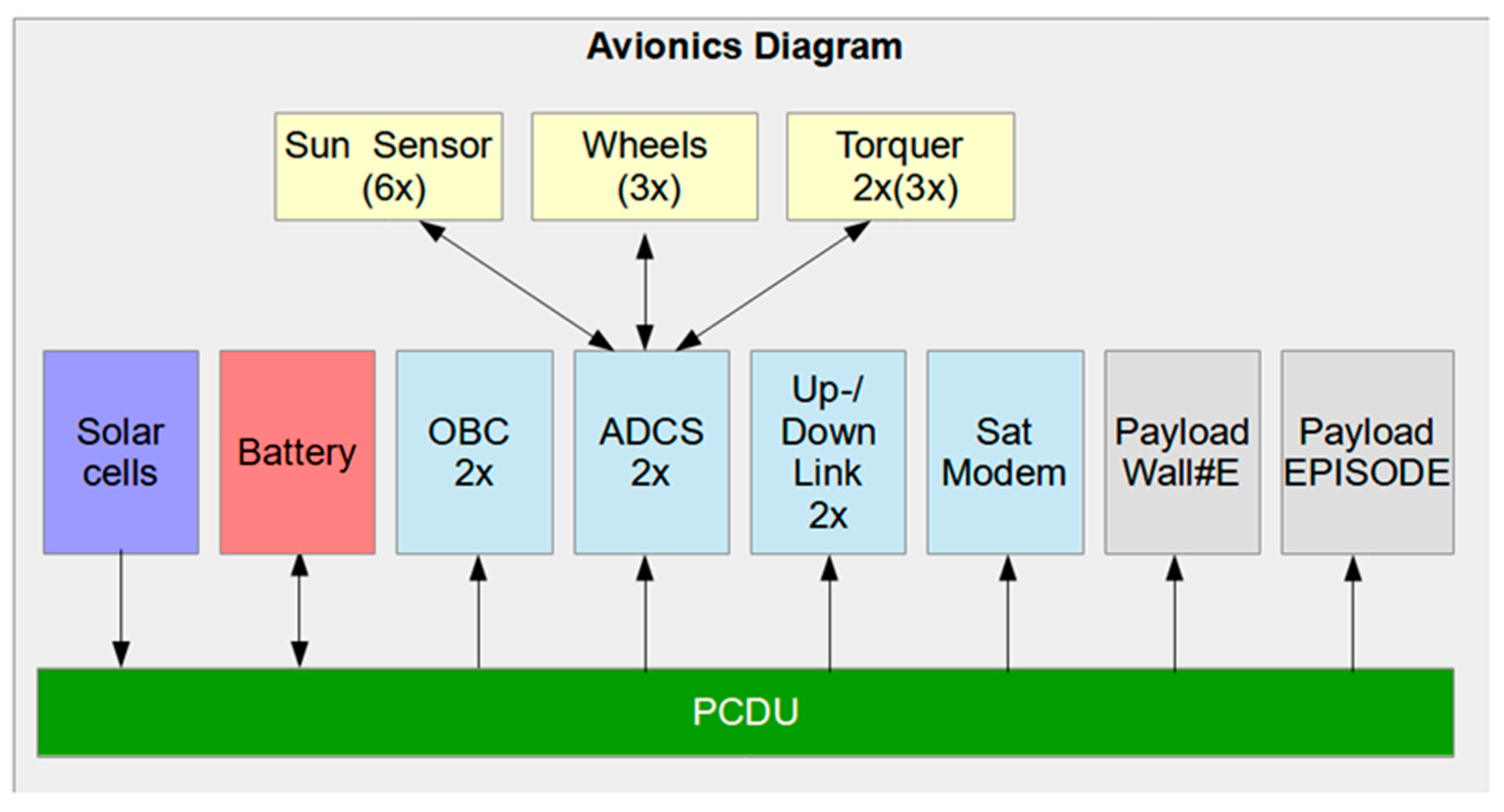
The ADCS is replicated twice. Aside from the common SKITH interface implementing the control algorithms, there are additional components e.g., two micro electro mechanical systems (MEMS) gyroscopes, two magnetometer and front-ends for torquer control. Complementary, an interface to the sun-sensors and the reaction wheels is integrated. Both ADCS modules are assembled on a single board, which is mounted in a self‑contained unit, holding the torquer and wheels. Further details are given in the corresponding subsection of the ADCS system.
The up-/down link transceivers for communication with the ground station are replicated to avoid a single point of failure. Additionally, a satellite modem is implemented, building a backup communication channel. The modular concept is not limited to the avionics system, complementing a modular structure, which is explained in the following chapter.

3.1. Modular Structure

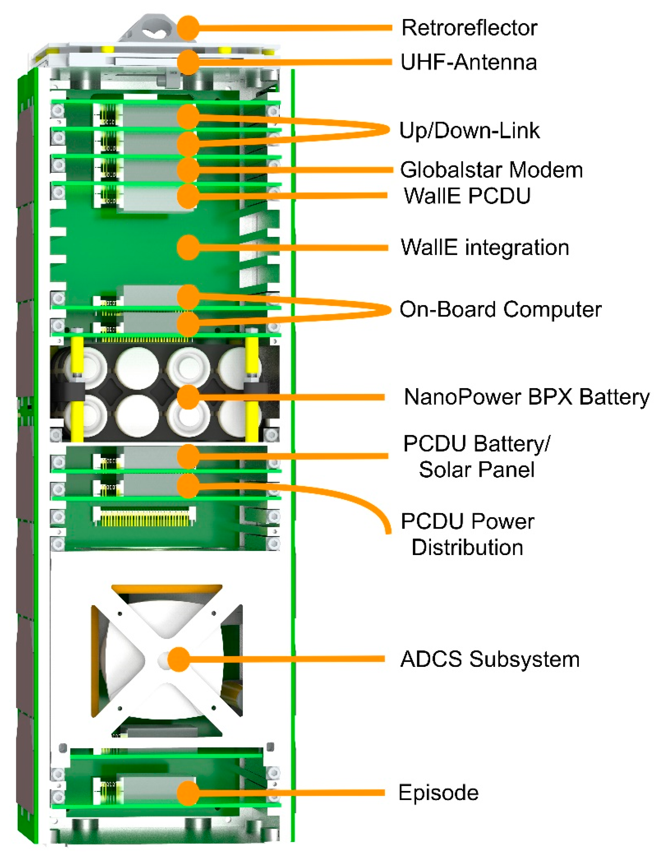
InnoCube is a 3U+ CubeSat (354 × 113 × 113 mm3) with a mass not exceeding 4 kg. One of the benefits of a wireless bus system is the lack of the data harness and the ability to test hardware in the laboratory as well as integrated in the satellite. To utilize those benefits, the structure is designed to allow quick access and exchange of subsystem modules, allowing for variable circuit board size, enabling COTS and custom designs, which provide a certain radiation protection for the wireless bus modules.
The structure concept is to install the subsystem circuit boards individually from the front with little assembly effort. For this purpose, boards can be inserted from the front on evenly spaced rails in the sidewalls with clamping mechanisms, wedgelocks, retaining each board in its inserted rail slot as shown in Figure 9. Wedgelocks are pin-shaped components that expand when tightened, building a resistance against the side of the rail and board. This way, the circuit boards are secured in place providing resistance to shock and vibration, as well as enabling a thermal transfer to the main structure. The power supply to the modules is realized with a backplane.

3.2. Thermal-System

In general, InnoCube’s thermal control design has to keep the satellite’s internal temperature at least within the range of −40 to +85 °C. This range derives from the extensive use of industrial grade COTS components for the internal electronics. External units (such as the sun-sensors) may be subjected to much more extreme temperatures and have to be considered separately later in the development process. The internal battery has more strict thermal requirements depending on its current operational state: Charging and discharging the Li-Ion batteries are constraint to a tighter margin in their operational temperature range in order to prevent damage or degradation. For the used Panasonic 18,650 cells charging requires 0 to +45 °C while discharging allows −20 to +60 °C, considering the anticipated charge and discharge currents provided by the power analysis [17].
Typically, CubeSat architectures already provide a reasonable passive thermal design baseline which can be optimized using suitable thermal coatings as finishes [18,19]. Since more than 85% of the external surfaces are covered by solar cell panels, these finishes are only applicable on the end faces and to some degree on the remaining structural elements. Because of the very low power dissipation of the selected integrated circuits and other electrical components, internal contributions to the thermal energy balance are anticipated to be relatively low. Notable contributions are only expected to be the ADCS actuator systems (magnetorquers and reaction wheels) as well as the UHF transmitters. Hence, placing the battery in the center of the satellite near the ADCS and Tx/Rx hardware is considered advantageous. However, moving the Up/Downlink hardware away from its current location at the end of the satellite near the antenna is currently unsuitable and has to undergo additional considerations. Therefore, using an active heating system in order to keep the battery in its thermal operation range is being considered. The selected battery pack already has an integrated autonomous heater system which will be used to heat the battery if necessary [11]. Thermal analyses with finite element methods (FEM) and the thermal analysis software ESATAN‑TMS (Thermal Modeling Suite) using the final design of the satellite has to be conducted in order to verify the given thermal condition later in the development.

3.3. Power

The power system is composed of three main components, i.e., a battery pack, solar panels and a PCDU. The purchased battery is designed for the use in nano-satellites and is composed of high-capacity lithium ion cells in a 2S-4P configuration with a total capacity of 10.4 Ah. It is equipped with a heater system, expanding the operational temperature range. The 3U solar panels, which are radiation and temperature resilient, consist of Azur Space 3G30A triple-junction solar cells with up to 30% efficiency, comprising a temperature and sun sensor. The PCDU is a contribution by the Institute of Space Systems of DLR Bremen and follows a new approach of high modularity, giving the ability to be tailored for different mission requirements by use of design automation techniques. It is set up to be fault–tolerant, due to redundancy and includes standard features as maximum power point tracking (MPPT) for battery charging or latch up protection of the outputs. It delivers 19 switchable output channels, one for each module on the satellite. The power system fulfils the power budget requirements see Section 2.3.

3.4. Attitude Determination and Control System—ADCS

Given a 600 km sun-synchronous LEO, InnoCube is expected to be subject to external disturbance forces lower than 10−7 Nm, not considering the satellites residual magnetic moment. It is hard to estimate the residual magnetic moment, but literature analysis expects it to be less than 0.1 Am2 for a typical CubeSat [20,21]. Considering 0.2 Am2 torquer rods allows for an active magnetic actuation with a maximum torque of 1 × 10
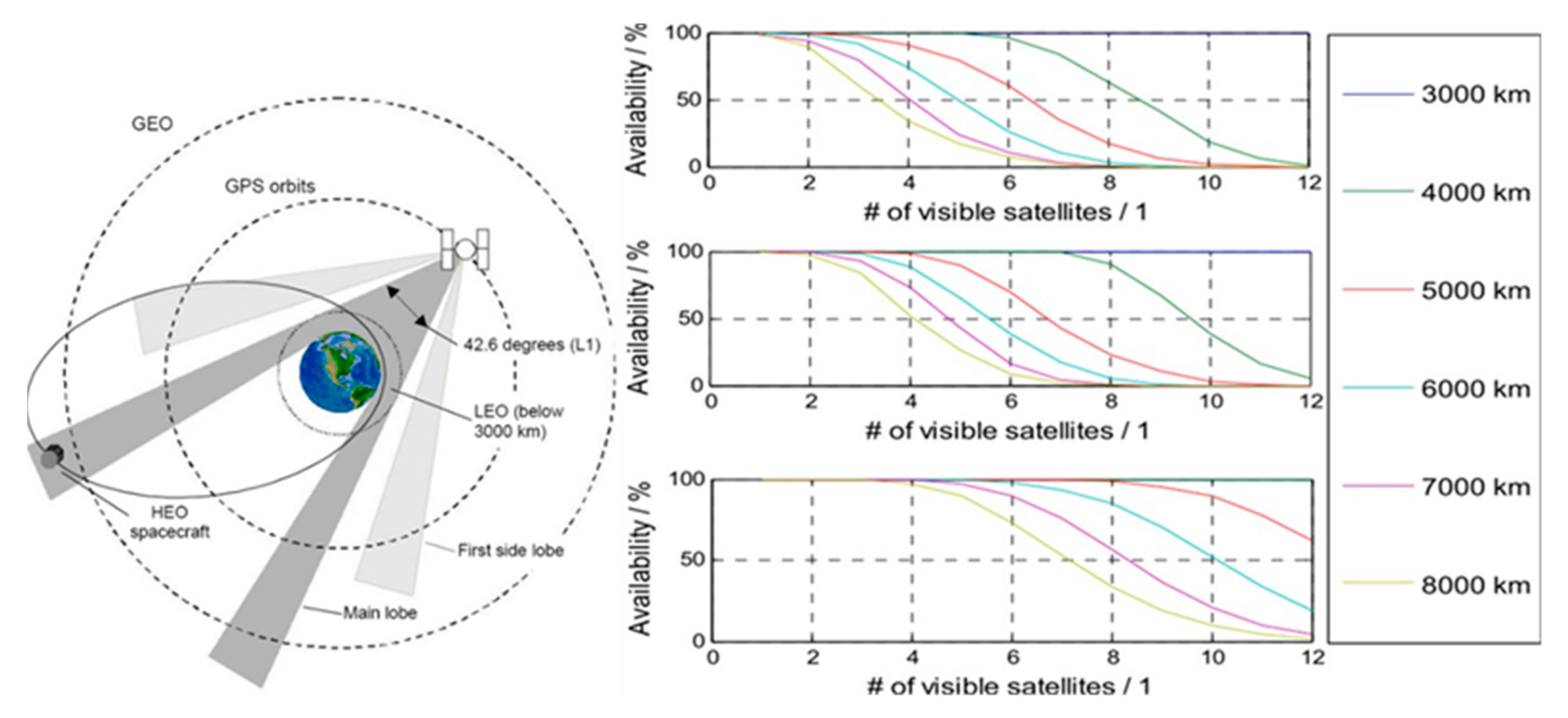
⁻⁵ Nm depending on the orbital position. System requirements imposed on the ADCS derive mainly from the EPISODE payload. The communication subsystem does not require specific attitude control because of the antenna’s omnidirectional characteristics. The EPISODE payload requires two main scientific attitude control modes: GNSS Antenna Pointing and Laser Ranging Ground Station Tracking. GNSS Antenna Pointing resembles an anti-nadir tracking, which ensures an unobstructed field-of-view into medium Earth orbit (MEO) of the GNSS antenna. Assuming a ±50 deg antenna beam width leads to a ± 130 deg anti-nadir attitude requirement. Assuming a 600 km circular orbit leads to maximum attitude of 3.75 deg/min for anti-nadir tracking. Laser ranging ground station tracking orientates the LRR in the direction of the laser ranging ground station and tracks this specific attitude. Figure 10 associates different contact elevation angles with required torque for optimum tracking performance. The LRR tolerates ±17 deg deviation from the optimum tracking orientation which is 20 deg off-axis pointing of optimum line-of-sight. With final simulation still pending, 2.3 mNm has been chosen to be the minimum torque requirement for the attitude actuation. In order to accommodate these requirements, a typical 3-axis ADCS will be implemented [18,19]:
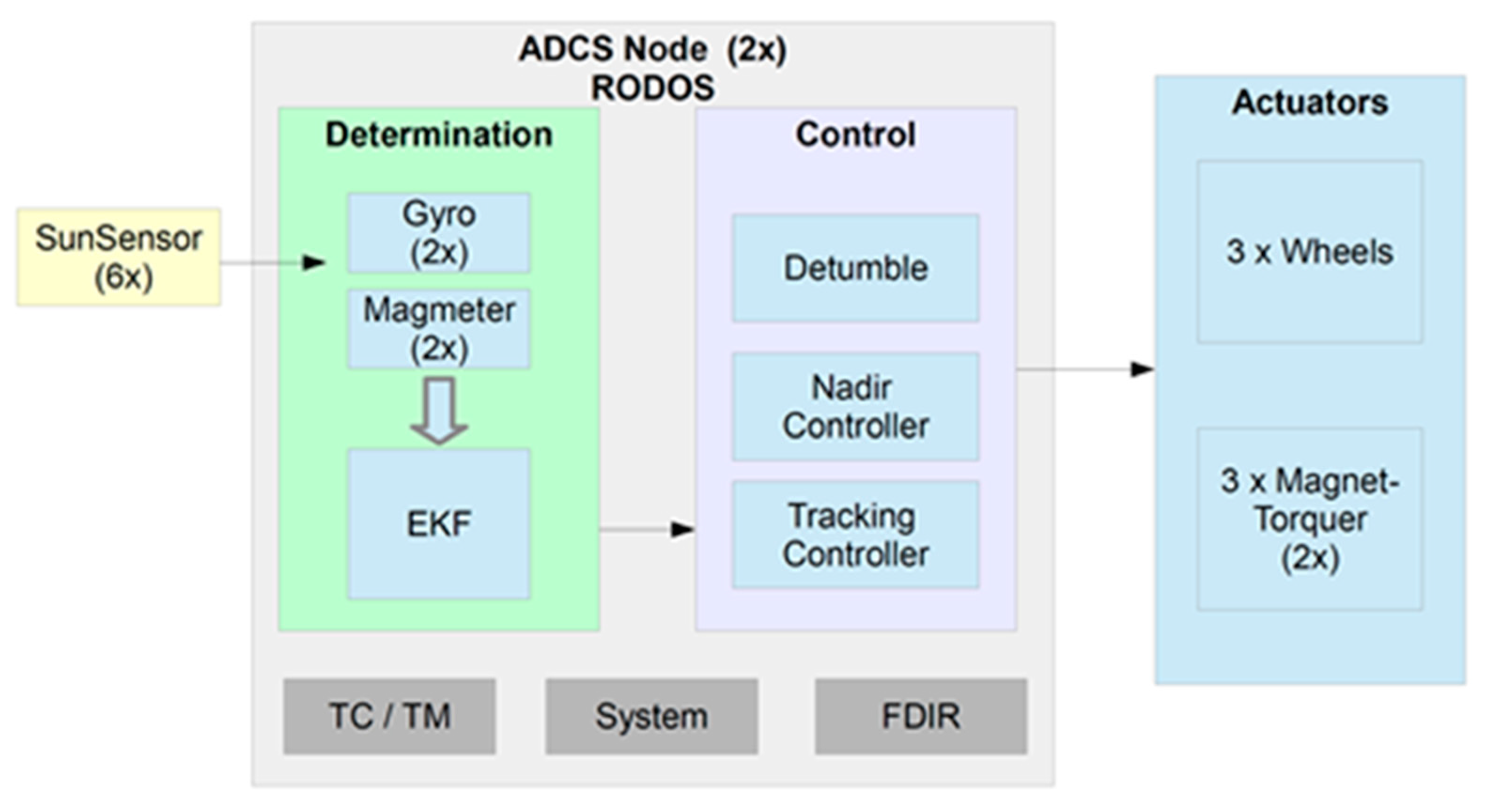
Figure 11 gives a basic system overview: attitude determination will be carried out using redundant magnetic and gyroscope sensors combined with six custom two axis sun-sensors, developed at the University of Wuerzburg. An extended Kalman filter will be used for sensor-data fusion and final attitude estimation. This allows an absolute attitude reference necessary for the attitude controlling as well as the estimation of the gyroscope biases. A yet to be determined quaternion feedback controller will serve for the nadir and tracking control laws. A basic B-dot bang bang detumbling controller can be used for the initial damping of the rotational rates as well as for possible desaturation of the wheels.
The low dynamic GNSS antenna pointing mode can be accommodated by the use of three magnet-torquer actuators only. The magnet-torquers will be based on a self-developed ferrite core torque rod. Because of the aforementioned minimum torque requirements, laser ranging ground station tracking requires the use of a three-axis reaction wheel actuation system. The magnet-torquers are utilized to desaturate the wheels if necessary. The ADCS software includes the telecommand and telemetry management as well as fault detection and isolation (FDIR) procedures.
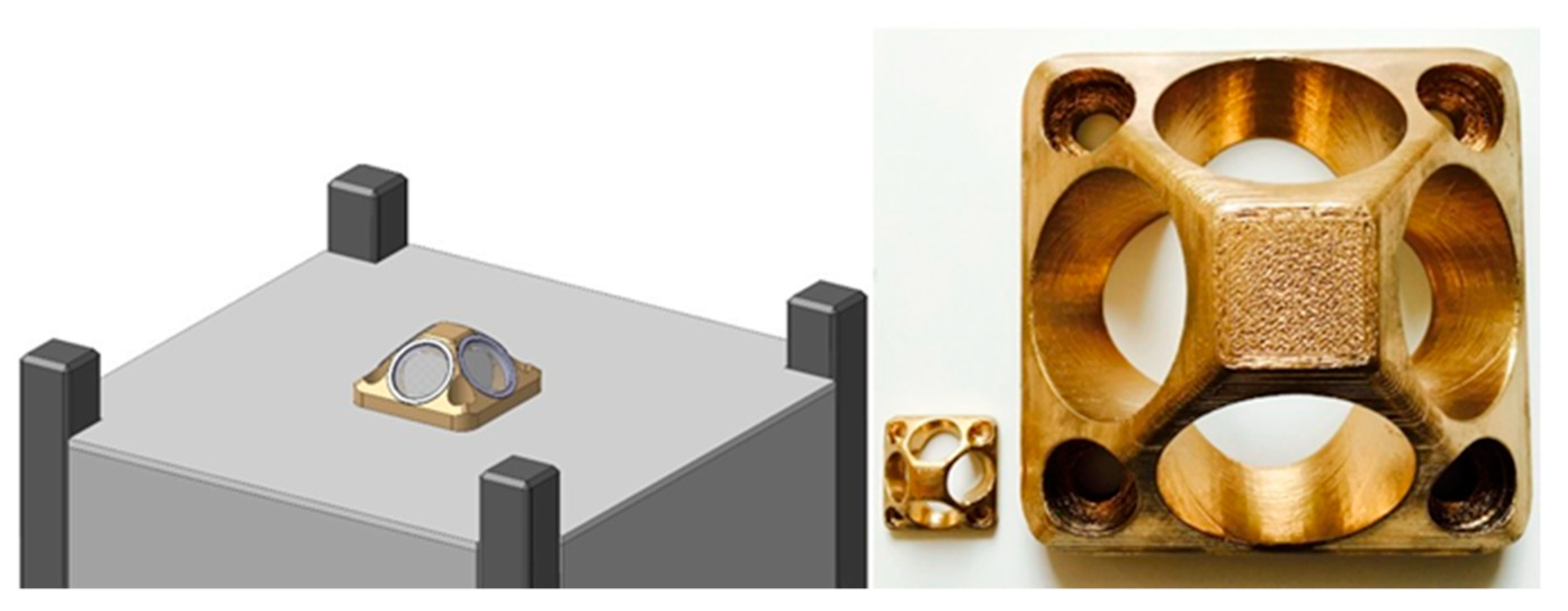
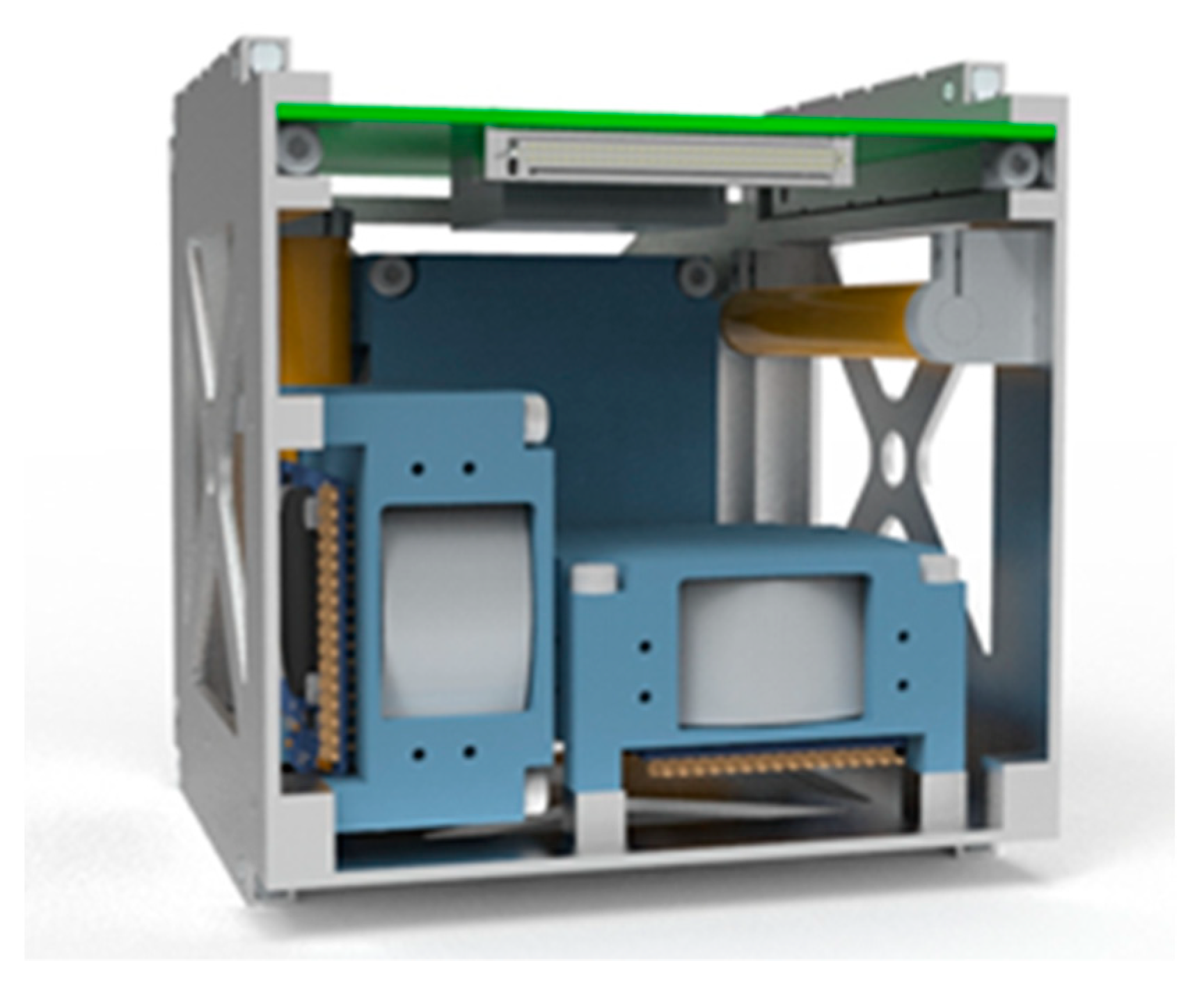
The ADCS hardware (except for the external sun-sensors) will be combined in a dedicated mechanical structure, which will subsequently be mounted inside the satellite. This structure also includes the ADCS mainboard along with the microcontroller running the ADCS software. The advantage of this closed-box design is the improved stand-alone testing capabilities without the need for a completely assembled satellite structure. Figure 12 shows the CAD-model (computer-aided design model) of the ADCS box which can be integrated into the satellite using the mounting wedgelocks on the upper and lower sides. The only electrical interface is the backplane-connector mounted on the mainboard.

3.5. Command and Data Management System

The data management system and all avionics consist of a network of redundant SKITH modules. The OBC is the central element, responsible for commanding, telemetry, surveillance, housekeeping, payload interfaces and power control. There are four instances of the OBC on the satellite. The software will be based on Rodos, as it offers the optimal support for distributed and redundant computing.

3.5.1. Onboard Computer (OBC) Hardware

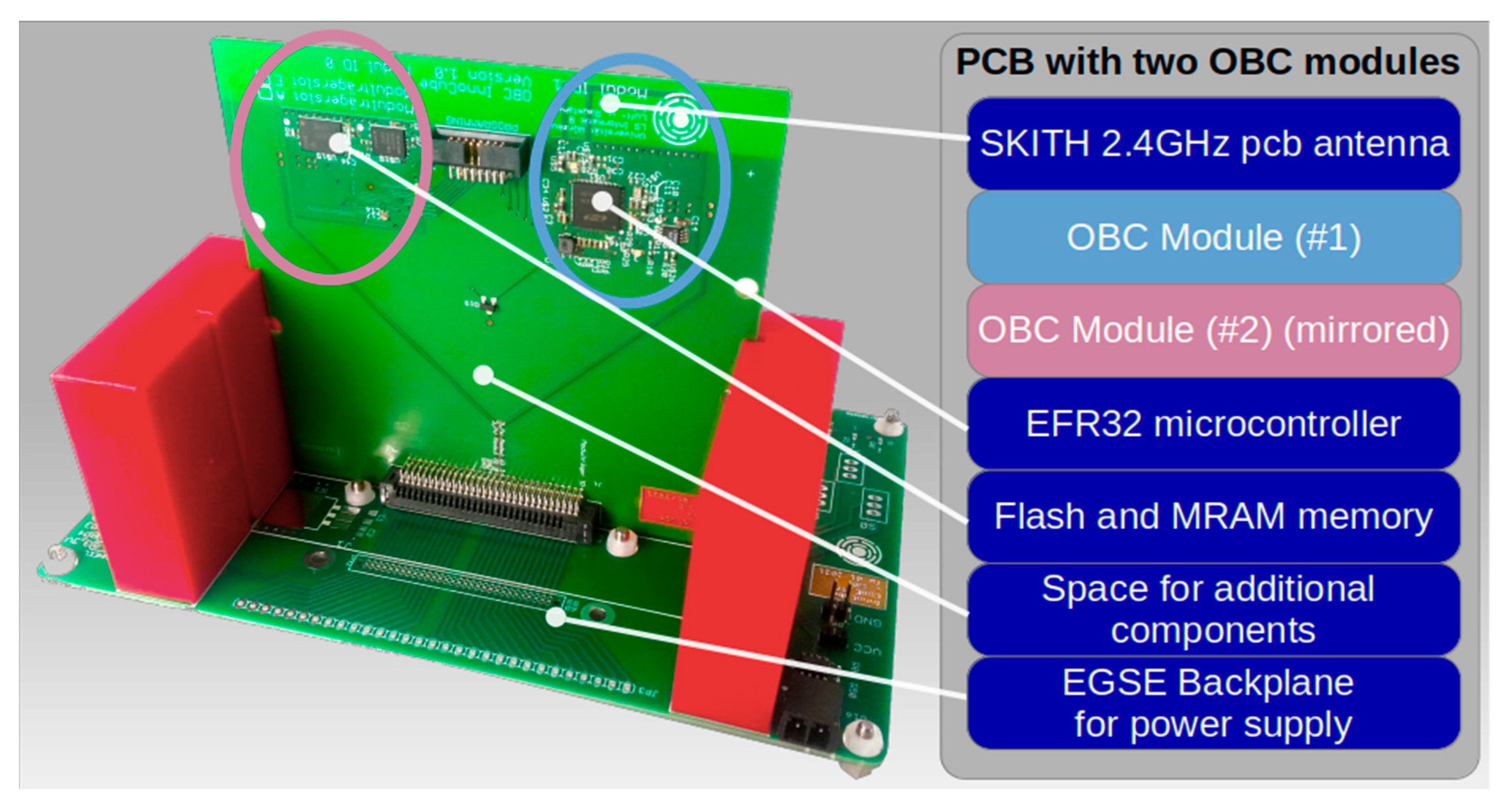
The OBC hardware is based on the SKITH interface, using the EFR32FG12 for both data processing and communication with other modules. Since the EFR32FG12 microcontroller is powerful enough for most applications, it will not only deliver the communication interface, but will also serve as a controller, handling sensors, actuators and memories. It implies a 40 MHz Cortex-M4 CPU with 1 MB flash memory and 256 kB RAM. A property that makes the EFR32FG12 perfectly suitable for a small satellite application is its low power consumption with a maximum power of just 36.3 mW while sending and 27.7 mW when receiving data over the 2.4 GHz interface. Additionally, the OBC is equipped with an external SPI 128MByte Flash and 1MByte MRAM, which have already been subjected to total-dose radiation tests.
Figure 13 depicts a PCB, carrying two OBC modules. The layout is identical for both modules, but mirrored due to thermal reasons. Since the PCB dimension is given by the mechanical structure, this layout offers an area for additional components.

3.5.2. Software

The SKITH hardware is designed in a modular way, having different modules for different tasks. For the software, the same modularity principle is used. Each SKITH module runs software with common tasks (e.g., housekeeping) and module-specific tasks. To address modularity in software, we follow an app-centric approach for the software design.

3.5.3. Onboard Software

The onboard software is based on two frameworks: Rodos and Corfu. Rodos is an open source operating system with flight heritage mainly developed at the University of Wuerzburg and the German Aerospace Center. It is able to run on different processors and platforms in bare-metal execution, but it also runs as a guest on other operating systems, such as Linux. For bare metal execution, Rodos comes with a real-time preemptive scheduling to adhere to timing requirements. A hardware abstraction layer allows to develop on a desktop computer and directly deploy the code to the target platform.
Besides the low-level part, Rodos comes with a sophisticated communication middleware. The middleware applies the publish/subscribe principle. Users instantiate topics, which publishers use to publish new data, and subscribers register for notification on data delivery. Beyond the local communication, the middleware comes with gateways that enable publishing and subscribing topics across several computing nodes (i.e., Rodos instances). Rodos middleware is used for exchanging messages via radio between the SKITH modules.
While Rodos provides the basic infrastructure for executing software on hardware and providing a communication middleware, the Corfu framework provides a common structure for onboard software. Developers define topics, apps, and nodes formally in configuration (specification) files. A node represents the instance of a software that runs on a SKITH module a selection of apps.
Apps are a collection of threads and subscribers that accomplish a specific task, for example housekeeping, attitude control, or time management. Each app defines a communication interface towards other applications and towards the ground segment. Developers describe the communication interface between the apps by defining which topics the apps publish to and which they subscribe to. The wiring of the topic publication and subscription is accomplished by the node.
The app interface towards the ground segment comprises a list of telecommands to which the app reacts and a list of telemetry that the app transmits. A special case is the standard (real-time) telemetry. While apps transmit normal (extended) telemetry only on request, the standard telemetry is transmitted periodically. The standard telemetry gives a quick overview of the node’s vital status. Therefore, every app should contribute some variables with the most important vital parameters.
Based on the information of the configuration files, Corfu generates code with abstract methods that the developers have to implement with their intended behaviour. Corfu already covers the communication handling—either in its library or in the generated code. Methods just have to be implemented that pass the parameters in a plain structure or invoke methods to send data.
To provide rapid prototyping of onboard software, Corfu also comes with a generic ground software. It uses the same information of the configuration files to show a graphical user interface for sending telecommands and printing telemetry data.

3.5.4. InnoCube Apps

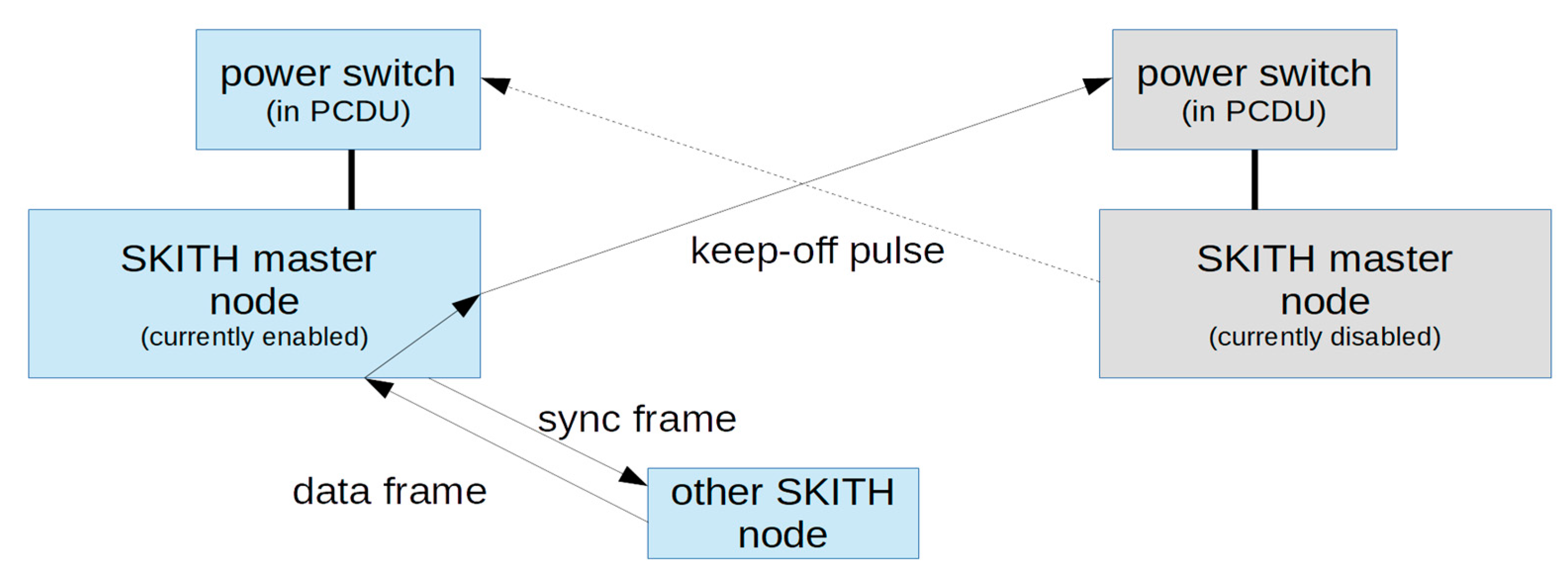
As outlined in the former subsection, all apps are developed in Corfu and each app can be configured to fit different nodes, before being compiled into a specific Rodos image. A set of vital apps are present on all nodes enabling basic overview and operations, e.g., the AnomalyReporter, Housekeeper, Surveillancer, and Watchdog, which are continuously monitoring and reporting on the state of each node. Furthermore, there are the apps needed to upload operating system images, write them to flash memory and boot the node, namely the FirmwareUploader, FlashManager and BootManager. Finally, there is always a TimeManager client present for CubeSat-wide time synchronisation. There are six different configurations of SKITH nodes that come with the following apps in addition to the vital apps mentioned above: The OBC node software features the Commander, which receives the telecommands sent from ground segment, verifies their signatures and publishes them to the Telecommand topic. The more complex TimedCommander stores and distributes lists of time-tagged commands, which can also be edited via telecommand before activation. Reacting on specific telecommand lists for certain satellite modes, the Navigation and PowerManagement apps issue high level commands to the SKITH nodes which are controlling the respective subsystems. The PCDU node image includes the BatteryVoltageManager, the PowerManagementExecutor implementing the commands issued by the PowerManagement as well as the RedundancyManager ensuring that only one of each hot redundant SKITH nodes is taking lead. In addition, this image comprises a MasterWatchdog and the SKITHRadioMaster, which issues communication frames to each node.
The up/downlink node is given the Uplink and Downlink apps needed to interact with the transceiver, as well as the DownlinkManager, which manages different queues of telemetry to be sent down and the TelemetryHistory app, holding older telemetry to be sent down when the link is otherwise unused. The attitude control node comes with the AttitudeDetermination and AttitudeControl apps, including the FDIR apps, which are explained in the ADCS section.
The payload computers for EPISODE and Wall#E will have dedicated apps to interact with each payload and forward the respective telecommands and telemetry.

3.5.5. Reporting and Command Flow

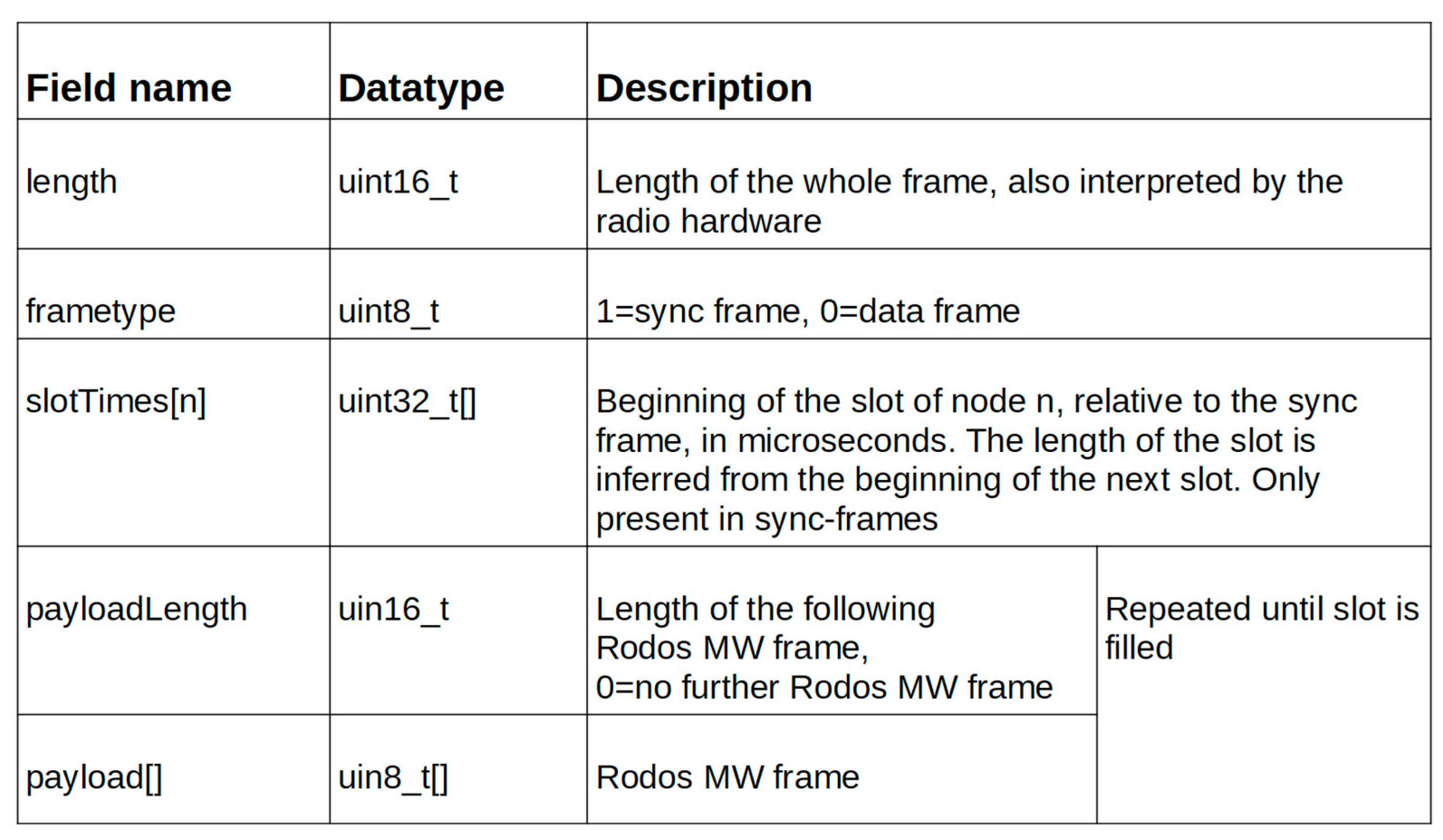
All SKITH nodes within InnoCube communicate over radio using the Rodos middleware on top of the radio protocol. The middleware topics and publish/subscribe mechanism provide a structured means of onboard communication.
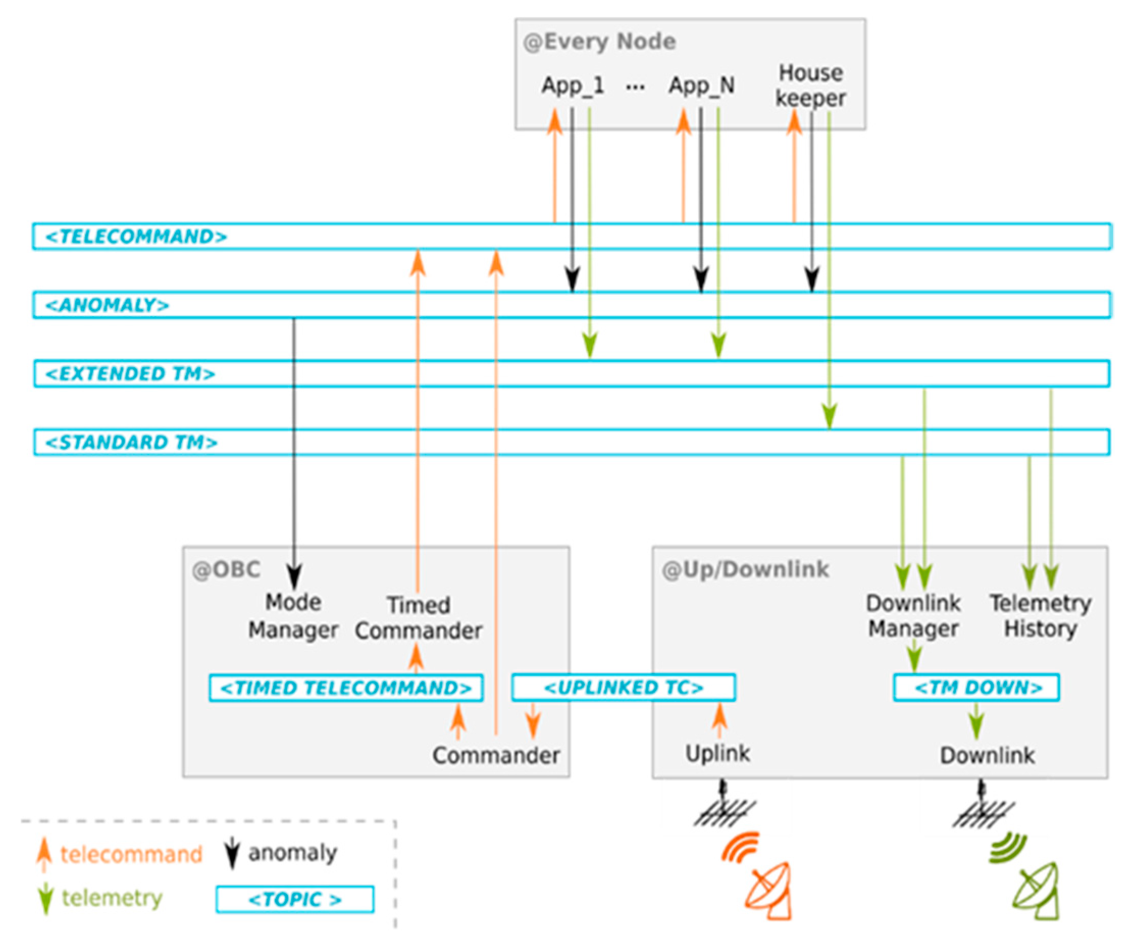
Figure 14 depicts the flow of information between the apps on InnoCube’s SKITH nodes as facilitated by the Rodos middleware: telecommands, depicted in orange, are sent from ground and received by the Uplink app, which publishes them to a topic only the Commander app on the OBC subscribes to.
After verifying the signature of the telecommand, the Commander publishes any telecommand to be executed immediately to the Telecommand topic. In case the Commander receives a timed telecommand to be executed later, it publishes it to the TimedTelecommand topic, from where the TimedCommander app retrieves and stores it. When the telecommand is due for execution, the TimedCommander publishes it to the Telecommand topic. All apps subscribe to the Telecommand topic and try to execute every command received via this middleware topic that was addressed to them and is formed correctly. Malformed or unknown telecommands are dropped by the app and a non-critical anomaly (black arrow) is published to the anomaly topic. If a severe error occurs, apps can also publish critical anomalies. The ModeManager on the OBC listens for anomalies and switches to safe mode depending on their severity. In save mode the TimedCommander publishes a set of telecommands from its save mode list to the Telecommand topic. There are two kinds of telemetry, both depicted in green: the standard telemetry of a node comprises of a set of telemetry of all of its apps that published periodically by the Housekeeper app to the StandardTelemetry topic. Extended telemetry can be enabled and published by telecommand for each app. Both the DownlinkManager and the TelemetryHistory app subscribe to the telemetry channels. The DownlinkManager schedules the telemetry to be sent down and forwards it via a node local topic to the Downlink app, which uses the transmitter to send it to ground. The TelemetryHistory stores older telemetry, which the DownlinkManager will try to schedule, at a lower priority, when the link is unused.

3.6. Communication

The main focus of the communication system is reliability and simplicity, as the technological demonstration of the satellite shall not be endangered by a failure of the communication link. The scientific data generated by the satellite consists of telemetry data and positional data, therefore high data rates are not necessary.
As first step of the design process, the frequencies for uplink and downlink are defined. The mission consists of education and technology demonstration. Consequently, amateur frequencies, which offer a number of advantages of a financial and organizational nature, are being used.
For simplicity and budget reasons, only one antenna can be included. As a result, only one band will be used as well: UHF frequencies in the range of 435–438 MHz.
The communication is performed by commercially available transceivers. A tradeoff lead to the selection of the RadioBro, MiniSatCom UHF transceiver. Although lacking extensive flight heritage, its size, power consumption, and configurability and comparably low cost lead to its use in the mission. With this product, two identical flight units can be integrated into the satellite.
A redundant configuration is implemented, with two identical transceiver units on separate boards. As both radios share a single antenna, a radiofrequency (RF) switch is used to change between the units. Multiple layers of internal identification are integrated to determine whether a transceiver is operable or not. Each of the transceiver boards additionally consist of two SKITH nodes, eliminating any single-point-of-failure.
The satellite design utilises only a single frequency antenna to avoid two antennas interfering with each other. As a result, the channel is capable of half duplex communication. Different configurations of antennas have been analysed, with regard to commercially available products and the UHF antenna module of EnduroSat has been selected. It represents a trade-off between cost, radiation pattern and deployment mechanism. The maximum gain is about 0 dBi, although the omnidirectional pattern is more important than its peak gain.

4. Conclusions Outlook

Aboard the InnoCube mission of TU Braunschweig and the University of Wuerzburg, the next level of innovative technologies will be flown. The first wireless satellite data bus using SKITH technology should provide numerous advantages that are utilized in the 3U CubeSat design. An easily accessible modular structure enables the switching of satellite modules within minimum time and, theoretically, in any phase of the project. Hardware and software are structured in a modular way, having different modules for different tasks and following an app-centred approach based on two frameworks: Rodos and Corfu. In addition, a novel experimental structural energy storage WallE-2-Space payload is to be tested and the performance analysed in a relevant operational environment. The development of a software-defined GNSS receiver that allows a flexible selection of GNSS signals should enable precise orbit knowledge for small satellites. This makes conjunction assessments more accurate, can prevent collisions, may help to stabilize the space debris environment and stimulates future research in this field. To verify the GNSS accuracy, a laser retro reflector is designed and scaled down to fit to a CubeSat system.
The upcoming steps are the manufacturing, integration, and test in the given timeline until the envisioned launch in early 2023 and verification of the technologies within the minimum one year in orbit operation. The upcoming challenges of this project are the detailed electronic board design and experimental charge regulation of the WallE-2-Space payload and finding the best integration scenario that minimizes the effect on battery performance. Furthermore, the SKITH modules need to be integrated into the circuit board design of the payload PCB and modules with COTS components. Finally, the software must be completed, especially the payload software and payload configuration app. All those tasks within this CubeSat project will create an attractive, practice oriented and practice relevant form of education for the involved students who will acquire specific technical knowledge and learn at an early stage to work in a team and result-oriented manner according to deadlines.

Author Contributions

Conceptualization, S.M., E.S. and B.G.; software F.S. and F.F.; formal analysis, J.-L.K. and M.T.; investigation E.D. and S.G.; writing—original draft preparation, B.G.; writing—review and editing, S.G., B.G., T.B., T.W., F.F., F.S., E.D. and E.S.; visualization, M.T. and J.-L.K.; project administration, T.W. and B.G.; funding acquisition, S.M. and E.S. All authors have read and agreed to the published version of the manuscript.

Funding

This work is supported (support code 50RU2001/50RU2000) by the Federal Ministry for Economic Affairs and Energy on the basis of a decision by the German Bundestag. We acknowledge support by the German Research Foundation and the Open Access Publication Funds of Technische Universität Braunschweig.

Acknowledgments

The authors like to acknowledge the great cooperation and work of the Avionics Systems department of Institute of Space Systems of DLR Bremen. Thanks to the Institute for Particle Technology (iPAT) of Technische Universität Braunschweig for previous and continuous cooperation and support with Wall#E. Further, the authors thank Ludwig Grunwaldt who provided the testbed and his expert knowledge for testing the prisms for the laser ranging payload at the GFZ Potsdam. Also, thanks to our sponsors Valispace and ITP Engines UK Ltd. for ESATAN-TMS. We further acknowledge the motivated students, who started to form the CubeSat group and are going to work and accompany us during this project until the launch and beyond.

Conflicts of Interest

The authors declare no conflict of interest.

References

  1. Braun, V.; Horstmann, A. Technical Report—Networking/Partnering Initiative TU-BS; ESOC (2011–2015); Institute of Space Systems: Braunschweig, Germany, 2015. [Google Scholar]
  2. Kebschull, C.; Braun, V.; Ströbel, R.; Stoll, E. Determining the influence on orbit prediction based on uncertainties in atmospheric models. In Proceedings of the 66th International Astronautical Congress, Jerusalem, Israel, 12–16 October 2015. [Google Scholar]
  3. Haak, U.; Hecker, P. Adjustments of a real-time software GNSS receiver for use on a medium earth orbit. In Proceedings of the 27th International Technical Meeting of the Satellite Division of The Institute of Navigation (ION GNSS+ 2014), Tampa, FL, USA, 8–12 September 2014. [Google Scholar]
  4. Moreau, M.C. GPS Receiver Architecture for Autonomous Navigation in High Earth Orbits, Dissertation. Ph.D. Thesis, University of Colorado, Boulder, CO, USA, 2001. [Google Scholar]
  5. Braun, V.; Gelhaus, J.; Kebschull, C.; Sánchez-Ortiz, N.; Oliveira, J.; Dominguez, R.; Wiedemann, C.; Krag, H.; Vörsmann, P. DRAMA 2.0—ESA’s space debris risk assessment and mitigation analysis tool suite. In Proceedings of the 64th International Astronautical Congress, Beijing, China, 23–27 September 2013. [Google Scholar]
  6. Gelhaus, J.; Kebschull, C.; Braun, V.; Sanchez-Ortiz, N.; Endrino, E.P.; Oliveira, J.; González, R. Drama final report-upgrade of esa’s space debris mitigation analysis tool suite. Tech. Rep. ILR/DRAMAIFR 2014, 1, 163–164. [Google Scholar]
  7. Celestrak Starlink TLE. Available online: https://celestrak.com/NORAD/elements/supplemental/table.php?tleFile=starlink&title=Starlink&orbits=0&pointsPerRev=90&frame=1 (accessed on 2 February 2021).
  8. Deshmukh, M.; Wolff, R.; Fischer, P.M.; Gerndt, M.F.u.A. Interactive 3D Visualization to Support Concurrent Engineering in the Early Space Mission Design Phase. In Proceedings of the Challenges in European Aerospace, CEAS Air & Space Conference, Delft, The Netherlands, 7–11 September 2015. [Google Scholar]
  9. EnduroSat. 3U Solar Panel. 2021. Available online: https://www.endurosat.com/cubesat-store/cubesat-solar-panels/3u-solar-panel-xy/ (accessed on 1 February 2021).
  10. ISIS. Solar Panels. 2021. Available online: https://www.cubesatshop.com/wp-content/uploads/2016/06/ISIS-Solar-Panels-Brochure-v1.pdf. (accessed on 1 February 2021).
  11. GOMSpac. NanoPower BPX Datasheet. 2021. Available online: https://gomspace.com/UserFiles/Subsystems/datasheet/gs-ds-nanopower-bpx-3-19.pdf (accessed on 6 April 2021).
  12. Plummer, C.; Planck, P. Spacecraft Harness Reduction Study; Vols. Tech. Rep. RE-01247-CP/009; Cotectic Ltd.: Overijse, Belgium, 2001. [Google Scholar]
  13. Silicon Labs. EFR32FG12 Gecko Proprietary ProtocolSoC Family Data Sheet. 2021. Available online: https://www.silabs.com/documents/public/data-sheets/efr32fg12-datasheet.pdf (accessed on 28 February 2021).
  14. Sinclair, D.; Dyer, J. Radiation Effects and COTS Parts in SmallSats. In Proceedings of the 27th Annual AIAA/USU Conference on Small Satellites, Logan, UT, USA, 10–15 August 2013. [Google Scholar]
  15. Grzesik, B.; Liao, G.; Vogt, D.; Froböse, L.; Kwade, A.; Linke, S.; Stoll, E. Integration of energy storage functionalities into fiber reinforced spacecraft structures. Acta Astronaut. 2020, 166, 172–179. [Google Scholar] [CrossRef]
  16. Liao, G.; Froböse, L.; Vogt, D.; Grzesik, B.; Linke, S.; Stoll, E.; Kwade, A. Integration of All-solid-state Electrolytes into Carbon Fibres for Development of Multifunctional Structural Batteries. In Proceedings of the 3rd International Conference on Battery and Fuel Cell Technology, London, UK, 9–11 September 2018. [Google Scholar]
  17. Panasonic. NCR18650B Lithium Ion Battery Datasheet. 2021. Available online: https://www.batteryspace.com/prod-specs/NCR18650B.pdf (accessed on 6 April 2021).
  18. Schwarz, T.; Balagurin, O.; Fellinger, T.B.u.G. SONATE—3U Nano Satellite Mission for Highly Autonomous Payloads. In Proceedings of the 4S Symposium, Sorrrento, Italy, 28 May–1 June 2018. [Google Scholar]
  19. Ley, W.; Hallmann, W.; Wittmann, K. Handbook of Space Technology; Ch. 8.4.4.6; Wiley: Chichester, UK, 2009; p. 702. [Google Scholar]
  20. Inamori, T.; Sako, N.; Nakasuka, S. Magnetic dipole moment estimation and compensation for an accurate attitude control in nano-satellite missions. Acta Astronaut. 2011, 68, 2038–2046. [Google Scholar] [CrossRef]
  21. Lassakeur, A. Investigation of the Magnetic Characteristics of CubeSats and On-Orbit Determination and Mitigation of their Dynamic Magnetic Moment Disturbance; University of Surrey: Surrey, UK, 2019. [Google Scholar]
Figure 1. left.: Global Navigation Satellite System (GNSS) in orbit reception geometry [4]; right.: Visibility of GNSS satellites in different orbital altitudes; top: Global Positioning System (GPS); Middle: Galileo; Bottom: combined [3].
Aerospace 08 00127 g001
Figure 2. Worst case power simulation.
Aerospace 08 00127 g002
Figure 3. Overview of the redundancy management.
Aerospace 08 00127 g003
Figure 4. Structure of implemented radio protocol frame.
Aerospace 08 00127 g004
Figure 5. Schematic structure of an energy-storing fiber composite structure (Wall#E) [13].
Aerospace 08 00127 g005
Figure 6. Steps that are necessary to achieve a navigation solution and tasks performed by an FPGA.
Aerospace 08 00127 g006
Figure 7. left: Cube Laser Ranging Reflector Experiment (LRR) exemplarily positioned on CubeSat top side; right: 3D printed CubeLRR reduced by approx. factor 4 with respect to the original sized (approx. 10 cm × 10 cm × 10 cm) Champ reflector holder.
Aerospace 08 00127 g007
Figure 8. InnoCube avionics overview.
Aerospace 08 00127 g008
Figure 9. Modular structure showing subsystem integration.
Aerospace 08 00127 g009
Figure 10. Example required torque for optimum pointing of different contact elevation angles.
Aerospace 08 00127 g010
Figure 11. Block diagram of attitude determination and control system (ADCS) subsystem.
Aerospace 08 00127 g011
Figure 12. Swappable ADCS box accommodating control electronics and actuators.
Aerospace 08 00127 g012
Figure 13. Overview of an onboard computer (OBC) module.
Aerospace 08 00127 g013
Figure 14. Telecommand, telemetry and anomaly flow between apps via the Rodos middleware.
Aerospace 08 00127 g014
Publisher’s Note: MDPI stays neutral with regard to jurisdictional claims in published maps and institutional affiliations.

