
Eeloscope—Towards a Novel Endoscopic System Enabling Digital Aircraft Fuel Tank Maintenance


1
DLR—German Aerospace Center, Department of Maintenance and Repair Technologies, Institute of Maintenance, Repair and Overhaul, 21129 Hamburg, Germany
2
DLR—German Aerospace Center, Department of Product Lifecycle Management, Institute of Maintenance, Repair and Overhaul, 21129 Hamburg, Germany
*
Author to whom correspondence should be addressed.
†
Current address: DLR—German Aerospace Center, Institute of Maintenance, Repair and Overhaul, Hein-Saß-Weg 22, 21129 Hamburg, Germany.
Aerospace 2021, 8(5), 136; https://0-doi-org.brum.beds.ac.uk/10.3390/aerospace8050136
Submission received: 31 March 2021
/
Revised: 29 April 2021
/
Accepted: 5 May 2021
/
Published: 12 May 2021
(This article belongs to the Special Issue Digitalization and Decision Support in Aerospace Maintenance Applications)
Abstract
:In this research article, a novel endoscopic system, which is suited to perform a digital inspection of the aircraft wing fuel tanks, is introduced. The aim of this work is to specifically design and develop an assisting system, called `Eeloscope’, to allow accessing and diving through an aircraft kerosene tank in a minimally invasive matter. Currently, mechanics often suffer from the harsh working environment and the arduous maintenance duties within the tank. To address such challenges and derive a tailored solution, an adapted Design Thinking (DT) process is applied. The resulting system enables a fully digital inspection and generation of 3-dimensional structural inspection data. Consequently, devices such as the Eeloscope will facilitate a more efficient and continuous inspection of fuel tanks to increase the transparency regarding the condition of hardly accessible aircraft structures and provide a work relief for mechanics at the same time.
1. Introduction
The fuel tanks of an aircraft represent safety critical components, since they inhibit explosive kerosene fuel. Defects within the fuel tank have led to several fatal accidents [1,2]. Accordingly, an efficient and safe aircraft fuel tank maintenance is a crucial process in aviation maintenance, repair and overhaul (MRO). Nevertheless, an aircraft fuel tank is currently associated with a highly manual and labor-intensive maintenance, as it is very hard to access and uncomfortable to work in for humans. Various safety precautions and preparation tasks such as the equipment of respirators must be performed beforehand. Although aircraft are generally filled with digital information and sensor systems, the MRO of fuel tanks is still lacking digital tools that support the maintenance staff in an adequate manner. In recent developments, aircraft manufacturers, airlines and MRO service providers introduced Digital Twins to leverage decision-making for maintenance aspects. Especially in the case of fuel tanks, those Digital Twins still lack inspection and repair data sources. Consequently, it is desirable to ensure a safe and comfortable working environment for mechanics and thus increase the process efficiency, digitization degree and decision support. Hence, a suitable solution addressing the above-mentioned problems and specific process requirements to enable a digital aircraft fuel tank maintenance is needed. Thus, this work aims to identify a tailored solution design and to respectively develop an assisting system.
Therefore, in Section 2 an overview of the aircraft fuel tank maintenance process and specific problems and requirements is given. Subsequently, the application of the design methodology used is described in Section 3. Within the approach, the current state of research and development (R&D) reveals the development needs of a specifically tailored solution. Using the concept of Design Thinking including problem understanding and solution ideation steps, multiple possible solution approaches for assisting systems are derived and discussed. The selected and developed assisting and inspection system named `Eeloscope’ is introduced in Section 4. Here, a detailed description of the newly designed concept and its subcomponents is given. The Eeloscope incorporates a novel locomotion approach that offers high maneuverability with an intrinsically explosion protected propulsion method. An initial experimental evaluation in Section 5 with respect to the motion and inspection capabilities proves the general technical feasibility of the approach. A discussion of the solution presented as well as an outlook on future potentials are given in Section 6.
2. Aircraft Fuel Tank Maintenance
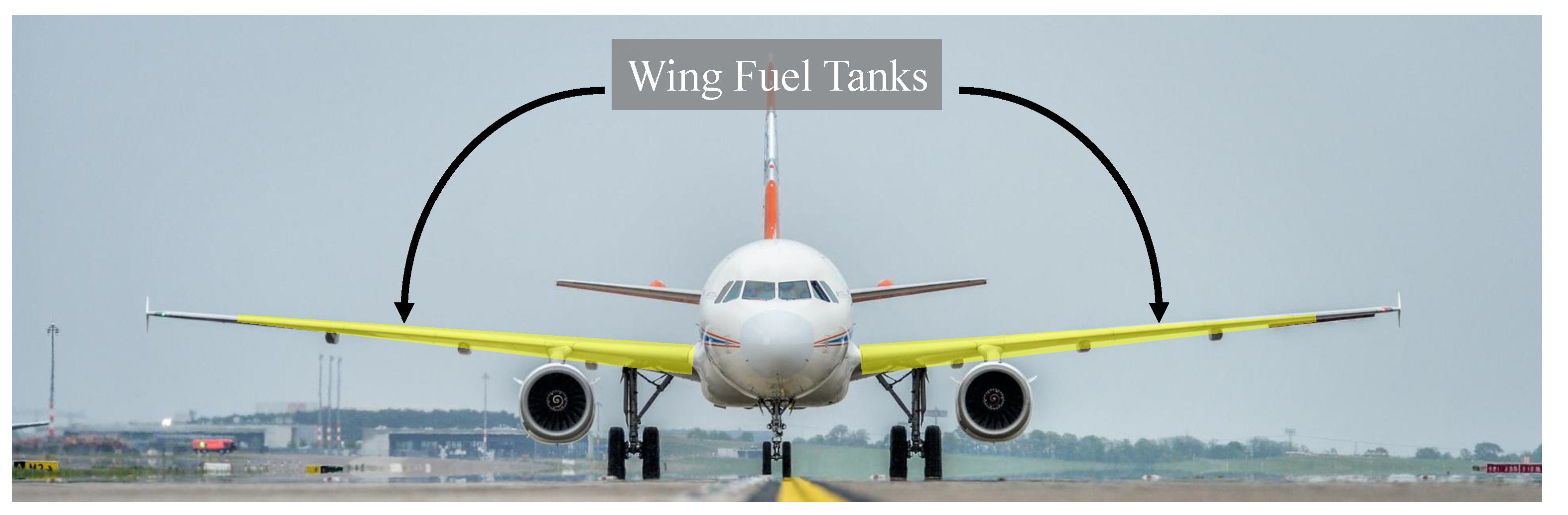
Commercial aircraft, such as the Airbus A320 displayed in Figure 1, hold multiple kerosene tanks. Specifically, those are the center tank within the lower fuselage, the left and right wing tanks and optional additional center tanks. Larger aircraft can also accommodate trim tanks in the rear fuselage section. The following subsections will provide an overview over the core functionalities, regulations, the maintenance process and resulting problems regarding the maintenance of fuel tank systems. This section will however set an exemplary focus on the wing fuel tanks.
2.1. Fuel Tank Functionalities
The core functionality is the storage of fuel, which will be fed to the engines. Underlying to this function, one can address four main requirements which are specified for example in the European Union Aviation Safety Agency (EASA) CS25—Certification Specifications for Large Airplanes document [3]:
- Leakage protection is clearly necessary to not run out of fuel during the flight, but also to not have kerosene dripping on flammable components such as the jet engine, which could easily lead to fire.
- Explosion protection is needed, since kerosene vapors and oxygen can bond to a highly flammable gas. This gas mixture can amplify risks from other defects in the tank, e.g., cable defects. It is, therefore, highly necessary to intercept these causal fault chains to prevent explosions, as in flight TWA800 [1].
- Structural strength is needed, since the wing can bend up multiple meters during flight maneuvers and carries most of the uplifting forces of an aircraft.
- Cleanliness is required since contaminations e.g., with water can lead to fuel clogging (icing in pipes) which eventually can lead to engine failure or wrong fuel level indication. Furthermore, microbe contamination can lead to corrosion [4].
The aircraft fuel tank system is a highly safety relevant component in the context of aircraft operation, not only during the flight, but also during ground operations (Thai Airways flight TG 114 accident [2]). As the tanks represent a crucial part of the airworthiness, the fuel tank system design, maintenance and training are regulated by authorities such as EASA or Federal Aviation Administration (FAA). Since multiple aircraft accidents in the 1990s had their root cause in defects within the fuel tank, airworthiness directives are aiming to improve the fuel tank safety. To remove potential ignition sources, the Special Federal Aviation Regulation 88 (SFAR 88) has been published by the FAA. The SFAR 88 also implied mandatory maintenance tasks that were included into the maintenance actions as of the advisory circular by the FAA [5]. The Fuel Airworthiness Limitations (AWL) describe the Airworthiness Limitation Instructions (ALI) that act as a guideline on how to inspect and maintain SFAR 88 related tank areas and components.
2.2. Maintenance Process
The act of maintaining the airworthiness of the fuel tank system is regulated by the national aviation safety agencies and is documented within the maintenance planning document (MPD) of an aircraft. In this research article, the Airbus A320 was chosen to be considered to be an exemplary aircraft type to illustrate the topic with factual maintenance instructions provided by the Airbus A320 MPD [6].
2.2.1. Basic Information
This subsection will provide an overview of the actual tasks that are performed during aircraft fuel tank maintenance. In the case of an Airbus A320, the demanded frequency for inspection is every 72 to 144 months according to the MPD. The main tasks concerning the fuel tank are the General Visual Inspections (GVI) and Visual Checks (VCK):
- GVI for Electrical Wiring Interconnection System (EWIS)
- GVI for minor external leaks
- GVI of internal tank wiring and probe attachments
- GVI for EWIS of vent surge tank
- VCK of vent surge burst disc (external)
- GVI of wiring harnesses above center tank.
The tasks listed above are defined in detail within the manufacturers aircraft maintenance manual (AMM), which also holds the specific job cards that are required to retrieve information about the actual execution of the task.
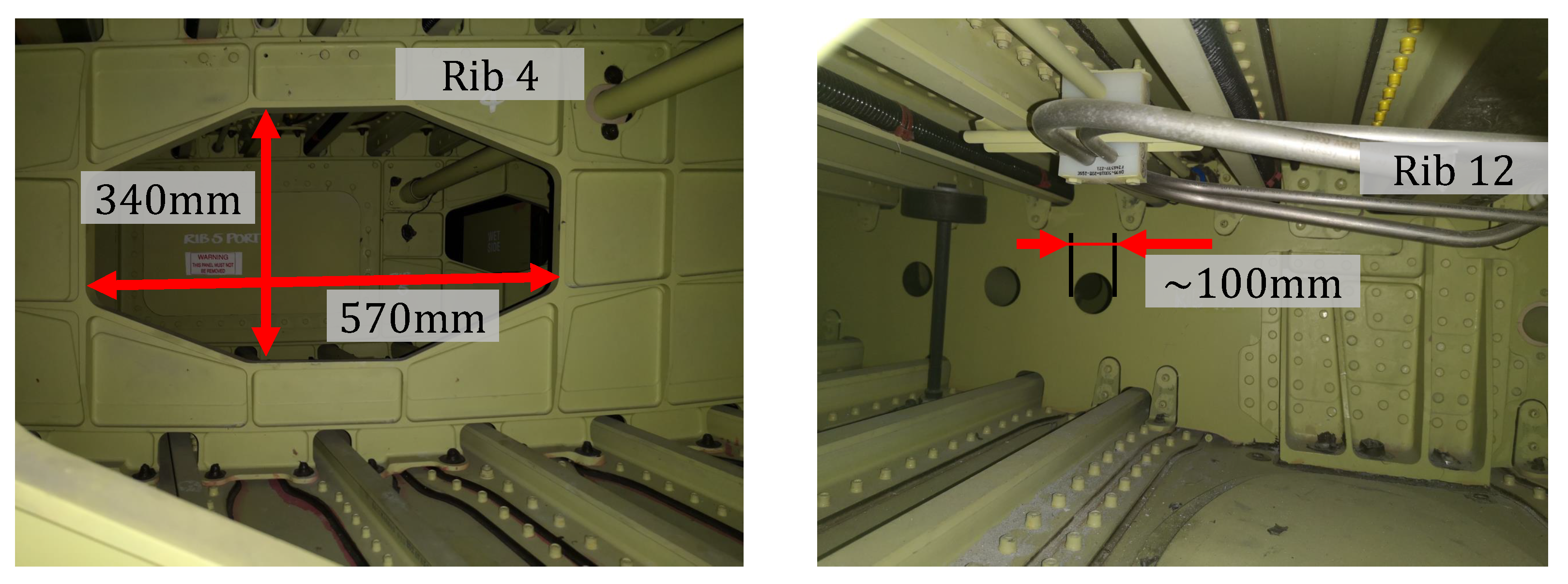
A detailed view of the structural environment of an Airbus A320 wing fuel tank is illustrated in Figure 2 with exemplary chambers from a fuel tank demonstrator at the Lufthansa Technik base in Hamburg, Germany. The left image shows a hole within the fourth rib of a tank chamber. Here, the MRO staff must crawl through to inspect or repair the tank. As can be seen, the manhole is just large enough for a grown human to traverse into the adjacent tank chamber since it does not have its own access hole on the lower site of the wing. This tank chamber lays relatively close to the fuselage, meaning the wing thickness is large enough for a human to fully enter the tank chamber. The right image shows a tank chamber at rib 12, which is closer to the wing tip. Hence, the thickness of the wing is too small for a grown human to fully enter the chamber. Effectively, the maintenance personnel can only reach into the tank chamber with their head and arms. Furthermore, some aircraft such as the Airbus A320 feature flapper valves between some tank chambers. These valves act as check valves and prevent kerosene flow within the tank chambers during rolling flying maneuvers.
2.2.2. Maintenance Process Description
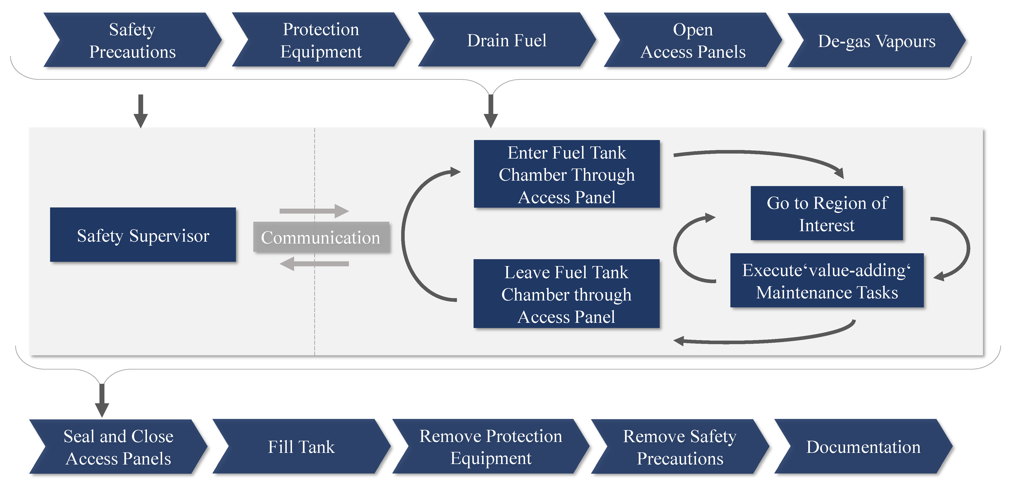
In Figure 3, the theoretical process chain for fuel tank maintenance is illustrated. The respective process information was derived from the AMM of an Airbus A320 and expert interviews with Lufthansa Technik. The context where the tasks are executed varies depending on the operating conditions. For commercial civil airlines, the tasks are usually executed within the context of a heavy check. Notably, these steps could in some cases be stretched over the whole period of a heavy check, which typically lasts four to six weeks. As of the MPD, the estimated time consumption for a GVI is around eight man hours for one aircraft.
At the beginning of a fuel tank maintenance process, several supporting preparation tasks must be performed. The specific safety precautions must be set up, for instance putting up warning signs, informing the fire brigade about conducting works in a fuel tank, de-energize the aircraft systems and locking the flaps with lock pin. Note that due to the de-energizing, no other functional tests of the entire aircraft can be conducted in the meantime. All internal tasks require the maintenance personnel to climb into the fuel tank. At the moment, no supporting tools or robotic systems are available that could take over the task. To protect against the existing hazards, the staff can be required to wear personal protective equipment (PPE), such as a cotton overall or gas mask. After draining the remaining fuel, the access panels can be opened to de-gas the fuel tank from vaporizing residual kerosene. When ventilating the tank, the AMM recommends testing the gas concentration for the first time after six hours. Accessing the tank is only allowed if the gas concentration is less than 10% of the lower explosion limit and the oxygen level is between 18% to 21%. Due to different ambient conditions and aircraft types, the duration of this process can vary. In the case of a heavy check, waiting periods can be used for different tasks in the meantime. However, in the case of only maintaining the fuel tank, this requires either longer waiting time or safer PPE such as gas masks. Entering the fuel tank without a gas mask requires continuous observation of the gas concentration with a gas sensor device.
To execute a complete maintenance process of the aircraft wing tanks, the mechanics must enter every tank chamber and perform the tasks listed in the manual. These activities represent the actual `value-adding’ tasks in the process. Throughout the whole process, a safety supervisor is needed to stand near the tank opening to keep a constant communication with the person inside the tank for safety surveillance reasons. Depending on national regulations, a so-called tank rescue cart is also used to hold various tools for emergency evacuation from the tank interior. The interior of a fuel tank is a very uncomfortable environment since there are many stringers and ribs present, resulting in a complex space. In addition to that, the tank is entirely dark and only illuminated through the access panel opening and by a torch from the mechanic. A further property of the tank is the presence of small residual vaporizing kerosene amounts. Since it is very hard to ventilate the whole tank, it can grow very hot depending on ambient conditions. To have a more comfortable workplace, mechanics often carry a rubber mat to sit on. Now, the mechanic can perform the required inspection tasks as defined in the manual. In the event of defect detection, repair actions must be considered. After the MRO actions are finished, the supporting post-processing tasks respectively closing procedure can be started. The most time-consuming task is the resealing and reassembly of all the access panels that were opened. Hereby, the mechanics must ensure that no leakages occur. This can be verified through filling the tank and observing the wing surface areas for visible leaks. After the tank is closed, the staff can remove their personal protective equipment and all safety precautions that were installed at the beginning. The whole process ends with a documentation of the performed MRO actions.
2.3. Major Problem Dimensions
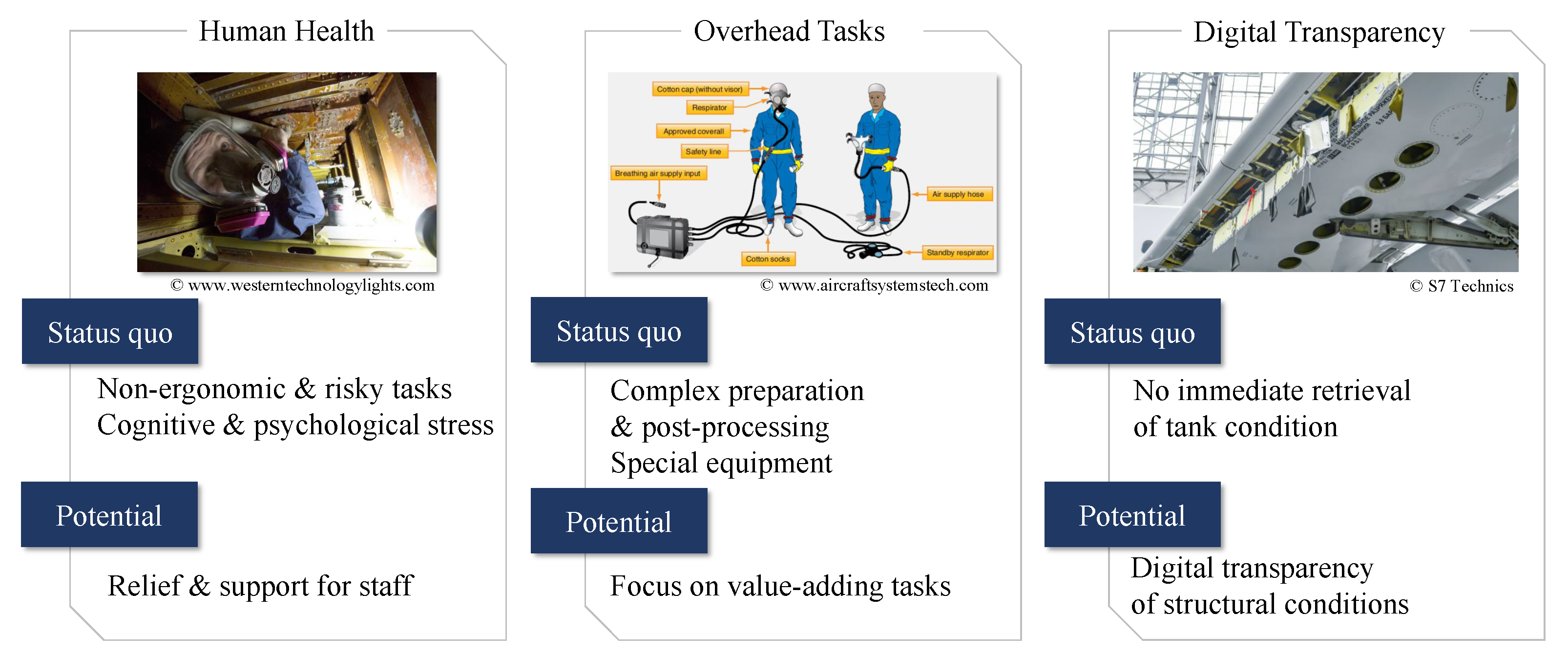
The problem analysis of the fuel tank maintenance process yielded three major needs as shown in Figure 4. The first problem dimension is the human health related aspect. As a working environment for the mechanics, the fuel tanks are inherently dangerous since residual fuel fumes are present (Effects from exposure to residual fuel fumes such as dermatological diseases or increased cancer probabilities are described in [7,8,9,10].). Additionally, the dark, narrow and uncomfortable environment can lead to stresses, as an interview with a former mechanic has shown. These influences can eventually lead to lower concentration levels during the arduous maintenance process and may result in overseeing defects. Thus, relieving the mechanics from these restrictions can increase the safety not only for the mechanics but also for the aircraft itself, since defects are more likely to be detected when the tasks are performed in a more comfortable and human-friendly environment.
The second problem dimension is represented by the high overhead that supporting process tasks and pre- and post-processing steps hold. To retrieve the current tank condition, many preparatory and downstream tasks must be performed. The maintenance staff spends a large amount of time in making the tank accessible for MRO tasks. This invasive approach also yields the risk of leakage after resealing the tank. Here, a focus on `value-adding’ maintenance tasks and activities is desired.
The third problem dimension addresses the lack of digital transparency. Currently, it is very hard to track the history of the tank condition. Additionally, the tank does not offer any reliable and consistent monitoring of its condition, as it is always closed and sealed. Offering for instance quick visual checks, to determine whether repair actions need to be carried out, can avoid unnecessary opening of the whole tank. As a result, digital maintenance and specifically inspection data would also enable state-of-the-art condition-monitoring approaches in combination with Digital Twins, as they are widely used in other aircraft parts such as jet engines [11,12,13].
As elaborated so far, the aircraft fuel tank maintenance process holds significant needs for novel assisting and decision support systems that contribute towards a digital MRO application.
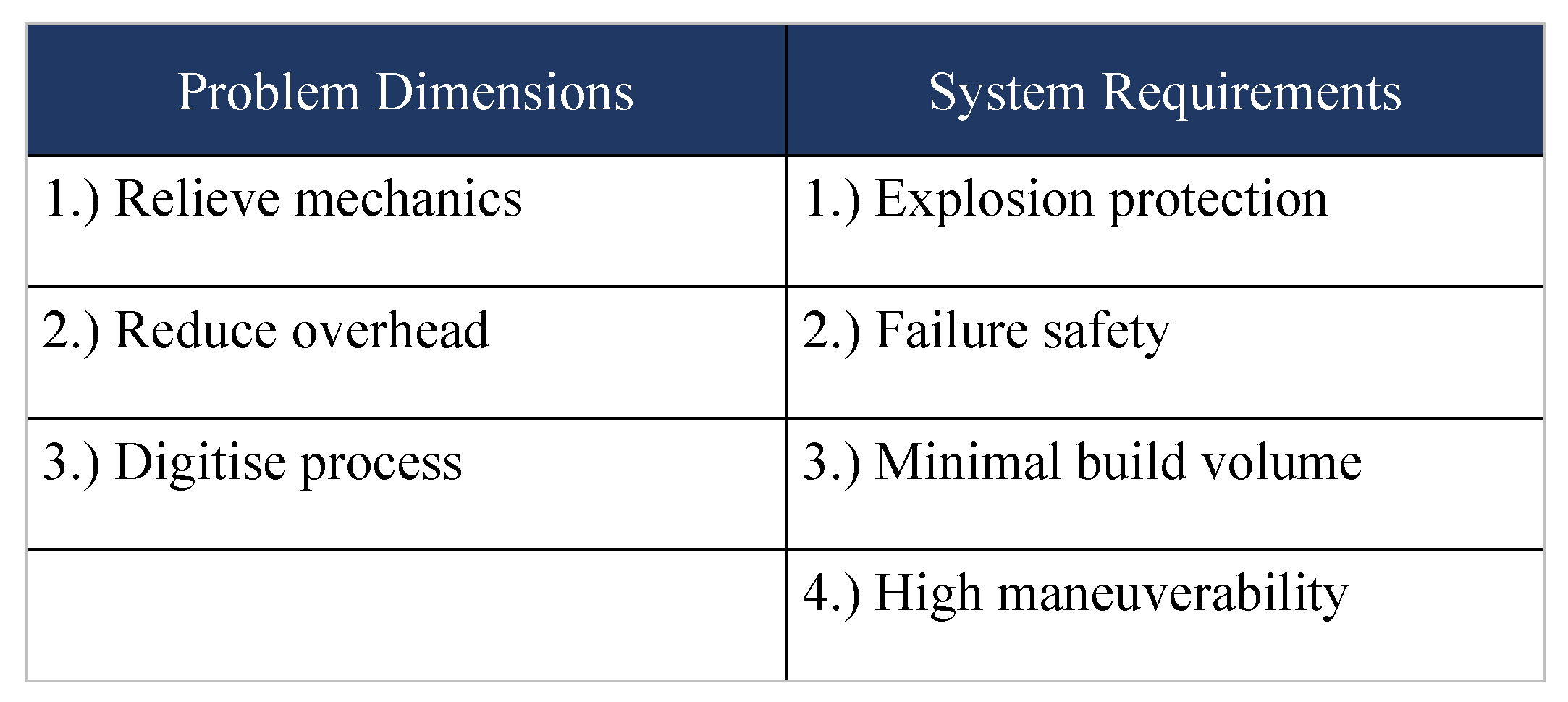
2.4. Specification Sheet Definition and Requirements
As a consequence of the previously mentioned needs, this section will define specifications and requirements that a respective assisting system should provide to overcome the existing problems. As of Figure 5, the specification sheet was divided into the problem dimensions of the existing maintenance process and the system requirements that apply to the novel assistance system.
The first goal is to relieve the mechanics from the harsh environment as much as possible. The staff should only spend a minimum amount of time within the tank and rather have a comfortable and safe working place, where it can focus on the actual important tasks. Regarding the design and development of such an assistance system, a major goal is also to reduce the complexity to access the tank interior, as it currently requires much time and labor-intensive preparations. To allow digital consistency, the developed system must allow the generation of digital inspection and repair data to improve the transparency and decision-making process. This will open the space for data driven maintenance planning approaches. As a second main requirement, the assistance system must be explosion protected as the surrounding kerosene, either as liquid paraffin or through residual vapors, is explosive. Additionally, a failure analysis should incorporate the possibilities for a quick removal or evacuation in the case of an emergency. Regarding the operational requirements, the system should be able to inspect the entire tank interior. Therefore, it should be possible to obtain maintenance respectively inspection data from any area in the fuel tank. Furthermore, the system should desirably hold a high usability together with a manageable system complexity to reduce investment costs since the process has a relatively low frequency.
For the purpose of an assisting system addressing the aforementioned problems and requirements towards the facilitation of digital aircraft fuel tank maintenance, suitable solutions need to be specifically designed and developed.
3. Design Methodology
3.1. Design Thinking Approach
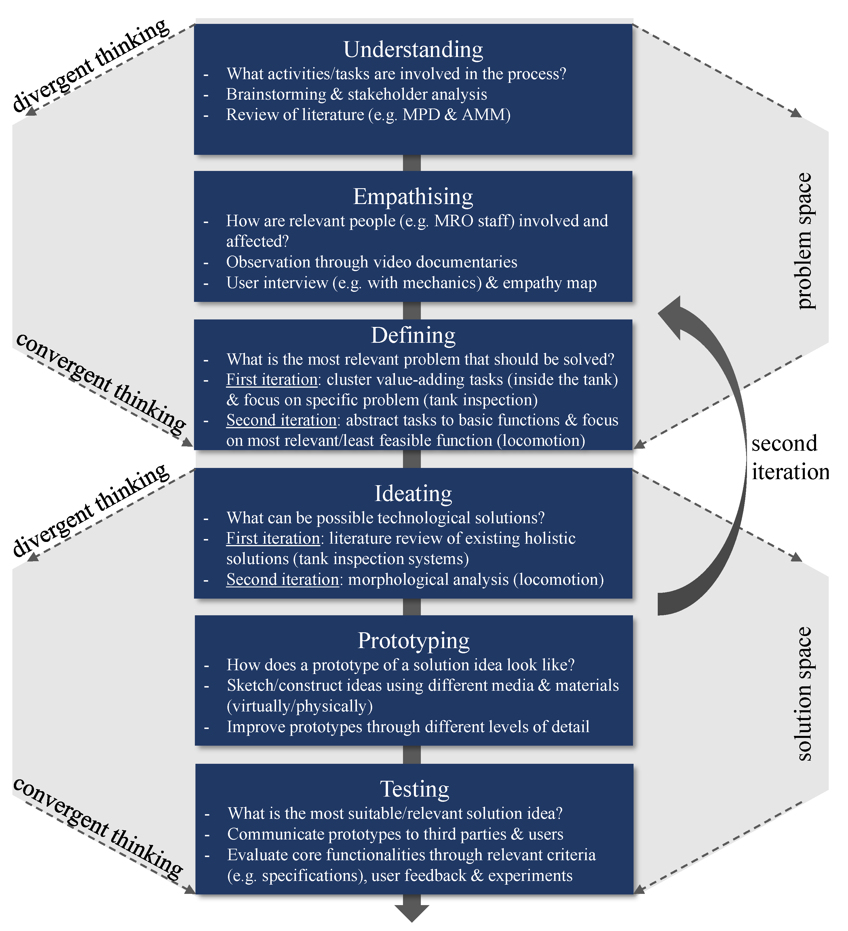
As the overarching objective of this work is to address relevant problems towards digital aircraft fuel tank maintenance through the development of tailored solutions, a corresponding methodical and structured guideline is essential. Thus, an approach was adopted based on the process of Design Thinking, which describes a user-oriented, multidisciplinary framework for achieving desirable and innovative products iteratively through problem and solution stages [14]. Among innovation frameworks such as the stage-gate process or the V-model, the concept of DT generously provides various methodical possibilities for creative collaboration and learning in uncertain and complex environments. Therefore, a respective six phase procedure based on the DT model of the Hasso–Plattner Institute was applied while using different methods and techniques in each phase [15,16]. By considering this basic model, a structured but adaptable and dynamic framework leading to innovative solutions was expected.
Although the first three phases concentrate on exploring the problem space of the underlying topic, the last three phases are dealing with the solution space and respective alternative ideas. In particular, Lindberg et al. [17] emphasize here the need for an iterative alignment of both spaces to ensure design suitability. To support this, each space distinguishes between divergent and convergent thinking [18], meaning that both spaces involve an open exploration of alternatives before respectively focusing on certain use cases or ideas [17]. The overall structure of the approach applied in this work is shown in Figure 6 as a simplified display. In practice, the approach is being applied strongly iteratively with several loops between the above-mentioned phases. The design approach begins with the phase Understanding, where relevant information (e.g., maintenance tasks and regulatory boundary conditions) about the current fuel tank maintenance process are gathered. During the phase Empathizing, the process is qualitatively examined from the perspective of the MRO staff (e.g., mechanics) and their physical and emotional involvement and needs in performing the tasks. The stage Defining concludes the problem space by synthesizing the gathered process data and determining the most relevant problem or task to be focused on during the next steps. Subsequently, the solution space is opened by the Ideating phase. At this point, an exploratory and creative identification of possible technological solutions or ideas across various disciplines takes place. The phase Prototyping addresses the transfer of solution ideas into first virtual or physical prototypes. To concentrate on the most promising approach, the Testing phase converges the solution ideas through evaluation of the respective prototype potentials. The presented application of this procedure can be basically summarized in two iteration loops, which will be further discussed in the following subsections.
3.2. First Iteration Loop
3.2.1. Problem Space
To initially understand the procedures involved in an aircraft fuel tank maintenance process, various information sources were used to generate a comprehensive process chain. With this intention, a first brainstorming helped to identify relevant stakeholders and roles involved in the process, such as the maintenance mechanics and planner, the aircraft owner, the manufacturer, safety officers, aviation authorities and external experts. For the purpose of mapping the MRO process, a focus on the activities performed by the maintenance mechanics was set.
With a literature review in the field of fuel tank maintenance, those activities could be identified, leading to the process description in Section 2. Sources such as the MPD and AMM were of high importance here, since they provided detailed organizational (e.g., time related) and technical (e.g., specific equipment) information regarding the preparation and performance of tasks by the mechanics. Furthermore, expert interviews with Lufthansa Technik in Hamburg, Germany provided helpful insights. Consequently, it was found that the tasks in a fuel tank maintenance process can be generally classified as inspection (’sense’), repair (’act’) or supporting tasks.
During the phase Empathizing, the observation of video documentaries through the public internet led to more insights concerning the whole process and crucially contributed towards a more profound and diverse problem understanding based on the emotional needs and feelings of the mechanics. Furthermore, a user interview with a former fuel tank maintenance mechanic, who used to perform such tasks inside a tank for decades, was carried out to better understand the difficulties and clarify questions. According to the video observation and user interview, an empathy map was filled with statements concerning the emotional and sensual perception during fuel tank maintenance activities.
Based on the collected and observed findings three basic problem dimensions, namely the human health related aspect, the high overhead of supporting process tasks and the lack of digital transparency were derived (see Section 2). Accordingly, a focus on the tasks performed inside the tank (e.g., `inspecting/repairing cables’ rather than `equipment of respirators and tools’) could be set during the Defining phase. By this differentiation of actual `value-adding’ tasks from supporting (pre- and post-processing) tasks, the concentration on a relevant and specific maintenance problem was enabled. In particular, the problem definition was set on the tank inspection activities since they typically reflect the very first MRO activity, even before any repair steps can be taken. Moreover, inspection tasks represent most planned maintenance operations (for the example of Airbus A320 [6]). As a result of the first iteration of the problem space exploration, a focus on fuel tank inspection was achieved.
3.2.2. Solution Space
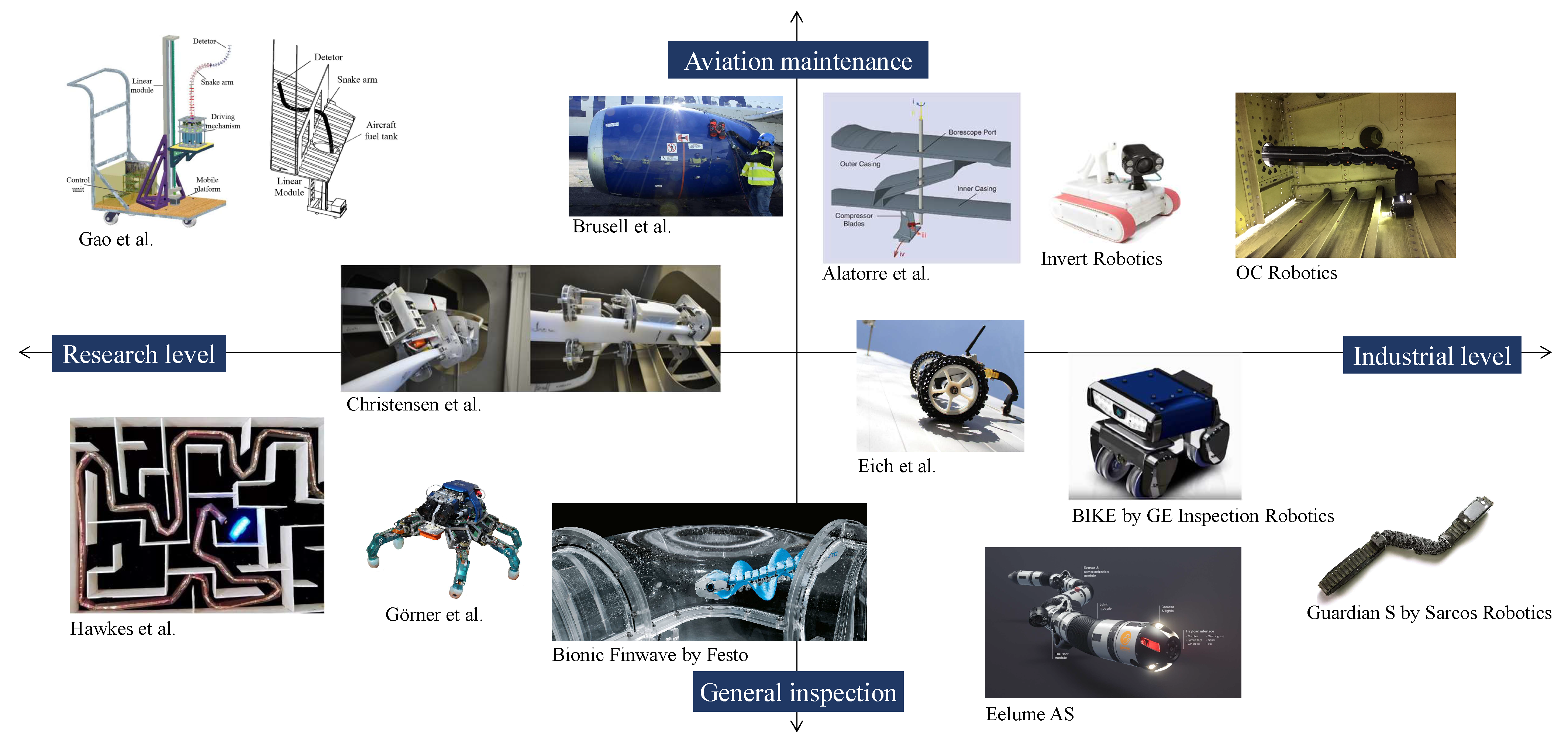
To identify possible technological solutions for the aforementioned problem statement, a technology scanning was carried out in the form of a literature review for robotic inspection systems in general. With this term, interdisciplinary solutions from various sectors were included to ensure an open and divergent Ideating. The goal of this approach was to broadly scan and explore the existing state of R&D for this or similar issues as a first basis of potential solutions that could aid fuel tank mechanics and MRO planners in their work.
Therefore, the technology scanning was clustered into two dimensions, as can be seen in Figure 7. On the horizontal axis, the systems are classified regarding their technology readiness level (TRL) to illustrate whether a technology would be available in short term or is still in an early stage of research. The vertical axis is instead displaying the intended use and distinguishes between aviation specific inspection systems and general industrial inspection applications. This overview provides only a subset of all the existing systems. The upper right section is considered to be the most relevant area, with systems that could potentially support the maintenance process. Here, the work from Anscombe et al. [19] of OC Robotics is very promising, since they designed a continuum robot for use in aircraft wing production and inspection. Continuous or hyper redundant systems are particularly good for aircraft wings, as this environment is very narrow and holds challenging conditions to avoid collisions while moving. Specifically, the work of Gao et al. [20] is addressing the process of aircraft fuel tank inspections, while also making use of a continuum robot structure. In contrast to OC Robotics, this work holds a comparatively low readiness level. A further robotic inspection and repair system was developed by Alatorre et al. [21] and Wang et al. [22]. Here, a continuum robot structure is used for in situ repair of jet engine turbine blades. In addition to the field of aircraft inspections, Brusell et al. [23] and Invert Robotics have demonstrated robotic application regarding exterior inspections. A rather novel approach was developed by Hawkes et al. [24]. This research group is developing vine-like robots that locomote through growth. This approach yields a high degree of maneuverability even in hardly accessible areas, due to its flexible shape. Bionic inspired systems such as the Finwave [25] were introduced by the Festo company. This fish-like system can dive through pipes for inspection purposes. Within the project of Christensen et al. [26], the use case of ballast tank inspection for large ships was considered. As a solution, they introduced a rail guided system that is routed through the entire ballast tank to reach any area within the tank. Commercially available solutions such as the crawler BIKE from Waygate (formerly GE Inspection Robotics) [27], the diving system from Eelume AS [28] and snake robot from Sarcos Robotics [29] are mainly used for inspections in the oil/gas and infrastructure sector. Furthermore, current research is also developing systems such as crawlers from Eich et al. [30] or Görner et al. [31]. These systems are more focused on the locomotion aspect but could potentially be fitted with sensors.
The scanning results indicated the existence of various systems in the context of robotic inspection systems, including aviation, shipping or petroleum industry and ranging from research level to `ready-to-use’ solutions. Indeed, the research revealed that the approaches found were strongly heterogeneous, implying different functionalities with specific technical characteristics, for instance in terms of power supply, mobility or sensors. Apparently, none of the presented systems sufficiently satisfied all process-based system requirements and problem dimensions set up in Figure 5 in the previous section. Notably, the explosion protection, high maneuverability and minimal build volume turned out to be very specific and difficult to meet. Each system would have implicated severe process limitations and development efforts associated with a restricted extensibility. Nevertheless, some identified approaches contained promising characteristics that could potentially inspire a tailored solution design. In particular, the example of the functionality `mobility’ included possible expressions such as stationary invasive (e.g., OC Robotics), mobile (e.g., BIKE), minimally invasive (e.g., Hawkes et al.) and in situ (e.g., Bionic Finwave). To be able to systematically consider and evaluate such expressions for a dedicated solution design, the initial problem statement needed to be further specified with respect to underlying functions that are of utmost priority for a first tank inspection prototype. Thus, a second Design Thinking iteration through problem and solution space was required to be carried out.
3.3. Second Iteration Loop
3.3.1. Problem Space
For the purpose of a more detailed specification of the problem statement, the second iteration of the problem space concentrated on the phase Defining. Therefore, the aforementioned value-adding inspection activities from the process description in Section 2 were viewed in terms of their basic functions (‘What is the functional aim of this step?’). Hence, an abstraction of the particular inspection process steps, which need to be performed inside the tank by a human or system, was undertaken. Each of these required functions represented a certain feature or capability, which would have had to be addressed by a potential solution. Subsequently, the resulting basic functions were assessed by the authors regarding their relevance and technical feasibility for a solution design. In particular, the authors assigned values from `1’ (very low) to `5’ (very high) to every function. For instance, illuminating the tank environment is technically more practicable than entering it through the narrow holes. Concurrently, the access to the tank is more relevant as its solution affects subsequent steps more significantly. To identify the function of primary interest for a first solution design, a prioritization based on the assessment results was made. Therefore, the most relevant and least feasible function was desired to focus on, since that would pose the greatest challenge regarding the development. Besides the higher innovation potential, this way of prioritization allowed for early encounters with possible major obstacles.
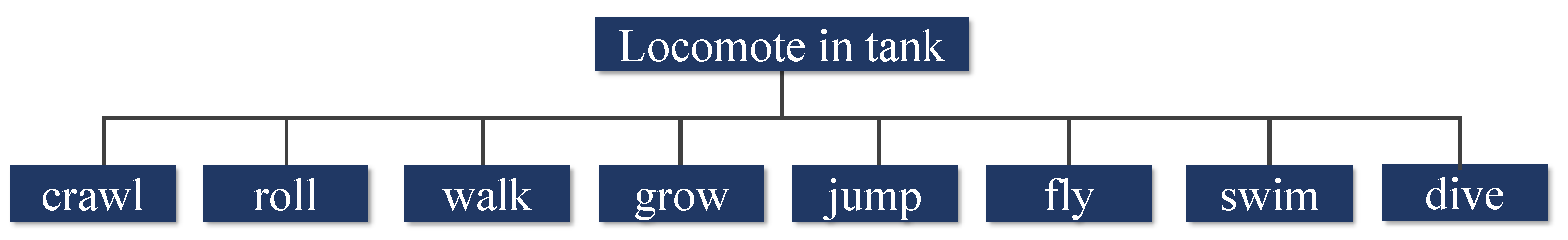
Figure 8 presents the abstract basic functions as well as the visualized results of the relevance and feasibility assessment. It can be seen that the function locomote in tank implied the highest relevance and least feasibility for tank inspection, due to the physical and process-related restrictions associated with the complex tank structure. Consequently, the problem statement was adjusted to locomote in tank.
3.3.2. Solution Space
In the light of the aforementioned basic functions for the tank inspection process, a morphological analysis was performed to generate different ideas as possible technical expressions. Therefore, an Ideating workshop using the creative techniques brain- and bodystorming was conducted. Hereby, the divergent thinking process was inspired by bionics and the literature review results (existing tank inspection systems) from the first iteration. The resulting alternatives represented abstract, basic approaches of how the respective function could technically be realized. For instance, the solution by Hawkes et al. [24] locomotes through growing or a jellyfish through diving. Besides that, some expressions (e.g., `crawl’) provided further levels of detail (e.g., `snake-like’ or `legged’).
Figure 9 illustrates the ideation results for the focused function `locomote in tank’. Moreover, this kind of morphological ideation was also performed for the other basic functions in Figure 8 to ensure consideration of possible cross-functional interdependencies between expressions. Thereupon in the phase Prototyping, the gathered ideas were sketched and constructed both virtually and/or physically using different tools, including `pen and paper’, whiteboards and CAD-based software. Accordingly, very first prototypes could be communicated to the executive level, other MRO researchers of the Institute of Maintenance, Repair and Overhaul and Lufthansa Technik for the purpose of feedback. Furthermore, these first prototypes enabled critical reviews regarding the process requirements such as the maximum size of a system or the minimal invasiveness. At this point, the phases Prototyping and Testing were performed highly iteratively with incrementally increasing level of detail, while the solution space was further narrowed down. For instance, `growing’ inspired by [24], turned out to be a critical alternative for fuel tank inspection, since explosion protection may be an issue due to an electromagnetic mechanism in the robot body.
With the iterative evaluation, discussion and improvement of the technical expressions, the aim was to derive a basis with different design options for the locomotion in the tank. Consequently, three basic concepts were derived.
3.3.3. Presentation and Discussion of Locomotion Variants
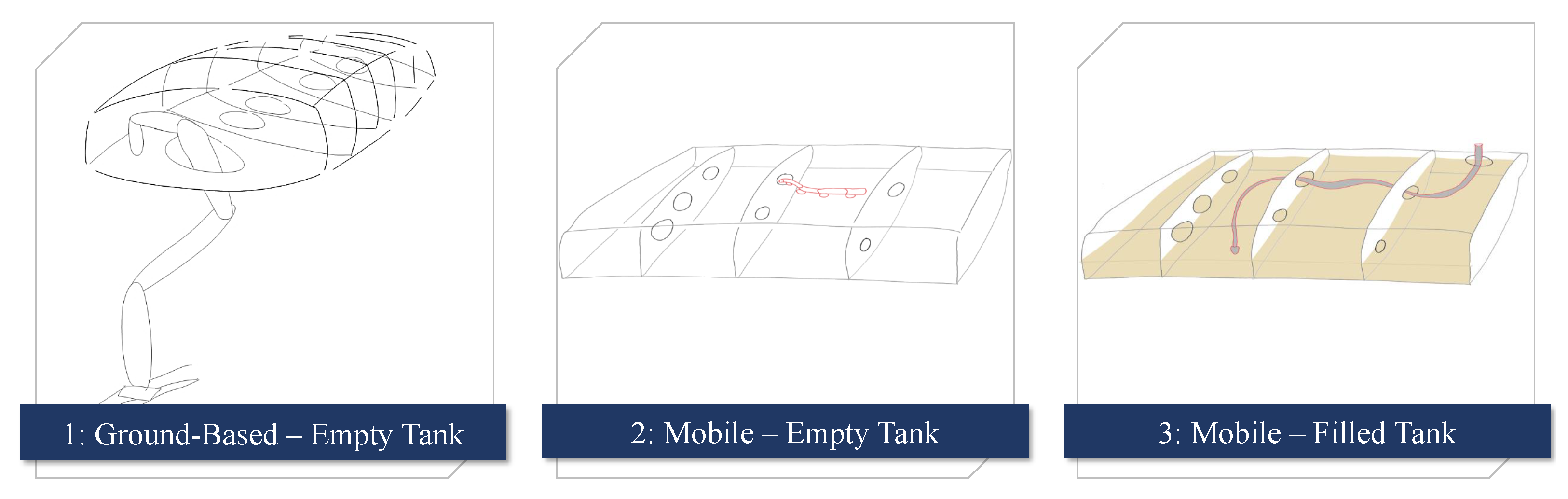
As a result of the design approach so far, this part presents and discusses three general approaches for a digital fuel tank inspection with focus on locomotion. The variants are displayed in Figure 10. Regarding the process requirements and problem dimensions given by the aircraft fuel tank environment, the most suitable and relevant variant is to be selected for further development.
The first sketch on the left represents the approach that is the closest adaption to the current process. Here, a (kinematically redundant) robotic arm will access the empty tank from the access panels. On the one hand, this will lead to reduced working time in the tank for the personnel, but on the other hand the time-consuming disadvantage of opening every access panel remains. Furthermore, tank structures are a highly complex environment to navigate through, which makes a very dexterous robotic arm necessary. Hyperreduntant robotic arms such as [19,32,33,34] could potentially execute those tasks. The second approach that was derived is a mobile system that can drive or crawl through an empty tank. The difference of only opening a specific entry port adds the benefit that most of the access panels could stay closed, what saves time. Nevertheless, this approach requires a highly sophisticated locomotion technique and relatively small dimensions to traverse the openings in the ribs between two tank chambers. Potential systems could be similar to [29,31,35,36,37]. The third option that was sketched is a submergible endoscopic system that could locomote respectively dive through a filled kerosene tank. Inspiring works are [28,38,39]. This approach yields many advantages such as saving time to drain the tank or opening access panels. Additionally, it could potentially be easier to handle in the context of robotic locomotion as such a system can float intrinsically. However, this approach would ask for a very strict explosion protection as kerosene is an explosive medium.
The solution design that offers the most advantages for the MRO staff and operational inspection process is represented by the third variant using a submergible endoscopic tool in a minimally invasive matter. Using a single point of entry avoids unnecessary opening of access panels, draining the tank and de-gassing the tank. An inherently explosion-proof system is inevitable. This requirement demands to design a novel endoscopic system, as none of the known systems are either inherently explosion-proof nor providing enough maneuverability to access all areas within the tank.
4. The Eeloscope Concept
Since the previous section defined an endoscopic system as the most desirable approach to enable a digital fuel tank inspection based on the underlying process needs, this section introduces the overall concept and development of the system called `Eeloscope’.
Figure 11 gives an impression of the intended concept by inserting an endoscopic probe into the wing tank minimally invasively and without having a human entering the tank. Based on the derived system requirements the maintenance personnel will operate the system using a control unit including a human machine interface. It is desirable to insert the system from any service access port in the wing structure and thus providing visual information from any given fuel tank area. In Figure 12, a generic representation of a wing fuel tank section is shown. As described in Section 2, wing fuel tanks are generally divided by ribs into multiple chambers. Figure 12 also shows how the Eeloscope traverses through the tank chambers by diving through the cutouts within the ribs.
An exemplary navigation approach is to enter from the outermost tank chamber and then moving inbound towards the fuselage. This approach yields the potential to fully cover the entire wing tank. As soon as the system has covered all intended areas, it can be pulled out. Therefore, it is important to first align the tip of the system to a straight line to prevent entangling. Since the system can be considered to be cabled, it also does not require any energy storage and wireless communication system, which usually are difficult to operate within kerosene tanks due to the larger size and bad propagation of electromagnetic signals within liquids, respectively. Being cable-bounded yields further advantages. One is the ability to evacuate the system quickly in the event of a control loss or emergency by pulling on the tail. Considering that a mobile robotic system is only capable of pushing through a flapper valve, the fuel tank could only be traversed in one direction. Using the cable-bounded system with a continuous diameter along the body shape keeps the flapper valve open, so that the endoscopic system can also be reversed towards the entry port. Additionally, foregoing a battery system saves the need for charging the system and saves weight, which yields better dynamic behavior. To handle the tail of the endoscopic system, a feeding mechanism at the entry point will be discussed in Section 4.2. Within the design process, the geometric specifications of the probe towards the commercially most common aircraft types, such as the Airbus A320 and Boeing 737 were considered.
In Figure 13, it can be seen that the endoscopic system can potentially fit through the holes within the ribs of a Boeing 737-700. This proves that based on the geometric design, the system could traverse multiple tank chambers for the given aircraft type. The core components of the system are the endoscopic probe, consisting of a head and a tail, the entry mechanism, the control unit and a human machine interface. The following subsections will provide a detailed look into the subcomponents of the Eeloscope.
4.1. Endoscopic Probe Design and Locomotion Technique
Based on the requirements from Section 2, an endoscopic robot was designed and prototypically constructed. Figure 13 shows the 3D-printed head, which contains an imaging sensor and the propulsion system. For the locomotion, the system has an active head that moves towards a desired direction. The tail of the system will only be actuated at the access mechanism using a feeding mechanism. The rest of the endoscopic body is passive. To ensure explosion protection, a novel actuation architecture is introduced for avoiding any electric actuators in the fuel tank. Therefore, the endoscope uses the kerosene itself as an energy transfer medium. The control unit can pump kerosene through the tail to the head of the endoscopic probe. Within the head, the kerosene will be guided to individual thruster nozzles on the outer hull. These thruster nozzles are responsible for a propulsion force that moves the whole system. This design uses the effects of Newton’s third law, which states that the action force equals the reaction force. Forces that are created from the nozzles will therefore move the endoscopic body. The nozzles are specifically arranged, so that it is possible to actuate six DoF at the tip of the endoscopic probe. To allow individual actuation of the degrees of freedom, the tail accommodates multiple small hoses, through which the kerosene can be pumped. Using this technique not only yields greater explosion protection compared to electric motors, it also heavily reduces the build volume of the endoscopic probe as it does not require any space for motors or batteries. This remote actuation is particularly beneficial, when the system moves within a confined space. A similar actuation method was used by Rico et al. in [38], Capara et al. in [39] and Ishii et al. in [40] since those systems are also using thruster nozzles to provide a locomotion force. Nevertheless, their architectures are using radial nozzle directions, which limits the rotational actuation. To overcome this limitation, a novel thruster nozzle and channel arrangement was created that guides the liquid towards the outlet in a tangential way.
In Figure 14, one can see the routing of the channels of the Eeloscope in detail. The system is symmetrical with respect to the -plane and the -plane. This allows for the capability to actuate six DoF. The two red channels from nozzles and and the two green channels from nozzles and have individual feeding hoses, since their nozzles are used by multiple basic motions. The blue channel for nozzles and and the yellow channel for nozzles and whereas are splitting into four individual channels. This is possible since these channels are always used in a combined motion. As the routing of the liquid flows is entirely passive and rigid, it offers great potential for miniaturization. Currently, the channel diameters are sized to 3 mm. Due to the space saving routing, a hollow chamber in the center of the cylinder is available for placing sensors and end effectors. The design also features hollow passages along the whole z-axis, which allows the routing of further mediums e.g., compressed air for pneumatic actuators and data cables.
The basic locomotion functions for translation and rotation are displayed in Figure 15. For every basic locomotion direction, which are the three translations along the x,y,z-axis and the three rotations about the x,y,z-axis, the system uses four thrusters. Those active thrusters are represented by green jets in Figure 15. Note that only the two fore jets are visible since the other two jets are mirrored behind the projected plane. For a forward translation along the z-axis, the system uses the four nozzles , , and . Moving backwards on the other hand requires the actuation of another set of thrusters, specifically , , and . Inverting the liquid flow by sucking would not yield to a precisely pointed force vector. This means, the system can only accelerate using an individual set of thrusters. For deceleration, the opposed set of thrusters must be used. To allow more stable motions, the Eeloscope always uses 4 thruster nozzles for one basic motion. In the case of combined motions, the individual motions are superposed.
In the case of a wing fuel tank inspection, it is important to provide a computer vision system that is capable of transmitting data over more than 15 m, since this is a typical wing length. Regarding the visual inspection, currently a commercial ethernet IP camera is integrated, namely the Lucid Vision Phoenix Camera with a Sony CMOS sensor. The camera was fitted with a wide-angle lens that offers a field of view of . In the context of removing all electric components, this camera system is only used during operation in water in the development stage, as it is not fully explosion-proof. In Section 6, this topic and the missing light source with respect to future work of this project is addressed.
Using this technique now allows for an actuated endoscopic inspection of a filled aircraft tank. Using the kerosene as a locomotion mean contributes to fulfilling the explosion protection requirement in a more intrinsic way compared to classical wheeled and legged mobile robotic systems with electric motors.
4.2. Wing Tank Access
A further challenge for an endoscopic system is the entry into the inspection area. Generally, aircraft fuel tanks do not have dedicated entry ports for endoscopic systems. Therefore, its necessary to use existing wing access panels to enter the tank. For commercial aircraft typical access possibilities are the fueling nozzles, fuel dumping valves and maintenance access panels. Within this project, the maintenance access panels on the lower side of the wing as seen in Figure 11 were used, since those are offering the possibility for a feeding mechanism. The feeding mechanism also serves as strain relief for the endoscopic head. Using access panels for the entry allows for an application on a wide range of aircraft and offers the possibility to directly access desired tank areas, since almost every tank chamber has its own access panel. The development of the wing tank access mechanism is subject to future work.
4.3. Pump Unit
To power the endoscope nozzles, a pump unit was constructed as shown in Figure 16. The pump unit holds ten pumps for the individual inlets of Eeloscope with 6DoF. The fuel supply for the endoscope propulsion could either be generated from a reservoir or from a direct connection to the wing tank. This system is incorporating a reservoir to also maintain a constant fuel level, which is beneficial for controlling the kerosene flow. The pump unit also holds the main flow control loops, each consisting of a brushless DC-Motor connected to a pump and a flow sensor. Those motors are controlled using the flow sensors on the top, to regulate the flow within the individual hoses. This will allow a more accurate control of the liquid flows. The pump unit is designed to be portable for flexible use on different platforms, e.g., as shown in Figure 11.
4.4. Human Machine Interface
The human machine interface (HMI) has a key role in enabling a more human-friendly tank inspection process. It helps to overcome many of the previously mentioned hardships of the maintenance personnel by providing a comfortable working environment. To allow a more distributed inspection, the HMI could potentially be placed anywhere, as long as it is possible to establish a data connection to the Eeloscope system. It hereby also enables the possibility for remote inspections for example by the aircraft manufacturer to allow expert consulting. To operate the system, the HMI is designed to allow control of the Eeloscope and inspection at the same time. As the HMI is the main source of information for the maintenance personnel, all the relevant information, such as task descriptions, documentations and findings, need to be displayed.
As shown in Figure 17, the live video stream is placed centrally on the display. On the left side, all information regarding the Eeloscope’s position inside the tank and relevant parameters, such as the inserted length, is displayed. The small map on the lower left side is indicating the roll orientation and global position within the wing tank. On the right side, information regarding the inspection process is displayed by providing a checklist that is derived from the AMM. In the case of a defect detection, one can add the finding to a list. This HMI is still subject to further research, specifically possible user input devices such as keyboards or joysticks will be considered.
5. Experimental Evaluation
This section will show first experiments to illustrate the proof of concept of the Eeloscope technology. Since this endoscopic inspection approach is entirely novel, the initial experiments are separated into different areas concerning the overall process. The initial focus is set on the Eeloscope related experiments.
5.1. Experimental Environment
To design and improve the robotic endoscope, it was decided to use substitute models for the individual disciplines locomotion and inspection. In Figure 18, two different setups are shown. On the left-hand side, a water basin is used to test the fundamental locomotion capabilities inside a liquid. This environment is used to reduce the complexity at the beginning of the development process. For experiments that evaluate the visual inspection and camera localization capabilities, a wing section cut from a scrapped Boeing 737-700 is used. To avoid the complex handling of explosive kerosene fuel during the experimental research process, water was used as a substitute liquid. This is possible since kerosene has a similar viscosity compared to water and is transparent.
5.2. Basic Motion Experiments
As the prototypes of the Eeloscope are developed iteratively, the experiments began with basic locomotion experiments with a 4DoF robot. This system can translate along all axes and rotate about its z-axis. In this experiment, the system was manually steered in an open loop using a joypad controller. Apart from an inertial measurement unit (IMU), the system had no sensor for absolute pose estimation. Therefore, position feedback was gained by a top view into the basin. As shown in Figure 19, it was possible to repetitively traverse a hole with a 6 cm diameter inside a vertical plane, which was placed in the water basin. This test showed that the basic locomotion technique is sufficiently precise to traverse holes within a structure that is similar to the interior of an aircraft wing fuel tank. Nevertheless, this only proves the possible steering precision using manual control. So far, this does not prove that the Eeloscope is able to traverse entire fuel tank structures. This must be demonstrated in further investigations. This experiment only used a kinematic mapping between cartesian input velocities towards pump voltages for the individual nozzles. It was noticed that the system takes a lot of concentration from the user to eliminate disturbances in the motion. This is not desirable, since this project aims to relieve the maintenance personnel from external tasks to allow for complete concentration on the inspection process.
5.3. Camera-Based Position Control
To allow easier steering of the Eeloscope, a position control was developed to automatically hold the current position, while the user has the possibility to command a desired target position. Since an external position feedback, such as in Section 5.2, is not feasible inside a closed tank, it was decided to use the built-in camera for autonomous pose estimation. It is desirable to make use of a visual simultaneous localization and mapping (SLAM) algorithm to explore the tank interior and localize the Eeloscope within that environment. As the water basin does not feature enough optical landmarks to provide a stable monocular visual SLAM pose estimation, AR-markers were used for pose estimation. To compute the pose estimation relatively to the marker, the ARUCO package from Garrido-Jurado et al. [41] was used in combination with the Robot Operating System (ROS) [42]. Because those markers are clearly not existing in actual aircraft wings, the use of monocular visual SLAM inside the Boeing 737-700 tank section is demonstrated in Section 5.4. Figure 20 illustrates the setup for trials towards a camera-based position control. To reduce the refraction influences of the liquid, the camera was calibrated underwater using a checkerboard. In the first trial, the aim was to hold a specified position on the water surface to proof the controllability. The Eeloscope was placed in front of the AR-marker, so that the camera could see the marker, as shown in the lower right image. As long as the control algorithm was not activated, the Eeloscope drifted towards the left side due to internal stresses and pretension of the hoses. This implies that in some configurations, the system is not intrinsically stable. In the initial tests, a negative feedback P-Controller was used that computes the error relatively to the target position and incorporates that value for the thruster commands. The target position was set to x = 0.0 m and z = 0.36 m, while the y-axis was not controlled in this case. As soon as the z & x axis of the robot were controlled, the system maintained the position within a specific range.
The resulting deviations of the position control can be seen in the graphs of Figure 21. In the left graph, the position in the x and z direction is plotted. The measurement was recorded over a duration of 25 s using the intrinsic camera with the ARUCO pose estimation package. In this time period, the system was trying to reach the target position. Since only a basic proportional controller was used, the system tends to overshoot.
The oscillating behavior is shown in detail in the two right graphs of Figure 21 by plotting the individual axes x and z over the time t. The system oscillates with different frequencies, which leads to the trajectory of the left graph in the x-z-plane. The error range for the x-axis is within 7.5 cm compared to 2.0 cm for the z-axis. This difference can be explained by the disturbance force that is induced to the tip by the hoses. This experiment has not integrated a flow-controlled pump system. These results show that the development of control algorithms need further investigations.
The subject matter of future research will specifically address improvements regarding the overall control architecture with the aim to optimize position control stability. Nevertheless, the results show great potential for this novel locomotion approach to be fitted with suitable control algorithms to provide a stable motion control.
5.4. Monocular Visual SLAM within an Aircraft Wing Tank
As described in the previous subsection, it is preferable to provide a camera vision-based pose estimation to maintain a stable position within the tank. In addition to that, it is also desirable to estimate the global location of the system within the whole fuel tank. For this problem, SLAM algorithms are of special interest. As SLAM algorithms are available in open-source packages, the orb-slam package from Mur-Artal [43] was applied to the input image of an empty and externally illuminated fuel tank section of the Boeing 737-700 wing demonstrator. The main goal here was to ensure that a generic monocular visual SLAM algorithm can extract enough image feature for computing a pose estimation. The result can be seen in Figure 22. The lower left image is the input image. On the upper left image, one can see the gray-scaled input image with the green feature landmarks that are tracked within the image sequences. The computed pose estimation is represented by the red arrow in the right map. In the future, the geometric accuracy and the capabilities for localization over multiple tank chambers must be evaluated. Here, it is especially interesting to evaluate the capabilities regarding the optical similarity of all tank chambers.
6. Discussion and Outlook
This section provides a critical discussion of the proposed solution and is structured by the problem dimensions and process requirements mentioned in Section 2. As the developed prototype is at an early stage using substitute environments such as a water basin, there is a huge potential of increasing the degree of fulfilment regarding several requirements. Accordingly, an outlook on further potentials in aircraft fuel tank maintenance is given.
6.1. Critical Review Regarding Problem Dimensions
The major demanded goal for the design of a maintenance assisted system was to relieve the mechanics. With the proposed solution, they no longer must enter the tanks for inspections. Nevertheless, the current approach does not include end effectors for repair tasks. In the case of a finding, this approach still requires the staff to physically enter the tank. Consequently, future research should address physical interactions such as cleaning functionalities for the tank to prophylactically eliminate causes of corrosion. Further investigation should also be conducted regarding the usability of the Eeloscope to ensure actual stress relieve. A hardly usable and controllable system could still distract mechanics during the inspection.
As another goal was to reduce the overhead to make the process more efficient, this approach does not need every access panel to be opened to retrieve visual inspection data. Consequently, the required MRO personnel can be reduced. However, the tank accessibility still poses a challenge, since fuel tanks do not provide minimally invasive inspection ports. Hence, further research needs to be conducted to minimize the efforts for inserting the Eeloscope into the tank. This aspect is also influenced by the fuel level of the tank. Depending on whether the tank is filled or empty, the entry process will vary.
Since the third problem dimension was the lack of digital transparency, the presented approach enables the streaming of a colored video from inside the tank for inspection purposes. However, a comprehensive experimental evaluation concerning the ability of inspection is still subject to ongoing research. In particular, the video quality inside a dark tank with a built-in light source must be examined in future experiments. This must ensure that all types of defects can be inspected using the generated digital inspection data even while being submerged in kerosene. Furthermore, the interface to Digital Twins and the corresponding digital availability for the application of prescriptive maintenance and condition-monitoring strategies must be further examined.
6.2. Critical Review Regarding System Requirements
The explosion protection represented the most important requirement with respect to the development of an assisting system for fuel tank inspection. Therefore, an inherently passive endoscope was introduced. As the system body does not contain any electric actuators within the fuel tank, the efforts regarding explosion protection can concentrate on the pump unit. Designing explosion-proof pump units can be considered to be feasible, since those systems are widely used in the context of fueling and defueling aircraft. At the moment, the Eeloscope does not include any light source but uses an ethernet camera, which makes the system currently not explosion protected. In the future, it is desirable to exchange the camera with an optical fiber-based camera system that has the image sensor outside of the tank. Furthermore, the light source could also use optical fibers to guide light beams into the tank from outside. Consequently, a system without any electric components would result and thereby would make the certification process for explosion protection much easier compared to the existing systems. Nevertheless, this step should not conflict with the data quality that is used for the anomaly detection.
Another system requirement was the failure safety that was fulfilled using a cabled endoscopic system. In the case of an unexpected event, such as a loss of power or connection issues to the Eeloscope, this approach claims to have the possibility to be pulled out by hand. However, this still needs to be proved in an actual aircraft fuel tank as only a water basin was used during the development.
The last two requirements are specifically addressing the capabilities of the robotic system. As of the authors knowledge, the wing tank is passable through holes with a diameter of not more than 6 cm. However, it still must be tested especially in the outer wing tank area with respect to minimal curvature radii. Here, the Eeloscope might still be too large with a length of 120 mm of the rigid endoscope tip. Under these circumstances, the system would need to be miniaturized even more. This would also affect the maneuverability, which is the last system requirement. Here, dedicated experiments must proof whether the Eeloscope can actually locomote through any tank area. A big challenge is still seen by traversing longer distances within the tank as this requires relatively high propulsion forces to overcome the friction. In this case, a buoyancy control mechanism could be beneficial to always float in the tank and prevent sinking to the tank floor. Additionally, different materials for the Eeloscope body should be investigated to allow higher maneuverability. This can also be influenced by more sophisticated robot control algorithms.
6.3. Outlook—Eeloscope as a Decision Support System
The design and development of the Eeloscope could enable entirely new processes for fuel tank maintenance. One of the greatest process-related advantages is the possibility to decouple the inspection process from the heavy check. As an example, the inspection with the Eeloscope could be executed within a scheduled line maintenance before a heavy check. This contributes towards an early-stage decision support, in particular to plan which tank areas need MRO actions such as repairs or decontamination. Consequently, only the necessary tank sections must be opened during the heavy check. Another benefit is that no safety supervisor is needed to monitor the mechanic inside the tank with the proposed endoscopic inspection. The novel approach also yields the benefit that the tank will only be opened for a shorter time. Note that as of the AMM, no electricity is allowed to be active on the entire aircraft, whenever the tank is open. This prevents the execution of other functional tests in parallel within the heavy check. Thus, minimizing the time where the tank is opened is desirable to not restrict other maintenance actions that are not connected to the fuel tank maintenance. Using the Eeloscope before a heavy check also supports the planning of repair infrastructure and resources (staff and tools) as well as required logistics (e.g., spare parts) in advance. Hereby, this reduces the risks of unscheduled maintenance actions or delays in the maintenance program planning as the necessary repair tasks are known before the aircraft is arriving at the hangar for a heavy check.
The generation of digital inspection data offers great potential when feeding the data to Digital Twins and thereby making the data available for prognostics and health monitoring (PHM) methods. Furthermore, remote inspections could be executed. This means that a mechanic could act as an Eeloscope operator with the task to scan all areas of interest. Nevertheless, it would not require the expertise of classifying and analyzing the data as this could potentially be done in a remote position from an expert. Therefore, innovative technologies such as virtual or augmented reality can support such novel remote maintenance processes.
This work also contributes towards a potential aircraft fuel tank redesign. With the proposed system in mind, future aircraft could integrate inspection ports to fuel tanks, since they are already a standard in the context of minimally invasive jet turbine inspections. Allowing robots to enter the tank by an inherently robot friendly design, it is plausible to consider that all or many of the access panels may be eliminated. This could result in a more lightweight design of aircraft wings, as the existing access panel structures are imposing more weight to the wing.
7. Conclusions
This research article presented initial steps towards a novel endoscopic system that is specifically tailored to the needs of aircraft wing fuel tank inspection. Through the application of a Design Thinking methodology, various problem dimensions were identified. Accordingly, a process analysis showed that mechanics and planning staff are suffering from harsh working conditions associated with intensive preparations and the lack of digital tank condition transparency. A review of the current state of R&D revealed that the robotic inspection systems found did not sufficiently meet the process requirements. By the application of creative methods in ideation loops, several solution designs were achieved and discussed. The proposed system Eeloscope will be able to access the fuel tank in a minimally invasive matter and thereby not only relieve the mechanics from the arduous work, but is also able to provide inspection data a priori to a heavy check. This allows the selective opening of fuel tank chambers for dedicated repair actions as well as shorter tank opening times. Using a minimally invasive approach yields safety advantages for mechanics and aircraft at the same time and increases the digital inspection data availability and transparency. Overall, the Eeloscope allows an entire change to the fuel tank maintenance process.
8. Patents
A patent application is currently ongoing as of March 2021.
Author Contributions
Conceptualization, F.H. and A.D.; methodology, A.D.; software, F.H.; validation, F.H.; formal analysis, F.H. and A.D.; investigation, F.H. and A.D.; resources, K.W.; data curation, F.H.; writing—original draft preparation, F.H. and A.D.; writing—review and editing, K.W.; visualization, F.H. and A.D.; supervision, K.W.; project administration, F.H. and A.D.; funding acquisition, K.W. All authors have read and agreed to the published version of the manuscript.
Funding
This research received no external funding.
Institutional Review Board Statement
Not applicable.
Informed Consent Statement
Not applicable.
Acknowledgments
We kindly thank our colleagues for the fruitful discussions. In particular, we want to thank Rebecca Rodeck, Hendrik Meyer, Ivan Belyaev and Mostafa Selim. Furthermore, we would like to thank Lufthansa Technik for consulting regarding maintenance related details. This work resulted from an initiative of the Innovation Management and the corresponding internal project `FuTaMa’ at the DLR Institute of Maintenance, Repair and Overhaul.
Conflicts of Interest
The authors declare no conflict of interest. The funders had no role in the design of the study; in the collection, analyses, or interpretation of data; in the writing of the manuscript, or in the decision to publish the results.
Abbreviations
The following abbreviations are used in this manuscript:
| MRO | Maintenance, repair and overhaul |
| FAA | Federal Aviation Administration |
| EASA | European Union Aviation Safety Agency |
| MPD | Maintenance planning document |
| AMM | Aircraft maintenance manual |
| GVI | General visual inspection |
| VCK | Visual check |
| EWIS | Electrical wiring interconnection system |
| DT | Design Thinking |
| R&D | Research and Development |
| DoF | Degrees of freedom |
| SLAM | Simultaneous localization and mapping |
References
- National Transportation Safety Board Aircraft Accident Report TWA 800. Available online: https://lessonslearned.faa.gov/TWA800/TWA800NTSBreport.pdf (accessed on 29 March 2021).
- Aircraft Accident Report Thai Airways Flight 114. Available online: https://www.fss.aero/accident-reports/dvdfiles/TH/2001-03-03-TH.pdf (accessed on 29 March 2021).
- Certification Specifications for Large Aeroplanes CS-25. Available online: https://www.easa.europa.eu/sites/default/files/dfu/CS-25%20Amdt%207%20%28combined%29%20%28%2B%20header%29.pdf (accessed on 29 March 2021).
- Hill, E.C.; Hill, G.C. Microbial Contamination and Associated Corrosion in Fuels, during Storage, Distribution and Use. AMR 2008, 38, 257–268. [Google Scholar] [CrossRef]
- FAA AC. Available online: https://www.faa.gov/documentLibrary/media/Advisory_Circular/AC%20120-98A.pdf (accessed on 29 March 2021).
- Airbus A320 Maintenance Planning Document (MPD). Available online: https://de.scribd.com/document/394485679/mpd-a320-pdf (accessed on 29 March 2021).
- Carlton, G.N.; Smith, L.B. Exposures to jet fuel and benzene during aircraft fuel tank repair in the U.S. Air Force. Appl. Occup. Environ. Hyg. 2000, 15, 485–491. [Google Scholar] [CrossRef] [PubMed]
- Pleil, J.D.; Smith, L.B.; Zelnick, S.D. Personal exposure to JP-8 jet fuel vapors and exhaust at air force bases. Environ. Health Perspect. 2000, 108, 183–192. [Google Scholar] [CrossRef] [PubMed]
- Ritchie, G.; Still, K.; Rossi, J.; Bekkedal, M.; Bobb, A.; Arfsten, D. Biological and health effects of exposure to kerosene-based jet fuels and performance additives. J. Toxicol. Environ. Health B Crit. Rev. 2003, 6, 357–451. [Google Scholar] [CrossRef] [PubMed]
- D’Este, C.; Attia, J.R.; Brown, A.M.; Gibson, R.; Gibberd, R.; Tavener, M.; Guest, M.; Horsley, K.; Harrex, W.; Ross, J. Cancer incidence and mortality in aircraft maintenance workers. Am. J. Ind. Med. 2008, 51, 16–23. [Google Scholar] [CrossRef] [PubMed]
- Airbus Skywise Platform. Available online: https://skywise.airbus.com/ (accessed on 28 April 2021).
- Lufthansa Technik Aviatar. Available online: https://www.lufthansa-technik.com/de/aviatar (accessed on 28 April 2021).
- General Electric Digital Predix Platform. Available online: https://www.ge.com/digital/iiot-platform (accessed on 28 April 2021).
- Meinel, C.; Leifer, L. Design Thinking Research. In Design Thinking: Understand—Improve—Apply; Plattner, H., Meinel, C., Leifer, L., Eds.; Springer: Berlin/Heidelberg, Germany, 2011; pp. xiii–xxi. ISBN 978-3-642-13756-3. [Google Scholar]
- Hasso Plattner Institute for Digital Engineering gGmbH. The Six Phases of the Design Thinking Process. Available online: https://hpi.de/en/school-of-design-thinking/design-thinking/background/design-thinking-process.html (accessed on 24 March 2021).
- Plattner, H.; Meinel, C.; Weinberg, U. Design Thinking: Innovation Lernen; Ideenwelten Offnen; mi-FinanzBuch Verl.: München, Germany, 2009; ISBN 978-3868800135. [Google Scholar]
- Lindberg, T.; Meinel, C.; Wagner, R. Design Thinking: A Fruitful Concept for IT Development? In Design Thinking: Understand—Improve—Apply; Plattner, H., Meinel, C., Leifer, L., Eds.; Springer: Berlin/Heidelberg, Germany, 2011; pp. 3–18. ISBN 978-3-642-13756-3. [Google Scholar]
- Lawson, B. How Designers Think: The Design Process Demystified, 4th ed.; ElsevierArchitectural Press: Amsterdam, The Netherlands, 2006; ISBN 9780750660778. [Google Scholar]
- Anscombe, R.; Bryant, A.; Buckingham, R.; Ferguson, G.; Graham, A.; Lichon, M.; Parry, N.; Brandrick, P.; Redman, M.; Summers, M.; et al. Snake-Arm Robots: A New Approach to Aircraft Assembly. In Proceedings of the Aerospace Manufacturing and Automated Fastening Conference and Exhibition, Toulouse, France, 11–14 September 2006; SAE International: Warrendale, PA, USA, 2006. [Google Scholar] [CrossRef]
- Gao, Q.J.; Wang, W.J.; Niu, G.C. Design Bionic Structure and Analysis of Kinematics for Aircraft Fuel Tank Inspection Robot. AMM 2013, 278–280, 594–598. [Google Scholar] [CrossRef]
- Alatorre, D.; Nasser, B.; Rabani, A.; Nagy-Sochacki, A.; Dong, X.; Axinte, D.; Kell, J. Teleoperated, In Situ Repair of an Aeroengine: Overcoming the Internet Latency Hurdle. IEEE Robot. Automat. Mag. 2019, 26, 10–20. [Google Scholar] [CrossRef]
- Wang, M.; Palmer, D.; Dong, X.; Alatorre, D.; Axinte, D.; Norton, A. Design and Development of a Slender Dual-Structure Continuum Robot for In-Situ Aeroengine Repair. In Proceedings of the Towards a Robotic Society, 2018 IEEE/RSJ International Conference on Intelligent Robots and Systems, Madrid, Spain, 1–5 October 2018; IEEE: Piscataway, NJ, USA, 2018; pp. 5648–5653, ISBN 978-1-5386-8094-0. [Google Scholar]
- Brusell, A.; Andrikopoulos, G.; Nikolakopoulos, G. Vortex Robot Platform for Autonomous Inspection: Modeling and Simulation. In Proceedings of the 45th Annual Conference of the IEEE Industrial Electronics Society (IECON 2019), Lisbon, Portugal, 14–17 October 2019; IEEE: Piscataway, NJ, USA, 2019; pp. 756–762, ISBN 978-1-7281-4878-6. [Google Scholar]
- Hawkes, E.W.; Blumenschein, L.H.; Greer, J.D.; Okamura, A.M. A soft robot that navigates its environment through growth. Sci. Robot. 2017, 2. [Google Scholar] [CrossRef] [PubMed] [Green Version]
- Festo. Available online: https://www.festo.com/PDF_Flip/corp/Festo_BionicFinWave/en/ (accessed on 28 March 2021).
- Christensen, L.; Fischer, N.; Kroffke, S.; Lemburg, J.; Ahlers, R. Cost-Effective Autonomous Robots for Ballast Water Tank Inspection. J. Ship Product. Des. 2011, 27, 127–136. [Google Scholar]
- Waygate Technologies. Available online: https://inspection-robotics.com/bike/ (accessed on 28 March 2021).
- Kelasidi, E.; Liljeback, P.; Pettersen, K.Y.; Gravdahl, J.T. Innovation in Underwater Robots: Biologically Inspired Swimming Snake Robots. IEEE Robot. Automat. Mag. 2016, 23, 44–62. [Google Scholar] [CrossRef] [Green Version]
- Sarcos Robotics. Available online: https://www.sarcos.com/products/guardian-s/ (accessed on 28 March 2021).
- Eich, M.; Vogele, T. Design and control of a lightweight magnetic climbing robot for vessel inspection. In Proceedings of the 19th Mediterranean Conference on Control & Automation (MED), Corfu, Greece, 20–23 June 2011; IEEE: Piscataway, NJ, USA, 2011; pp. 1200–1205, ISBN 978-1-4577-0124-5. [Google Scholar]
- Gorner, M.; Wimbock, T.; Baumann, A.; Fuchs, M.; Bahls, T.; Grebenstein, M.; Borst, C.; Butterfass, J.; Hirzinger, G. The DLR-Crawler: A testbed for actively compliant hexapod walking based on the fingers of DLR-Hand II. In Proceedings of the 2008 IEEE/RSJ International Conference on Intelligent Robots and Systems (IROS 2008), Nice, France, 22–26 September 2008; IEEE Service Center: Piscataway, NJ, USA, 2008; pp. 1525–1531, ISBN 978-1-4244-2057-5. [Google Scholar]
- Mehling, J.S.; Diftler, M.A.; Chu, M.; Valvo, M. A Minimally Invasive Tendril Robot for In-Space Inspection. In Proceedings of the IEEE/RAS-EMBS International Conference on Biomedical Robotics and Biomechatronics, Pisa, Italy, 20–22 February 2006; IEEE: Piscataway, NJ, USA, 2006; pp. 690–695, ISBN 1-4244-0040-6. [Google Scholar]
- Takeichi, M.; Suzumori, K.; Endo, G.; Nabae, H. Development of a 20-m-long Giacometti arm with balloon body based on kinematic model with air resistance. In Proceedings of the IEEE/RSJ International Conference on Intelligent Robots and Systems (IROS), Vancouver, BC, Canada, 24–28 September 2018; IEEE: Piscataway, NJ, USA, 2017; pp. 2710–2716, ISBN 978-1-5386-2682-5. [Google Scholar]
- HiBot. Available online: https://www.hibot.co.jp/products/floatarm/ (accessed on 28 March 2021).
- Hirose, S.; Mori, M. Biologically Inspired Snake-like Robots. In In Proceedings of the 2004 IEEE International Conference on Robotics and Biomimetics, Shenyang, China, 22–26 August 2004; IEEE: Piscataway, NJ, USA, 2004; pp. 1–7, ISBN 0-7803-8614-8. [Google Scholar]
- Debenest, P.; Guarnieri, M.; Hirose, S. PipeTron series—Robots for pipe inspection. In Proceedings of the 2014 3rd International Conference on Applied Robotics for the Power Industry (CARPI), Foz do Iguassu, Brazil, 14–16 October 2014; IEEE: Piscataway, NJ, USA, 2014; pp. 1–6, ISBN 978-1-4799-6422-2. [Google Scholar]
- Wright, C.; Buchan, A.; Brown, B.; Geist, J.; Schwerin, M.; Rollinson, D.; Tesch, M.; Choset, H. Design and architecture of the unified modular snake robot. In Proceedings of the IEEE International Conference on Robotics and Automation (ICRA), Saint Paul, MN, USA, 14–18 May 2012; IEEE: Piscataway, NJ, USA, 2012; pp. 4347–4354, ISBN 978-1-4673-1405-3. [Google Scholar]
- Rico, J.A.S.; Endo, G.; Hirose, S.; Yamada, H. Development of an actuation system based on water jet propulsion for a slim long-reach robot. Robomech. J. 2017, 4, 1–17. [Google Scholar] [CrossRef]
- Caprara, R.; Obstein, K.L.; Scozzarro, G.; Di Natali, C.; Beccani, M.; Morgan, D.R.; Valdastri, P. A platform for gastric cancer screening in low- and middle-income countries. IEEE Trans. Biomed. Eng. 2015, 62, 1324–1332. [Google Scholar] [CrossRef] [PubMed] [Green Version]
- Ishii, A.; Ambe, Y.; Yamauchi, Y.; Ando, H.; Konyo, M.; Tadakuma, K.; Tadokoro, S. Design and Development of Biaxial Active Nozzle with Flexible Flow Channel for Air Floating Active Scope Camera. In Proceedings of the Towards a Robotic Society, 2018 IEEE/RSJ International Conference on Intelligent Robots and Systems, Madrid, Spain, 1–5 October 2018; IEEE: Piscataway, NJ, USA, 2018; pp. 442–449, ISBN 978-1-5386-8094-0. [Google Scholar]
- Garrido-Jurado, S.; Muñoz-Salinas, R.; Madrid-Cuevas, F.J.; Marín-Jiménez, M.J. Automatic generation and detection of highly reliable fiducial markers under occlusion. Pattern Recognit. 2014, 47, 2280–2292. [Google Scholar] [CrossRef]
- Quigley, M.; Gerkey, B.; Conley, K.; Faust, J.; Foote, T.; Leibs, J.; Berger, E.; Wheeler, R.; Ng, A.Y. ROS: An open-source Robot Operating System. In Proceedings of the Open-Source Software workshop of the International Conference on Robotics and Automation (ICRA), Kobe, Japan, 12–17 May 2009. [Google Scholar]
- Mur-Artal, R.; Montiel, J.M.M.; Tardos, J.D. ORB-SLAM: A Versatile and Accurate Monocular SLAM System. IEEE Trans. Robot. 2015, 31, 1147–1163. [Google Scholar] [CrossRef] [Green Version]
Figure 1.
The fuel tank chambers of an aircraft are mainly situated in the wings, but also within the center of the fuselage.
Figure 1.
The fuel tank chambers of an aircraft are mainly situated in the wings, but also within the center of the fuselage.

Figure 2.
The wing fuel tank chambers of an Airbus A320 at ribs four and twelve from inside. The dimensions indicate the size of the individual tank chambers, where the mechanics must climb into. These images were created in a training and research tank demonstrator at Lufthansa Technik in Hamburg, Germany.

Figure 3.
Fuel Tank Maintenance Process Chain.

Figure 4.
Derived Problem Dimensions in Fuel Tank Maintenance.

Figure 5.
Overview of Problem Dimensions and System Requirements.


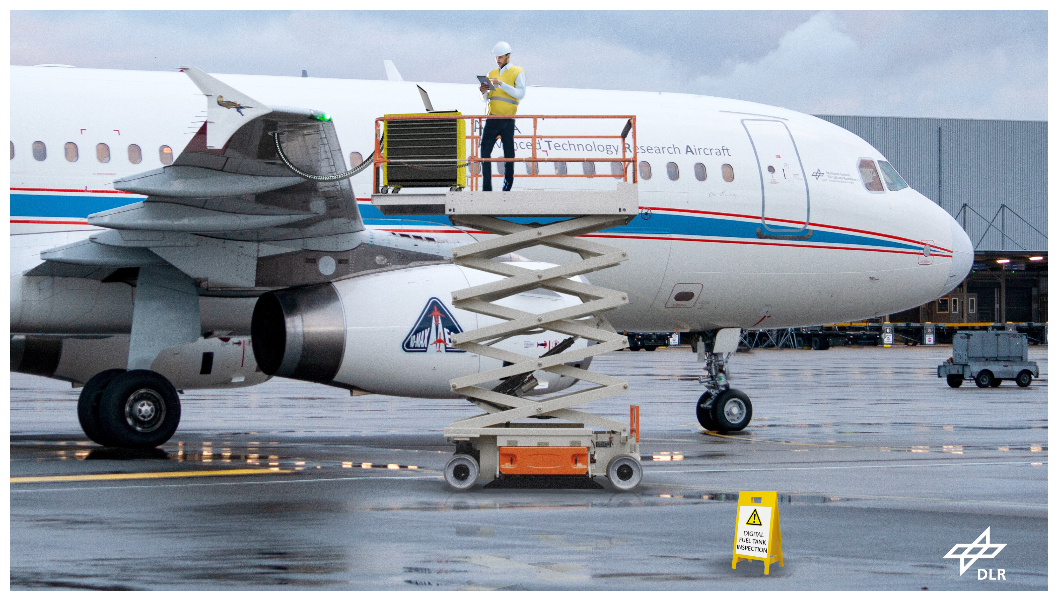
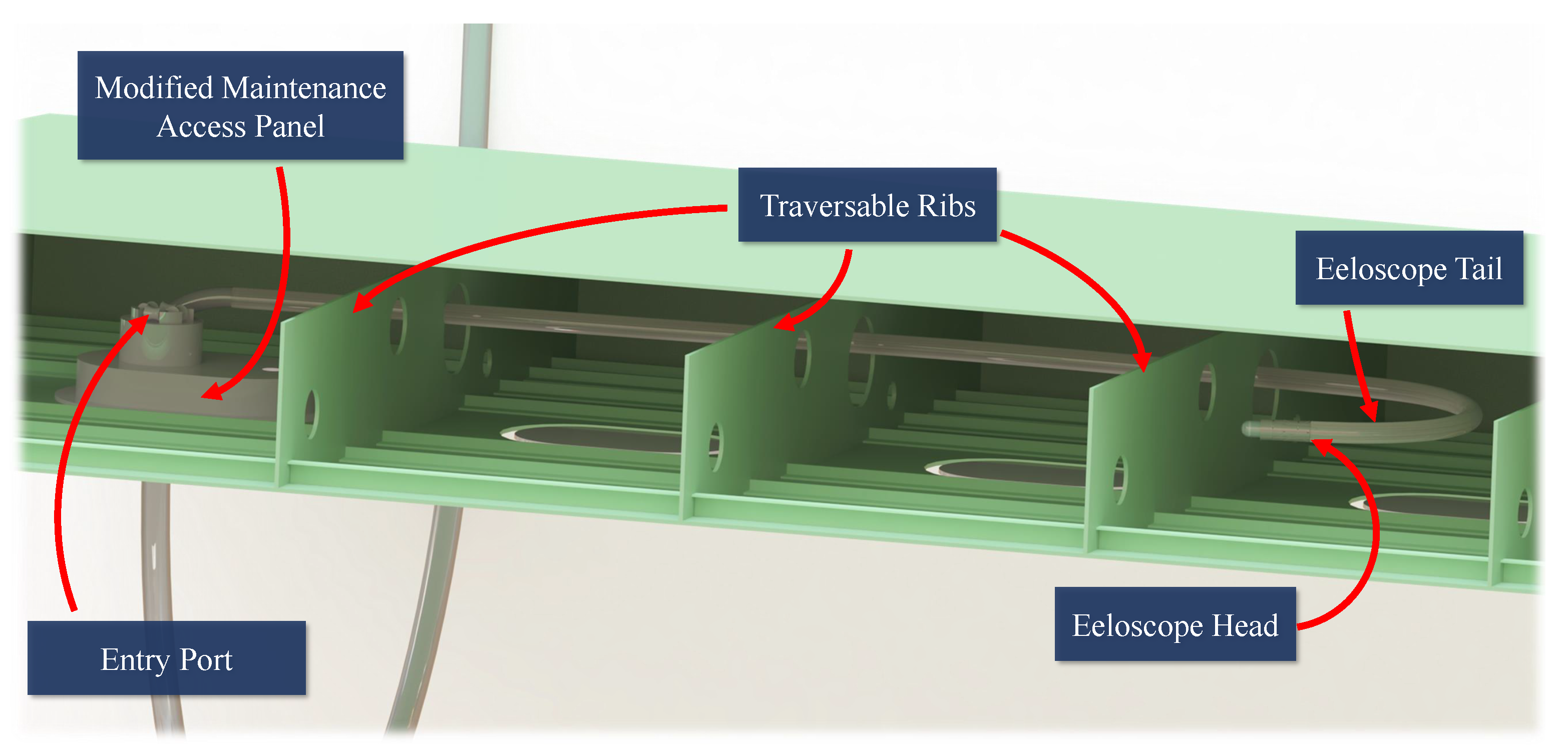
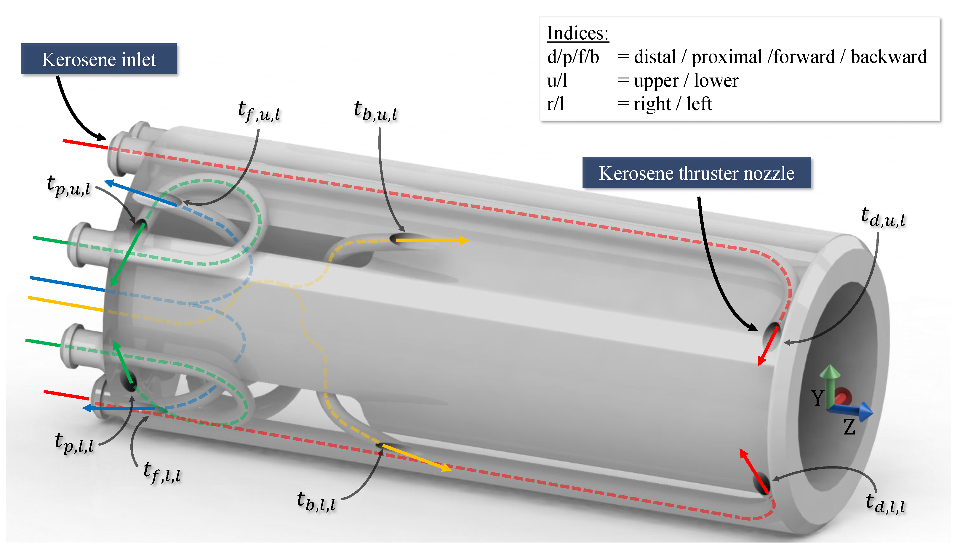
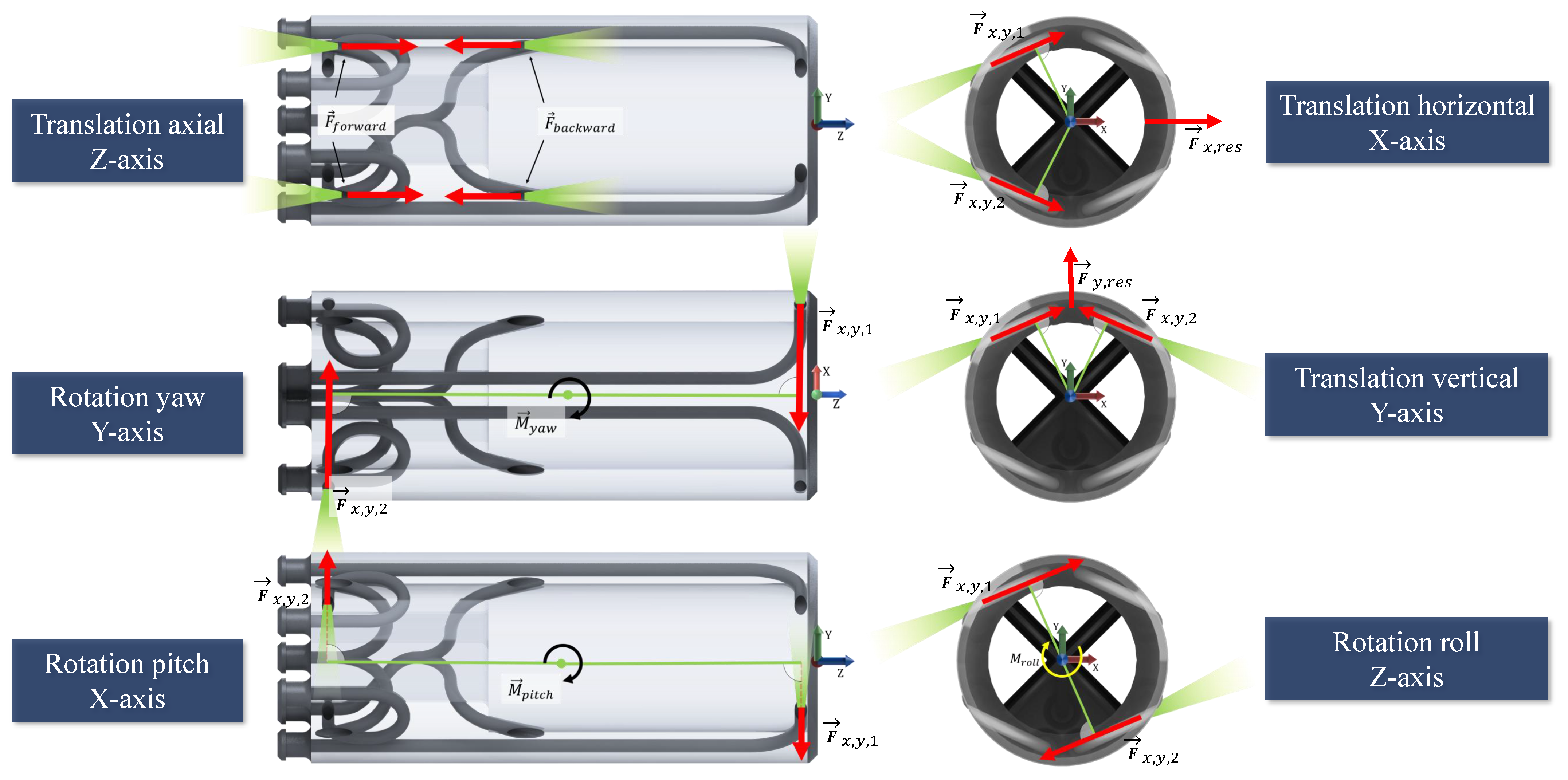
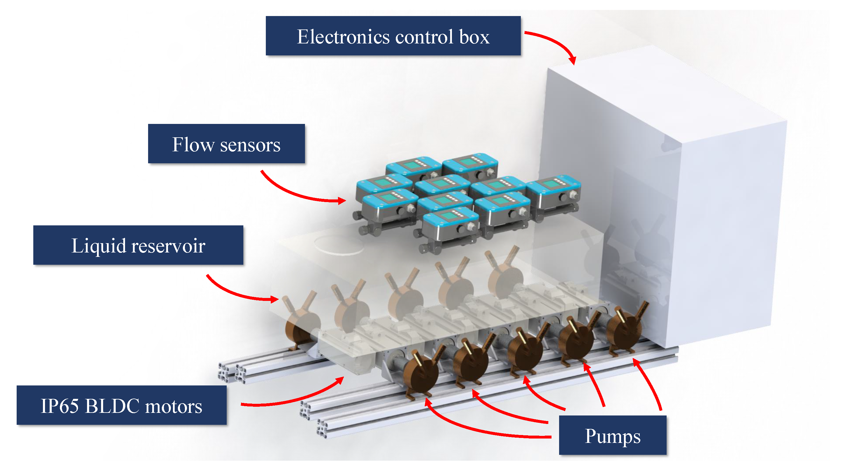
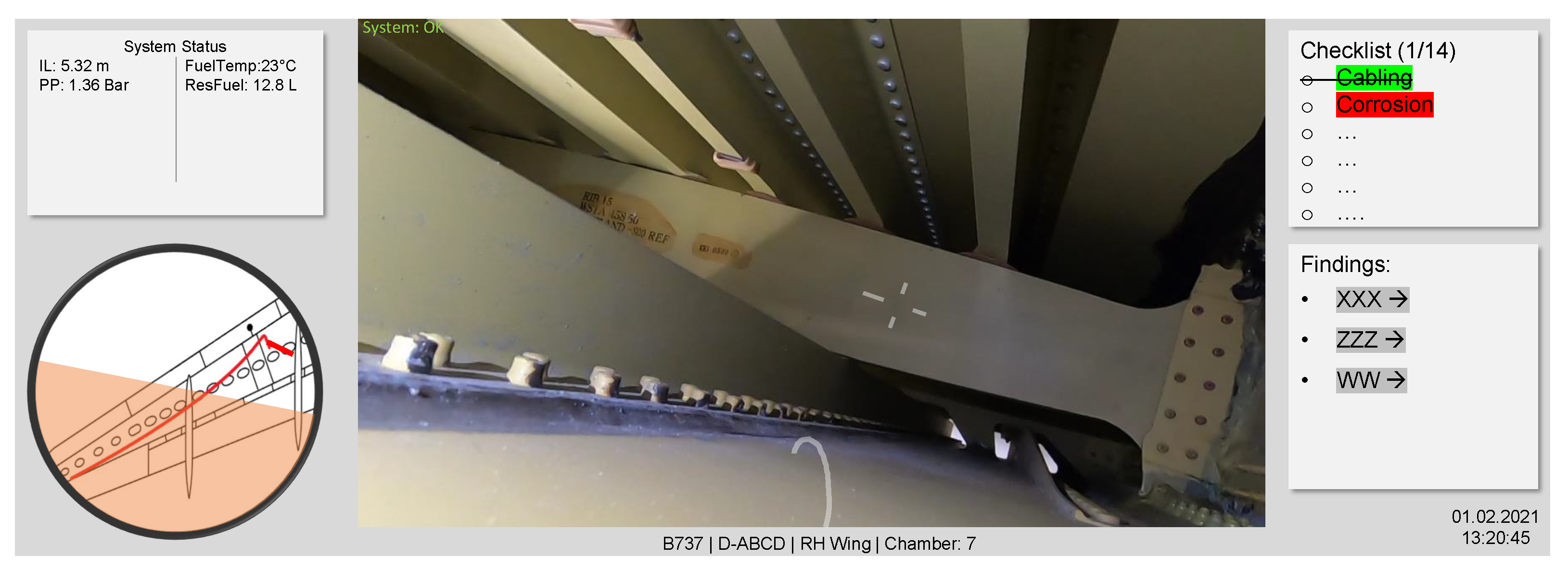
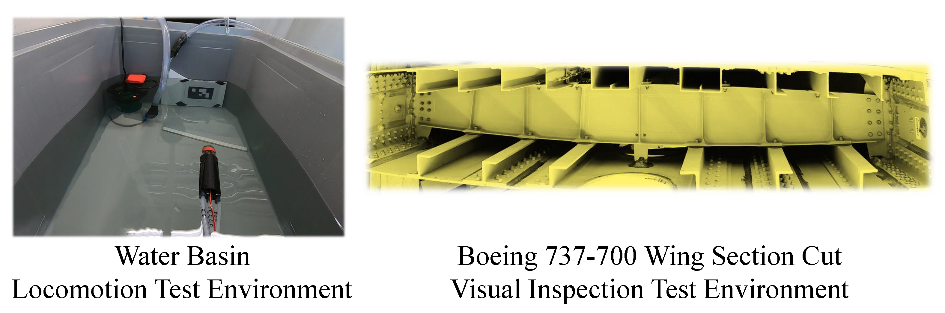
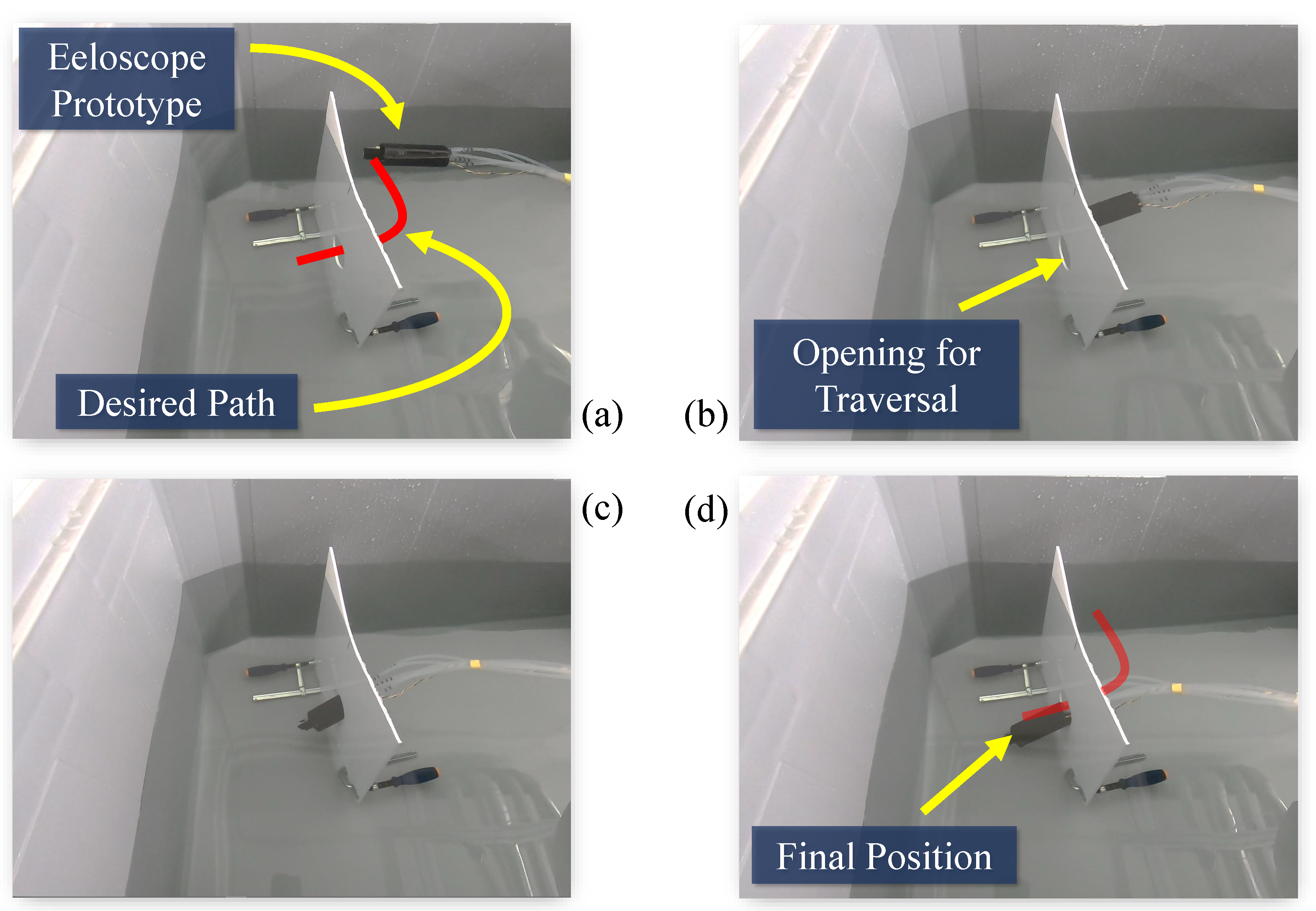
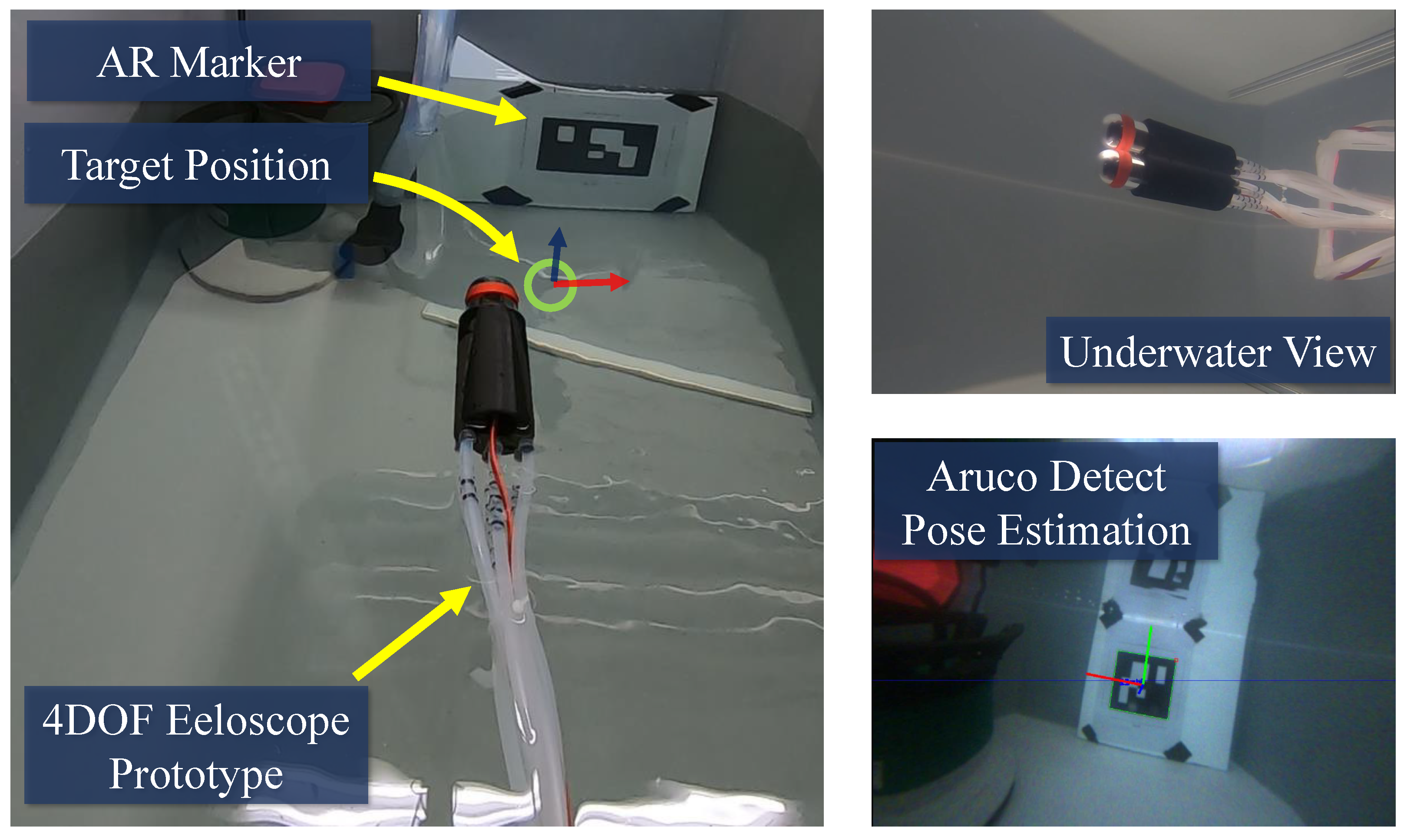
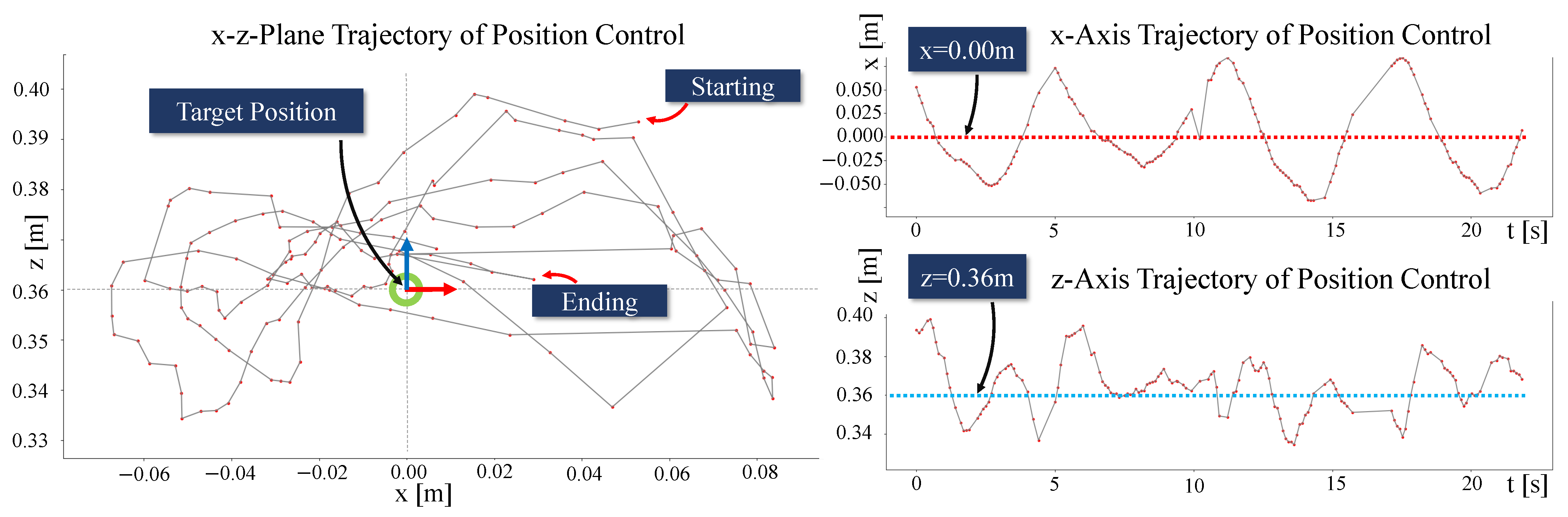
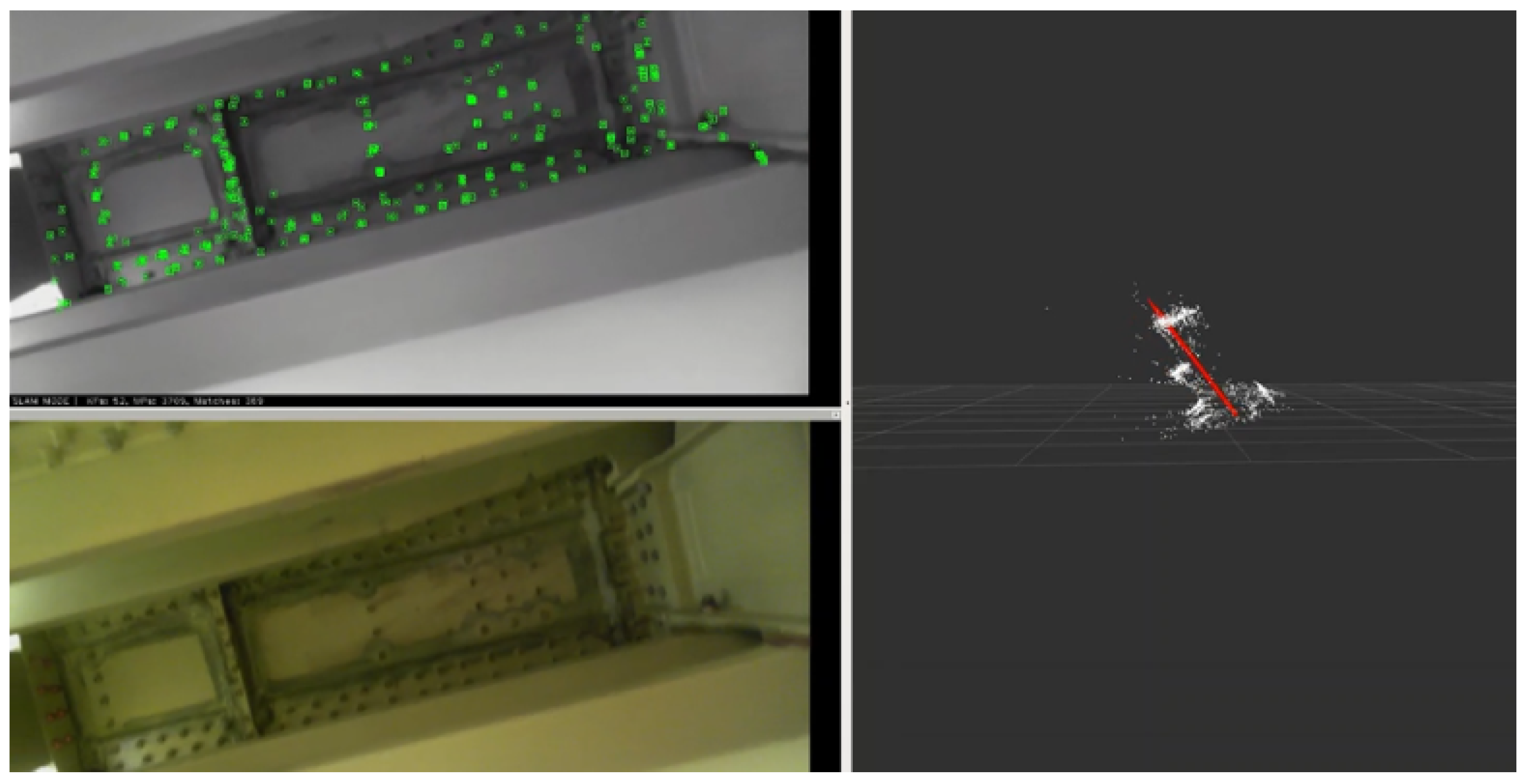
Figure 7.
State of R&D: Robotic Inspection Systems (Image sources: Anscombe et al. [19] © from OC Robotics, Gao et al. [20], Alatorre et al. [21], Brusell et al. [23], Hawkes et al. [24], © Festo SE & Co. KG [25], Christensen et al. [26], BIKE: © Waygate Technologies [27], Kelasidi et al. [28], © Sarcos Robotics [29], Eich et al. [30], Görner et al. [31], © Invert Robotics).

Figure 8.
Definition and Assessment of Abstract Basic Functions for Tank Inspection Process.

Figure 9.
Ideation: Expressions for Function `locomote in tank’.

Figure 10.
Basic Locomotion Design Variants.

Figure 11.
Conceptual visualization of a future fuel tank maintenance process. Therefore, a hose-like structure can be attached to the wing fuel tank from a working platform to insert an endoscopic probe.
Figure 11.
Conceptual visualization of a future fuel tank maintenance process. Therefore, a hose-like structure can be attached to the wing fuel tank from a working platform to insert an endoscopic probe.

Figure 12.
The Eeloscope can dive through the tank chambers using a diving technique propelled by a kerosene jet.
Figure 12.
The Eeloscope can dive through the tank chambers using a diving technique propelled by a kerosene jet.

Figure 13.
Demonstration of the Eeloscope concept prototype within an aircraft wing fuel tank section of a phased-out Boeing 737 at the DLR Institute of Maintenance, Repair and Overhaul. The cylindrical outer diameter is currently 50 mm, but could potentially be even reduced.
Figure 13.
Demonstration of the Eeloscope concept prototype within an aircraft wing fuel tank section of a phased-out Boeing 737 at the DLR Institute of Maintenance, Repair and Overhaul. The cylindrical outer diameter is currently 50 mm, but could potentially be even reduced.

Figure 14.
Routing of the channels to guide the propulsion liquid to the thruster nozzles.

Figure 15.
Illustration of the basic motion capabilities for translation and rotation in cartesian space.
Figure 15.
Illustration of the basic motion capabilities for translation and rotation in cartesian space.

Figure 16.
The remote actuators are placed within a portable rig. For simplicity, the piping in between the reservoir, pumps and sensors is faded out.
Figure 16.
The remote actuators are placed within a portable rig. For simplicity, the piping in between the reservoir, pumps and sensors is faded out.

Figure 17.
The prototype for the human machine interface for controlling the endoscopic system and performing the general visual inspection is demonstrated using an empty fuel tank.
Figure 17.
The prototype for the human machine interface for controlling the endoscopic system and performing the general visual inspection is demonstrated using an empty fuel tank.

Figure 18.
The test environment for locomotion experiments and for the visual inspection experiments.
Figure 18.
The test environment for locomotion experiments and for the visual inspection experiments.

Figure 19.
Manual steering experiment for traversing a 6 cm hole within a vertical plane inside of a water basin. (a) Initial position of Eeloscope; (b) Eeloscope moving towards hole; (c) Eeloscope traversing hole; (d) Eeloscope reaching desired position
Figure 19.
Manual steering experiment for traversing a 6 cm hole within a vertical plane inside of a water basin. (a) Initial position of Eeloscope; (b) Eeloscope moving towards hole; (c) Eeloscope traversing hole; (d) Eeloscope reaching desired position

Figure 20.
Camera vision-based position control on the water surface using an ARUCO marker for pose estimation within a negative feedback controller.
Figure 20.
Camera vision-based position control on the water surface using an ARUCO marker for pose estimation within a negative feedback controller.

Figure 21.
Resulting path deviation relative to the x and z axis on the left graph. Individual deviations for x and z axis over time t in the right graphs.
Figure 21.
Resulting path deviation relative to the x and z axis on the left graph. Individual deviations for x and z axis over time t in the right graphs.

Figure 22.
Monocular visual SLAM applied within a phased-out Boeing 737-700 fuel tank section on the left. The right arrow indicates the pose of the camera sensor relatively to the landmarks.
Figure 22.
Monocular visual SLAM applied within a phased-out Boeing 737-700 fuel tank section on the left. The right arrow indicates the pose of the camera sensor relatively to the landmarks.

Publisher’s Note: MDPI stays neutral with regard to jurisdictional claims in published maps and institutional affiliations. |
© 2021 by the authors. Licensee MDPI, Basel, Switzerland. This article is an open access article distributed under the terms and conditions of the Creative Commons Attribution (CC BY) license (https://creativecommons.org/licenses/by/4.0/).
Share and Cite
MDPI and ACS Style
Heilemann, F.; Dadashi, A.; Wicke, K. Eeloscope—Towards a Novel Endoscopic System Enabling Digital Aircraft Fuel Tank Maintenance. Aerospace 2021, 8, 136. https://0-doi-org.brum.beds.ac.uk/10.3390/aerospace8050136
AMA Style
Heilemann F, Dadashi A, Wicke K. Eeloscope—Towards a Novel Endoscopic System Enabling Digital Aircraft Fuel Tank Maintenance. Aerospace. 2021; 8(5):136. https://0-doi-org.brum.beds.ac.uk/10.3390/aerospace8050136
Chicago/Turabian StyleHeilemann, Florian, Alireza Dadashi, and Kai Wicke. 2021. "Eeloscope—Towards a Novel Endoscopic System Enabling Digital Aircraft Fuel Tank Maintenance" Aerospace 8, no. 5: 136. https://0-doi-org.brum.beds.ac.uk/10.3390/aerospace8050136
Note that from the first issue of 2016, this journal uses article numbers instead of page numbers. See further details here.