
Challenges of Ablatively Cooled Hybrid Rockets for Satellites or Upper Stages


Department of Industrial Engineering, Università degli Studi di Padova, 35131 Padova, Italy
Aerospace 2021, 8(7), 190; https://0-doi-org.brum.beds.ac.uk/10.3390/aerospace8070190
Submission received: 31 May 2021
/
Revised: 4 July 2021
/
Accepted: 8 July 2021
/
Published: 14 July 2021
(This article belongs to the Special Issue Hybrid Rocket(Volume II))
Abstract
:Ablative-cooled hybrid rockets could potentially combine a similar versatility of a liquid propulsion system with a much simplified architecture. These characteristics make this kind of propulsion attractive, among others, for applications such as satellites and upper stages. In this paper, the use of hybrid rockets for those situations is reviewed. It is shown that, for a competitive implementation, several challenges need to be addressed, which are not the general ones often discussed in the hybrid literature. In particular, the optimal thrust to burning time ratio, which is often relatively low in liquid engines, has a deep impact on the grain geometry, that, in turn, must comply some constrains. The regression rate sometime needs to be tailored in order to avoid unreasonable grain shapes, with the consequence that the dimensional trends start to follow some sort of counter-intuitive behavior. The length to diameter ratio of the hybrid combustion chamber imposes some packaging issues in order to compact the whole propulsion system. Finally, the heat soak-back during long off phases between multiple burns could compromise the integrity of the case and of the solid fuel. Therefore, if the advantages of hybrid propulsion are to be exploited, the aspects mentioned in this paper shall be carefully considered and properly faced.
1. Introduction
Hybrid rocket propulsion has the potential to offer several advantages compared with current mature technologies as solid and liquid rockets, including simplicity, reliability, costs, safety, ease-of-use/production, and environmental friendliness [1].
In particular, hybrid rockets could provide a similar degree of flexibility in the thrust profile as a liquid engine (deep throttling and multiple stop-restart on demand) at a reduced complexity.
For these reasons, they have been proposed for several applications [2,3,4,5,6,7,8,9,10,11,12,13,14,15,16], including but not restricted to upper stages and satellites/spacecrafts, which are the specific subject of this paper. Reference [2] is a review of hybrid rocket status and several potential proposed applications of this technology written in the sixties, while [3] is a similar update version done recently that describes the major challenges in hybrid hockets and future applications of hybrid-propulsion systems, including the recent market of space tourism. Reference [4] focuses on the market perspective of paraffin-based hybrids, while reference [5] defines the most suitable applications for a near-term implementation considering hybrid rocket technology status. Reference [6] is a study of the most promising hybrid applications from a large company point of view, citing manned systems, small launchers, landers, and upper stages. Reference [7] is one of the multiple examples of the study of hybrid propulsion for sounding rockets. Reference [8] proposes the use of hybrid propulsion for an air-launched orbital vehicle. References [9,10] suggest two different hybrid architectures for the upper stages of small launch vehicles. Reference [11] describes a hybrid propulsion system for orbit raising applications while reference [12] proposes the use of hybrid propulsion to lower the orbit of a small satellite launched as a secondary payload from GTO [Geostationary Transfer Orbit] to LEO [Low Earth Orbit]. References [13,14] consider a hybrid motor for a small recoverable satellite. Reference [15] describes an alternative geometry hybrid rocket for spacecraft orbit transfer. Finally, reference [16] proposes a hybrid engine module for active space debris removal.
However, several challenges have prevented this kind of propulsion to reach operational status. The most cited are low regression rate, low combustion efficiency, instabilities, and mixture ratio shift [17,18,19,20]. Reference [17] underlines that, due to the previous issues, the hybrid technology available at the end of the previous century is not able to compete effectively with the consolidated liquid and solid ones. Reference [18] highlights the benefits of the increase in the regression rate, and reference [19] focuses on advanced fuels able to boost hybrid performance. Reference [20] is an example of modelling of hybrid rocket instabilities.
In the last decades, a lot of effort has been put into solving those issues, and only few examples of the most promising techniques are presented in the references [21,22,23,24,25,26,27,28]. Reference [21] is a review of the several ways proposed and studied to compensate or solve the low regression rate in hybrid rockets. Reference [22] describes the successful testing of high regressing paraffin-based fuels while reference [23] shows the flight testing of this solution. Reference [24] explores the use of diaphragms to increase hybrid performance, while references [25,26,27,28] study different aspects of swirling injection for the same purpose.
Nowadays, several groups have demonstrated good performance for low to medium scale demonstrators, which are compatible with the majority of expected thrusts for the applications considered in this paper.
In the following chapters, the use of hybrid propulsion for upper stages and satellites is reviewed and analyzed, showing some overlooked challenges other than the classical ones most frequently addressed in the literature, which must be considered for successful implementation of this technology.
Even if this is not a necessary condition, hybrid rockets are often ablatively cooled in order to keep the architecture as simple as possible and to exploit similarities with solid propellant combustion chambers [29], while liquid engines are today more often radiatively or regeneratively cooled (with few, more historical exceptions [29]). Thus, part of the problems highlighted in this paper are general for all hybrid rockets, while some others are specific to the ones that are ablatively cooled, which is often the case.
The rest of the paper is composed of four chapters. In the second chapter, the hybrid combustion chamber sizing is recalled and discussed. In the third chapter, the satellite case is presented while the fourth deals with upper stages. Finally, the conclusions are drawn.
2. Hybrid Rocket Combustion Chamber Sizing
In a previous paper by the author [30], some equations for single cylindrical port combustion chamber sizing and mission envelope were obtained and discussed. In particular, it was shown that the volume loading and the length of the fuel grain depend asymptotically on the ratio of the initial to final port diameter R. Consequently, while a minimum value of R (generally between 2 and 3) is necessary to achieve a good volume loading, much larger values do not provide major benefits; on the contrary, considering also the pre- and post-combustion chambers, sometimes the opposite occurs. Moreover, the maximum value of R can be limited by the root square of the ratio between the maximum and minimum allowable port fluxes, which also cannot be selected arbitrarily as constrained by phenomena such as flooding or chuffing, instabilities, and efficiency. This maximum ratio depends on the propellant combination and rocket design, particularly regarding the injection. Consequently, in [30] it was shown that while for large boosters or short burning times, the low regression rate of hybrid rockets is definitely a strong limitation; for the applications considered in this paper, sometimes the opposite could occur, namely, even the regression rate of classical polymeric fuels could be too high to be compatible with the imposed constraints.
In particular, the following scaling law was obtained:
which explicitly shows that high thrust and short burning time require high regression rates to achieve a sufficient value of R, but small sizes and long burning time necessitate a low regression rate in order to avoid passing the threshold on the maximum value of R.
This analysis highlights not only the importance to find solutions in order to enhance the regression rate for an efficient scale up of hybrid rockets but also the importance of tailoring the regression rate for specific mission requirements. Regression rate tailoring can be achieved in several ways, first of all with the selection of the fuel and corresponding additives [31], but also playing with the injection pattern, for example, by varying the swirl number [32]. Unfortunately, for some conditions, for instance, the ones typical of in-space liquid engines, no trivial solutions exist, and the hybrid should be designed with different parameters or discarded, as it will be discussed later on.
This paper will consider mainly single port hybrids with brief citations of the multiport case. Several other kinds of hybrid architectures have been proposed and tested [33] but they present several drawbacks and their technology readiness level is much lower; therefore, for the moment they are not taken into consideration as a near-term possibility.
For a single cylindrical port, it is possible to demonstrate that the maximum final grain diameter is related to the minimum allowable oxidizer flux. For a fixed external diameter, the length of the grain is minimized for the maximum volume loading, i.e., when the initial oxidizer flux is maximum, even if, above a certain value of R, the effect is asymptotic. Thus, if we consider the possibility to adjust the regression rate level in order to reach the maximum possible value of R and minimize the length of the motor, eq. 1 can be rewritten as:
considering that the initial diameter is proportional to the square root of the thrust, it is possible to write:
Consequently, the final diameter is a fixed multiple of the initial one:
From Equations (2) and (3), it is possible to determine the regression rate level needed to achieve the maximum possible packaging, i.e., Rmax:
As expected, for the same burning time, larger motors require higher regression rates in order to achieve the same volume loading. For too large motors and/or too short burning times, it is possible that Equation (4) cannot be satisfied, i.e., the regression rate level is not sufficient to guarantee not only Rmax but even the Rmin necessary for a good volume loading. This is the typical problem of boosters that is repeatedly discussed in the hybrid literature. However, in this paper, an often overlooked opposite situation is highlighted, which is typical of the application under consideration, i.e., satellites and upper stages. If the thrust is low and the burning time is very long, the value of a can result to be too low and incompatible with any of the classical polymeric fuels that have been successfully used for hybrid propulsion. On a few occasions, some fuels have been used with even lower regression rates (such as blocks of graphite) but without the same combustion performance.
The length of the grain can be calculated in the following way:
therefore, for a fixed diameter ratio R (equal to Rmax for maximum packaging) the length of the grain is proportional only to the burning time, not to the thrust of the motor. This result seems counter-intuitive, as in general it is expected that a larger motor is also longer. Moreover, for the same total impulse, an increase in the burning time should shorten the motor, not the opposite. Nevertheless, in the common literature, the regression rate level is considered as constant, while in this analysis the regression rate is tailored to achieve but not overcome Rmax. As already pointed out, this is not always possible at the two extremes of the range of allowable regression rate levels.
The physical meaning of this result is that, for the same burning time, in order to keep the diameter ratio equal to Rmax, two motors with different propellant masses (i.e., total impulse and thrust) will have the same length as the smaller motor needs to burn with a lower regression rate level (e.g., changing the fuel or the injection pattern) in order to keep the web thickness proportional to the smaller initial port diameter.
Finally, the length to diameter ratio for a fixed R is:
which, again leads to a counter-intuitive result, i.e., the length to diameter ratio increases with the burning time and decreases with the propellant mass or thrust. However, again, the effect is due to the hypothesis of regression rate tailoring; instead, for a fixed regression rate, the opposite occurs as expected. In conclusion, the previous analysis has been done to show that, on the contrary of boosters, which maximize the regression rate, for the applications considered in this paper (satellites and upper stages), where often the ratio between burning time and thrust could be significant, the regression rate level may need to be limited to avoid unreasonable grain shapes and/or motor initial and final parameters. The consequence of this regression rate limitation leads to a different (even opposite) behavior of the grain geometry with respect to motor global parameters such as thrust, burning time, and total impulse, affecting the packaging of the combustion chamber and the whole hybrid propulsion system.
3. Satellites and Spacecrafts
3.1. Current Status Quo
Satellites employ propulsion systems for several tasks, including orbit raising, orbit circularization, station-keeping and orbit control, collision avoidance, de-orbiting or transfer to a graveyard orbit, and so on.
Looking to the historical trend, it is possible to notice that both solid and liquid propulsion have been widely used, but liquid propulsion has become more and more dominant.
This fact has several explanations. The first one is by the fact that, thanks to its restartability, liquid propulsion can accomplish many of the aforementioned tasks with the same unit. On the contrary, a single burn solid rocket can perform only a single maneuver in a single shot. For this reason, solid rockets have been often employed as a kick stage for orbit circularization, but a liquid propulsion system is still required for the rest of the mission. Unified liquid propulsion systems that include both the main engine and the attitude thrusters fed by the same propellants have become more and more widespread in the last decades.
Moreover, the burning time of a solid motor is limited in a certain range due to design constraints of the grain and the ablative thermal protection system. Looking, for example, at the Northrop Grumman [USA] catalog [34] at the STARTM motor series, it is possible to note that, even with a certain level of data dispersion due to the different design requirements, the burning time of the solid motors tend to increase with the scale of the motor, from a dozen of seconds at few hundred newtons up to asymptotically reach a value around 100 s at dozens of kN. This implies that an increase in total impulse is necessarily related with an increase in motor thrust. On the contrary, the typical radiative in-space small liquid engine has virtually an unlimited firing time (on the order of hours), so it can provide a large total impulse at very low thrust. Liquid engines operate for a long burning time for several reasons: keep the engine and fluidic size/mass/cost/emitted heat at a minimum, limit the spacecraft acceleration, operate at low pressures with a benefit on the pressurization budget and chamber thermal loads without compromising the engine size.
Because of the low thrust of the liquid engine, the maneuvers can be performed with the solar panel deployed and an active attitude control system. On the contrary, the relatively high thrust solid rocket has been often used on spinning satellites with attached solar panels (at least during the fire). This second “rough” option has been employed more in the past on simpler systems while modern more complex satellites tend to prefer the first solution that is softer and more accurate.
3.2. Hybrid Analysis
It is interesting to analyze how the hybrid technologies place themselves in the same situation. Based on the previous thoughts and considering hybrid energy management capability, it is preferable to exploit the multiple burn possibility of the hybrid as this represent a significant benefit for the satellite mission flexibility.
The liquid propulsion system is the only one that has the degree of freedom to decouple thrust from the total impulse/burning time. The hybrid is limited by the previous scaling law, which provides a qualitatively similar trend of a solid rocket. This is particularly reinforced in the case of ablative cooling where another analogue scaling law can be defined with reference to nozzle throat erosion:
Again, for a fixed maximum tolerable relative nozzle erosion, larger motors can burn for longer times. Consequently, to provide larger total impulses, the hybrid needs to increase its thrust.
Regarding satellite propulsion, for the sake of clarity, we define three possible cases:
- The satellite/spacecraft is limited by a maximum allowable acceleration;
- No significant acceleration limits are considered;
- The satellite/spacecraft requires a minimum acceleration level for a specific maneuver.
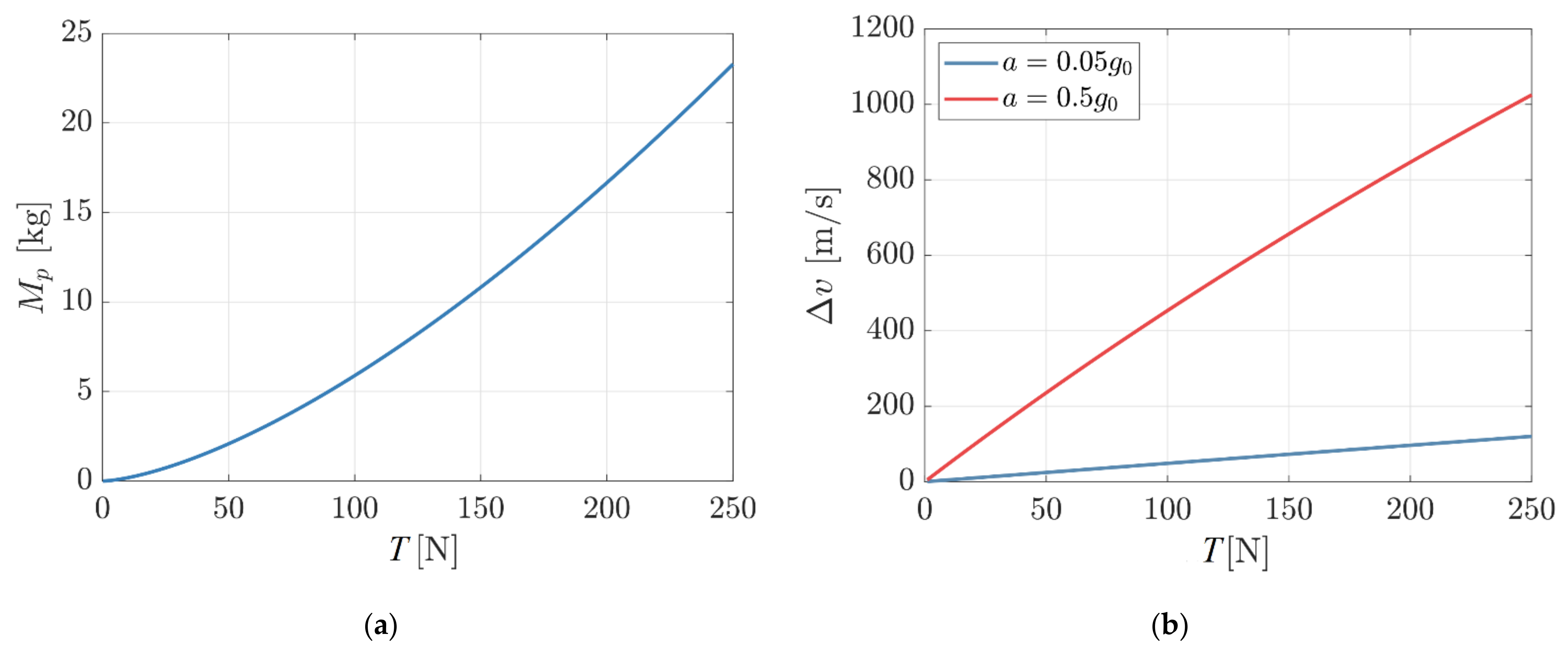
In the first case, the limit could be related to the attitude control system capabilities or by structural considerations of the appendices (e.g., deployable solar panels). For a certain satellite mass and maximum tolerable acceleration level, the maximum thrust is defined. The liquid propulsion system is the only one that can provide almost any total impulse for the selected thrust. Both solids and hybrids can provide only a certain level of total impulse for a specific thrust; consequently, if the acceleration limit is low, only a moderate velocity increment could be obtained. For a fixed acceleration, the thrust is proportional to the satellite mass while the total impulse is proportional to the product of the thrust and the burning time, with the latter that increases with the square root of the thrust for a fixed grain geometry. Consequently, as shown in Figure 1 from [30], the possible velocity increment for a hybrid is higher for larger satellites.
In the second case, even if no acceleration limits are considered, again the liquid engine will tend to be small in order to minimize the inert mass. On the contrary, the hybrid has to increase its thrust to provide larger total impulses, because of the lower limit of regression rate. For moderate velocity increments, the size and inert mass of the propulsion system have a lower impact on the whole system, so the hybrid could better exploit its advantages. For larger velocity increments, the small liquid (few hundreds N) should be compared with a hybrid providing a thrust even one or two orders of magnitude larger (up to dozen kN). For such difference in thrust, it is difficult for the hybrid propulsion system to compete with the liquid one in terms of inert mass and size, even including the propellant tanks due to the large combustion chamber. For large ΔV, the sensitivity on inert mass is high, so the penalty becomes much more relevant. Packaging is also more difficult, as the combustion chamber is long and bulky and for the reasons aforementioned, needs to fulfill some geometrical constraints that determine a limited range of possible shapes. Liquid propellant tanks are more flexible in this regard. In order to reduce the length to diameter ratio of the combustion chamber, it is worth mentioning an unconventional hybrid configuration, the so-called vortex pancake [15]. However, as in this case the thrust is proportional to the frontal surface area and the grain height is proportional to the burning time, and for a reasonable design, this configuration is limited to moderate velocity increments.
Solid rockets have also to increase their thrust with the total impulse; however, their density impulse tends to be far superior to hybrids, particularly when the whole system is considered, as the solid lacks the need for plumbing, valves, and the pressurization system as well as employing denser propellants. Moreover, the nozzle size can be kept reasonable with a moderately high chamber pressure. The small liquid engine operates at lower pressures to minimize the mass of the pressurization system. The hybrid falls in an uncomfortable position where an increase in pressure will burden the pressurization system while its reduction will enlarge the nozzle size (which is not an issue for the much smaller liquid).
An example of such a situation is presented in [11] where a large hybrid is designed for orbit raising. Another example of the use of a hybrid is described in [12] where a small motor is operated cumulatively for less than 90 s to perform several maneuvers to transfer a secondary small satellite from a GTO to LEO orbit. A detailed trajectory analysis is missing so it is not known if the same set of maneuvers could be performed by a smaller (liquid) thruster operating for longer periods. The alternative geometry hybrid rocket for spacecraft orbit transfer studied in [15] is proposed for moderate ΔV and imposes a relatively high acceleration on the small satellite, questioning again the trade-off against a lower thrust liquid engine. In [16], the hybrid engine module for active space debris removal is used on a large spacecraft for a ΔV around 500 m/s and thus, as shown in the previous analysis, the increased scale and not too high, and ΔV helps the competitiveness of the hybrid solution.
The third situation is probably the rarest, that is when the spacecraft needs a certain minimum acceleration and therefore thrust. This could happen in particular for exploration missions or other situations where a capture or re-entry burn must be performed in a fixed amount of time to fulfill the trajectory needs (as in the case of the SARA platform Universidade de Brasília, Brazil, [13,14]).
In this case where the thrust of the hybrid and the liquid are the same, the usual comparison of hybrids vs. liquids found in the classical literature is valid.
In conclusion, the hybrid rocket is much more competitive against a liquid propulsion system for satellites or spacecrafts when the velocity increment is relatively small or the maneuver requires a significant acceleration, i.e., thrust (in satellites terms).
Compared to solids, the need for multiple ignitions or throttleability is mandatory to justify the hybrid adoption, unless the requirements are relaxed and other aspects are a priority (e.g., safety, costs…).
3.3. Heat Soak-Back and Fuel Issue for Satellites
The general simplicity feature attributed to hybrids is also dependent on the typical use of an ablative nozzle and a simple combustion chamber design. The fuel itself behaves as an effective “free” ablative protection of the combustion chamber. However, when the motor is shut down, a significant heat soak-back from the nozzle occurs. This is not such a big issue for solid rockets that are typically used only for a single shot or for few pulses not so far from each other in some military applications. The problem becomes much more relevant in the case of a small hybrid motor for satellites that has to perform several maneuvers far apart from each other (e.g., orbit raising, de-orbiting…). Liquid engines have also to face the heat soak-back issue; however, they have a metallic construction that can withstand high temperatures and are decoupled from the rest of the propulsion system through specific devices (e.g., spacers, heat shields). The propellants are stored in separate tanks at room-temperature. On the contrary, in the hybrid, the fuel is placed inside the combustion chamber and could melt or be damaged by the heat soak-back. The chamber case itself is generally not designed to withstand high temperatures. Some heat can be radiatively dissipated slowly through the divergent part of the nozzle; however, the thermal design should have a sufficient heat sink/thermal barrier to prevent that while the case and/or the fuel integrity are jeopardized. The very low thermal conductivity and melting temperature of typical plastic fuels prevent the use of the remaining fuel mass for the following burns as a heat sink, since the heat will damage the fuel near the interfaces without penetrating significantly in the bulk of the fuel. In the case of fuels doped with solid particles (such as carbon or metals), the increased conductivity and density could partially help, but probably not in a decisive way. Doped fuels can also have a higher radiative heat transfer during the burn, which in turns influence the heat soak-back. Moreover, in case some hot particles are not fully expelled with the gaseous products from the nozzle, they could negatively influence the post-burn heat transfer inside the combustion chamber.
The solution to this specific issue, namely, the long waiting times between multiple burns could bring important additional mass and/or costs. Again, the impact of this issue is less severe for moderate ΔV. A more detailed discussion is presented in [29]. The problem can be partially alleviated in case of satellite propulsion, where often a single maneuver can be split in multiple steps if every single burn (except the last) is limited to a maximum fraction of the total impulse, reducing the amount of heat accumulated at the end of each burn.
4. Upper Stages
4.1. Current Status Quo
Upper stages are used in launch vehicles to provide the last part of the ΔV necessary to put the payload into orbit. Compared to booster stages, the engines used in the upper stages have a lower thrust (except when the lower stage uses a cluster of the same engine such as in the RocketLab Electron [USA-NZ] or SpaceX Falcon 9 [USA]) and often burn for a longer time.
Two main configurations can be recognized, one where the last stage provides a significant fraction of the ΔV required to reach orbit and has to overcome a certain degree of gravity losses (less than the booster stages as the flight path angle is more horizontal), the other when the upper stage has on top another smaller stage that behaves as a final space tug that is ignited in orbit or almost there to place the payload in the final orbit.
The larger upper stage thrust to weight ratio depends on a trade-off between engine weight/size and gravity losses. The ablative-cooled medium pressure (generally between 30 to 80 bars) solid rocket motors for upper stages generally optimize at the burning time between 60 to 120 s [34].
On the contrary, liquid engines are much more sensitive to thrust and tend to optimize at longer burning times (few hundreds of seconds). Chamber pressure can vary a lot, from very low values in smaller pressure-fed engines to moderate values in expander cycles to very high values in large pump-fed propulsion systems. The majority of the liquid engines are regeneratively cooled, except for some operating at low pressures that are ablatively cooled.
The space tug does not require a significant thrust as gravity losses are minimal during Hohmann transfers between different orbits. For this reason, these kinds of stages have a very low thrust to weight ratio, using relatively small liquid engines (compared with the total propellant mass) burning for very long times (several hundreds or even thousands of seconds). This solution provides a very low acceleration and high accuracy and is also more suitable for multiple maneuvers and higher orbits (i.e., total ΔV) up to GTO/GEO. Examples are the Russian space tugs (Khrunichev State Research and Production Space Center Briz, TsSKB-Progress Volga, NPO Lavochkin Fregat [Russia]) or the Curie and HyperCurie engines produced by Rocketlab [USA-NZ].
Regarding solid rocket-based launch vehicles, the first option is used with a direct injection trajectory as the solid motor must deliver all its total impulse in a single burn. This solution incurs in a ΔV penalty for higher orbits and is less precise due to the high thrust and the uncertainty of the solid stage. At other times, a small re-ignitable liquid stage is placed on top of the large solid stage for precise injection and a more efficient trajectory (e.g., AVIO [Italy] Vega with AVUM [Attitude and Vernier Upper Module], Northrop Grumman [USA] Pegasus + HAPS [Hydrazine Auxiliary Propulsion System]).
The data for solid rockets tend to be easy to retrieve as the nominal motor total impulse is part of the motor design. On the contrary, for liquid engines, care must be taken to separate the burning time for which the motor is qualified and the burning time that will deplete all the propellant of the stage. The same liquid engine (for example, the RL-10) can provide very different burning times (from 400 up to over 1100 s) depending on the stage in which it is integrated. Moreover, sometimes a liquid engine is throttled down during the final part of orbit injection to improve accuracy and reduce acceleration as gravity losses becomes much lower. For this reason, the stage burning time does not always correspond to the total impulse divided the nominal thrust. However, the aim of this paper is not to report accurate data but to show the trends and determine how the hybrid solution will fit as a possible replacement.
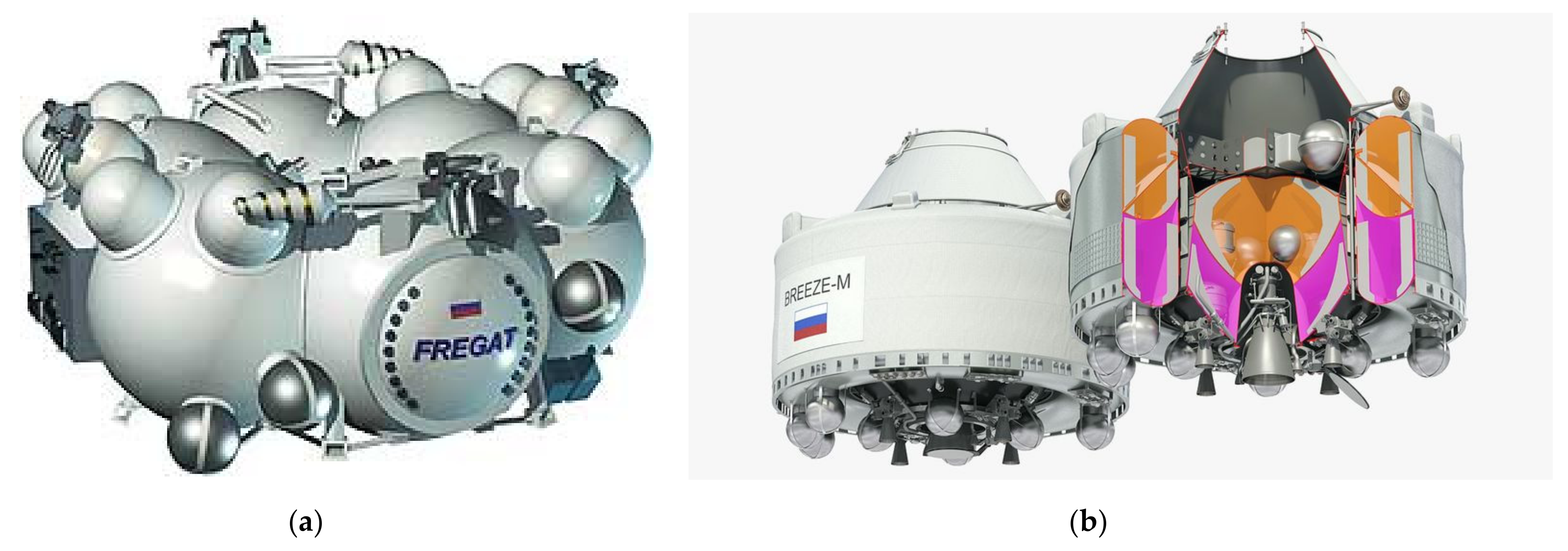
Regarding the total stage shape, it is important to underline that booster stages and upper stages often share the same diameter. Consequently, due to the large difference in propellant mass, booster stages have much higher stage L/D, or equivalently, upper stages have much lower L/D. The L/D of the booster stage range from 4 to higher than 12 [35] and tends to be compatible with a hybrid design until the regression rate is sufficient for the required thrust, otherwise a cluster of motors or a multiport design is necessary. The L/D of the upper stages is instead very low and can be even less than 1 for the Russian space tugs with toroidal-like arrangement (Figure 2).
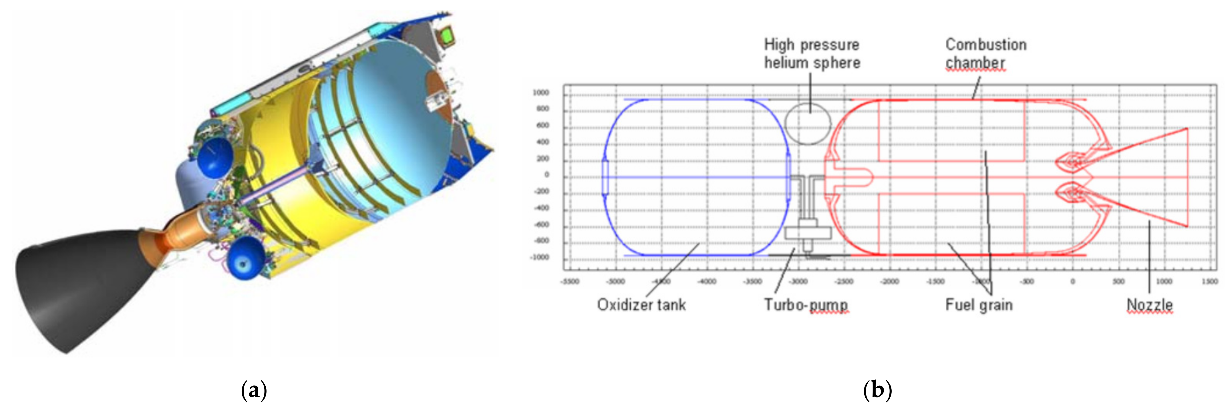
Liquid propelled upper stages with a more conventional serial arrangement are very mass efficient and still have a relatively low length to diameter ratio thanks to the flexibility in the liquid propellant storage tank design and the use of a common bulkhead (Figure 3).
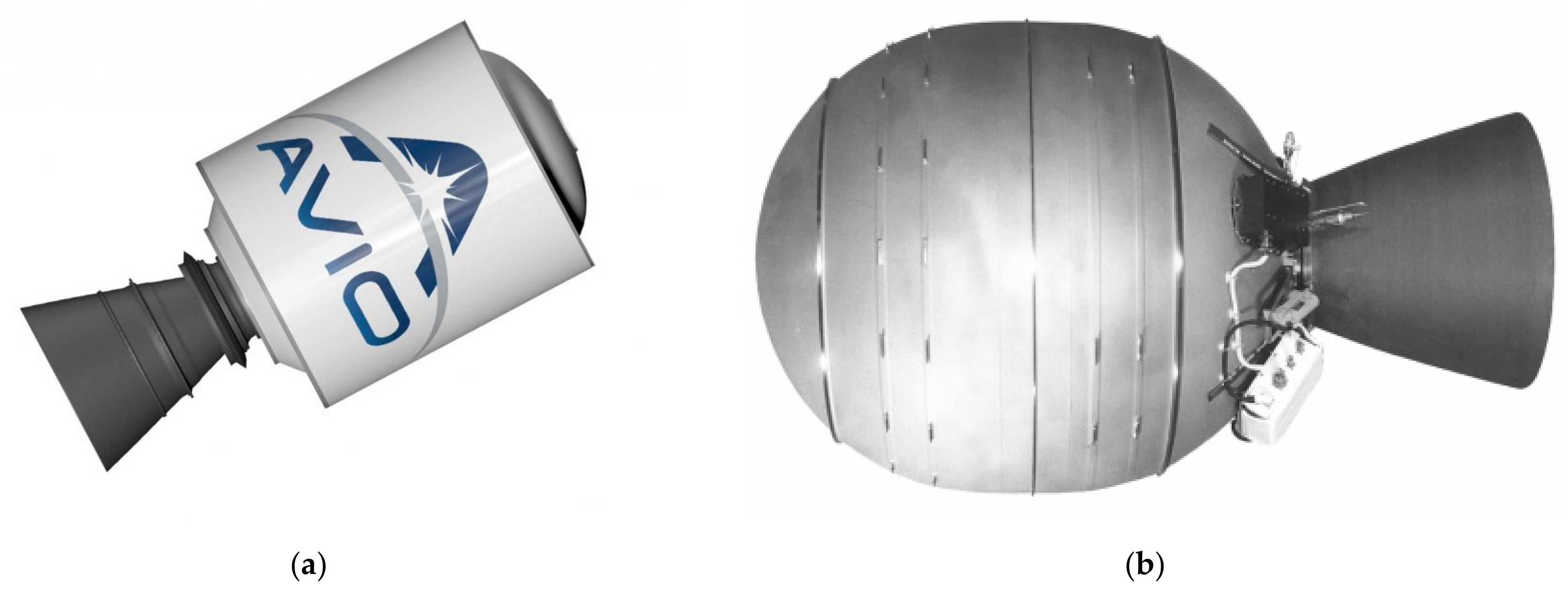
Solid rocket upper stages are very compact, sometimes using a spherical combustion chamber or otherwise a cylindrical chamber with a low length to diameter ratio and a high propellant mass fraction (Figure 4).
4.2. Hybrid Analysis
It is helpful to try to compare the geometrical characteristics of an equivalent hybrid upper stage. For the sake of simplicity, the motors of Table 1 and Table 2 have been considered, keeping the same thrust and burning time (i.e., total impulse). It is worth noting that the same total impulse does not provide the same payload performance as the latter is dependent also on inert mass and specific impulse of the stage. Moreover, the hybrid propulsion system could be better designed, optimizing the thrust and burning time to a different working point. It is still very useful to make a direct comparison to retrieve some interesting information.
Four propellant combinations have been considered: the combination between two oxidizers (LOX, [Liquid Oxygen], and hydrogen peroxide, H2O2) and two fuels, a high regressing one (such as paraffin wax) and a low regressing one (such as HDPE, [High Density PolyEthylene]). The specific impulse was fixed to 340 s for the LOX combinations and to 300 s for the H2O2 ones. The regression rate coefficients for LOX-paraffin have been defined as a = 0.117 and n = 0.62 [31] (with Gox in kg/m2 s and in mm/s); for H2O2–paraffin a = 0.15 and n = 0.5 [37]. The regression rate of the HDPE cases was fixed as five times lower than the paraffin one [31]. The paraffin fuel density was set to 930 kg/m3 while the HDPE density to 950 kg/m3. The mixture ratio for the LOX combinations was set equal to 2.7, while 7.5 was chosen for the H2O2 combinations. The initial oxidizer flux was fixed to 500 kg/m2·s. The internal diameter D0 was calculated from the oxidizer mass flow and initial mass flux while the external diameter was calculated with the following equation:
The length of the grain was calculated with the following equation:
Then, the diameter ratio R and the length to diameter ratio L/Df can be determined. The results are shown in the following Table 3, Table 4, Table 5 and Table 6.
From the tabulated results, it is possible to infer some considerations. The regression rate with H2O2 is lower than that with LOX, so the diameter ratio is higher with the latter. The length to diameter ratio of the grain is much lower for H2O2 thanks to its higher optimal mixture ratio and, consequently much lower fuel mass. For very long burning times (relative to the thrust level), the paraffin motors turn out to have too high diameter ratios and sometimes too low L/Df (the latter particularly for H2O2). On the contrary, reducing the regression rate with the HDPE fuel makes the diameter ratio more manageable but significantly increases the L/Df to values that are generally not acceptable.
Moreover, considering a simple ablative-cooling, burning times from few hundreds to thousands of seconds are considered almost impossible for the hybrid (some prototype ablative liquid engines from the 1960s achieved this at very low pressures and with significant fuel film cooling [29]).
The hybrid configuration gives reasonable results with paraffin for intermediate levels of thrust to burning time ratios, generally in between the values chosen for solids and liquids (as shown in the sizing presented in [9]).
However, the L/Df tabulated values refer to the grain, not to the whole stage. As the majority of the propellant is the oxidizer, it is easy to understand that, if the oxidizer is placed in a tank with the same diameter of the grain, the total length to diameter ratio will be more compatible with a booster than an upper stage. The only way to achieve a very low hybrid stage length to diameter ratio with a serial configuration is to use a cluster of combustion chambers or a multiport grain, but both solutions come with several drawbacks and have a significant impact on the inert mass of the stage, which is a fundamental parameter for an upper stage. Therefore, it is necessary to place the oxidizer in a different way. Three possible solutions have been presented by Karabeyoglu [9] as shown in Figure 5.
The simplest one is to use a larger spherical or cylindrical tank on top of the combustion chamber in a way similar to some liquid upper stages. Unfortunately, the hybrid combustion chamber is much longer than a liquid engine and this solution, which is structurally efficient at motor level, leaves a significant amount of unused space inside the stage. The total length becomes relevant and the stage stiffness could be an issue. An advantage could be that, because of a large clearance, stage separation could be placed near the tank, and the interstage could remain attached in the previous stage, allowing the propulsion system to fly “naked” with lower inert mass.
In the second case, a toroidal solution is employed. This solution makes the better use of the available space but is more complex and expensive to produce/assemble. The structural efficiency at the stage level is dependent on the specific design (type of toroid, alternative shapes, common walls, etc.) and, in common with the other configurations, from the scale of the system and the tank pressure level (in turn dependent on the pressurization choice, press-fed vs. pump-fed [38]).
In the third case, the propellant is placed in several tanks around the combustion chamber. This solution does not completely fill all the cylindrical space around the motor. Moreover, several tanks (with corresponding fluidic) of smaller volume tend to be heavier than a single tank of the same total volume [39], see Figure 6. In this case, there is no clearance, so the stage has to fly with its own case unless it is placed inside the fairing.
In all cases, the length to diameter ratio cannot reach the minimum levels of the competing technologies. In this regard, hydrogen peroxide turns out to be a better solution when very low L/D values are sought. Of course, the selection of the oxidizer is based on many other aspects, in particular the specific impulse advantage of LOX is much relevant for an upper stage, while the non-cryogenic storability of H2O2 is preferable when the orbital mission duration becomes relevant. Metal additives [40] can increase the specific impulse and fuel density but they generally also operate at lower optimal mixture ratios.
It is important to remember that, compared to a booster, an upper stage is much more sensitive to performance (i.e., inert mass and specific impulse) and has a lower impact on total costs, and this should be kept in mind in the selection of a hybrid solution instead of a conventional one and also in the way to design/configure it. Great care has to be placed on the structural mass, residuals [41], mixture ratio shift, and so on, as a too “rough” design will be competitive for a booster in terms of sensible cost reductions, but for an upper stage, could incur payload losses that completely jeopardize the relative potential minor (compared to the whole launcher) cost decrease.
4.3. Heat Soak-Back, Fuel Issue, and Orbit Insertion for Upper Stages
Again, the general simplicity feature attributed to hybrids is also dependent on the typical use of an ablative nozzle and a simple combustion chamber design. When hybrid rockets are proposed for upper stages, often the restartability feature is considered an advantage in order to perform the final orbit injection through a sort of Hohmann transfer. However, this aspect re-iterates the heat soak-back issue that is not present in ablative-cooled solid rocket upper stages, which perform a less efficient single burn direct injection. In particular, in a typical trajectory, the upper stage has to deliver almost all its total impulse in the first burn up to injection in a transfer orbit. In a pure Hohmann transfer, after a long coasting phase of roughly half an orbit (around 45 min), the circularization burn occurs. This second ignition consumes only the last few percent of the total propellant mass. This situation is very problematic, and in some way the worst possible, for several reasons. First, the first long burning time (almost the full duration) results in a considerable accumulation of heat and leaves only a small amount of residual fuel and thermal protection masses. In between the two burns, the very long coasting phase provides a substantial time for the heat to flow back to the combustion chamber case and fuel grain. Compared to the satellite case, here it is obviously not possible to split the first burn into small steps (perhaps it is possible for the space tug). Moreover, the already mentioned high sensitivity of upper stages to inert mass makes it difficult to solve the problem with the simple addition of significant added thermal protection mass. This issue is more relevant for small upper stages as the thermal transient is shorter and the relative size of thermal protection becomes larger. A more detailed discussion of the problem is presented in [29].
Finally, at constant thrust, the duration of the circularization burn tends to last only few seconds, with a detrimental effect on injection accuracy. A possible remedy is to exploit the potential hybrid throttleability at the cost of an increased complexity. However, throttling down a hybrid rocket motor produces a mixture ratio shift. This occurs under a very limited amount of the total impulse; the high upper stage sensitivity to specific impulse losses induces a non-negligible effect on the payload mass. Some more complex hybrid architectures are able to compensate the mixture ratio shift during throttling [42,43,44,45,46,47,48]. A simpler intermediate option that can be used for a pre-determined mission profile is the use of a concentric double fuel grain. Two different fuels burning at different rates can potentially compensate the mixture ratio shift during throttling. An example could be two paraffin-based fuel blends with different amounts of burning rate tailoring additives (such as polyethylene).
For instance, with n = 0.5, a throttling ratio of 4 can be achieved if the ratio between the mass flow production (i.e., the product of the regression rate times the density) of the two fuels is 2, and a throttling ratio of 9 can be achieved if the ratio between the two fuels is 3.
For the previous discussion about heat soak-back, an increased attention should be given to the thermomechanical properties of the second fuel.
In conclusion, performing an orbit injection through a Hohmann transfer using an ablative-cooled hybrid rocket upper stage without sensible loss of performance is a very demanding task that requires a careful evaluation and advanced design solutions.
5. Conclusions
Hybrid rocket motors have several positive features, one of these is the capability to be stopped/restarted multiple times. Another one is the intrinsic simplicity thanks to its single liquid feed system and, generally, the choice of an ablative cooled combustion chamber-nozzle assembly. These characteristics make this kind of propulsion attractive, among others, for applications such as satellites and upper stages. In this paper, the use of hybrid rockets for those situations has been reviewed.
First, it has been shown that, in contrast to boosters, which require maximization of the regression rate, for the applications considered here, where the ratio between the burning time and thrust could be significant, the regression rate may need to be limited to avoid unreasonable grain shapes and/or motor initial and final parameters. The consequence of this regression rate limitation leads to a different (even opposite) behavior of the grain geometry with respect to the motor global parameters such as thrust, burning time, and total impulse, affecting the packaging of the combustion chamber and, consequently, of the whole hybrid propulsion system.
It was demonstrated that a hybrid rocket is much more competitive against a liquid propulsion system for satellites or spacecrafts when the velocity increment is relatively small or the maneuver requires a significant acceleration, i.e., thrust (in satellites terms). Compared to solids, the need for multiple ignitions or throttle ability is needed to justify the hybrid adoption, unless the requirements are relaxed and other aspects are a priority (safety, costs). However, the heat soak-back during long off phases between multiple burns could compromise the integrity of the case and the solid fuel. Splitting each long burn into multiple shorter steps can partially alleviate the issue.
Regarding upper stages, hybrid rocket grain/combustion chamber design constraints impose some boundaries on the possible combinations of motor parameters such as thrust and burning time, which tend to optimize between liquids and solids. The length to diameter ratio of the hybrid propulsion system cannot match the minimum levels of the competing technologies, and to achieve compact designs, the possible oxidizer tank arrangements present some issues. Moreover, the difficulties to perform an orbital injection trough a Hohmann transfer have been highlighted. In fact, the circularization burn is very short and potentially imprecise (unless the motor is throttled down, but inducing a mixture ratio shift if not counteracted) and takes place after a long coasting phase where the heat soak-back from the almost full initial burn represents a significant threat for the combustion chamber and the little amount of fuel remaining. All the problems are exacerbated by the high sensitivity of upper stages to performance.
The discussion presented here does not preclude the use of (ablatively cooled) hybrid propulsion for these applications but underlines that a careful evaluation should be undertaken before and after the hybrid selection.
Funding
This research received no external funding.
Institutional Review Board Statement
Not applicable.
Informed Consent Statement
Not applicable.
Data Availability Statement
Not applicable.
Conflicts of Interest
The author declares no conflict of interest.
Nomenclature
| a, n | regression rate law coefficients |
| D0 | initial port diameter |
| Df | final port diameter |
| Dt | nozzle throat diameter |
| nozzle throat erosion rate | |
| G0 | initial port oxidizer mass flux |
| Gox | port oxidizer mass flux |
| Gmax | maximum (initial) port oxidizer mass flux |
| Itot | total impulse |
| L | fuel length |
| oxidizer mass flow | |
| pc | chamber pressure |
| fuel regression rate | |
| R | diameter ratio |
| Rmin | minimum diameter ratio |
| Rmax | maximum diameter ratio |
| tb | burning time |
| T | thrust |
| Vfuel | fuel grain volume |
| ΔV | spacecraft velocity increment |
References
- Altman, D.; Holzman, A. Overview and history of hybrid rocket propulsion. In Fundamentals of Hybrid Rocket Combustion and Propulsion; Chiaverini, M.J., Kuo, K.K., Eds.; American Institute of Aeronautics and Astronautics: Reston, VA, USA, 2007; Volume 218, pp. 1–36. [Google Scholar]
- Ordahl, D.D.; Rains, W.A. Recent Developments and Current Status of Hybrid Rocket Propulsion. J. Spacecr. Rocket. 1965, 2, 923–926. [Google Scholar] [CrossRef]
- Kuo, K.K.; Chiaverini, M.J. Challenges of hybrid rocket propulsion in the 21st century. In Fundamentals of Hybrid Rocket Combustion and Propulsion; Chiaverini, M.J., Kuo, K.K., Eds.; American Institute of Aeronautics and Astronautics: Reston, VA, USA, 2007; Volume 218, pp. 593–638. [Google Scholar]
- Mazzetti, A.; Merotto, L.; Pinarello, G. Paraffin-based hybrid rocket engines applications: A review and a market perspective. Acta Astronaut. 2016, 126, 286–297. [Google Scholar] [CrossRef]
- Barato, F.; Bellomo, N.; Pavarin, D. Integrated approach for hybrid rocket technology development. Acta Astronaut. 2016, 128, 257–261. [Google Scholar] [CrossRef]
- Martin, F.; Chapelle, A.; Orlandi, O.; Yvart, P. Hybrid propulsion systems for future space applications; AIAA Paper 2010–6633. In Proceedings of the 46th AIAA/ASME/SAE/ASEE Joint Propulsion Conference and Exhibit, Nashville, TN, USA, 25–28 July 2010. [Google Scholar]
- Barato, F.; Ghilardi, M.; Santi, M.; Pavarin, D. Numerical optimization of hybrid sounding rockets through coupled motor trajectory simulation; AIAA Paper 2016–4749. In Proceedings of the 52nd AIAA/ASME/SAE/ASEE Joint Propulsion Conference & Exhibit, Salt Lake City, UT, USA, 25–27 July 2016. [Google Scholar]
- Karabeyoglu, M.A.; Falconer, T.; Cantwell, B.J.; Stevens, J. Design of an orbital hybrid rocket vehicle launched from Canberra Air Platform; AIAA Paper 2005–4096. In Proceedings of the 41st AIAA/ASME/SAE/ASEE Joint Propulsion Conference and Exhibit, Tucson, AZ, USA, 10–13 July 2005. [Google Scholar]
- Karabeyoglu, M.A.; Stevens, J.; Geyzel, D.; Cantwell, B. High performance hybrid upper stage motor; AIAA Paper 2011–6025. In Proceedings of the 47th AIAA/ASME/SAE/ASEE Joint Propulsion Conference and Exhibit, San Diego, CA, USA, 31 July–3 August 2011. [Google Scholar]
- Casalino, L.; Masseni, F.; Pastrone, D. Viability of an electrically driven pump-fed hybrid rocket for small launcher upper stages. Aerospace 2019, 6, 36. [Google Scholar] [CrossRef] [Green Version]
- Boman, N.; Ford, M. Design of a hybrid propulsion system for orbit raising applications. In Proceedings of the 2nd International Conference on Green Propellants for Space Propulsion (ESA SP-557), Chia Laguna, Italy, 7–8 June 2004; Wilson, A., Ed.; European Space Agency: Noordwijk, The Netherlands, 2004. [Google Scholar]
- Lengellé, G.; Foucaud, R.; Godon, J.C.; Heslouin, A.; Lecourt, R.; Maisonneuve, Y. Hybrid propulsion for small satellites analysis and tests; AIAA Paper 99–2321. In Proceedings of the 35th AIAA/ASME/SAE/ASEE Joint Propulsion Conference and Exhibit, Los Angeles, CA, USA, 20–24 June 1999. [Google Scholar]
- Da Cás, P.L.K.; Vilanova, C.Q.; Barcelos, M.N.D., Jr.; Veras, C.A.G. An optimized hybrid rocket motor for the SARA platform reentry system. J. Aerosp. Technol. Manag. 2012, 4, 317–330. [Google Scholar] [CrossRef] [Green Version]
- Vilanova, C.Q.; Da Cas, P.L.K.; Barcelos, M.N.D., Jr.; Veras, C.A.G. Multidisciplinary design optimization of a de-boost hybrid motor for the Brazilian recoverable satellite. In Proceedings of the 2nd International Conference on Engineering Optimization, Lisbon, Portugal, 6–9 September 2010. [Google Scholar]
- Gibbon, D.M.; Haag, G.S. Investigation of an Alternative Geometry Hybrid Rocket for Small Spacecraft Orbit Transfer; DTIC Technical Report, AD No. 393398; Surrey Satellite Technology: Surrey, UK, 2001. [Google Scholar]
- De Luca, L.; Bernelli-Zazzera, F.; Maggi, F.; Tadini, P.; Pardini, C.; Anselmo, L.; Belokonov, I. Active space debris removal by hybrid engine module. In Proceedings of the 63rd International Astronautical Congress (IAC), Naples, Italy, 1–5 October 2012. [Google Scholar]
- Wagner, K.R.; Schmucker, R.H. Hybrid rockets for space applications—A critical assessment; AIAA Paper 1992–3305. In Proceedings of the 28th AIAA/ASME/SAE/ASEE Joint Propulsion Conference and Exhibit, Nashville, TN, USA, 6–8 July1992. [Google Scholar]
- Casillas, E.D.; Shaeffer, C.W.; Trowbridge, J.C. Cost and performance payoffs inherent in increased fuel regression rates; AIAA Paper 1997–3081. In Proceedings of the AIAA/SAE/ASME/ASEE 33rd Joint Propulsion Conference and Exhibit, Seattle, WA, USA, 6–9 July 1997. [Google Scholar]
- Orlandi, O.; Theil, D.; Saramago, J.; Amand, P.G.; Dauch, F.; Gautier, P. Various challenging aspects of hybrid propulsion. Prog. Propuls. Phys. 2011, 2, 375–388. [Google Scholar]
- Barato, F.; Bellomo, N.; Faenza, M.; Lazzarin, M.; Bettella, A.; Pavarin, D. Numerical model to analyze transient behavior and instabilities on hybrid rocket motors. J. Propuls. Power 2015, 31, 643–653. [Google Scholar] [CrossRef]
- Pastrone, D. Approaches to low fuel regression rate in hybrid rocket engines. Int. J. Aerosp. Eng. 2012, XX, 1–12. [Google Scholar] [CrossRef] [Green Version]
- Karabeyoglu, M.A.; Zilliac, G.; Cantwell, B.J.; De Zilwa, S.; Castellucci, P. Scale-up tests of high regression rate paraffin-based hybrid rocket fuels. J. Propuls. Power 2004, 20, 1037–1045. [Google Scholar] [CrossRef]
- Kobald, M.; Fischer, U.; Tomilin, K.; Petrarolo, A.; Schmierer, C. Hybrid experimental rocket Stuttgart: A low-cost technology demonstrator. J. Spacecr. Rocket. 2018, 55, 484–500. [Google Scholar] [CrossRef]
- Bellomo, N.; Lazzarin, M.; Barato, F.; Bettella, A.; Pavarin, D.; Grosse, M. Investigation of effect of diaphragms on the efficiency of hybrid rockets. J. Propuls. Power 2014, 30, 175–185. [Google Scholar] [CrossRef]
- Bellomo, N.; Barato, F.; Faenza, M.; Lazzarin, M.; Bettella, A.; Pavarin, D. Numerical and experimental investigation of unidirectional vortex injection in hybrid rocket engines rockets. J. Propuls. Power 2013, 29, 1097–1113. [Google Scholar] [CrossRef]
- Paccagnella, E.; Barato, F.; Pavarin, D.; Karabeyoğlu, M.A. Scaling Parameters of swirling oxidizer injection in hybrid rocket motors. J. Propuls. Power 2017, 33, 1378–1394. [Google Scholar] [CrossRef]
- Ronningen, J.E.; Husdal, J. Nammo Hybrid Rocket Propulsion TRL Improvement Program; AIAA Paper 2012–4311. In Proceedings of the 48th AIAA/ASME/SAE/ASEE Joint Propulsion Conference and Exhibit, Atlanta, GA, USA, 30 July 2012–1 August 2012. [Google Scholar]
- Ruffin, A.; Paccagnella, E.; Santi, M.; Barato, F.; Pavarin, D. Real-time deep throttling tests of a hydrogen peroxide hybrid rocket motor; AIAA 2019–4266. In Proceedings of the AIAA Propulsion and Energy 2019 Forum, Indianapolis, IN, USA, 19–22 August 2019. [Google Scholar]
- Barato, F.; Paccagnella, E.; Franco, M.; Pavarin, D. Numerical analyses of thermal protection design in hybrid rocket motors; AIAA 2020–3769. In Proceedings of the AIAA Propulsion and Energy 2020 Forum, Virtual Event. 24–28 August 2020. [Google Scholar]
- Barato, F.; Paccagnella, E.; Pavarin, D. Explicit analytical equations for single port hybrid rocket combustion chamber sizing. J. Propuls. Power 2020, 36, 6. [Google Scholar] [CrossRef]
- Karabeyoglu, M.A.; Cantwell, B.; Stevens, J. Evaluation of homologous series of normal-alkanes as hybrid rocket fuels; AIAA Paper 2005–3908. In Proceedings of the 41st AIAA/ASME/SAE/ASEE Joint Propulsion Conference and Exhibit, Tucson, AZ, USA, 10–13 July 2005. [Google Scholar]
- Franco, M.; Barato, F.; Paccagnella, E.; Santi, M.; Battiston, A.; Comazzetto, A.; Pavarin, D. Regression rate design tailoring through vortex injection in hybrid rocket motors. J. Spacecr. Rocket. 2020, 57, 278–290. [Google Scholar] [CrossRef]
- Chiaverini, M. Review of solid-fuel regression rate behavior in classical and nonclassical hybrid rocket motors. In Fundamentals of Hybrid Rocket Combustion and Propulsion; Chiaverini, M.J., Kuo, K.K., Eds.; American Institute of Aeronautics and Astronautics: Reston, VA, USA, 2007; Volume 218, pp. 37–126. [Google Scholar]
- Northrop Grumman. Propulsion Products Catalog. From Northrop Grumman Website. Approved for Public Release OSR No. 16-S-1432. Available online: https://www.northropgrumman.com/ (accessed on 5 April 2016).
- Kearney, D.; Joiner, K.F.; Gnau, M.P.; Casemore, M.A. Improvements to the marketability of hybrid propulsion technologies. In Proceedings of the AIAA SPACE 2007 Conference & Exposition, Long Beach, CA, USA, 18–20 September 2007. [Google Scholar]
- Bjelde, B.; Capozzoli, P.; Shotwell, G. The SpaceX Falcon 1 launch vehicle flight 3 results, future developments, and Falcon 9 evolution. In Proceedings of the 59th International Astronautical Congress, IAC-08-D2.1.03, Glasgow, Scotland, UK, 29 September–3 October 2008. [Google Scholar]
- Paccagnella, E.; Santi, M.; Ruffin, A.; Barato, F.; Pavarin, D.; Misté, G.; Venturelli, G.; Bellomo, N. Testing of a long-burning-time paraffin-based hybrid rocket motor. J. Propuls. Power 2019, 35, 432–442. [Google Scholar] [CrossRef]
- Barato, F.; Bettella, A.; Pavarin, D. Numerical investigation of pressure-fed solutions for paraffin based hybrid rocket motors; AIAA 2013–3897. In Proceedings of the 49th AIAA/ASME/SAE/ASEE Joint Propulsion Conference & Exhibit, San Jose, CA, USA, 14–17 July 2013. [Google Scholar]
- Delamata, A.; Besnard, E.; Bostwick, C. Fuel trade study for a nanosat launch vehicle upper stage; AIAA Paper 2010–6804. In Proceedings of the 46th AIAA/ASME/SAE/ASEE Joint Propulsion Conference and Exhibit, Nashville, TN, USA, 25–28 July 2010. [Google Scholar]
- Shark, S.; Sippel, T.; Son, S.; Heister, S.; Pourpoint, T. Theoretical performance analysis of metal hydride fuel additives for rocket propellant applications. In Proceedings of the 47th AIAA/ASME/SAE/ASEE Joint Propulsion Conference & Exhibit, San Diego, CA, USA, 31 July–3 August 2011. [Google Scholar]
- Barato, F.; Grosse, M.; Bettella, A. Hybrid rocket residuals: An overlooked topic; AIAA Paper 2014–3753. In Proceedings of the 50th AIAA/ASME/SAE/ASEE Joint Propulsion Conference & Exhibit, Cleveland, OH, USA, 28–30 July 2014. [Google Scholar]
- Barato, F.; Toson, E.; Pavarin, D. Variations and control of thrust and mixture ratio in hybrid rocket motors. Adv. Astronaut. Sci. Technol. 2021, 1–22. [Google Scholar] [CrossRef]
- Culver, D.W. Comparison of forward and aft injected hybrid rocket boosters. In Proceedings of the 27th AIAA/SAE/ASME Joint Propulsion Conference, Sacramento, CA, USA, 24–26 June 1991. [Google Scholar]
- Usuki, T.; Shimada, T. Improvement on thrust profile flexibility by oxidizer-to-fuel ratio feedback control in hybrid rocket. In Proceedings of the 66th International Astronautical Congress (IAC), Jerusalem, Israel, 12–16 October 2015. [Google Scholar]
- Ozawa, K.; Usuki, T.; Mishima, G.; Kitagawa, K.; Yamashita, M.; Mizuchi, M.; Katakami, K.; Maji, Y.; Aso, S.; Tani, Y. Static burning tests on a bread board model of altering-intensity swirling oxidizer-flow-type hybrid rocket engine. In Proceedings of the 52nd AIAA/SAE/ASEE Joint Propulsion Conference, Salt Lake City, UT, USA, 25–27 July 2016. [Google Scholar]
- Shimada, T.; Usuki, T. Conceptual study on flight demonstration of mixture-ratio-controlled throttling of hybrid rocket. In Proceedings of the 67th International Astronautical Congress (IAC), Guadalajara, Mexico, 26–30 September 2016. [Google Scholar]
- Ozawa, K.; Shimada, T. Flight performance simulations of vertical launched sounding rockets using altering-intensity swirling-oxidizer-flow type hybrid motors. In Proceedings of the 51st AIAA/SAE/ASEE Joint Propulsion Conference, Orlando, FL, USA, 27–29 July 2015. [Google Scholar]
- Ozawa, K.; Shimada, T. A theoretical study on throttle ranges of O/F controllable hybrid rocket propulsion systems. J. Fluid Sci. Technol. 2018, 13. [Google Scholar] [CrossRef] [Green Version]
Figure 1.
Examples of hybrid rocket design limits for satellites: (a) Propellant mass vs. thrust; (b) Velocity increment vs. thrust for different maximum allowable accelerations. Reprinted with permission from ref. [30]. Copyright 2020 American Institute of Aeronautics and Astronautics.
Figure 1.
Examples of hybrid rocket design limits for satellites: (a) Propellant mass vs. thrust; (b) Velocity increment vs. thrust for different maximum allowable accelerations. Reprinted with permission from ref. [30]. Copyright 2020 American Institute of Aeronautics and Astronautics.

Figure 2.
Examples of liquid propelled space tugs: (a) NPO Lavochkin Fregat (Soyuz/Zenit); (b) GKNPTs Khrunichev Briz-M (Proton). Note the extremely compact length to diameter ratio and the propellant tank arrangement. Copyright: publicly available pictures on the internet.
Figure 2.
Examples of liquid propelled space tugs: (a) NPO Lavochkin Fregat (Soyuz/Zenit); (b) GKNPTs Khrunichev Briz-M (Proton). Note the extremely compact length to diameter ratio and the propellant tank arrangement. Copyright: publicly available pictures on the internet.

Figure 3.
Examples of upper stages for small launch vehicles: (a) Liquid propelled SpaceX Falcon 1; (b) ORPHEE Hybrid Upper Stage proposal. Note the relatively high length to diameter ratio of the serial hybrid and the compact packaging of the common bulkhead liquid propellant design. (a) Reprinted with permission from ref. [36]. Copyright 2008 International Astronautical Federation. (b) Reprinted with permission from ref. [6]. Copyright 2010 American Institute of Aeronautics and Astronautics.

Figure 4.
Examples of solid rocket upper stages: (a) Avio Zefiro 9 (Vega); (b) Northrop Grumman Star 48 (Minotaur IV). Note the very compact length to diameter ratio. (a) Reprinted with permission from https://www.avio.com/ (accessed on 9 July 2021). Copyright 2021 Avio. (b) Reprinted with permission from ref. [34]. Copyright 2016 Northrop Grumman.

Figure 5.
Examples of hybrid upper stage arrangements: (a) Serial; (b) Toroidal; (c) Multiple tanks. Reprinted with permission from ref. [9]. Copyright 2011 American Institute of Aeronautics and Astronautics.
Figure 5.
Examples of hybrid upper stage arrangements: (a) Serial; (b) Toroidal; (c) Multiple tanks. Reprinted with permission from ref. [9]. Copyright 2011 American Institute of Aeronautics and Astronautics.

Figure 6.
Sampling of Scorpius® [USA] Composite Tanks (1.7 MPa MEOP (250 psi)): Volume vs. Tank mass factor. Reprinted with permission from ref. [39]. Copyright 2010 American Institute of Aeronautics and Astronautics.
Figure 6.
Sampling of Scorpius® [USA] Composite Tanks (1.7 MPa MEOP (250 psi)): Volume vs. Tank mass factor. Reprinted with permission from ref. [39]. Copyright 2010 American Institute of Aeronautics and Astronautics.


Table 1.
Selected operational upper stage engines (manufacturer/country).
| Model (Stage/Launcher) | Manufacturer | Country |
|---|---|---|
| RD-843 (AVUM-Vega) | Yuzhmash | Ukraine |
| 17D64 (Volga-Soyuz) | KB Melnikov | Russia |
| S5.98M (Briz-Proton) | KBKhM | Russia |
| S5.92 (Fregat-Zenit) | KBKhM | Russia |
| Rutherford (Electron) | RocketLab | USA-New Zealand |
| Aestus (Ariane 5) | Airbus Defence and Space | Europe |
| Kestrel (Falcon 1) | SpaceX | USA |
| Orion 38 (Pegasus) | Northrop Grumman | USA |
| HM7B (Ariane 5 ECA) | Snecma | France |
| RL10 (Centaur) | Aerojet Rocketdyne | USA |
| Vinci (Ariane 6) | ArianeGroup | Europe |
| Zefiro 9 (Vega) | Avio | Italy |
| Castor 30 (Antares) | Northrop Grumman | USA |
| Merlin 1D (Falcon 9) | SpaceX | USA |
Table 2.
Selected operational upper stage engines (motor parameters).
| Model (Stage/Launcher) | Thrust (kN) | Burning Time (s) |
|---|---|---|
| RD-843 (AVUM-Vega) | 2.45 | 300–600 |
| 17D64 (Volga-Soyuz) | 2.94 | 600 |
| S5.98M (Briz-Proton) | 19.6 | 3000 |
| S5.92 (Fregat-Zenit) | 19.85 | 1350 |
| Rutherford (Electron) | 26 | 258–373 |
| Aestus (Ariane 5) | 27 | 1170 |
| Kestrel (Falcon 1) | 31 | 378 |
| Orion 38 (Pegasus) | 32 | 67.7 |
| HM7B (Ariane 5 ECA) | 67 | 945 |
| RL10 (Centaur) | 110 | 400–700–1125 |
| Vinci (Ariane 6) | 180 | 900 |
| Zefiro 9 (Vega) | 314 | 117 |
| Castor 30 (Antares) | 300–500 | 127–156 |
| Merlin 1D (Falcon 9) | 934 | 397 |
Table 3.
Calculated equivalent hybrid grain design. LOX-paraffin case.
| Reference Model | Grain R = D0/Df | Grain L/Df |
|---|---|---|
| RD-843 (AVUM-Vega) | 11–15 | 1.3–1.1 |
| 17D64 (Volga-Soyuz) | 14 | 1.1 |
| S5.98M (Briz-Proton) | 19 | 0.9 |
| S5.92 (Fregat-Zenit) | 13 | 1.1 |
| Rutherford (Electron) | 5.9–7 | 2.1–1.9 |
| Aestus (Ariane 5) | 11.5 | 1.3 |
| Kestrel (Falcon 1) | 6.8 | 1.9 |
| Orion 38 (Pegasus) | 3.2 | 3.4 |
| HM7B (Ariane 5 ECA) | 8.5 | 1.6 |
| RL10 (Centaur) | 5.2–6.7–8.3 | 2.3–1.9–1.6 |
| Vinci (Ariane 6) | 6.7 | 1.9 |
| Zefiro 9 (Vega) | 2.5 | 4.1 |
| Castor 30 (Antares) | 2.6 | 4 |
| Merlin 1D (Falcon 9) | 3.3 | 3.3 |
Table 4.
Calculated equivalent hybrid grain design. H2O2-paraffin case.
| Reference Model | Grain R = D0/Df | Grain L/Df |
|---|---|---|
| RD-843 (AVUM-Vega) | 10–14 | 0.6–0.4 |
| 17D64 (Volga-Soyuz) | 13 | 0.4 |
| S5.98M (Briz-Proton) | 18 | 0.3 |
| S5.92 (Fregat-Zenit) | 12 | 0.4 |
| Rutherford (Electron) | 5–6 | 1.1–0.9 |
| Aestus (Ariane 5) | 10.5 | 0.5 |
| Kestrel (Falcon 1) | 5.8 | 0.9 |
| Orion 38 (Pegasus) | 2.6 | 2 |
| HM7B (Ariane 5 ECA) | 7.6 | 0.7 |
| RL10 (Centaur) | 4.4–5.8–7.3 | 1.2–0.9–0.7 |
| Vinci (Ariane 6) | 5.8 | 0.9 |
| Zefiro 9 (Vega) | 2.1 | 2.6 |
| Castor 30 (Antares) | 2.1 | 2.5 |
| Merlin 1D (Falcon 9) | 2.7 | 2 |
Table 5.
Calculated equivalent hybrid grain design. LOX-HDPE case.
| Reference Model | Grain R = D0/Df | Grain L/Df |
|---|---|---|
| RD-843 (AVUM-Vega) | 5–7 | 11–9 |
| 17D64 (Volga-Soyuz) | 6.8 | 9.2 |
| S5.98M (Briz-Proton) | 9.2 | 7.4 |
| S5.92 (Fregat-Zenit) | 6.4 | 9.7 |
| Rutherford (Electron) | 3–3.5 | 18–16 |
| Aestus (Ariane 5) | 5.6 | 11 |
| Kestrel (Falcon 1) | 3.4 | 16 |
| Orion 38 (Pegasus) | 1.75 | 27 |
| HM7B (Ariane 5 ECA) | 4.2 | 13 |
| RL10 (Centaur) | 2.7–3.3–4 | 19–16–14 |
| Vinci (Ariane 6) | 3.4 | 16 |
| Zefiro 9 (Vega) | 1.5 | 32 |
| Castor 30 (Antares) | 1.5 | 31 |
| Merlin 1D (Falcon 9) | 1.8 | 27 |
Table 6.
Calculated equivalent hybrid grain design. H2O2-HDPE case.
| Reference Model | Grain R = D0/Df | Grain L/Df |
|---|---|---|
| RD-843 (AVUM-Vega) | 4–6 | 6–4 |
| 17D64 (Volga-Soyuz) | 5.9 | 4.4 |
| S5.98M (Briz-Proton) | 8.2 | 3.2 |
| S5.92 (Fregat-Zenit) | 5.5 | 4.7 |
| Rutherford (Electron) | 2.4–2.8 | 11–9 |
| Aestus (Ariane 5) | 4.8 | 5.5 |
| Kestrel (Falcon 1) | 2.8 | 9.5 |
| Orion 38 (Pegasus) | 1.5 | 18 |
| HM7B (Ariane 5 ECA) | 3.5 | 7.5 |
| RL10 (Centaur) | 2.2–2.7–3.4 | 12–9.6–7.7 |
| Vinci (Ariane 6) | 2.7 | 9.5 |
| Zefiro 9 (Vega) | 1.3 | 20 |
| Castor 30 (Antares) | 1.3 | 20 |
| Merlin 1D (Falcon 9) | 1.5 | 17 |
Publisher’s Note: MDPI stays neutral with regard to jurisdictional claims in published maps and institutional affiliations. |
© 2021 by the author. Licensee MDPI, Basel, Switzerland. This article is an open access article distributed under the terms and conditions of the Creative Commons Attribution (CC BY) license (https://creativecommons.org/licenses/by/4.0/).
Share and Cite
MDPI and ACS Style
Barato, F. Challenges of Ablatively Cooled Hybrid Rockets for Satellites or Upper Stages. Aerospace 2021, 8, 190. https://0-doi-org.brum.beds.ac.uk/10.3390/aerospace8070190
AMA Style
Barato F. Challenges of Ablatively Cooled Hybrid Rockets for Satellites or Upper Stages. Aerospace. 2021; 8(7):190. https://0-doi-org.brum.beds.ac.uk/10.3390/aerospace8070190
Chicago/Turabian StyleBarato, Francesco. 2021. "Challenges of Ablatively Cooled Hybrid Rockets for Satellites or Upper Stages" Aerospace 8, no. 7: 190. https://0-doi-org.brum.beds.ac.uk/10.3390/aerospace8070190
Note that from the first issue of 2016, this journal uses article numbers instead of page numbers. See further details here.