
Experimental CanSat Platform for Functional Verification of Burn Wire Triggering-Based Holding and Release Mechanisms


1
Space Technology Synthesis Laboratory, Department of Smart Vehicle System Engineering, Chosun University, 309 Pilmun-daero, Dong-gu, Gwangju 61452, Korea
2
Korea Astronomy and Space Science Institute, 776 Daedeokdae-ro, Yuseong-gu, Daejeon 34055, Korea
*
Author to whom correspondence should be addressed.
Aerospace 2021, 8(7), 192; https://0-doi-org.brum.beds.ac.uk/10.3390/aerospace8070192
Submission received: 3 June 2021
/
Revised: 1 July 2021
/
Accepted: 13 July 2021
/
Published: 16 July 2021
(This article belongs to the Special Issue Vibration Control for Space Application)
Abstract
:In this study, we present the Diverse Holding and Release Mechanism Can Satellite (DHRM CanSat) platform developed by the Space Technology Synthesis Laboratory (STSL) at Chosun University, South Korea. This platform focuses on several types of holding and release mechanisms (HRMs) for application in deployable appendages of nanosatellites. The objectives of the DHRM CanSat mission are to demonstrate the design effectiveness and functionality of the three newly proposed HRMs based on the burn wire triggering method, i.e., the pogo pin-type HRM, separation nut-type HRM, and Velcro tape-type HRM, which were implemented on deployable dummy solar panels of the CanSat. The proposed mechanisms have many advantages, including a high holding capability, simultaneous constraints in multi-plane directions, and simplicity of handling. Additionally, each mechanism has distinctive features, such as spring-loaded pins to initiate deployment, a plate with a thread as a nut for a high holding capability, and a hook and loop fastener for easy access to subsystems of the satellite without releasing the holding constraint. The design effectiveness and functional performance of the proposed mechanisms were demonstrated through an actual flight test of the DHRM CanSat launched by a model rocket.
1. Introduction
A can satellite (CanSat) is a pico-class miniaturized satellite with a mass of less than 1 kg that is integrated into a can-shaped structure, with approximately the radius and height being less than 10 cm and 20 cm, respectively [1]. CanSat platforms have been widely adopted for project-based learning programs because they provide a unique opportunity to gain practical experience in space engineering during the development process in several key aspects, such as, design, fabrication, testing, and mission execution. In principle, a CanSat performs its dedicated mission while gliding from an altitude of several hundred meters using an equipped parachute launched by a model rocket or balloon. In recent years, the performance enhancement and miniaturization of electrical components have improved the mission capability of CanSats to perform various tasks, such as atmospheric measurements [2,3], sub-orbital experiments [4], and demonstration of space-related technologies [5,6,7,8]. For instance, Kizilkaya et al. [2] proposed a descent control system that helps a sensor payload travel through a Martian atmosphere and sample the in situ atmospheric composition during the CanSat descent. Oh et al. [5] developed a CanSat technology demonstration called “Smart Call from the Sky” (SCSky), which demonstrated the effectiveness of a shape memory alloy (SMA) wire actuator-based mechanism for operating an onboard smartphone via telecommands from the ground station. Through the CanSat platform, Chae and Oh [6] demonstrated the feasibility and effectiveness of solar, wind, and piezoelectric energy-harvesting systems for enhancing the power generation capability of spacecraft, particularly for CubeSats, which have a restricted size and available area for the installation of solar cells.
In 2018, the Space Technology Synthesis Laboratory (STSL) [9] of Chosun University developed a Diverse Holding and Release Mechanism Can Satellite (DHRM CanSat) as part of its annual research project series [10] to compete in the 2018 national-level CanSat competition hosted by the Satellite Technology Research Center (SaTReC), which is financially supported by the Ministry of Science and ICT (MSIT) of South Korea. The DHRM CanSat has four deployable dummy solar panels for the functional validation of the proposed optimized versions of the burn wire triggering-based HRMs, i.e., the pogo pin-type HRM, the separation nut-type HRM, and the Velcro tape-type HRM. The basic working principle of the HRMs is based on a burn wire triggering release mechanism, which has several advantages, such as an increased holding capability, simultaneous constraint in multi-plane directions, and simplicity of handling during the tightening process of the Dyneema wire, that help overcome the limitations of the conventional wire cutting release mechanisms. Furthermore, each mechanism has its own inherent features. The pogo pin-type HRM uses spring-loaded pogo pins to provide multiple functions, including an electrical power interface for mechanism activation, separation springs to initiate solar panel deployment, and acting as a status switch to determine the solar panel deployment status. The separation nut-type HRM provides increased holding constraints in the multiple axes of the solar panel with a combination of a Dyneema wire and locking bolt; however, its working principle is based on a burn wire triggering release method. The Velcro tape-type HRM makes it possible to access the satellite subsystems without releasing a wire that holds the deployable structure. Easy access to the satellite’s test port is essential in the miniaturized platforms as all the subsystems and payloads must pass through several on-ground testing phases. Moreover, the use of a hook and loop fastener effectively reduces the dynamic response of the deployable structure under vibrational environments owing to the vibration damping characteristics of the Velcro tape.
In this study, three newly proposed optimized versions of burn wire triggering-based HRMs were fabricated, and their design effectiveness and functional performance were evaluated experimentally by implementing the DHRM CanSat deployable dummy solar panels. The objective of the DHRM CanSat was to demonstrate the technology of the newly proposed HRMs (pogo pin-type, separation nut-type, and Velcro tape-type) for their application in deployable appendages of nanosatellites. The HRMs proposed and tested in the DHRM CanSat could overcome the limitations of conventional burn wire triggering release mechanisms in terms of the structural safety of the tightened wire, reliability in release functionality, and simplicity of handling. The DHRM CanSat’s system architecture, operation principle, and validation testing at the subsystem and system levels are introduced. The design and mechanical configuration of the proposed mechanisms are briefly described. The solar panels employing the Velcro tape-type HRM’s natural frequency and damping ratio were obtained by performing free vibration tests in an ambient room temperature environment. To comply with the system requirements of the CanSat contest and validate the effectiveness of the mechanisms, several pre-launch on-ground functional tests were conducted from the subsystem to the system level. The actual flight test of the DHRM CanSat was performed as the payload of a model rocket after validation in the on-ground tests. The deployment of the solar panels was successfully conducted during the descent of the CanSat via telecommands from the ground station, and the deployment of the solar panels was verified using the deployment signals received by the ground station as well as the real-time pictures captured by two cameras installed on the CanSat. These test results validate the design feasibility and functional performance of the proposed mechanisms.
2. Research Background
Deployable appendages, such as deployable solar panels, antennas, and booms, have been used in satellites since the dawn of the space age. The deployable structures should be pivotally stowed on the satellite body through the HRM, with adequate strength to withstand launch vibration stress during liftoff, and reliable functionality to release the holding constraints in space. Several types of mechanisms, such as pyrotechnic devices, SMA actuators, mechanical motors, explosive bolts, and burn wire triggering, have been used according to the mission requirements of the satellites. However, the mechanisms used to make them fit into the launch vehicle compartment during liftoff and spread out in space are not equally applicable and feasible for standardized nano-class satellites [11] because of the shape restraint and volume of the platform. For instance, the pyrotechnic devices often induce a high-level dynamic resonance due to the transient release of the restraining energy, and the resulting high-frequency pyroshock causes electrical malfunctions or critical damage to the satellite subsystems [12]. The non-explosive SMA separation devices generate a relatively lower shock, have a high loading capability, and have repetitive release functions [13]. However, the SMA materials are expensive, and the high weight and dimensional limitations of the HRMs make them less applicable in a CubeSat’s deployable structures. The use of mechanical motors is considered impracticable with regard to the budgetary constraints on CubeSats, and it requires a significant volume capability. Furthermore, the use of explosive bolts to hold and release the mechanical energy of the deployable structures in CubeSats is prohibited by the National Aeronautics and Space Administration (NASA) CubeSat guidelines [14]. Thus, the burn wire triggering-type HRMs have been commonly used in CubeSat deployable appendages because of their volume optimization, being relatively inexpensive and lightweight, low-shock characteristics, and design simplicity.
In 2014, Thurn et al. [15] proposed a wire cutting release mechanism to deploy a stacer and tether deployment system at the Naval Research Laboratory (NRL) of the United States (US). The mechanism employed a nichrome wire as an actuator, which heats up and then cuts a Vectran tie-down cable when the electrical circuit is activated, allowing the appendages to be deployed. This novel study reveals the application of a wire cutting release mechanism for deployable structures of CubeSats. Gardiner [16] proposed a nickel-chromium wire cutter-based HRM for the restraint and release of the deployable Aeroboom of the Get Away Special Passive Attitude Control Satellite (GASPACS) mission. In this mechanism, the nickel-chromium filament was used as a heating element; when the mechanism was activated, the wire restraining the AeroBoom was thermally cut, consequently releasing the holding constraint. Bharadwaj and Gupta [17] developed an antenna deployment mechanism for CubeSat applications by considering the protrusion and space constraints [18] inside the poly pico-satellite orbital deployer (P-POD). The antennas are stowed on the sub-frame using a wire and deployed via a resistor heated with a current-limiting integrated circuit. The micro-sized microwave atmospheric satellite (MicroMAS) [19] is a 3U CubeSat developed by the Massachusetts Institute of Technology (MIT) space laboratory, powered by four body-mounted 2U deployable solar panels. A Dyneema wire is tightened over the solar panel and the satellite body’s zenith-facing plane’s hole interfaces to furl up the deployable panels on the CubeSat structure. The activation of the mechanism thermally cuts the wire to release the holding constraint of the panel. Furthermore, the KARI developed a high-resolution image and video (HiREV) 6U CubeSat with a 3 m resolution capability, which has six deployable solar panels of 3U size to supply sufficient power during the mission life. To stow the panels, the nylon wire is tightened by creating hole interfaces on the solar panel and the CubeSat’s structure. The activation of the nichrome heating device melts the nylon wire, resulting in the release of the holding constraint of the system [20].
The burn wire release mechanism is the most prevalent technique of deployment mechanisms in pico- and nanosatellites. The wire burn mechanism used in deployment mechanisms is traditionally nichrome wire. However, the resistor assists in overcoming the drawbacks and complexity associated with using nichrome wire for the same process. The resistor makes the mechanism more compact, easy to stow and assemble, and reliable. It also simplify mechanism design and reduce the number of failure spots. For the mechanism to work properly, both the nichrome wire and the retention wire must securely in touch with each other. This is inconvenient because configurations must be designed to maintain tension on both wires. Furthermore, the resistor allows for the use of surge-current generation circuitry, which permits for the safe dissipation of a large amount of energy in a short period of time, thereby enhancing the deployment success rate. [21].
Thus far, very few studies have addressed the limitations of conventional burn wire triggering-based release mechanisms to some extent. For instance, Bhattarai et al. [22] experimentally investigated the feasibility of pogo pins in an HRM, although it has a complicated electrical system, and an electrical interface PCB was implemented on the +Z axis (top) of the CubeSat that could reduce the surface area for the application of other payloads on that axis. Furthermore, the electrical interface PCB is exposed to deep space in an orbit, which is not good for the safety of the CubeSat’s electrical power system (EPS) due to the severe heat and radiation environment of the orbit. Innovative Solutions in Space (ISISpace) [23] developed 6U-sized deployable solar panels. A burn wire cutting release-based mechanism is implemented in the center of the panel that limits the number of solar cells in a single panel by reducing the available surface area for solar cell integration. Moreover, the wire tightening process is difficult as it has to be performed on a flat surface. The release time and alignment of the wire from the resistor may be affected if a wire knot is not properly tensioned. The contact friction between the hole edge and the wire during launch may cause wire loosening. GomSpace [24] developed nanopower deployable solar panels for 3U and 6U CubeSats, using two sleighs with spring-based wire cutting release mechanisms that also decrease the panel’s dynamic response in launch environments. However, they may increase the solar panel’s system complexity and expense, as well as reducing the available space for solar cell attachment.
Recently, as the size and volume of the deployable structures on CubeSats have increased for advanced missions, the aerospace community has seen an eagerness for the development of simple, reliable, and low-cost standard commercialized HRMs. Thus, for the success of future low-cost miniaturized nanosatellite platforms, the development of new standardized HRM technologies or improvement in the resistor-based burn wire triggering mechanisms is of great importance to achieve a high holding capability, and to guarantee a reliable release action in an in-orbit environment.
3. The DHRM CanSat’s Mission Objective and System Descriptions
The DHRM CanSat was developed as part of the CanSat competition program in South Korea, which aims to promote educational and technological demonstrations. The mission objective of the DHRM CanSat was the technology demonstration and experimental verification of the functional performance of the newly proposed burn wire triggering-based holding and release mechanisms in the 2018 domestic CanSat competition in South Korea.
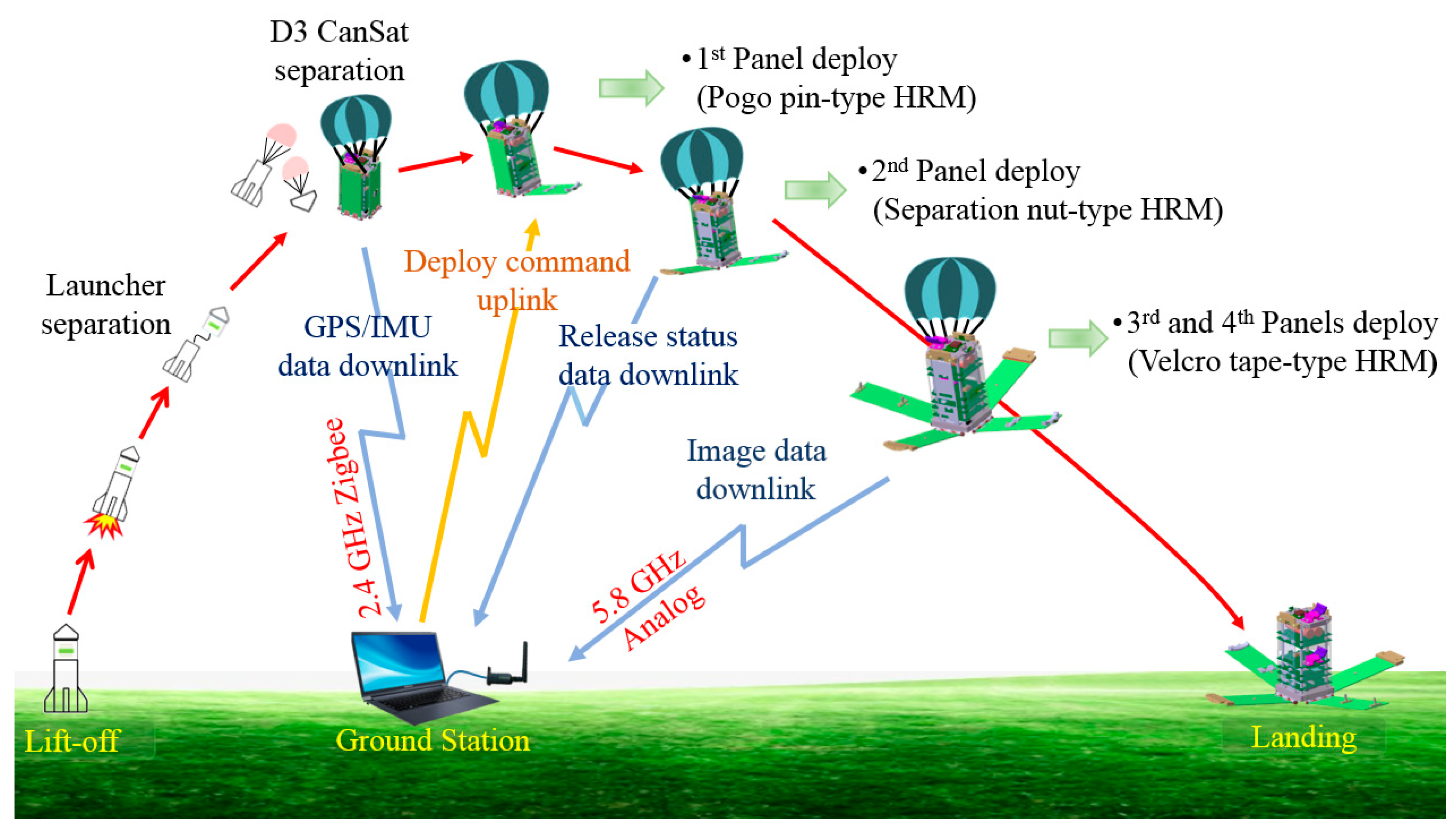
Figure 1 shows the system architecture and operational principle of the DHRM CanSat mission. The system requirements and design configuration of the DHRM CanSat were within the code of conduct of the competition. However, there were no committed mission requirements from the organizer, and thus the experimental verification of the novel burn wire triggering-based HRMs was proposed as the main objective of the DHRM CanSat to overcome the limitations of the conventional HRMs for use in future U-class satellite platforms. The model rocket launcher developed by SaTReC of the Korea Advanced Institute of Science and Technology (KAIST) was used to launch the DHRM CanSat flight model (FM). The CanSat is detached from the launcher bay after reaching the desired altitude of approximately 350 m. Its decent toward the ground is governed by gravity, and the altitude is controlled by a parachute. The drag force from the parachute reaches equilibrium with the gravitational force within a few seconds of the CanSat’s detachment from the launcher, following which the CanSat descends at a constant velocity. The ground station uplink then sends a command to deploy the solar panels, and subsequently, the deployment mechanisms are activated, releasing the solar panels. Table 1 summarizes the basic system specifications of the DHRM CanSat. The dimensions of the DHRM CanSat are 88 × 88 × 184 mm, with a total mass of 0.78 kg (excluding the parachute).
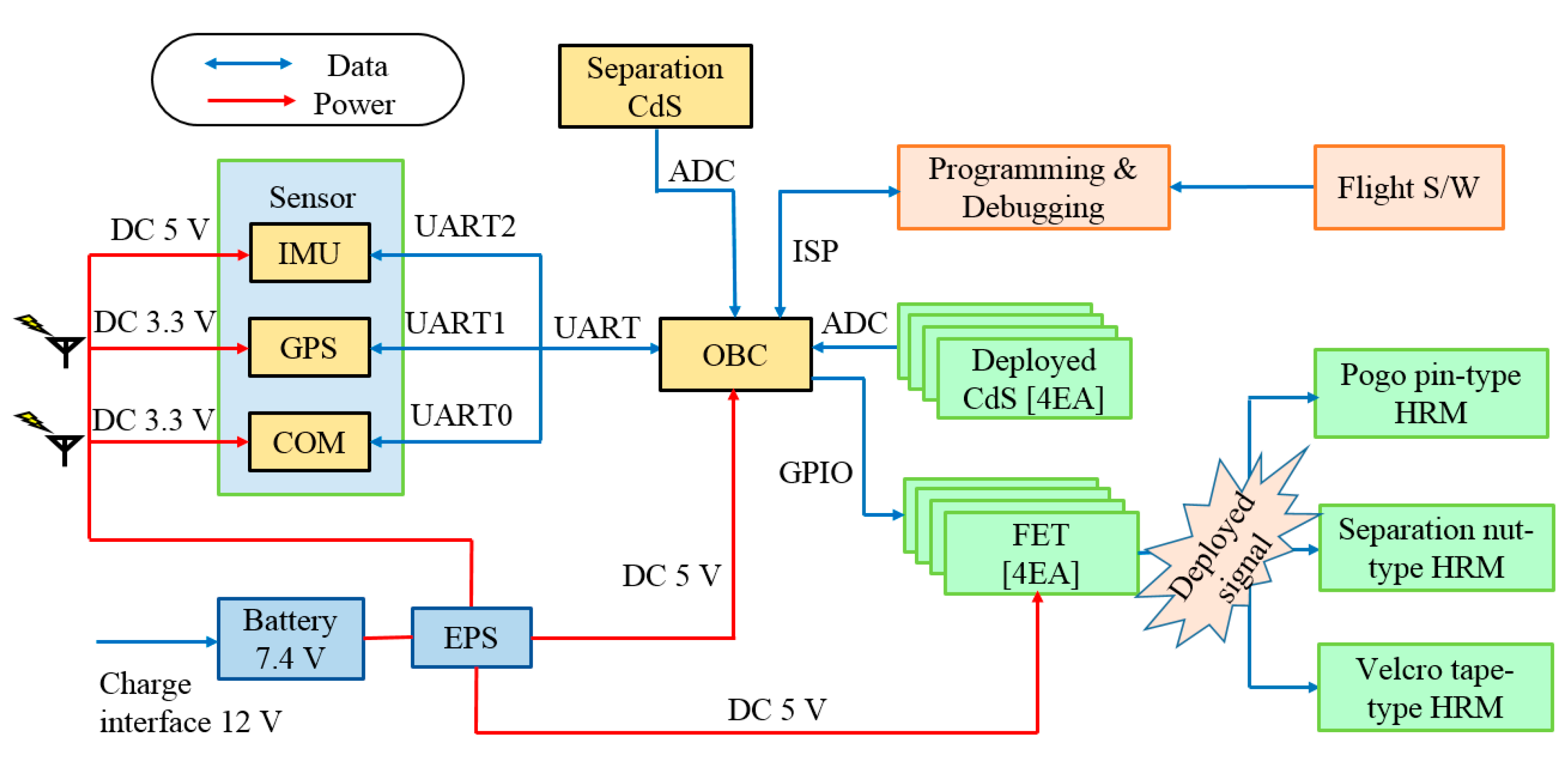
The subsystem of the DHRM CanSat is mainly composed of an onboard computer (OBC), communication system (COMS), sensors, and EPS. The onboard microcontroller unit (MCU: ATmega2560, Microchip Technology Inc., Chandler, AZ, USA) controls the operating systems and gathers the telemetry data from the payloads and sensors, which are subsequently sent to the ground station through the communication network. The CanSat used a communication system (ProBee ZE10, SENA Technologies Inc., San Jose, CA, USA) to communicate with the ground station because of its simplicity and low cost compared to other communication technologies. The telemetry data of the mission and the CanSat health were relayed to the COMS using a universal asynchronous receiver transmitter (UART) internal communication. The sensor module is composed of a global positioning system (GPS: AKBU6, AScen Korea Co., Geumcheon Gu, Seoul, Korea), an inertial measurement unit (IMU: EBIMU-9DOFV3, E2BOX Co., Gyeonggi-do, South Korea), and a cadmium sulfide (CdS) illumination sensor (GL5528, OEM Co., Wan Chai, Hong Kong). The GPS was used to determine the altitude and position data of the CanSat during the launch test. The CdS sensor was used to monitor the separation status and alignment of the CanSat during the flight. Furthermore, the EPS consists of two lithium-ion batteries (LG2N18650-22-R-V3PW, LG Co., Seoul, Korea) and a regulator that provides specific voltages of 3.3 V and 5 V, providing a sufficient power margin to operate the CanSat system at the maximum discharging power in the worst case. Figure 2 illustrates the electrical system block diagram of the CanSat. The red and blue lines in the diagram represent the power distribution and internal communications, respectively.
4. Design Descriptions and Mechanical Configurations of the Proposed HRMs
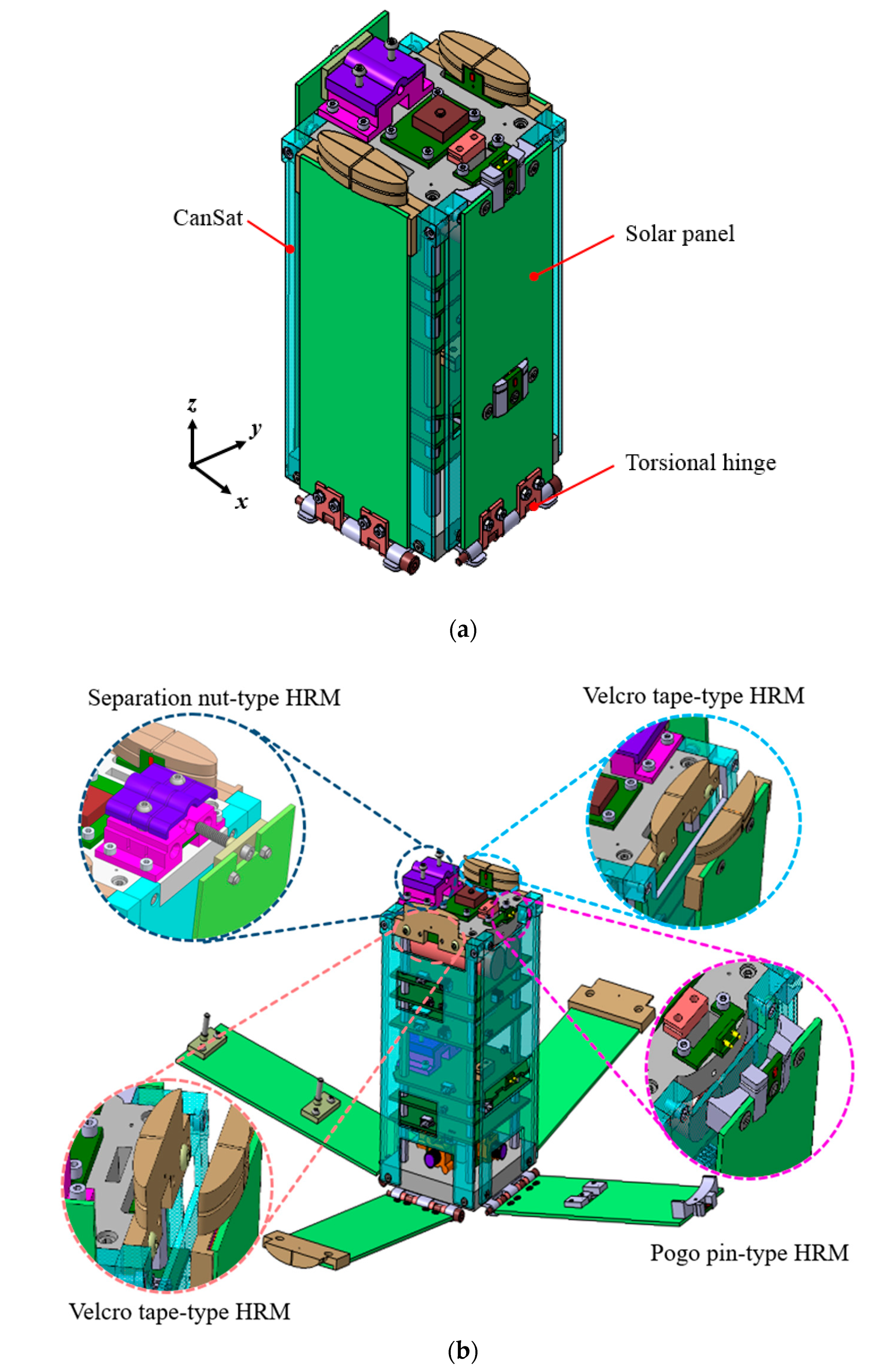
Figure 3a,b show the mechanical configurations of the DHRM CanSat with the deployable solar panels in the stowed and deployed states, respectively. The overall design configuration is within the can-shaped platform, which has four deployable dummy solar panels made of the FR4 material for the implementation of the three types of HRMs. The proposed HRMs were implemented on the +Z rail sides of the DHRM CanSat, and the corresponding sides of the solar panels. At the stowed position of the solar panels, the holding mechanical constraints on the panels were achieved by the Dyneema wire winding along the groove line on the surface of each bracket. The final wire knotting process was performed by tying a surgeon’s knot on the corner points of the brackets for a secure tightening and steady tension on the wire. A surface mount resistor was used as an actuator to release the holding constraints of the solar panels. Once the mechanism is activated, the resistor heats up, and the Dyneema wire tightened along the bracket groove line is thermally cut. The solar panels are then released as a result of the torque on the torsional springs of the hinges. The wire will be secured to the surface of the HRM bracket with Kapton tape (3M™ Polyimide Film Tape 5413, 3M Co., Saint Paul, MN, USA), which will keep the wires in place after the mechanism is activated, preventing the wire from becoming space debris. As per NASA recommendations, a successful deployment mechanism should have four stages: the initial restriction, motion release, deployment guide, and final latching. In this mechanism, the hinging is provided by two torsional hinges. A passive rotating actuator mechanism made of aluminum drives the panel from its stored to the deployed state and latches the panels in place with the end stopper.
We did not manufacture the HRMs based on the CubeSat standard size because this project is dedicated to a CanSat competition. The internal lateral gap for solar cell accommodation on the ISIPOD CubeSat Deployer [18] is 10 mm; hence, the HRMs described in this paper will fit readily inside CubeSat deployers when they are developed to the CubeSat standard. In comparison to the conventional mechanisms, the HRMs were designed to be incorporated on the edge of the solar panel, occupying the minimum surface area on the solar panel and allowing the maximum surface area for solar cell installation. The integration of two HRMs, a pogo pin-type HRM and a separation nut-type HRM, in a single panel here is only to show the application in a larger solar panel, such as 6U or 12U of CubeSat (depends on the system requirements of the satellite and size). The pogo pin-type HRM, separation nut-type HRM, and Velcro tape-type HRM have a total mass of 12.9 g, 35 g, and 33 g, respectively. The mass of bolts utilized to integrate HRMs into the CanSat structure is included in this mass. The design descriptions and distinct advantages of the individual mechanisms are described in the following subsections.
4.1. Pogo Pin-Type HRM
Figure 4a,b show the close-up views of the pogo pin-type HRM implemented on the +X side edge of the DHRM CanSat with a fully stowed and partially deployed solar panel, respectively. The mechanism is mainly composed of the pogo pins, pogo pin printed circuit board (PCB), surface mount resistor, surface mount resistor PCB, brackets, and Dyneema wire. An electromechanical connecting device: pogo pins (MP210-2160-B02 100A, CFE Corporation Co., DongGuan, China) [25], was mechanically soldered on the pogo pin PCB that was constrained on the +ZX side plane edge of the CanSat through bolt fastening. The pogo pin connector consists of a cylindrical barrel, spring, and pin. It has several advantages, such as space-saving connections, relatively low sliding friction, a smaller contact area, and the ability to withstand frictional damage. The main purpose of using the pogo pins hardware in the mechanism is to provide an electromechanical connector for power connecting the edge of the CanSat plane and the resistor PCB during the mechanism activation. The surface mount resistor was mounted on the resistor PCB, which was mechanically constrained by bolts on the solar panel side brackets. The solar panel side bracket (made of aluminum Al-6061) was fastened on the +X side edge of the panel. The pogo pin used in this mechanism has a maximum allowable voltage and current of 12 V and 3 A, respectively. Furthermore, the spring-loaded pin was compressed within the barrel at a certain nominal working stroke. The compressibility of the pogo pin nib ensured a secure physical connection between the two PCBs while maintaining the Dyneema wire and resistor under constant preload tension. The digging effect of the sharp nib during the launch vibration load should be considered because it may affect the physical contact between the two PCBs. Compared to the rigid connecting pin, the spring-loaded pogo pin has a lower digging effect on the electrode pad [22]. Owing to the low friction, the 1 mm working stroke of the pogo pin minimizes the digging effect. Furthermore, the spring-loaded pin’s mechanical operating power of 0.78 N initiates the panel deployment instantly after the thermal cut of the Dyneema wire, thereby interrupting the circuit path quickly and easily. The current measured on the pogo pin determines the deployment status of the solar panel as the electrical circuit opens once the holding constraint on the panel is released.
The holding mechanical constraint was created by tightening a wire of diameter 0.2 mm, made of a Dyneema material, along the guide rail interface notching on the bracket surfaces, i.e., the CanSat structure side bracket and the solar panel side bracket. To tighten the wire, it was wrapped around the brackets and formed into a loop, and the tag end of the wire was passed through it twice. Finally, a surgeon’s knot was tied by drawing the two ends of the wire together at one of the corner fillets of the brackets, which facilitated the application of a steady and tight tension on the knot. Then, the tag end was trimmed close to the knot. The notching on the brackets prevents the wire from misaligning during the launch vibration period. The 0.2 mm diameter Dyneema wire manufactured by Berkley company has a maximum allowable tension of 53.37 N, making it strong enough to stow the solar panel in the launch vibration environment [26]. It has an exceedingly high strength/diameter ratio. The holding constraint can be multiplied by increasing the number of wire windings. Furthermore, the edge fillet on the brackets’ four corners distributes the tightened wire’s frictional shear stress, which helps to secure the structural safety of the tightened wire under a vibration environment.
A surface mount resistor (3216 SMD type, Walsin Technology Co., Taipei, Taiwan) was used as an actuator to release the mechanical constraint of the solar panel [27]. It has an electrical resistance of 4.7 Ω and a maximum power dissipation of 0.25 W at 70 °C. The resistor was soldered to the resistor PCB, which is mechanically constrained by the bolts on the +X side of the dummy solar panel’s rail side. The mechanism is triggered when the OBC receives the deploy command from the ground station. As a result, the power supply of the mechanism is turned on, the resistor heats up, the Dyneema wire tightened around the brackets is cut, and the panel is deployed by the torsional force of the hinges. Furthermore, the elongated structural interface at the two ends of the bracket restricts the in-plane mechanical movement of the panel within a range of 1 mm of the working stroke of the pogo pins. The application of the in-plane mechanical restraint in the mechanism prevents unintentional mechanical panel strikes on the pogo pin hardware under a vibration environment. The same mechanism was implemented in the solar panel’s center to multiply the holding constraints. The hardware specifications used in this mechanism are listed in Table 2.
4.2. Separation Nut-Type HRM
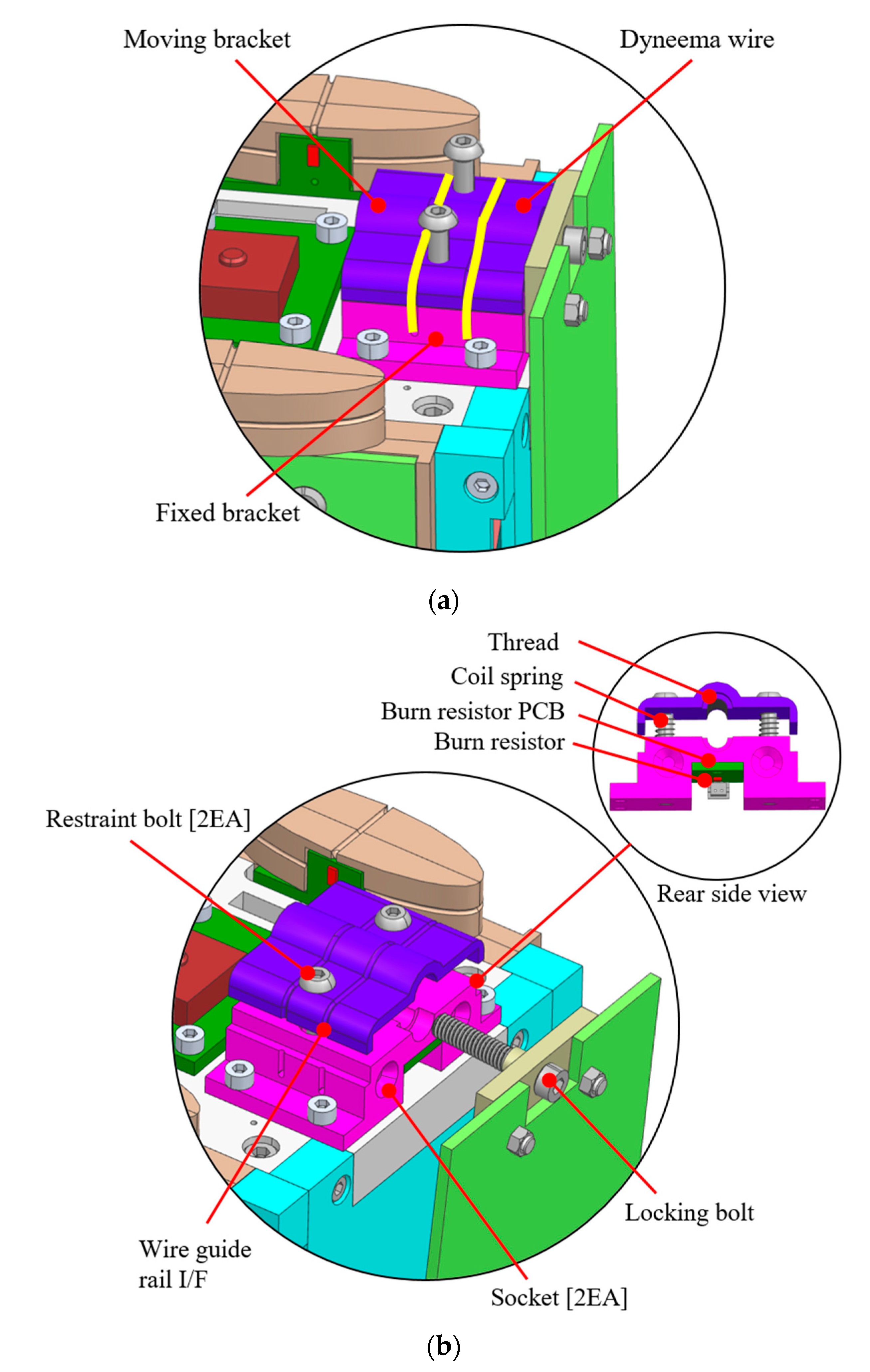
Figure 5a,b show the close-up views of the separation nut-type HRM on the DHRM CanSat with the solar panel in the fully stowed and partially deployed states, respectively. The mechanism mainly consists of fixed and moving brackets, a locking bolt, restraint bolts, a surface mount resistor, a resistor PCB, and Dyneema wire. The use of two plane brackets, i.e., the fixed and moving brackets, made of aluminum as the nuts for the holding constraint of the system, distinguishes this mechanism from the conventional wire cutting release mechanisms. The fixed bracket is mechanically attached to the upper edge of the ‒X side of the DHRM CanSat. The moving bracket is integrated into the overhead of the fixed bracket. A mechanical nut for the locking bolt is formed by tightening the Dyneema wire along the groove guidelines on the fixed and moving bracket surfaces. The locking bolt is mechanically fastened on the rail side of the −X side solar panel through the two bolts. The moving bracket’s U-shaped notch and the locking bolt have threads on the surface. The wire tightening around the brackets, together with the combination of the fixed bracket, moving bracket, and locking bolt, creates an out-of-plane mechanical constraint on the solar panel, as shown in Figure 5a. A ball-shaped overhead tip of the screw bolts used to fasten the locking bolt on the solar panel acted as a ball, and a round notching was made on the surface of the fixed bracket for the socket. This mechanism has an in-plane constraint owing to the application of the ball and socket joints. The socket prevents the Dyneema wire from unintentional loosening in the vibration environment by restricting the movement of the ball in a specific nominal gap.
The surface mount resistor was used as an actuator to release the mechanical constraint between the nut of the bracket and the locking bolt of the solar panel. The resistor was soldered to the resistor PCB, which is mechanically attached to the rear surface of the fixed bracket. Thus, the proposed mechanism is considerably improved to ensure the mechanical safety of the system, as the heating elements are not recommended for use on the front surface of the satellite as they are prone to malfunction in the sunny period of the orbit. The Dyneema wire wound along the guide rail interface on the bracket surfaces is cut during the activation of the resistor, releasing the mechanism’s holding constraint by an upward displacement of the moving bracket enabled by the restoration force of the coil springs integrated on the restraint bolts. The rounded head of the restraint bolts vertically mounted on the fixed bracket restricts the upward movement of the moving bracket beyond a certain height, as shown in Figure 5b. The separation nut-type HRM has a higher holding constraint in the stowed configuration of the panel than the other wire cutting mechanisms due to the mechanical thread present around the U-shaped notch of the moving bracket and locking bolt. The same mechanism is implemented in the center of the −X side solar panel of the CanSat, which increases the system’s holding strength and reduces the panel’s dynamic displacement under vibration environments.
4.3. Velcro Tape-Type HRM
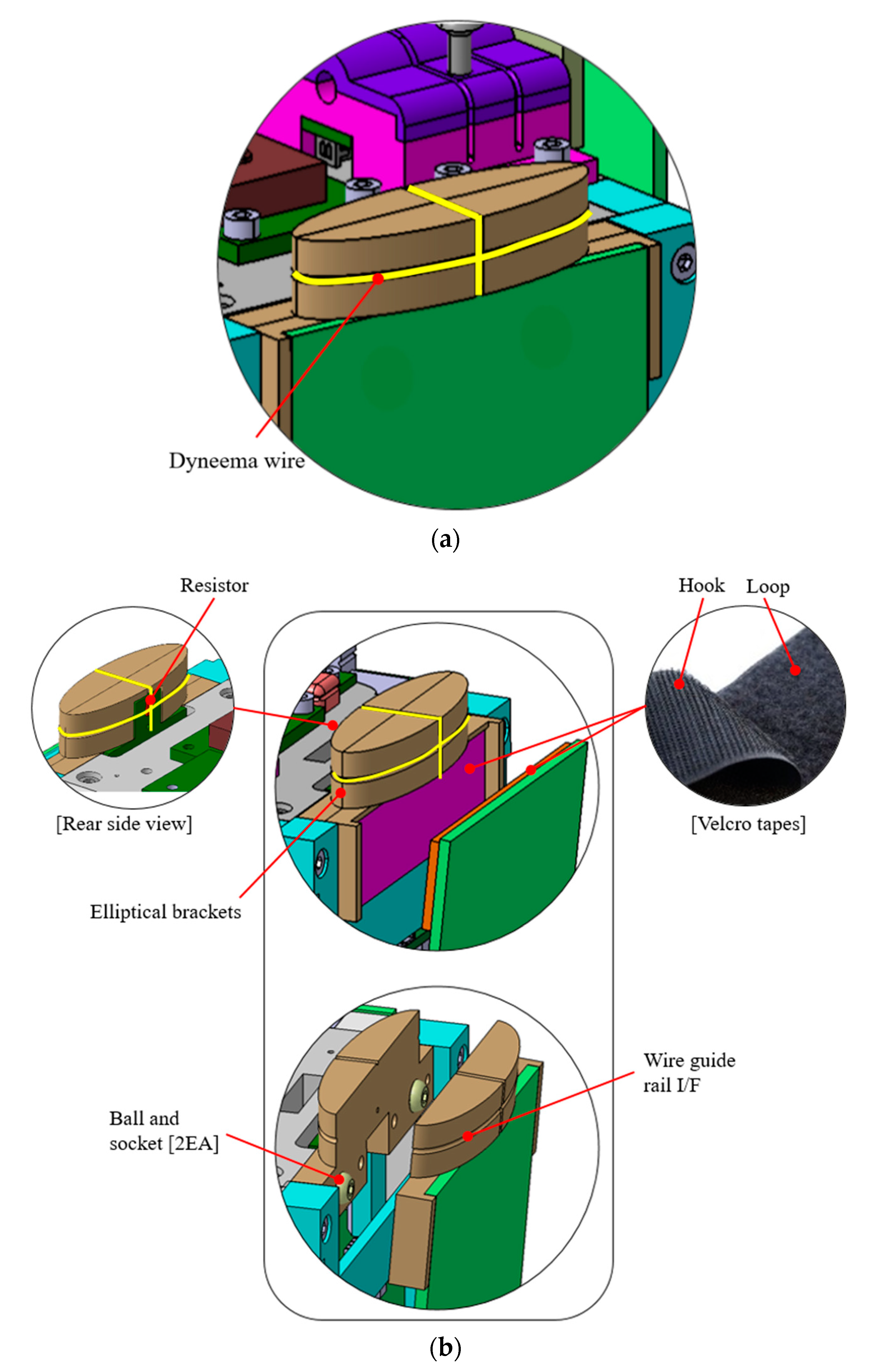
Figure 6a,b show the close-up views of the Velcro tape-type HRM integrated on the +Y and −Y sides of the DHRM CanSat solar panels. The mechanism is composed of elliptical-shaped brackets, Velcro tapes, a surface mount resistor, a resistor PCB, and Dyneema wire. Two elliptical-shaped brackets, i.e., the CubeSat structure side bracket and the solar panel side bracket (made of aluminum Al-6061), are used as an HRM housing for the Velcro tape-type HRM. The brackets are mechanically fastened through bolts on the +Y and −Y sides of the DHRM CanSat, as well as the rails of the corresponding sides of the solar panel, as shown in Figure 6a. The housing brackets support the HRM components mechanically and serve as a wire tightening guideline for systematic wire knotting. The purpose of designing the brackets as elliptical was to reduce the mass of the HRM and also lower the stress on the tightened wire at the brackets’ corners, which would be comparatively higher if the brackets were rectangular. The basic operating principle of the Velcro tape-type HRM is based on a burn wire triggering release mechanism. However, the main features of this mechanism that distinguish it from the conventional mechanisms are the use of the Velcro tape for easy access to the test port on the satellite without releasing the Dyneema wire, and reducing the dynamic stress on the holding knot of the HRM under a vibration environment facilitated by the vibration damping characteristic of the Velcro tape. The Velcro tape is a type of hook and loop fastener composed of two lineal fabric strips that are attached to two opposing surfaces to be fastened. The Velcro tape was mounted on the +Z upper edge of the +Y and −Y sides of the solar panels, as well as the base of the corresponding side elliptical brackets, using double-sided 3MTM 966 adhesive transfer tape [28], manufactured by 3M Company. The 3MTM 966 adhesive transfer tape is a double-sided high-temperature acrylic adhesive with low outgassing properties that meet NASA’s low volatility and outgassing specifications. As a result, it has been used for bonding purposes in aerospace applications [29,30]. Table 3 lists the specifications of the adhesive tape.
A single wire piece is used for holding the mechanical constraint in the separation nut-type HRM and Velcro tape-type HRM, even though two wire guide rail interfaces were constructed on the HRM brackets. On the rear side of the burn resistor, a crisscrossing of wire was constructed that allows the wire to burn up by a single resistor when the mechanism is activated. The wire tightening in the conventional burn wire triggering release mechanism was performed on the flat surface of a solar panel by simply creating hole interfaces, which make it difficult to apply a steady tension on the final knot of the wire. However, in the proposed HRM, the wire tightening process is much simpler and reliable because of the cross-pattern winding of the wire, and the final knotting is performed in the corner of the elliptical bracket via the surgeon’s knot.
The activation of the resistor soldered on the resistor PCB initiates the release of the holding constraint. The resistor PCB was mechanically mounted on the back surface of the CanSat side elliptical bracket. When the mechanism was activated, the resistor heated up and thermally cut the Dyneema wire tightened around the elliptical brackets, releasing the solar panel, the elliptical bracket on the solar panel side, and the Velcro tape. Furthermore, the Velcro tape in the mechanism makes it simple to attach and detach the solar panel without cutting the Dyneema wire. This feature allows for easy access to other subsystem integration, and testing on the edge of the CanSat. This stress-free access to the structure is expected to be extremely beneficial during the pre-launch test as most of the subsystems are installed on the external sides of the satellites. The electrostatic discharge (ESD) event during the solar panel detachment would be modest due to the small size of the Velcro tape and the gradual detachment. The generated charges are drained to the ground through the body. Furthermore, the use of Velcro tape in the HRM reduces the vibrational stress on the panel during the severe launch vibration period owing to its vibration damping properties. Malavart et al. [31] performed an outgassing test of the hook and loop to the ECSS-QST-70-02C standard. Additionally, the hook and loop tensile and shear static load capacities were measured on a Surrey Satellite Technology Ltd. (SSTL, Guildford, UK) tensile test machine at ambient, hot (+70 °C) and cold (−40 °C) temperatures.
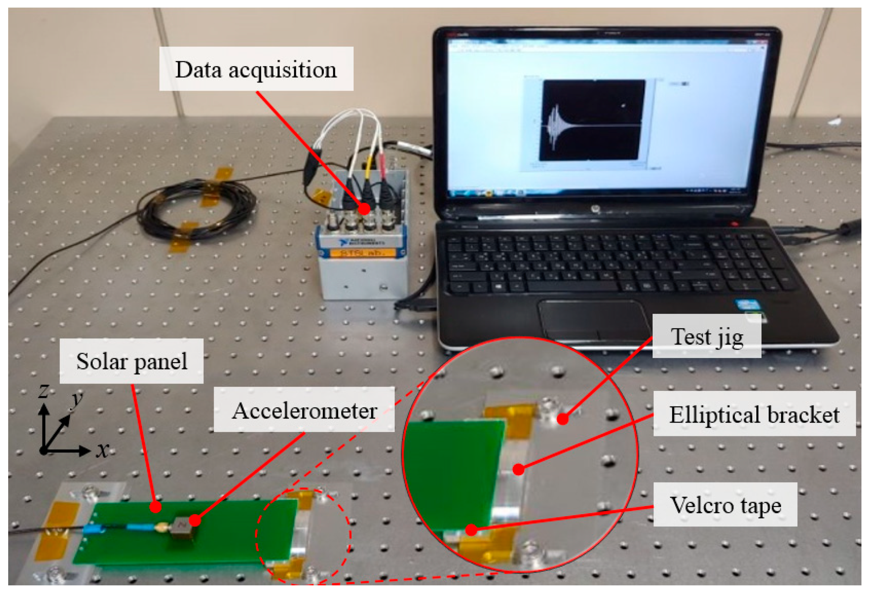
To confirm the effectiveness of the Velcro tape on the HRM for vibration damping, solar panel free vibration tests were conducted at ambient room temperature (25 °C), with the interfaces of the hinge holes rigidly clamped, and the use of the Velcro tape-type HRM on the other edge of the solar panel. Figure 7 shows the free vibration test setup configuration of the solar panel employing the Velcro tape-type HRM. The Velcro tape fastener was mechanically attached to the HRM bracket base surface and the +X side solar panel’s edge using 3MTM 966 adhesive transfer tape. The roving hammer method was used to excite the solar panel in its free vibration. An accelerometer sensor was mounted at the solar panel center to obtain the time domain frequency responses. To compare the results, a free vibration test of the solar panel without using the Velcro tape in the HRM was also carried out.
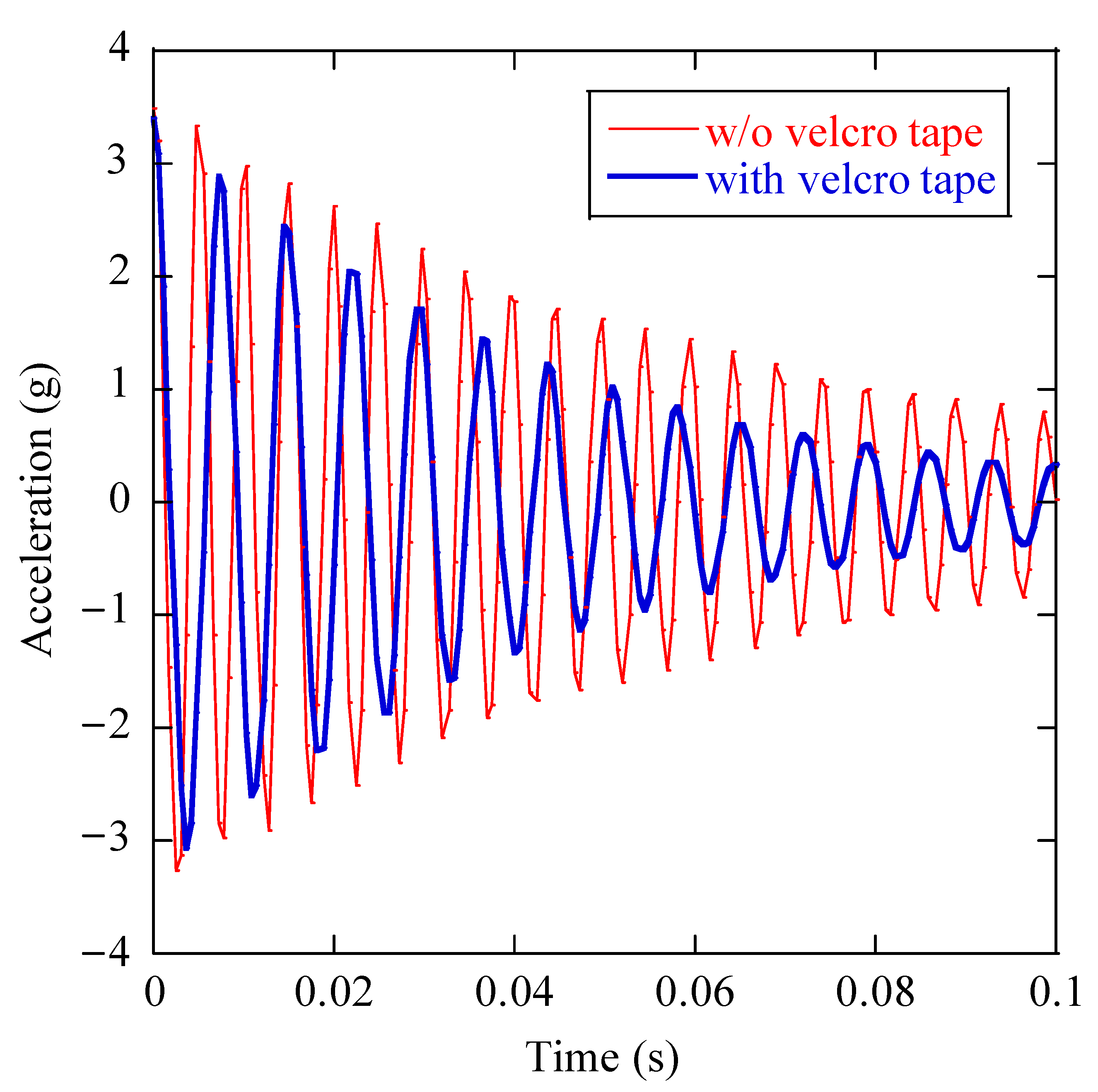
Figure 8 shows the time histories of the free vibration responses of the solar panel. The results show that the vibration of the solar panel can be effectively suppressed by employing the Velcro tape on its mounting interface. The first eigenfrequencies of the solar panel module with and without the Velcro tape are 137.74 Hz and 206.18 Hz, respectively. The damping ratio calculated from the vibration period of the solar panel with the Velcro tape is 0.16, which is higher by a factor of 1.5 than that of the solar panel without using the Velcro tape. The ability of the Velcro tape to rapidly attenuate the transmitting vibration on the solar panel was verified by the free vibration tests. The application of the Velcro tape-type HRM in a deployable solar panel could ensure the structural safety of the installed solar cells by reducing the dynamic stress on the solar panels.
According to SpaceX’s Falcon launch vehicle user’s guide, the maximum payload temperature exposed during the flight will be in the range of 49 to 85 °C [32]. The tape’s maximum permitted temperature is far greater than the temperature of the fairing during launch; thus, the bonding of the adhesive tape and hook and loops would not be a problem. Furthermore, Bhattarai et al. [33] conducted launch vibration tests on a PCB-based deployable solar panel, where thin PCB stiffeners with a thickness of 0.5 mm were attached to the back surface of the PCB panel with double-sided 3MTM 966 acrylic tapes. The visual inspection of the solar panel performed after the tests did not report any crack, dissociation, and plastic deformation on the stiffeners and adhesive bonding.
5. DHRM CanSat Ground Station
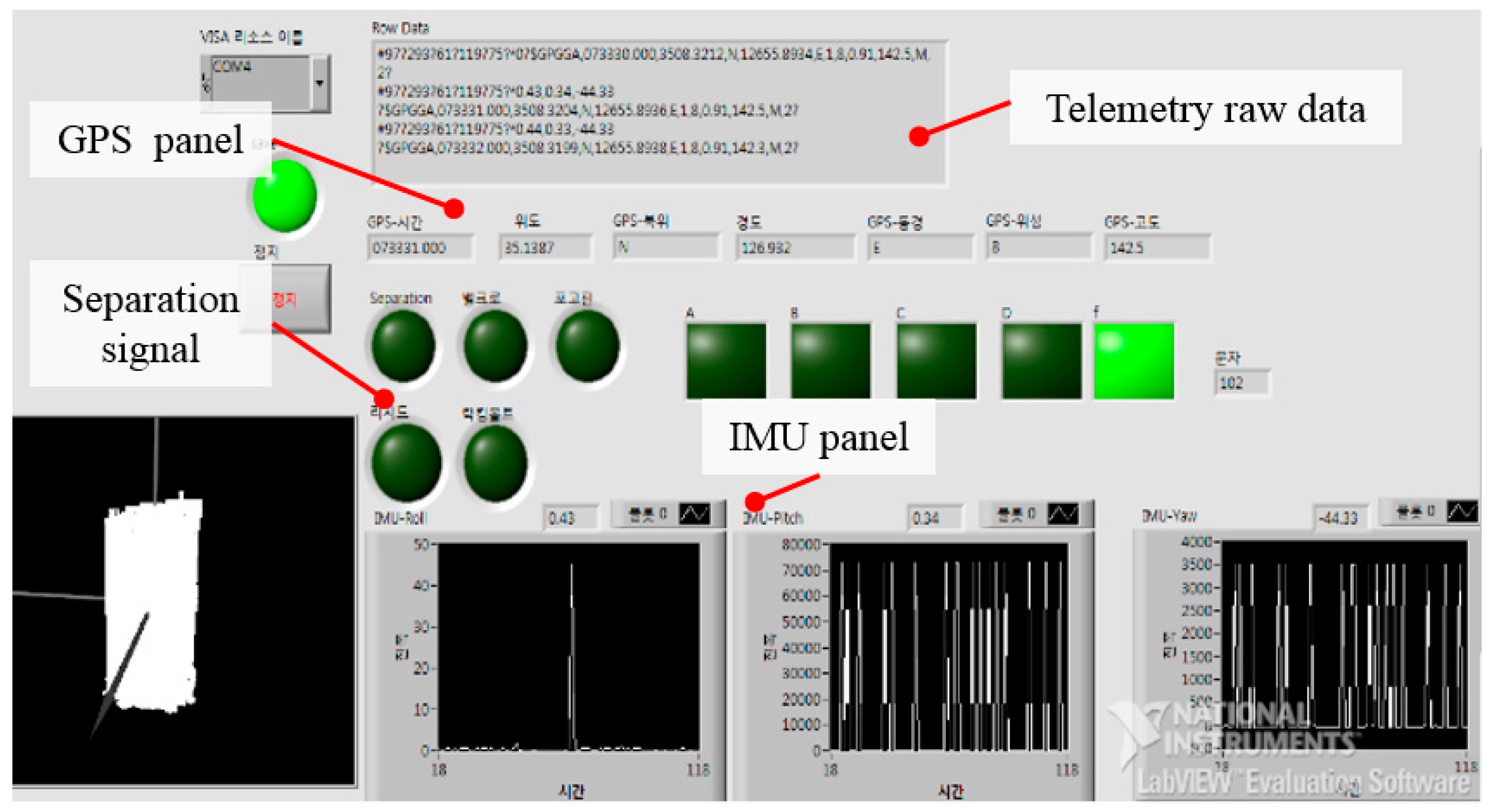
Figure 9 shows a screenshot of the software developed for the DHRM CanSat ground station. The ground station comprised a payload control panel for sending commands to the OBC that relayed the deployment signal to the HRMs. The ground station used a universal serial bus (USB) module (ProBee-ZU10, SENA Co., Irvin, CA, USA) for communicating with the CanSat because of its cost-effectiveness, low power consumption, and robust data transfer capability of 250 kbps within a distance of 1.6 km. The CanSat’s altitude and position data were collected using the IMU and GPS panels. Furthermore, the solar panel separation signal, raw telemetry data, and real-time graphical visualization panels were used to verify the functionality of the mechanisms and the DHRM CanSat mission success.
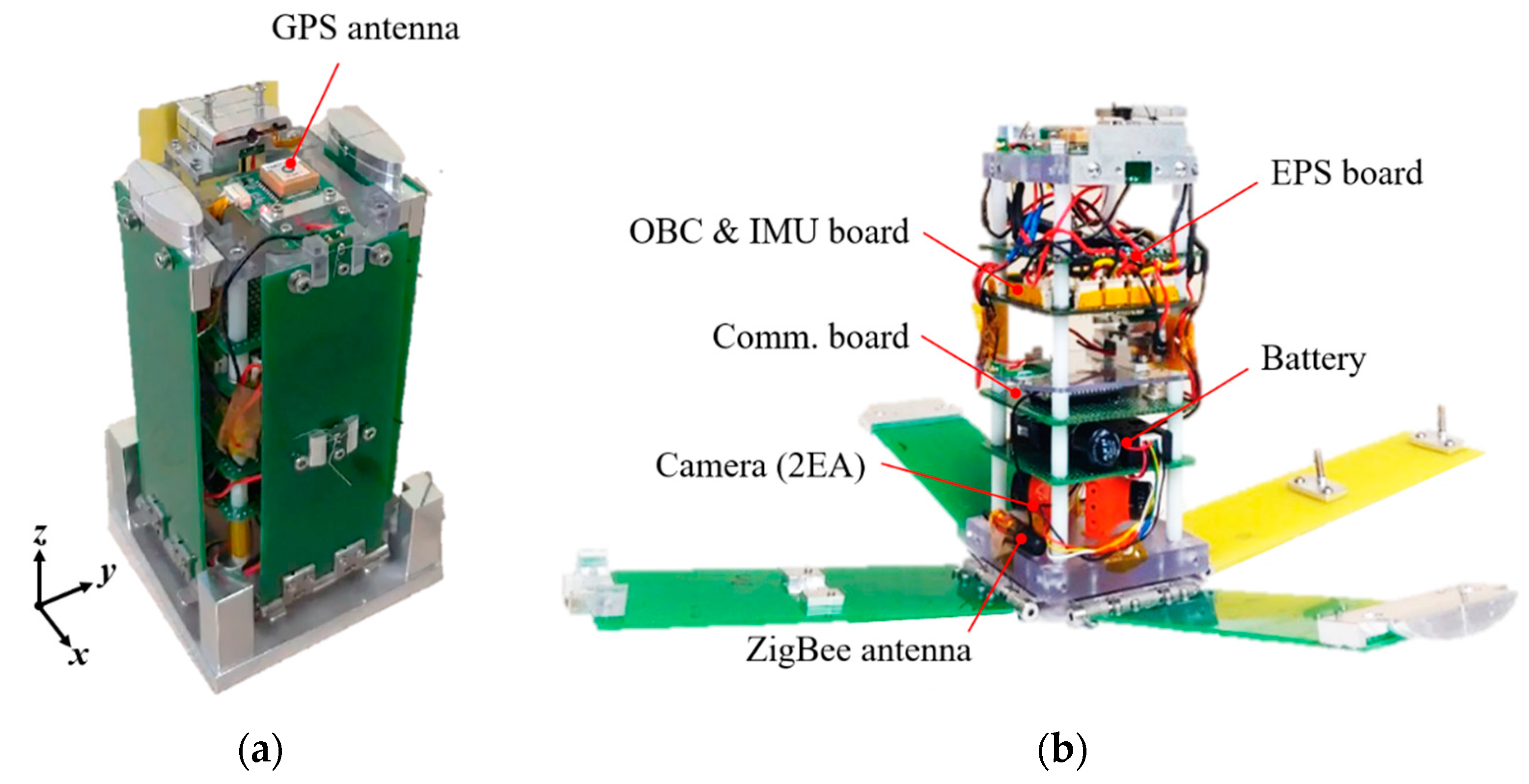
6. On-Ground Validation Tests before the Launch
Figure 10 illustrates the payloads and subsystem accommodations in the DHRM CanSat flight model. Several pre-launch on-ground functional tests were conducted from the subsystem to the system level to comply with the contest’s system requirements and validate the effectiveness of the mechanisms. The effectiveness of the proposed HRMs was demonstrated through the payload-level tests. Two real-time cameras were installed on diagonally opposite sides of the CanSat to verify the deployment status of the solar panels during the launch experiment test. As a result, the solar panel deployment can be monitored and verified in real time from the ground station. To validate the communication system implemented in the CanSat, system-level long-range communication tests were performed. However, the subsystem and mechanism qualification-level dynamic tests, such as vibration and shock, and thermal cycling tests were not performed since the project is dedicated to the CanSat competition.
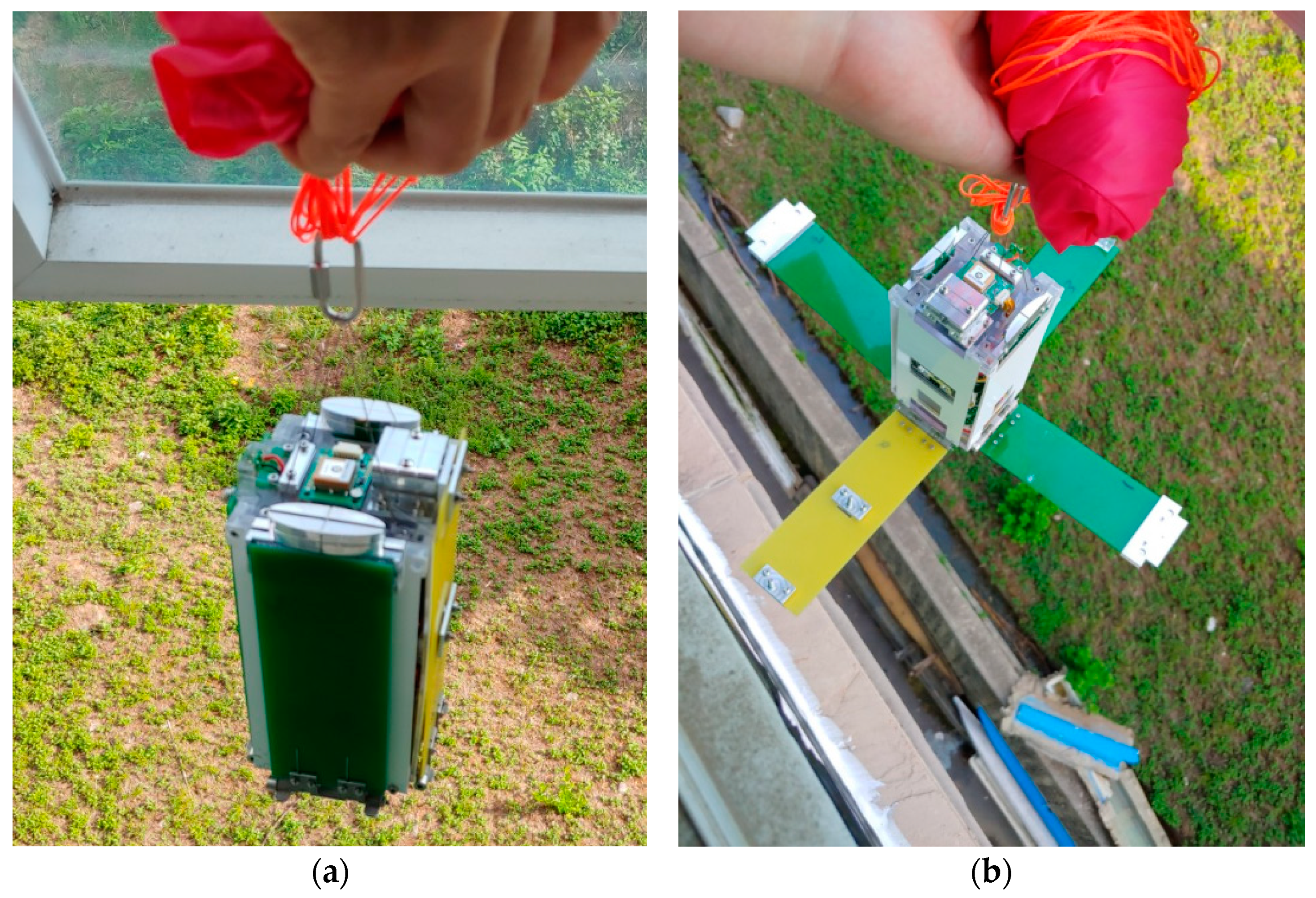
Figure 11a,b show the release function test setup of the proposed HRMs in the flight model of the CanSat before and after deployment of the solar panels, respectively. The tests were performed at ambient room temperature. The mechanisms were activated when the OBC received a deployment command signal from the ground station, and all the solar panels were successfully deployed as intended, as shown in Figure 11b.
Figure 12 shows the images captured by the onboard cameras of the CanSat in real time for the solar panel deployment status. The input voltage, separation signal, and acceleration response of each solar panel monitored during the on-ground release function tests of the mechanisms are shown in Figure 13. The results of the solar panel separation status and acceleration response during deployment indicate that all the panels were deployed within 0.89 s from the initiation of the burn wire triggering in the mechanism. The functional performance of the mechanisms at the system and subsystem levels was verified through these pre-launch on-ground tests.
7. Launch Experiment Results
After the on-ground test validation, the actual flight test of the DHRM CanSat was performed as the payload of a model rocket launched at the Goheung Space Center, South Korea. The CanSat was successfully separated from the model rocket after reaching the designated altitude without any anomalies. Figure 14 shows the flight status data obtained from the GPS, IMU, and OBC during the DHRM CanSat flight. The flight status data were successfully obtained, and the GPS launch status data show that the CanSat was at its peak altitude at the time of 14:23. Furthermore, the CanSat was separated from the rocket cargo bay at an altitude of approximately 350 m above the Earth’s surface. The altitude of the CanSat was controlled by a parachute during its descent to the ground. The deployment of all the solar panels was successfully conducted during the descent of the CanSat via telecommands from the ground station. The ground station received the solar panels’ separation signal, raw telemetry data, and real-time images from the onboard camera, which verified the holding and release function of the mechanisms proposed in this study.
The flight test results verify the functional performance of the proposed burn wire triggering-based HRMs while satisfying the criteria of the DHRM CanSat mission objectives. The DHRM CanSat was a grand prize award winner at the seventh CanSat contest of the Republic of Korea. To assess their effectiveness in actual space missions, a future study will validate the mechanisms’ structural safety in a vibration environment as well as their functionality in an in-orbit environment through qualification-level launch and in-orbit environmental tests.
8. Conclusions
In this study, the design effectiveness and functional performance of the proposed optimized versions of burn wire triggering-based HRMs were experimentally demonstrated through the DHRM CanSat mission. The mission of the DHRM CanSat was to demonstrate the technology of the newly proposed HRMs for application in the deployable appendages of nanosatellites. These mechanisms have many advantages, including an increased loading capability, multi-plane constraints, a reliable release action, and ease of use, which help overcome the limitations of the conventional burn wire triggering release mechanisms. The demonstration model of the HRMs was fabricated and tested by implementing the deployable dummy solar panels on the DHRM CanSat. To comply with the system requirements of the CanSat, the mechanisms’ functional performance was tested on the ground at the system and subsystem levels before the actual flight experiment. All the panels were deployed successfully in the flight test within a second of resistor triggering in the mechanism. The ground station received raw telemetry data of the CanSat’s health and the solar panel’s deployment status signals, which validated the mission objective of the DHRM CanSat. In addition, onboard camera images verified the deployment status of the solar panels in real time. These results validate the design feasibility and functionality of the proposed mechanisms for application in the deployable appendages of nano-class satellites. A future study will validate the structural safety of the mechanisms in launch vibration environments, as well as their reliable release functionality in an in-orbit environment at the qualification level.
Author Contributions
Conceptualization, S.B., J.-S.G., and H.-U.O.; methodology, S.B., J.-S.G., and H.-U.O.; software, S.B. and J.-S.G.; formal analysis, S.B. and J.-S.G.; validation, S.B., J.-S.G., and H.-U.O.; writing—original draft preparation, S.B.; writing—review and editing, H.-U.O.; supervision, H.-U.O.; funding acquisition, H.-U.O. All authors have read and agreed to the published version of the manuscript.
Funding
This research was funded by the Ministry of Science and ICT (MSIT).
Institutional Review Board Statement
Not applicable.
Informed Consent Statement
Not applicable.
Data Availability Statement
The data used to support the findings of this study are available from the corresponding author upon request.
Acknowledgments
This research was supported by the Satellite Technology Research Center (SaTReC) and funded by the Ministry of Science and ICT (MSIT).
Conflicts of Interest
The authors declare that there is no conflict of interest regarding the publication of this paper.
References
- Sako, N.; Tsuda, Y.; Ota, S.; Eishima, T.; Yamamoto, T.; Ikeda, I.; Li, H.; Yamamoto, H.; Tanaka, H.; Tanaka, A.; et al. Cansat suborbital launch experiment-university educational space program using can sized pico-satellite. Acta Astronaut. 2001, 48, 767–776. [Google Scholar] [CrossRef]
- Kizilkaya, M.O.; Oguz, A.E.; Soyer, S. CanSat Descent Control System Design and Implementation. In Proceedings of the 8th International Conference on Recent Advances in Space Technologies (RAST), Istanbul, Turkey, 19–22 June 2017; pp. 241–245. [Google Scholar]
- Colin, A.; Lizarraga, M.J. The CanSat technology for climate monitoring in small regions at altitudes below 1 km. In Proceedings of the IAA Climate Change and Disaster Management Conference, Mexico City, Mexico, 17 September 2015; pp. 1–10. [Google Scholar]
- Colin, A. A pico-satellite assembled and tested during the 6th CanSat leader training program. J. Appl. Res. Technol. 2017, 15, 83–91. [Google Scholar] [CrossRef] [Green Version]
- Oh, H.U.; Kim, H.I.; Kim, J.K.; Choi, J.S.; Kim, S.H. Smartphone CanSat for actualization of real-time streaming video calls using remote screen touch system with shape memory alloy actuator. Trans. Jpn. Soc. Aeronaut. Space Sci. 2019, 62, 256–264. [Google Scholar] [CrossRef]
- Chae, B.G.; Oh, H.U. Development of Power Plant Trio CanSat Platform Powered by Solar, Wind and Piezo Energy Harvesting Systems. Int. J. Aeronaut. Space Sci. 2021. [Google Scholar] [CrossRef]
- Gontier, J.; Carlos, H.G.; Joel, B.G.; Christine, E. CANSAT: Multiphysical experimental design of a probe come back mission. In Proceedings of the 64th IAC-International Astronautical Congress, Beijing, China, 23–27 September 2013; pp. 1–9. [Google Scholar]
- Sakamoto, H.; Miura, T.; Kawaguchi, K.; Kamiya, T.; Akagi, H.; Akiyama, K.; Okada, Y.; Shirasaka, S.; Kohtake, N. Systems engineering education through students’ CanSat project interacting with young professional engineers. Trans. Jpn. Soc. Aeronaut. Space Sci. Aerosp. Technol. Jpn. 2014, 12, 11–17. [Google Scholar] [CrossRef] [Green Version]
- Chosun University, Space Technology Synthesis Laboratory. Available online: https://www.stslab.chosun.ac.kr/ (accessed on 28 March 2021).
- CanSat Project, Chosun University, Space Technology Synthesis Laboratory. Available online: https://www.stslab.chosun.ac.kr/DHRM-cansat-2018 (accessed on 28 March 2021).
- Lee, S.; Hutputanasin, A.; Toorian, A.; Lan, W.; Munakata, R. CubeSat Design Specification Rev. 12; California Polytechnic State University: San Luis Obispo, CA, USA, 2009; pp. 1–22. Available online: https://srl.utu.fi/AuxDOC/tke/radmon/cubesat_standard.pdf (accessed on 28 March 2021).
- Woo, S.H.; Han, J.H. Mid frequency shock response determination by using energy flow method and time domain correction. Shock. Vib. 2013, 20, 847–862. [Google Scholar] [CrossRef]
- Oh, H.U.; Jo, M.S.; Lee, K.M.; Kim, D.J. Spaceborne tilt mirror mechanism and application of shape memory alloy actuator to implement fail-safe function in emergency mode. Trans. Jpn. Soc. Aeronaut. Space Sci. 2012, 55, 373–378. [Google Scholar] [CrossRef] [Green Version]
- National Aeronautics Space Administration (NASA). Launch Services Program, Program Level Dispenser and CubeSat Requirements Document; John F. Kennedy Space Center: Merritt Island, FL, USA, 2014; pp. 1–14. Available online: https://www.nasa.gov/pdf/627972main_LSP-REQ-317_01A.pdf (accessed on 28 March 2021).
- Thurn, A.; Huynh, S.; Koss, S.; Oppenheimer, P.; Butcher, S.; Schlater, J.; Hagan, P. A nichrome burn wire release mechanism for CubeSats. In Proceedings of the 41st Aerospace Mechanisms Symposium, Pasadena, CA, USA, 16–18 May 2012; pp. 479–488. [Google Scholar]
- Gardiner, J. Suitability of Nickel Chromium Wire Cutters as Deployable Release Mechanisms on CubeSats in Low Earth Orbit. Physics Capstone Project, Paper 24. Available online: https://digitalcommons.usu.edu/phys_capstoneproject/24 (accessed on 28 March 2021).
- Bharadwaj, B.K.; Gupta, Y.V. Design analysis and testing of antenna development mechanism for CubeSat applications. In Proceedings of the 2nd International Space Conference, New Delhi, India, 8–9 January 2015; pp. 1–5. [Google Scholar]
- ISISPACE-Innovative Solutions in Space, ISIPOD CubeSat Deployer. Available online: https://www.isispace.nl/product/isipod-cubesat-deployer/ (accessed on 28 March 2021).
- Blackwell, W.J.; Allen, G.; Galbraith, C.; Leslie, R.; Osaretin, I.; Scarito, M.; Shields, M.; Thompson, E.; Toher, D.; Townzen, D.; et al. MicroMAS: A first step towards a nanosatellite constellation for global storm observation. In Proceedings of the 27th Annual American Institute of Aeronautics and Astronautics (AIAA)/Utah State University (USU) Conference on Small Satellites, Logan, UT, USA, 10–15 August 2013; pp. 1–10. [Google Scholar]
- Cho, D.H.; Choi, W.S.; Kim, M.K.; Kim, J.H.; Sim, E.; Kim, H.D. High-resolution image and video CubeSat (HiREV): Development of space technology test platform using a low-cost CubeSat platform. Int. J. Aerosp. Eng. 2019, 2019, 1–18. [Google Scholar] [CrossRef]
- Kailaje, A.P.; Brindavan, M.; Tapadia, P.; Paliya, A.; Ganti, H.; Thakurta, V.; Kumar, A.A. Implementation of wire burn deployment mechanism using COTS resistors and related investigations. In Proceedings of the 2019 IEEE Aerospace Conference, Big Sky, MT, USA, 2–9 March 2019; pp. 1–19. [Google Scholar]
- Bhattarai, S.; Kim, H.; Jung, S.H.; Oh, H.U. Development of pogo pin based holding and release mechanism for deployable solar panel of CubeSat. Int. J. Aerosp. Eng. 2019, 2019, 1–13. [Google Scholar] [CrossRef]
- Innovative Solutions in Space B.V., Custom Solar Panels-ISIS-Innovative Solutions in Space. Available online: https://www.isispace.nl/product/custom-solar-panels-cubesats-nanosats (accessed on 30 June 2021).
- GOMspace, NanoPower DSP-GOMspace, Deployable Solar Panels for 3U and 6U Satellites. Available online: https://gomspace.com/shop/subsystems/power/nanopowerdsp.aspx (accessed on 30 June 2021).
- CFE Company, Spring-Loaded Connectors. Available online: https://www.cfeconn.com/2-54mm-pitch-through-hole-pogo-pin-catalog.html (accessed on 30 June 2021).
- Berkley NanoFil Uni-Filament Fishing Wire. Available online: https://www.berkley-fishing.com/collections/uni-filament-line/products/nanofil-1285551 (accessed on 20 June 2021).
- PSA Company, Resistors-Walsin Technology, Resistors 3216 SMD. Available online: http://www.passivecomponent.com/products/resistors/ (accessed on 28 March 2021).
- 3M Company, 3MTM Adhesive Transfer Tape 966-Technical Data Sheet. Available online: https://3m.citrination.com/pif/000314?locale=en-US (accessed on 28 March 2021).
- Seefeldt, P.; Spietz, P.; Sproewitz, T.; Grundmann, J.T.; Hillebrandt, M.; Hobbie, C.; Ruffer, M.; Straubel, M.; Tóth, N.; Zander, M. Gossamer-1: Mission concept and technology for a controlled deployment of gossamer spacecraft. Adv. Space Res. 2017, 59, 434–456. [Google Scholar] [CrossRef] [Green Version]
- Park, T.Y.; Shin, S.J.; Park, S.W.; Kang, S.J.; Oh, H.U. High-damping PCB implemented by multi-layered viscoelastic acrylic tapes for use of wedge lock applications. Eng. Fract. Mech. 2021, 241, 1–13. [Google Scholar] [CrossRef]
- Malavart, A.; Ferris, M.; Philips, N. Novel hold down and release mechanism using hook and loop technology for small deployable arrays. In Proceedings of the European Space Mechanisms and Tribology Symposium, University of Hertfordshire, Hatfield, UK, 20–22 September 2017; pp. 1–7. [Google Scholar]
- SpaceX Falcon User’s Guide. Available online: https://www.spacex.com/media/falcon_users_guide_042020.pdf (accessed on 30 June 2021).
- Bhattarai, S.; Kim, H.; Oh, H.U. CubeSat’s deployable solar panel with viscoelastic multilayered stiffener for launch vibration attenuation. Int. J. Aerosp. Eng. 2020, 2020, 1–10. [Google Scholar] [CrossRef]
Figure 1.
System architecture and operation concept for the DHRM CanSat mission.

Figure 2.
Block diagram of the electrical system of the DHRM CanSat.

Figure 3.
Mechanical configurations of the DHRM CanSat illustrating the solar panels in the (a) stowed and (b) deployed states.
Figure 3.
Mechanical configurations of the DHRM CanSat illustrating the solar panels in the (a) stowed and (b) deployed states.

Figure 4.
Close-up views of the pogo pin-type HRM: (a) fully stowed solar panel, and (b) partially deployed solar panel.
Figure 4.
Close-up views of the pogo pin-type HRM: (a) fully stowed solar panel, and (b) partially deployed solar panel.

Figure 5.
Close-up views of the separation nut-type HRM for the (a) fully stowed and (b) partially deployed solar panels.
Figure 5.
Close-up views of the separation nut-type HRM for the (a) fully stowed and (b) partially deployed solar panels.

Figure 6.
Close-up views of the Velcro tape-type HRM showing the (a) fully stowed and (b) partially deployed solar panels.
Figure 6.
Close-up views of the Velcro tape-type HRM showing the (a) fully stowed and (b) partially deployed solar panels.

Figure 7.
Free vibration test setup configuration of the solar panel employing the Velcro tape-type HRM.
Figure 7.
Free vibration test setup configuration of the solar panel employing the Velcro tape-type HRM.

Figure 8.
Free vibration test results of the solar panels with and without application of the Velcro tape.
Figure 8.
Free vibration test results of the solar panels with and without application of the Velcro tape.

Figure 9.
Captured monitor view of the software developed for the DHRM CanSat ground station.

Figure 10.
Flight model of the DHRM CanSat showing the (a) stowed and (b) deployed solar panels.

Figure 11.
On-ground release function test setup of the mechanisms implemented in the DHRM CanSat flight model (a) before and (b) after deployment of the solar panels.
Figure 11.
On-ground release function test setup of the mechanisms implemented in the DHRM CanSat flight model (a) before and (b) after deployment of the solar panels.

Figure 12.
Images captured by the onboard cameras of the CanSat (a) before and (b) after deployment of the solar panels.
Figure 12.
Images captured by the onboard cameras of the CanSat (a) before and (b) after deployment of the solar panels.

Figure 13.
Time histories of the input voltage, separation signal, and acceleration response of the solar panels with the (a) separation nut-type HRM, (b) pogo pin-type HRM, (c) Velcro tape-type HRM (1st), and (d) Velcro tape-type HRM (2nd).
Figure 13.
Time histories of the input voltage, separation signal, and acceleration response of the solar panels with the (a) separation nut-type HRM, (b) pogo pin-type HRM, (c) Velcro tape-type HRM (1st), and (d) Velcro tape-type HRM (2nd).

Figure 14.
Launch status data obtained from the GPS, IMU, and OBC during the flight of the DHRM CanSat.
Figure 14.
Launch status data obtained from the GPS, IMU, and OBC during the flight of the DHRM CanSat.


Table 1.
System specifications of the DHRM CanSat.
| Items | Specifications |
|---|---|
| Satellite name | DHRM CanSat |
| Mass (kg) | 0.78 |
| Volume (mm) | 88 × 88 × 184 |
| Payloads | Pogo pin-type HRM, separation nut-type HRM, |
| Velcro tape-type HRM | |
| Launch method | Model rocket |
| Attitude control | Passive free-fall parachute gliding |
| OBC | MCU: ATmega2560 |
| Communication | SENA ProBee-ZE10 |
| Antenna: 1 dBi U.FL type | |
| Frequency: 2.4 GHz | |
| Supply voltage: 2.7~3.6 VDC | |
| Power consumption: TX current = 190 mA @ 3.3 V (max.) | |
| RX current = 45 mA @ 3.3 V (max.) | |
| Working distance: 1.6 km | |
| Sensors | Global positioning system (GPS), inertial measurement unit (IMU), |
| and cadmium sulfide (CdS) illumination sensor | |
| Power | Li-ion battery (7.4 V, 2200 mAh) |
Table 2.
Basic specifications of the hardware used in the mechanism.
| Items | Details | Values |
|---|---|---|
| Pogo pin | Manufacturer | CFE corporation Co. |
| Max. allowable voltage and current (V, A) | 12, 3 | |
| Contact resistance (mΩ) | Max. 50 | |
| Max. number of loadings (cycle) Qualification temperature (°C) Operation power of spring-loaded pin (N) Working stroke (mm) | 50,000 −40 to 85 0.78 ± 0.16 1.0 | |
| Dyneema wire | Manufacturer | Berkley Co. |
| Material | Dyneema | |
| Diameter (mm) | 0.2 | |
| Max. allowable force (N) | 53.37 | |
| Surface mount resistor | Manufacturer | Walsin technology Co. |
| Package | SMD Type | |
| Package size code | 3216 | |
| Electrical resistance (ohm) | 4.7 | |
| Resistance tolerance (%) | ±1 | |
| Max. power dissipation (W) | 0.25 |
Table 3.
Specifications of the double-sided adhesive tape.
| Item | Details | Value |
|---|---|---|
| 3MTM 966 adhesive transfer tape | Manufacturer Material Color Thickness (mm) | 3M Company Acrylic Transparent 0.06 |
| Thermal conductivity at 41 °C (W/mK) Coefficient of thermal expansion (ppm/°C) Adhesive strength to steel (mm) | 0.178 19.9 159 N/100 | |
| Allowable temperature range (°C) | −40 to 232 |
Publisher’s Note: MDPI stays neutral with regard to jurisdictional claims in published maps and institutional affiliations. |
© 2021 by the authors. Licensee MDPI, Basel, Switzerland. This article is an open access article distributed under the terms and conditions of the Creative Commons Attribution (CC BY) license (https://creativecommons.org/licenses/by/4.0/).
Share and Cite
MDPI and ACS Style
Bhattarai, S.; Go, J.-S.; Oh, H.-U. Experimental CanSat Platform for Functional Verification of Burn Wire Triggering-Based Holding and Release Mechanisms. Aerospace 2021, 8, 192. https://0-doi-org.brum.beds.ac.uk/10.3390/aerospace8070192
AMA Style
Bhattarai S, Go J-S, Oh H-U. Experimental CanSat Platform for Functional Verification of Burn Wire Triggering-Based Holding and Release Mechanisms. Aerospace. 2021; 8(7):192. https://0-doi-org.brum.beds.ac.uk/10.3390/aerospace8070192
Chicago/Turabian StyleBhattarai, Shankar, Ji-Seong Go, and Hyun-Ung Oh. 2021. "Experimental CanSat Platform for Functional Verification of Burn Wire Triggering-Based Holding and Release Mechanisms" Aerospace 8, no. 7: 192. https://0-doi-org.brum.beds.ac.uk/10.3390/aerospace8070192
Note that from the first issue of 2016, this journal uses article numbers instead of page numbers. See further details here.