
Model and Optimization of the Tether for a Segmented Space Elevator


1
School of Science, Harbin Institute of Technology (Shenzhen), Shenzhen 518055, China
2
School of Astronautics, Harbin Institute of Technology, Harbin 150001, China
3
R&D Center, China Academy of Launch Vehicle Technology, Beijing 100076, China
*
Author to whom correspondence should be addressed.
Aerospace 2022, 9(5), 278; https://0-doi-org.brum.beds.ac.uk/10.3390/aerospace9050278
Submission received: 18 March 2022
/
Revised: 12 May 2022
/
Accepted: 20 May 2022
/
Published: 22 May 2022
(This article belongs to the Section Astronautics & Space Science)
Abstract
:In order to improve the shortcomings of the traditional constant section and gradual section space elevator system, combined with the advantages of constant section and gradual section space elevator system, a model of segmented space elevator system is designed. This model has the characteristics of easier construction, more practical functions, and easier maintenance. The cyclic iterative method is proposed to calculate the stress distribution of the space elevator system. The maximum stress variation and system scale variation of segmented space elevator system with different segment numbers is analyzed and compared with the system scale of constant section and gradual section space elevator system. The results show that the segmented space elevator model can significantly reduce the peak stress of the space elevator system under the condition of limited increase in the system scale, and the peak stress is 56% lower than that of the constant section space elevator model. Considering the number of segments, peak stress, and system scale, the calculation results show that the optimal number of segments is 5 or 6.
1. Introduction
As a potential new space transportation system for transporting the payload to outer space, the main structure of the space elevator system mainly consists of four parts: ground anchor point, rope, climber, and zenith anchor. The whole system relies on the centrifugal force generated by the rotation of the earth to keep the system stable and transport the payload through the climber.
The concept originated from the invention of Tsiolkovsky, and it was cemented in engineering terms by Pearson [1]. It was not possible to obtain the desired strength of the tether material until the discovery of carbon nanotubes [2]. At the end of the 20th century, NASA established a research group led by Dr. Edward and demonstrated the feasibility of the space elevator system [3]. In order to fully understand the potential commercial application of space elevator, the International Space Elevator Association (ISEC) introduced the concept of Galaxy port [4]. Through the life cycle assessment of the space elevator, Harris found that the design of the space elevator is an environmentally and economically sustainable choice for rail transportation [5]. Shi studied the dynamics of a partial space elevator system with multiple climbers and applied the optimal control to develop optimal operation modes to suppress the libration of the partial space elevator [6]. Developments in engineering technology and changes in the space environment have diversified the current applications for the space tether [7]. New applications for the space tether include the Tethered Space Robot, Tethered Space Net, and Tethered Spacecraft Formation, such as the solar wind on an electric sail (E-sail) [8], deployment dynamics and debris capture of tethered space net [9], and tethered spacecraft formation [10]. Okino proposed a new type of counterweight space elevator system [11]. The system is similar to the ground elevator and consists of two cables: one guide cable bears the tension imposed on the structure, that is, the rope of the conventional space elevator, and the other moving cable connects the two gondolas to move up and down, respectively. The performance of the counterweight space elevator is analyzed by numerical calculation.
Pearson established the continuous static model of rope element based on differential equation, and first deduced the gradual function model of rope cross-sectional area [1]. However, the elasticity of the rope was not considered, so Aravind and Cohen established the system static equilibrium equation considering the rope elasticity on the basis of Pearson, deduced the cross-sectional area gradient function model of the equatorial space elevator elastic rope, and made relevant research on the system parameter of the gradient section space elevator system, which laid a foundation for the subsequent research on the dynamics of the space elevator system [12,13].
The rigid rod tether model has fewer degrees of freedom and simple analysis. Wang studied the stability characteristics of the space elevator system near the equilibrium point based on the small angle hypothesis through the rigid rod tether model [14]. The chain rod model discretizes the continuous rope into a system composed of finite rigid rods or elastic rods [15]. Woo used the chain rod model to study the stress of some space elevator systems, and explored the influence of climbers on the vibration law of some space elevator systems [16]. The lumped mass tether model discretizes the rope model into a series of mass points connected by spring dampers, simulates the axial stiffness of the rope through the elasticity of the spring, and reflects the flexibility of the rope with the rotation angle of the adjacent spring. Based on the lumped mass tether model, Williams studied the vibration influence of the climber on the space elevator system, proposed the relevant control strategy, and carried out the modal analysis of the system [17]. Wang carried out dynamic modeling of deployment latitude based on “chain-bar” tether model and lumped mass tether model, respectively, and studied the deployable latitude range of non-equatorial space elevator system [18]. The dynamics of the climbing rope system can be described by the Euler–Lagrange method, and the high-frequency tether can be used to capture the position of the flexible rope system [19]. Hu et al. studied the vibration problem of super flexible damping space structure, considered the coupling between structural vibration, attitude dynamics and track dynamics, and studied the vibration characteristics and wave propagation characteristics of space flexible damping plates with four special springs [20]. Yoon et al. established a proportional experimental model considering the initial tension of tether in 2020, studied the band gap characteristics of metamaterials through experiments, and measured the deformation shape of metamaterials in the band gap [21]. Luo analyzed the dynamics of the space elevator system based on the absolute node coordinate formula (ANCF), and found that this method can achieve the same calculation accuracy with fewer elements and has a faster convergence speed [22].
The traditional space elevator system model is divided into uniform cross-sectional area space elevator system and gradual cross-sectional area space elevator system. The uniform cross-sectional area space elevator model is the simplest with constant cross-sectional area of the rope, but the maximum stress of the rope reaches about 63 when the load capacity is zero, far exceeding the strength limit of existing materials. In order to reduce the strength requirements of the space elevator rope, the gradual cross-sectional area space elevator model was built with the same stress everywhere. Thus, the change of the rope cross-sectional area is a complex exponential function, which leads to the difficulty of actual production and construction.
Since existing space elevator models are not in conformity with the practical engineering, in this paper, a new space elevator with segmented rope model is built. A cyclic iterative method is proposed to calculate the stress distribution of the segment space elevator system. The segment point and the cross-sectional area of the segmented space elevator model are optimized, and the scale of the segmented space elevator model is analyzed.
The advantages such as the low peak stress and connecting platform provide a new possibility for the actual construction of space elevator system.
2. Model of Segmented Space Elevator System
Through relevant demonstration, the material most likely to meet the strength requirements of the space elevator system is carbon nanotubes with high strength and low density [23]. Carbon nanotubes are the most likely material to be used in construction, although they cannot meet the actual demand of large quantities due to current production constraints. However, regardless of the shortage, carbon nanotube material is used in the paper because its performances are the best.
The design idea of the segmented space elevator system model is to subdivide the rope into several segments along the length direction, and each segment is connected by connecting platform. The specific schematic diagram is shown in Figure 1.
As shown in Figure 2, each segment of rope can be composed of several equal cross-section tethers in different numbers and connected by a connecting platform. The advantage of this design is that when producing tethers, the types of tethers required can be reduced. By adjusting the number of tethers, the bearing cross-sectional area of each segment can be simply controlled. Moreover, when the segment needs to be repaired or replaced, some tethers can be repaired instead of the whole section, which increases the maintainability of the space elevator system.
The connecting platform can not only be used as a connector to connect each rope segment. According to the Figure 3 of [11], the connecting platform set at a specific position can also have specific functions, such as launching satellites, installation position of oscillation suppression system, etc.
The design of the segmented space elevator system allows the space elevator system to be built in stages rather than forming at one time. As shown in Figure 4, the first step is to build the GEO platform, and then build each section step by step. The built sections and platforms can be put into use in turn. This design reduces the difficulty of building the space elevator system.
These advantages make the segmented space elevator system model have more application prospect.
3. Stress of Segmented Space Elevator System
Material is the biggest problem that restricts the practical application of the space elevator system. The main problem is that the existing engineering materials cannot meet the requirements of the design stress of the space elevator system. Therefore, the system max stress should be reduced as much as possible during the design of the space elevator system. Calculating the stress distribution of the space elevator system is the first step.
When only considering the influence of the earth, the force analysis of the rope micro-segment shows that the rope micro-segment is affected by three forces: universal gravitation, centrifugal force generated with the rotation of the earth, and internal tension of the rope, which is shown in Figure 5.
Where O is the center of the Earth, X is the direction of the space elevator system, r is the position of the micro-segment, and are the cross-section area of the beginning and the end of the micro-segment, is the length of the micro-segment, and are the universal gravitation and the centrifugal force, and can be represented as:
where is the gravitational constant of the Earth, is the density of the rope, and is the angular velocity of the Earth.
From the equilibrium conditions, the equilibrium equation can be obtained:
Simplified (3) can obtain:
and the rope stress at any section can be obtained by integration:
where is the stress of the rope r from the center of the Earth, is the radius of the earth’s synchronous orbit, is the radius of the Earth’s equator.
If the stress at the ground anchor is 0, that is, when is 0, the stress at any section of the whole space elevator system in self-equilibrium state can be written:
Due to the limited rope length of the space elevator system, a zenith anchor should be installed in a certain position to replace the rope tension caused by ropes higher than the zenith anchor position. If the zenith anchor position is set as , the replacement force to be applied at is shown as:
where is the cross-section area of the position .
Then, the zenith anchor mass can be calculated:
In the traditional stress calculation formula, the influence of rope strain on rope length change in the space elevator system is not considered, but the rope elongation in the long rope system has an obvious cumulative effect, that is, the elongation of each rope element will accumulate to the top. The resulting extension distance of the zenith anchor will reach a considerable degree (by calculating the extension distance of the zenith anchor, it can reach 1e6 order of magnitude). Ignoring the strain effect will lead to the deviation of stress calculation. Therefore, the traditional calculation formula of the rope stress needs to be modified.
For each rope element, the resultant force is:
where is the cross-sectional area of the i-th segment.
For each point on the rope of position r, the magnitude of the force is the sum of the force from this point to the zenith anchor position, which is shown as:
After substituting (9) into (10), the same result as the traditional stress calculation formula can be obtained. However, due to the elongation of the rope, the rope element of position r will be stretched to position , and the zenith anchor position will be moved to . Equation (10) will be changed to:
where is the force on the rope element of position r after deformation, which is shown as:
where is the cross-sectional area after deformation and can be represented as:
where is the rope strain of position r after deformation, which can be obtained from:
where E is the Young’s modulus of the rope.
After obtaining the force at each point on the rope, the rope’s displacement field can be obtained by integrating:
Since the modified stress of the space elevator system is given by the boundary value equation of differential equation, it needs to be calculated by numerical method. The calculation steps are shown below:
- Define the calculation point to calculate the zenith anchor mass of the space elevator system and get the basic position of each point , set the initial displacement field .
- Get the current node coordinates r and calculate the inertial force and gravitational force of each point according to the known displacement field.
- Calculate the force of each calculation point by integrating.
- Calculate the cross-sectional area of the rope after deformation at each calculation point.
- Calculate the stress and strain at the calculation point.
- Calculate the displacement field by integrating the strain.
- Judge whether the calculated difference between the two adjacent displacement fields and is less than the given error. When the difference does not satisfy the error, iterate to and go to step 2, or the calculation ends.
The corresponding calculation block diagram, Figure 6.
4. Optimization of Space Elevator Segments
Compared with the traditional space elevator system model, the segmented space elevator system involves more system parameters such as the number of rope segments, the position of the connecting platform, and the mass of the connecting platform. These parameters not only affect the overall scale of the system, but also greatly affect the overall stress level and carrying capacity of the system. When the number of segments is small, the model is close to the rope model of the equal section space elevator system, and the peak stress of the rope is larger. When the number of segments is large, the stress strength requirement of the rope can be reduced, but the additional connecting platform will also increase the mass of the whole system and reduce the bearing capacity of the system. Therefore, it is necessary to optimize the location and number of segments, so as to increase the bearing capacity of the system as much as possible under the condition of low stress intensity.
Firstly, a small example of the space elevator system with uniform cross-sectional area rope (UAR) and segmented cross-sectional area rope (SAR) was used to illustrate the characteristics of the stress distribution of the space elevator system. The parameters of each system are shown in Table 1.
By adjusting the mass of the zenith anchor, the stress on the ground point is unified. The stress distribution diagram of each space elevator system is obtained, which is shown in Figure 7.
It can be seen from the figure that since the force before and after the segment point is continuous, but the cross-sectional area of the rope has changed, the segmented space elevator system has a local extreme value of stress at the section position. If the stress value after the segment point needs to be reduced, the cross-sectional area of subsequent segments needs to be increased.
From Line SAR 1 and Line SAR 2 of Figure 7, changing the segmented position of the space elevator rope will affect the position and value of the stress, reaching the extreme stress. In order to study the influence of segment points on stress distribution, the distance between the equatorial radius and the radius of geosynchronous orbit is divided into several grid points, as shown in Figure 8.
If the position of the equatorial radius of the earth is recorded as 0 and the position of the geosynchronous orbit radius is recorded as 1, then a decimal between 0 and 1 can be used to represent the position of each segment point. In order to control the calculation amount of the location of the segmentation point, the design grid point of the segmentation point can be set in advance. Set 0 to 1 as several design grid points according to a certain law, and then calculate the segment position as the corresponding decimal point, and map it to the closest design grid point. If the location of the segment point is set in advance, the segment point can be directly mapped to the design grid point as a fixed parameter to calculate the stress of the corresponding space elevator system model. It should be noted that if multiple segment points are mapped to the same design grid point, they need to be mapped to different design grid points nearby, otherwise the number of segments will be reduced.
From Line SAR 1 and Line SAR 3 of Figure 7, increasing the cross-sectional area will affect the value of stress reduction at the segment point, thus affecting the stress extreme value of the next segment. Recursive Formula (16) is used to determine the cross-sectional area of each segment:
where is the cross-section area of the next segment and is the increase ratio of the i-st cross-sectional area. In this paper, is between 0 and 3.
It can be seen from Figure 7 that the extreme stress of the first segment is determined by the tension of the anchor point and the position of the first segment. When the extreme value of the subsequent segment is less than the extreme value of the first segment, the overall stress of the system can be minimized. However, the stress reduction of subsequent segments will increase the cross-sectional area of the rope, thus increasing the scale of the system. Therefore, when the extreme value of the subsequent segment is equal to the first segment, the overall stress level and the scale of the system can be minimized.
When the number of segments, the physical constant of the tether, the total height of the space elevator, and the mass of the zenith anchor are determined, the stress distribution can be calculated:
where is the numerical method in the section before to calculate the stress distribution of the space elevator system.
The stress extreme value of each segment can be extracted from (17). By calculating the standard deviation of the segment extreme value, the deviation degree of all segment extreme values can be measured. When the standard deviation reaches the minimum, the system parameters and reach the optimal value.
This optimization problem can be summarized as:
where is the segment number of the system, are the segment points mapped to the design grid, are the increase ratio of the i-st cross-sectional area, is the standard deviation of the stress peak value of each segment, and is the stress peak value of each segment calculated by the numerical method in the section above.
Since each segment has a stress peak, when the stress peak of each segment is the closest, the optimal state of stress distribution under this condition is reached.
This optimization function is not a continuous function, so it can not be differentiated, and the calculation cost is high, so the conventional optimization method cannot be used. The complex method is one of the reliable algorithms widely used in mechanical optimization design [24]. It does not need derivative or one-dimensional search, and has no special requirements for functional properties. The program structure is simple and the amount of calculation is small. It has the advantages of low requirement on initial point, quick finding of optimal solution, and reliable algorithm. Thus, it is suitable for segments’ optimization calculation of segmented space elevator system.
Since the position of the first segment point can determine the maximum stress of the whole space elevator system, this paper takes the position of the first segment point and the cross-sectional area of the rope of each segment except the first segment as variables, and takes the minimum ultimate stress of the rope of the global space elevator system as the objective to conduct optimization calculation.
5. Results
5.1. Stress of the Segmented Space Elevator System
In order to verify the correctness of iterative stress calculation, a space elevator model with gradual cross-sectional area rope (GAR) is built with finite element method in the ANSYS software. It has 1400 beam elements and 1401 nodes, as shown in Table 2, and the total height is 6 × 10⁴ . The Young’s modulus of the tether is 1000 and the density is 1300 [18].
For the spatial parameters of the gradual sectional space elevator system, the setting stress is 50 , the initial cross-section is 0.01 , and changes by the law [13] in (19):
where s is the distance from the calculated point to the ground, is the maximum cross-sectional area of the tether, is the strain of the tether, and is the characteristic height of tether:
where is the setting stress of the tether, is the density, and is the gravitational acceleration at the radius of the earth.
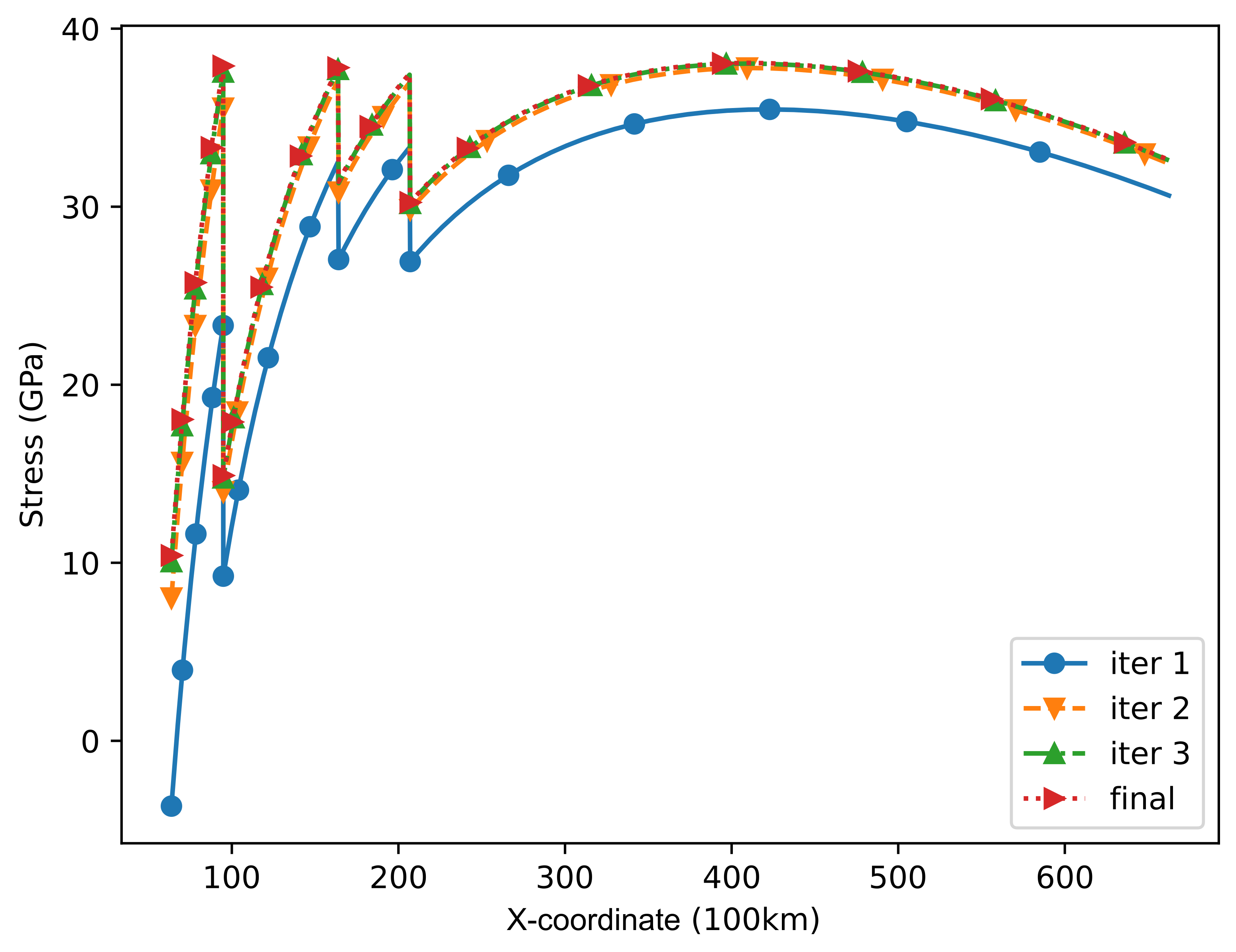
To verify the validity and precision of the methods proposed in this section, the anchor point is set on the equator. The calculation and theory stress distribution is shown in Figure 9.
The position coordinates of nodes cannot be automatically updated iteratively in ANSYS software, there is a great error between the calculation results of a single iteration and the theoretical stress. With the increase of iteration times, the final stress is close to the theoretical value, and the error is controlled within 10%.
With the same system parameters in Table 2, the stress distribution of a 4 segments space elevator is calculated. The mass of zenith anchor is 4.2 × 10⁹ and the design bearing capacity is 1 × 10⁹ . The cross-sectional area and the position of segments are shown in Table 3 and Table 4.
The calculated stress distribution is shown in Figure 10.
It can be seen from the figure that the stress of each segment is similar to that of a section of the constant cross-sectional space elevator model, rising evenly and reaching the peak at the highest part of the segment. When the stress rises to the section node, the stress will drop because the rope tension at both ends of the section node is the same, but the bearing cross-sectional area is different. At the same time, it can be seen that the strain accumulation effect of the rope has a greater impact on the rope section with lower position.
5.2. Optimization of Space Elevator Segments
Under the conditions that the initial cross-sectional area of the rope is 0.01 , the total height of the space elevator is 6 × 10⁴ , the mass of the connecting platform is 5 × 10⁴ , and the design bearing capacity is 1 × 10⁹ . The results of optimization calculation are shown in Table 5, Table 6 and Table 7.
The stress distribution of the space elevator system with segments from 2 to 6 is shown in Figure 11.
The results of analysis and optimization showed that the peak stress inside the rope decreased significantly with the increase of the number of segments. It can be seen that the segmented rope can effectively reduce the peak stress inside the rope and greatly reduce the strength requirements of the system on the rope material. However, the increase in the number of segments will lead to a significant increase in the cross-sectional area of segments near geosynchronous orbit. This is because the stress reduction of each section needs to increase the cross-sectional area of the previous section in proportion. If there are too many sections, the product effect will be very significant, which will greatly increase the mass of the space elevator system.
5.3. System Scale of Segmented Space Elevator System
Given the unique system parameters of the segmented space elevator system, parameters such as the number of segments, location of segments, and connecting platform have a great influence on the overall scale of the system. As the most basic system parameter of the segmented rope, the increase of the number of segments can effectively reduce the overall stress level of the system, but also greatly increase the mass of the connecting platform, affecting the scale of the rope. Thus, it is very important to choose the appropriate number of segments.
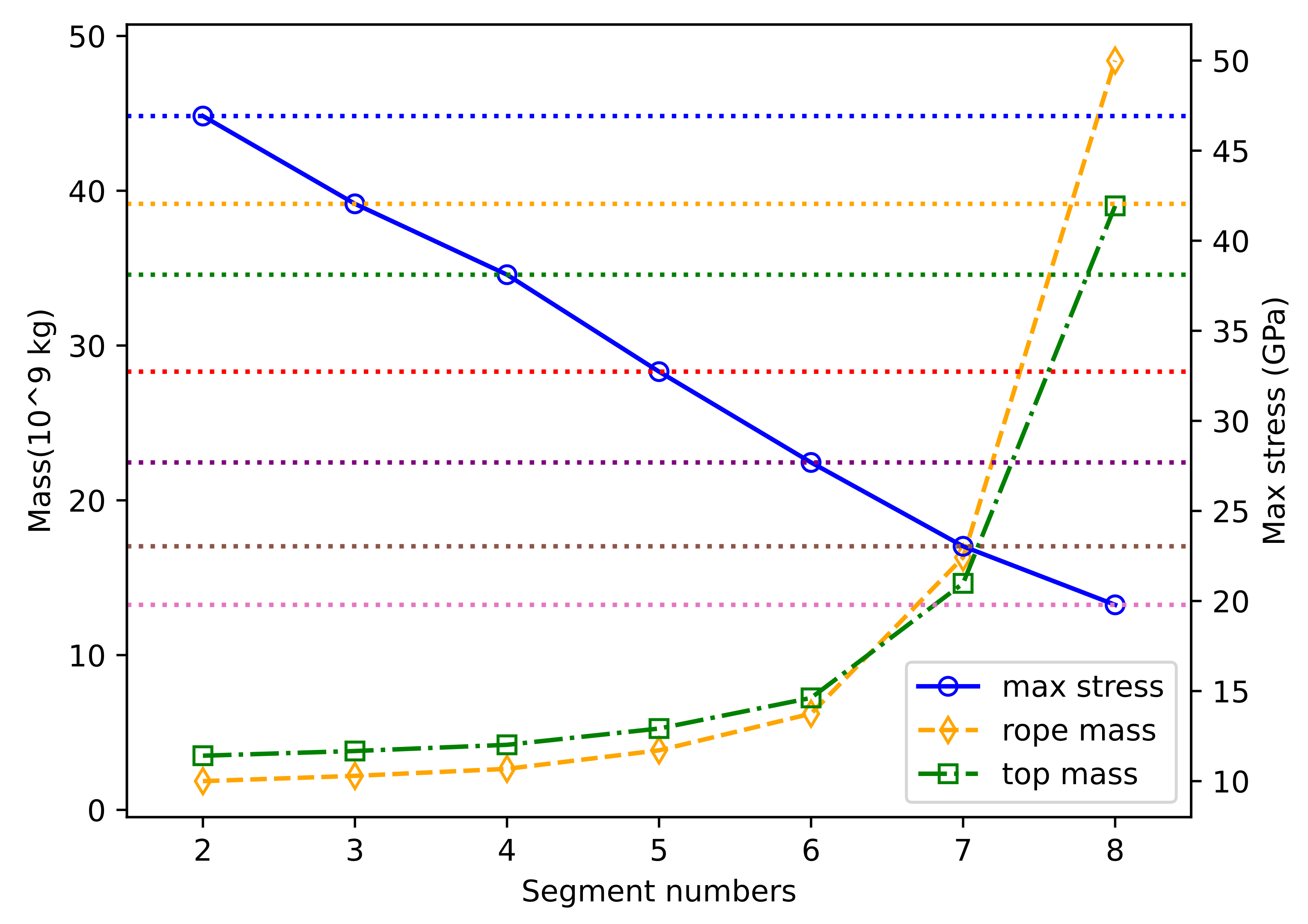
The calculation conditions are as follows: the initial cross-sectional area of the segmented space elevator rope is 0.01 , the total height of the space elevator is 60,000 km, the mass of the connecting platform is 50,000 km, and the design bearing capacity is 10 × 108 . The mass curve of the calculated segmented space elevator system with the number of segments from 2 to 8 is shown in Figure 12.
It can be seen from the figure that with the increase of the number of sections, the mass of each part of the system and the whole gradually increases. However, neither the total rope mass nor the zenith anchor mass increases linearly with the number of segments. When the number of segments reaches 6, the scale mass of the segmented space elevator system will approximately double with each additional segment, and the decrease of peak stress is much less than the increase of total mass. Therefore, under the conditions set in this case, it is best to use the 6-section space elevator rope configuration.
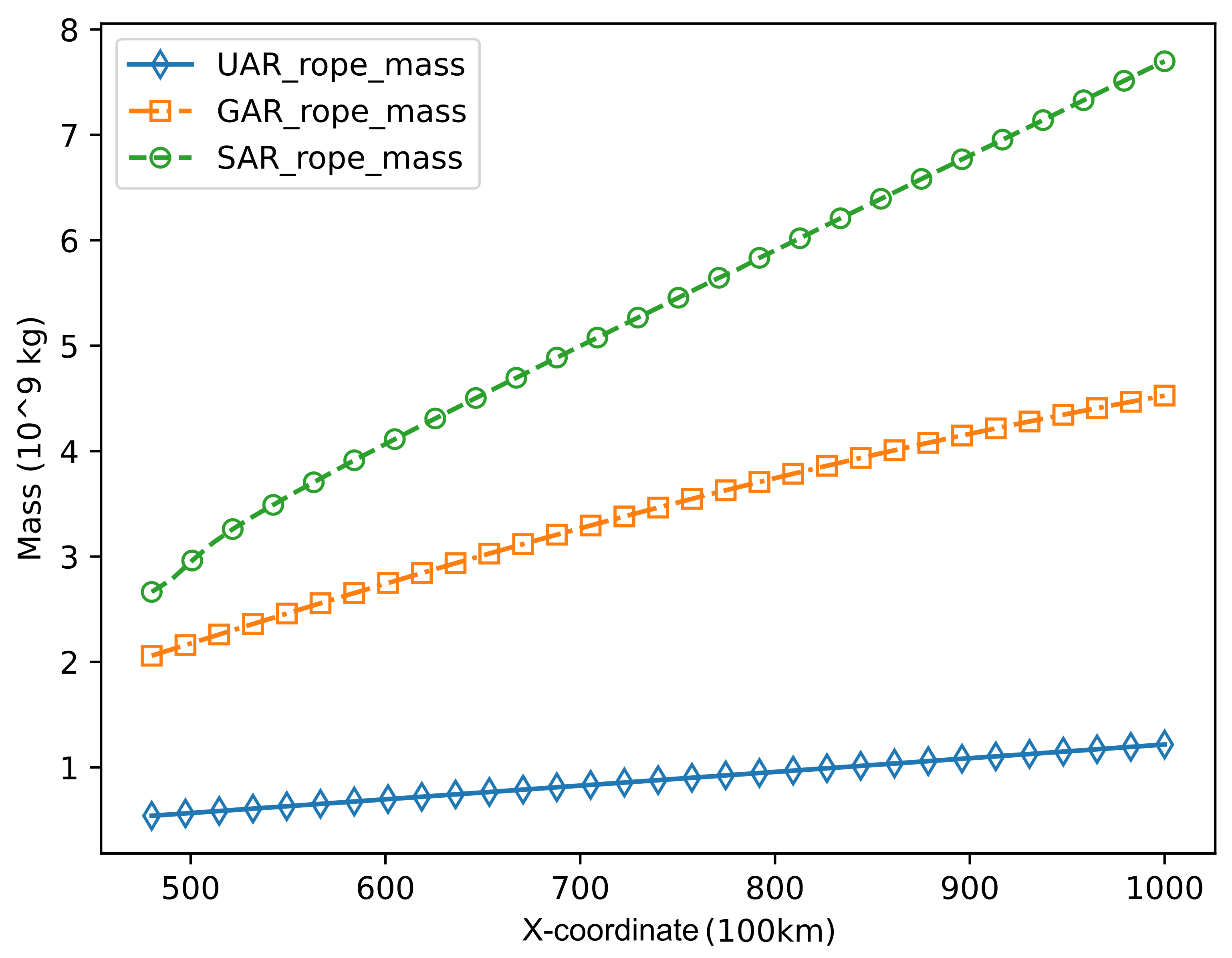
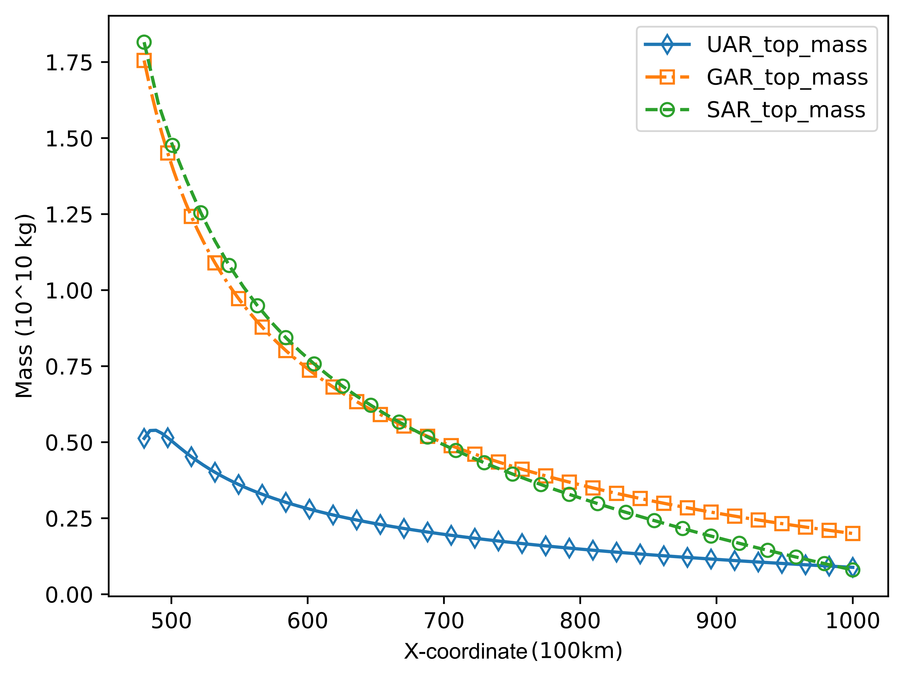
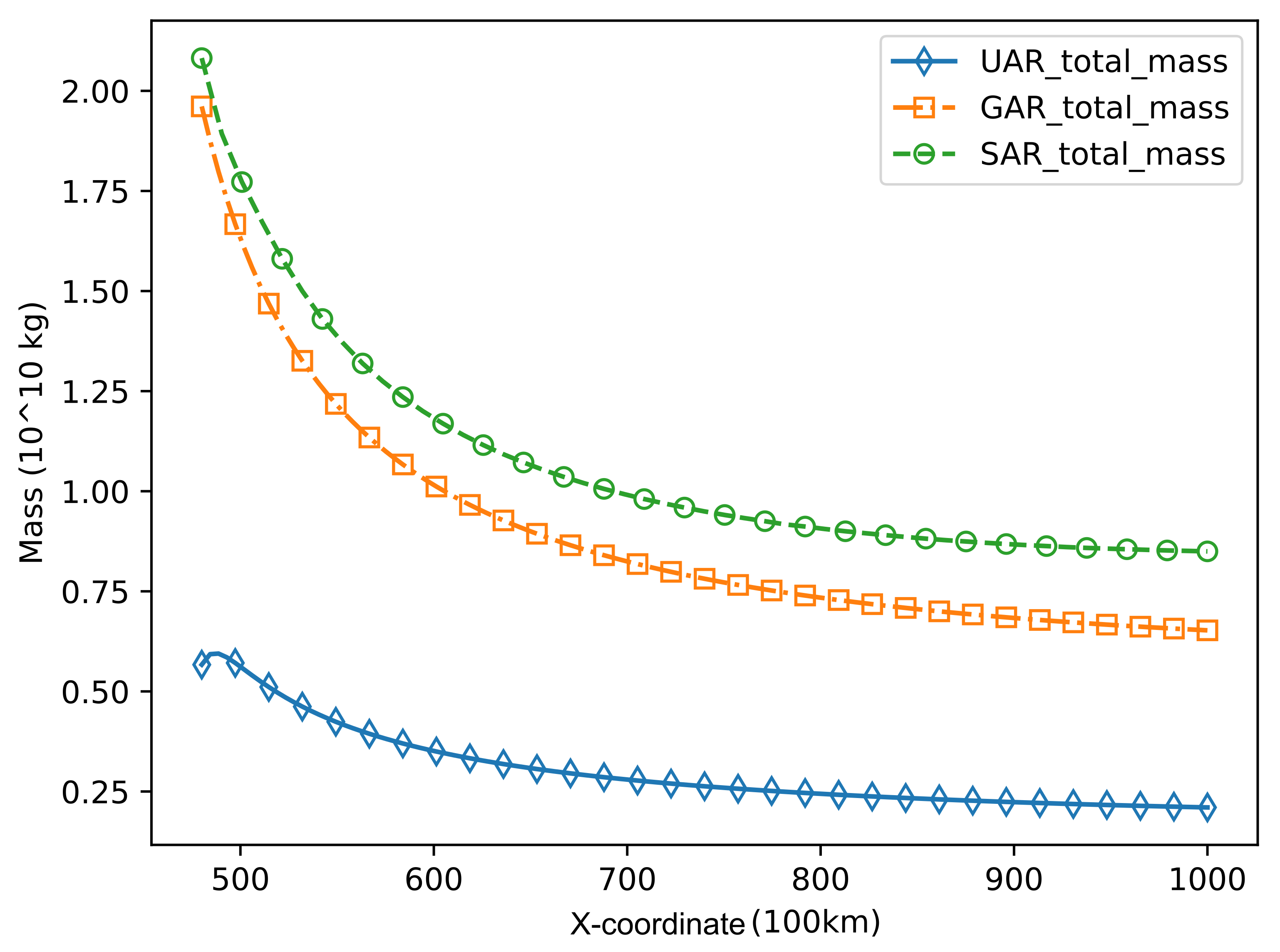
The total length of the space elevator rope is also an important factor affecting the scale of the space elevator system. When the total length of the space elevator rope changes within 48,000 km to 100,000 km, the relationship between the mass of each part of the space elevator system and the rope is obtained as shown in Figure 13, Figure 14 and Figure 15.
Due to the application of segmented rope, the mass of SAR space elevator system will be greater than the other two space elevator models under the same cross-section of ground anchor point. When the total length of the space elevator system is small, the mass of the zenith anchor of the SAR space elevator system and the GAR space elevator system is higher. However, with the increase of the total length of the space elevator system, the zenith anchor mass of the three space elevator systems will gradually decline, and the gap will gradually decrease. Since the rope mass of SAR space elevator system is larger than that of the other two models, the total scale of SAR space elevator system will be larger than that of GAR space elevator system and UAR space elevator system.
However, according to the characteristics of each space elevator system, although the system scale of the segmented space elevator system is larger than that of the UAR space elevator system and the GAR space elevator system, it has the characteristics of low rope stress peak, easy construction, and maintenance, and has a good application value.
6. Discussion
6.1. Calculation Errors in Iterative Methods
In the calculation of GAR space elevator system model, since the number of beam elements is limited, it is impossible to accurately compound the gradient section area change function. The force of each element is applied to the element nodes, resulting in the actual force of each element being slightly larger than the integration result. Therefore, the result of iterative calculation is larger than the theoretical value.
Using more finite element beam elements can make the cross section closer to the theoretical variation function of the cross-sectional area of the GAR space elevator system. At the same time, using higher-order beam element can make the force of the element closer to the reality. These methods can make the numerical results more accurate. However, compared with the results of non-iterative calculation, the accuracy of iterative calculation has been improved a lot.
For the UAR space elevator system model, the tension at the ground point cannot be 0, which is the critical state of the stability of the space elevator system. When the tension of the ground anchor point is negative, the structure of the space elevator will fail because the rope can only bear the tension but not the pressure. In the calculation of this paper, the tension at the ground anchor is set to 0 in order to put the stress of various methods at the same starting point and make the results comparable. In fact, the tensile force of the ground anchor end will be evenly added to the whole tether. By adjusting the mass of the zenith anchor, the stress distribution of the whole space elevator system can be shifted upward or downward, so as to align the stress of the ground anchor points.
6.2. Optimization of Space Elevator Segments
The stress of the tether outside the geosynchronous orbit is in a downward state under the condition of equal section, which does not affect the peak value of the rope stress of the overall space elevator system. Therefore, it is not segmented outside the geosynchronous orbit in this paper. However, if there are functional requirements of the space elevator system, it is also feasible to carry out segment design outside the geosynchronous orbit and such segments can easily not increase the peak stress of the system.
For the optimization calculation, without setting the segment position first, the optimization result is not unique. Therefore, in the actual optimization design, the approximate section position can be set through the functional requirements and other conditions. However, when the positions of all segment points are determined, the cross-sectional area of each segment has a definite solution under the optimal conditions. Therefore, when designing the segmented space elevator system, we can first determine the position of each segment point and calculate the cross-sectional area of each segment. Then, the number and position of segment points are readjusted through the increase of the cross-sectional area of each segment.
The maximum increase rate of sectional rope area is set as 120% in this paper. This parameter can be set according to the actual situation. However, if the increase rate is high, the overall mass scale will increase fast.
7. Conclusions
Combining with the design advantages of traditional space elevator model, in this paper, a new type of segmented space elevator model is designed. For the segmented space elevator system, the numerical calculation method of stress distribution is given, and its correctness is verified. Based on the numerical calculation of the stress of the space elevator system, the optimization method of the segment point and the cross-sectional area of each segment is given. Compared with the traditional space elevator model, the scale of the segmented space elevator system is analyzed.
The main conclusions are as follows:
- In this paper, a model of segmented space elevator system model is established. This model has the characteristics of easier construction, more practical functions and easier maintenance.
- The segmented space elevator model can significantly reduce the peak stress of the space elevator system under the condition of limited increase in the system scale, and the peak stress is 56% lower than that of the constant section space elevator model.
- Considering the number of segments, peak stress, and system scale, the calculation results show that the optimal number of segments is 5 or 6.
Segmented space elevator system has the advantages of easy construction, easy maintenance, and wide application. The characteristics of its low stress peak provide a new possibility for the actual construction of the space elevator system.
Author Contributions
Conceptualization, S.L.; methodology, S.L.; software, S.L.; validation, S.L.; formal analysis, S.L.; investigation, Y.F.; resources, Y.F. and N.C.; data curation, S.L.; writing—original draft preparation, S.L. and R.S.; writing—review and editing, Y.F. and R.S.; visualization, S.L.; supervision, Y.F. and N.C.; project administration, Y.F.; funding acquisition, N.C. and X.W. All authors have read and agreed to the published version of the manuscript.
Funding
This research was funded by the National Natural Science Foundation of China (10772057).
Institutional Review Board Statement
Not applicable.
Informed Consent Statement
Not applicable.
Data Availability Statement
Not applicable.
Conflicts of Interest
The authors declare no conflict of interest.
References
- Pearson, J. The orbital tower: A spacecraft launcher using the Earth’s rotational energy. Acta Astronaut. 1975, 2, 785–799. [Google Scholar] [CrossRef]
- Iijima, S. Helical microtubules of graphitic carbon. Nature 1991, 354, 56–58. [Google Scholar] [CrossRef]
- Edwards, B.C. Design and deployment of a space elevator. Acta Astronaut. 2000, 47, 735–744. [Google Scholar] [CrossRef]
- Swan, P.; Fitzgerald, M. Space elevator maturing into a Galactic Harbour. Acta Astronaut. 2018, 152, 123–126. [Google Scholar] [CrossRef]
- Harris, T.M.; Eranki, P.L.; Landis, A.E. Life cycle assessment of proposed space elevator designs. Acta Astronaut. 2019, 161, 465–474. [Google Scholar] [CrossRef]
- Shi, G.; Li, G.; Zhu, Z.; Zhu, Z.H. Dynamics and operation optimization of partial space elevator with multiple climbers. Adv. Space Res. 2019, 63, 3213–3222. [Google Scholar] [CrossRef]
- Huang, P.; Zhang, F.; Chen, L.; Meng, Z.; Zhang, Y.; Liu, Z.; Hu, Y. A review of space tether in new applications. Nonlinear Dyn. 2018, 94, 1–19. [Google Scholar] [CrossRef]
- Zhao, C.; Huo, M.; Qi, J.; Cao, S.; Zhu, D.; Sun, L.; Sun, H.; Qi, N. Coupled attitude-vibration analysis of an E-sail using absolute nodal coordinate formulation. Astrodynamics 2020, 4, 249–263. [Google Scholar] [CrossRef]
- Shan, M.; Guo, J.; Gill, E. Deployment dynamics of tethered-net for space debris removal. Acta Astronaut. 2017, 132, 293–302. [Google Scholar] [CrossRef]
- Luo, C.; Sun, J.; Wen, H.; Jin, D. Dynamics of a tethered satellite formation for space exploration modeled via ANCF. Acta Astronaut. 2020, 177, 882–890. [Google Scholar] [CrossRef]
- Okino, T.; Yamagiwa, Y.; Arita, S.; Ishikawa, Y.; Otsuka, K. Three-dimensional analysis of a counterweight type space elevator. Acta Astronaut. 2021, 185, 132–139. [Google Scholar] [CrossRef]
- Aravind, P. The physics of the space elevator. Am. J. Phys. 2007, 75, 125–130. [Google Scholar] [CrossRef] [Green Version]
- Cohen, S.S.; Misra, A.K. Elastic Oscillations of the Space Elevator Ribbon. J. Guid. Control. Dyn. 2007, 30, 1711–1717. [Google Scholar] [CrossRef]
- Zhenkun, W.; Naigang, C.; Youhua, F.; Bingli, L. Analysis of Stability and Dynamic Response of Elevator System. Harbin Gongye Daxue Xuebao/J. Harbin Inst. Technol. 2019, 51, 30–36. [Google Scholar] [CrossRef]
- Keshmiri, M.; Misra, A.; Modi, V. General formulation for N-body tethered satellite system dynamics. J. Guid. Control Dyn. 1996, 19, 75–83. [Google Scholar] [CrossRef]
- Woo, P.; Misra, A.K. Mechanics of very long tethered systems. Acta Astronaut. 2013, 87, 153–162. [Google Scholar] [CrossRef]
- Williams, P. Dynamic multibody modeling for tethered space elevators. Acta Astronaut. 2009, 65, 399–422. [Google Scholar] [CrossRef]
- Wang, Z.; Fan, Y.; Cui, N.; Liu, D. Non-equatorial space elevator design approach. Proc. Inst. Mech. Eng. Part J. Aerosp. Eng. 2019, 233, 3235–3243. [Google Scholar] [CrossRef]
- Li, G.; Shi, G.; Zhu, Z.H. Three-Dimensional High-Fidelity Dynamic Modeling of Tether Transportation System with Multiple Climbers. J. Guid. Control. Dyn. 2019, 42, 1797–1811. [Google Scholar] [CrossRef]
- Hu, W.; Zhang, C.; Deng, Z. Vibration and elastic wave propagation in spatial flexible damping panel attached to four special springs. Commun. Nonlinear Sci. Numer. Simul. 2020, 84, 105199. [Google Scholar] [CrossRef]
- Yoon, J.Y.; Song, W.K.; Park, N.C. Experiment and analysis of a space tether with pendulum-type elastic metamaterials. Int. J. Mech. Sci. 2020, 177, 105557. [Google Scholar] [CrossRef]
- Luo, S.; Fan, Y.; Cui, N. Application of Absolute Nodal Coordinate Formulation in Calculation of Space Elevator System. Appl. Sci. 2021, 11, 11576. [Google Scholar] [CrossRef]
- Ishikawa, Y.; Fuchita, Y.; Hitomi, T.; Inoue, Y.; Karita, M.; Hayashi, K.; Nakano, T.; Baba, N. Survivability of carbon nanotubes in space. Acta Astronaut. 2019, 165, 129–138. [Google Scholar] [CrossRef]
- Box, M.J. A New Method of Constrained Optimization and a Comparison With Other Methods. Comput. J. 1965, 8, 42–52. [Google Scholar] [CrossRef]
Figure 1.
Schematic diagram of segmented space elevator system model.

Figure 2.
Detailed structure of segmented space elevator system model.

Figure 3.
Specific position function of segmented space elevator system model.

Figure 4.
Build stage of segmented space elevator system model.

Figure 5.
Force analysis of the rope micro-segment.

Figure 6.
Numerical method for theoretical stress calculation of space elevator system.

Figure 7.
Typical stress distribution diagram of space elevator system with uniform cross-sectional area rope (UAR) and segmented cross-sectional area rope (SAR).
Figure 7.
Typical stress distribution diagram of space elevator system with uniform cross-sectional area rope (UAR) and segmented cross-sectional area rope (SAR).

Figure 8.
Design grid between the equatorial radius and the radius of geosynchronous orbit.

Figure 9.
Stress distribution diagram of gradual section space elevator system by different methods.
Figure 9.
Stress distribution diagram of gradual section space elevator system by different methods.

Figure 10.
Stress distribution diagram of segment section space elevator system.

Figure 11.
Stress distribution diagram of segmented space elevator system with 2 to 6 segments.

Figure 12.
Maximum stress and mass curve of segmented space elevator system with 2 to 8 segments.

Figure 13.
Rope mass and rope length curve of three space elevator systems.

Figure 14.
Zenith anchor mass and rope length curve of three space elevator systems.

Figure 15.
Total mass and rope length curve of three space elevator systems.


Table 1.
Parameters of space elevator systems.
| Rope Type | Cross-Sectional Area of Segment 1 | Cross-Sectional Area of Segment 2 | Segment Point |
| UAR | 0.01 | ||
| SAR 1 | 0.01 | 0.012 | 2.43 × 10⁴ |
| SAR 2 | 0.01 | 0.012 | 2.78 × 10⁴ |
| SAR 3 | 0.01 | 0.014 | 2.43 × 10⁴ |
Table 2.
System parameters.
| (m) | (m) | L (m) | E (Pa) | ||
|---|---|---|---|---|---|
| 6.37 × 10⁶ | 4.22 × 10⁷ | 3.99 × 10¹⁴ | 6 × 10⁷ | 1000 × 109 | 1300 |
Table 3.
Cross-sectional area of the segmented space elevator system.
| Segments | Segment 1 | Segment 2 | Segment 3 | Segment 4 |
| Cross-sectional area | 0.010 | 0.025 | 0.030 | 0.037 |
Table 4.
Section points of the segmented space elevator system.
| Segment Points | Segment Point 1 | Segment Point 2 | Segment Point 3 |
| Segment point position | 9.5 × 10³ | 16.4 × 10³ | 20.7 × 10³ |
Table 5.
Optimization results of rope section points of segmented space elevator system.
| Number of Segments | Segment Point 1 | Segment Point 2 | Segment Point 3 | Segment Point 4 | Segment Point 5 | Segment Point 6 | Segment Point 7 |
|---|---|---|---|---|---|---|---|
| 2 | 1.12 × 10⁴ | ||||||
| 3 | 1.02 × 10⁴ | 2.07 × 10⁴ | |||||
| 4 | 9.48 × 10³ | 1.64 × 10⁴ | 2.07 × 10⁴ | ||||
| 5 | 8.63 × 10³ | 1.28 × 10⁴ | 1.64 × 10⁴ | 2.07 × 10⁴ | |||
| 6 | 7.98 × 10³ | 1.07 × 10⁴ | 1.28 × 10⁴ | 1.64 × 10⁴ | 2.07 × 10⁴ | ||
| 7 | 7.19 × 10³ | 8.88 × 10³ | 1.07 × 10⁴ | 1.28 × 10⁴ | 1.64 × 10⁴ | 2.07 × 10⁴ | |
| 8 | 7.16 × 10³ | 8.34 × 10³ | 8.88 × 10³ | 1.07 × 10⁴ | 1.28 × 10⁴ | 1.64 × 10⁴ | 2.07 × 10⁴ |
Table 6.
Optimization results of sectional cross-sectional area of segmented space elevator system.
| Number of Segments | Segment 1 | Segment 2 | Segment 3 | Segment 4 | Segment 5 | Segment 6 | Segment 7 | Segment 8 |
|---|---|---|---|---|---|---|---|---|
| 1 | 0.010 | |||||||
| 2 | 0.010 | 0.025 | ||||||
| 3 | 0.010 | 0.025 | 0.030 | |||||
| 4 | 0.010 | 0.025 | 0.030 | 0.037 | ||||
| 5 | 0.010 | 0.025 | 0.034 | 0.042 | 0.055 | |||
| 6 | 0.010 | 0.025 | 0.035 | 0.051 | 0.065 | 0.091 | ||
| 7 | 0.010 | 0.025 | 0.044 | 0.068 | 0.106 | 0.154 | 0.246 | |
| 8 | 0.010 | 0.020 | 0.041 | 0.078 | 0.148 | 0.321 | 0.557 | 0.726 |
Table 7.
Optimization results of maximum stress value of segmented space elevator system.
| Number of segments | 1 | 2 | 3 | 4 | 5 | 6 | 7 | 8 |
| Maximum stress | 63 | 46.92 | 40.25 | 38.11 | 32.73 | 27.69 | 23.04 | 19.79 |
Publisher’s Note: MDPI stays neutral with regard to jurisdictional claims in published maps and institutional affiliations. |
© 2022 by the authors. Licensee MDPI, Basel, Switzerland. This article is an open access article distributed under the terms and conditions of the Creative Commons Attribution (CC BY) license (https://creativecommons.org/licenses/by/4.0/).
Share and Cite
MDPI and ACS Style
Luo, S.; Cui, N.; Wang, X.; Fan, Y.; Shi, R. Model and Optimization of the Tether for a Segmented Space Elevator. Aerospace 2022, 9, 278. https://0-doi-org.brum.beds.ac.uk/10.3390/aerospace9050278
AMA Style
Luo S, Cui N, Wang X, Fan Y, Shi R. Model and Optimization of the Tether for a Segmented Space Elevator. Aerospace. 2022; 9(5):278. https://0-doi-org.brum.beds.ac.uk/10.3390/aerospace9050278
Chicago/Turabian StyleLuo, Shihao, Naigang Cui, Xiaowei Wang, Youhua Fan, and Run Shi. 2022. "Model and Optimization of the Tether for a Segmented Space Elevator" Aerospace 9, no. 5: 278. https://0-doi-org.brum.beds.ac.uk/10.3390/aerospace9050278
Note that from the first issue of 2016, this journal uses article numbers instead of page numbers. See further details here.