
Fault-Tolerant Control of a Dual-Stator PMSM for the Full-Electric Propulsion of a Lightweight Fixed-Wing UAV


Department of Civil and Industrial Engineering, University of Pisa, Largo Lucio Lazzarino 2, 56122 Pisa, Italy
*
Author to whom correspondence should be addressed.
Aerospace 2022, 9(7), 337; https://0-doi-org.brum.beds.ac.uk/10.3390/aerospace9070337
Submission received: 9 May 2022
/
Revised: 10 June 2022
/
Accepted: 22 June 2022
/
Published: 24 June 2022
(This article belongs to the Special Issue Electro-Mechanical Actuators for Safety-Critical Aerospace Applications)
Abstract
:The reliability enhancement of electrical machines is one of the key enabling factors for spreading the full-electric propulsion to next-generation long-endurance UAVs. This paper deals with the fault-tolerant control design of a Full-Electric Propulsion System (FEPS) for a lightweight fixed-wing UAV, in which a dual-stator Permanent Magnet Synchronous Machine (PMSM) drives a twin-blade fixed-pitch propeller. The FEPS is designed to operate with both stators delivering power (active/active status) during climb, to maximize performances, while only one stator is used (active/stand-by status) in cruise and landing, to enhance reliability. To assess the fault-tolerant capabilities of the system, as well as to evaluate the impacts of its failure transients on the UAV performances, a detailed model of the FEPS (including three-phase electrical systems, digital regulators, drivetrain compliance and propeller loads) is integrated with the model of the UAV longitudinal dynamics, and the system response is characterized by injecting a phase-to-ground fault in the motor during different flight manoeuvres. The results show that, even after a stator failure, the fault-tolerant control permits the UAV to hold altitude and speed during cruise, to keep on climbing (even with reduced performances), and to safely manage the flight termination (requiring to stop and align the propeller blades with the UAV wing), by avoiding potentially dangerous torque ripples and structural vibrations.
1. Introduction
The global market size of Unmanned Aerial Vehicles (UAVs) was 27.4 billion USD in 2021 and, despite the negative impact of the COVID-19 pandemic, it is expected to grow within 2026 up to 58.4 billion USD, at a Compound Annual Growth Rate (CAGR) of 16.4% [1]. Additionally, pushed by the wider objectives of the aerospace electrification, the design of next-generation long-endurance UAVs is undoubtedly moving toward the use of Full-Electric Propulsion Systems (FEPSs). Although immature nowadays in terms of reliability and energy density (e.g., lithium-ion battery packs typically range about 300 kJ/kg, which is 100 times lower than gasoline [2]), FEPSs are expected to obtain large investments in the forthcoming years, aiming to replace the conventional internal combustion motors, as well as to outclass the hybrid or hydrogen-based solutions [3]. Coherently, the global market size of electric motors is projected to grow within 2028 up to 181.9 billion USD, at a CAGR of 7.0% [4]. In particular, the segment of Permanent Magnet Synchronous Machines (PMSMs) is forecast to hold more and more significant markets, due to their advantages in terms of power density, efficiency, low torque ripple and dynamic performances. In this context, the Italian Government and the Tuscany Regional Government co-funded the project TERSA (Tecnologie Elettriche e Radar per Sistemi aeromobili a pilotaggio remoto Autonomi) [5], led by Sky Eye Systems (Italy) in collaboration with the University of Pisa and other Italian industries.
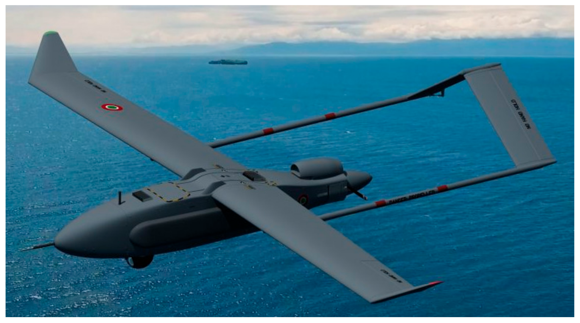
The TERSA project aims to develop an Unmanned Aerial System (UAS) with fixed-wing UAV, Figure 1, having the following main characteristics:
- Take-off weight: from 35 to 50 kg;
- Endurance: >6 h;
- Range: >3 km;
- Take-off system: pneumatic launcher;
- Landing system: parachute and airbags;
- Propulsion system: FEPS powering a twin-blade fixed-pitch propeller;
- Innovative sensing systems:
- ○
- Synthetic aperture radar, to support surveillance missions in adverse environmental conditions;
- ○
- Sense-and-avoid system, integrating a camera with a miniaturised radar, to support autonomous flight capabilities in emergency conditions.
With particular reference to the activities related to the TERSA UAV propulsion system development (which this work refers to), special attention has been dedicated to the demonstration of its fault-tolerant capabilities. It is well-known that, compared with solutions based on internal combustion motors, FEPSs on UAVs would guarantee smaller CO2 emissions, higher efficiency, lower noise, reduced thermal signature (crucial for military applications), higher service ceiling and simplified maintenance [6], but several reliability and safety issues are still open, especially for long-endurance flights in unsegregated airspaces. As relevant example, the failure rate of a simplex FEPS solution with a three-phase PMSM driven by three-leg converter typically ranges about 2.4 per thousand flight hours [7,8], which is far from the reliability and safety levels required for the airworthiness certification [9].
Provided that the weight and envelopes required by UAV applications impede the extensive use of hardware redundancy (e.g., redundant motors), the reliability enhancement of FEPSs can be achieved only through motor phase redundancy or by using unconventional converters. Different solutions are proposed in the literature, and they can be split in two categories: those applying conventional three-leg converters (using multiple phases [10,11] or multiple three-phase arrangements [12,13]), and those using four-leg converters [8,14,15]. In the latter solution, a couple of power switches are added as stand-by devices to the conventional three-leg bridge, enabling the control of the central point of the motor Y-connection. Although the four-leg solution permits to save weight, it requires an ad hoc design of the motor and its power electronics [8,16]. On the other hand, PMSMs with multiple three-phase arrangements are less compact, but they use conventional converters driven by standard techniques [13].
The failure rate of electric machines is essentially driven by faults on motor phases and converters (open-switch in a converter leg, open-phase, phase-to-ground fault, inter-turn short circuit, or capacitor short circuit [17]), that cover about 70% of the system fault modes [7]. Stator faults can initiate for different causes, such as dielectric breakdown, degradation of the winding insulation, thermal stress, overburden, or mechanical vibrations [18], and many research efforts have been carried out for their diagnosis and the compensation, especially for open-phase faults [8,19,20,21] and inter-turns short circuits [22,23,24,25], while the literature is poorer for phase-to-ground faults in electrical machines [26,27,28]. As discussed in [29], phase-to-ground faults fall into the short circuit faults category. Usually, a short circuit initiates as an inter-turn fault (very difficult to detect at an early stage), which typically evolves into a coil-to-coil, phase-to-phase, or into a phase-to-ground short circuit. Phase-to-ground faults are particularly dangerous, because they can cause irreversible damages to both windings and core. If the motor windings could be replaced, the core damage is irreversible and it requires the entire motor removal.
When addressing UAV applications, the basic consequence related to motor faults is the decrease or loss of thrust power, which essentially impacts on the altitude hold and/or climb capabilities of the vehicle. Together with other major UAV failures such as those affecting control actuators and sensors, the hazard mitigation requires the application of suitable fault-tolerant techniques. A comprehensive survey on methods for fault diagnosis and fault-tolerant control against UAV failures is provided by [30], and the reference highlights that the works addressing propulsion failures for fixed-wing UAVs is very limited. Most of the literature is actually focused on the effects of faults to control actuators and sensors for both single UAVs [31,32,33,34] and UAVs in formation flight [35,36,37], while the faults to propulsion systems are typically modelled with rough or very simplified approaches (e.g., total propulsion loss as in [38] or increase in the drivetrain friction as in [39]).
Together with reliability requirements, an FEPS for UAVs must have high compactness, high power-to-weight ratio, high torque density, and excellent efficiency. For these high-performance applications, Axial-Flux PMSMs (AFPMSMs) are preferred to conventional PMSMs with radial flux linkages [40]. In fact, although conventional PMSMs have higher technology readiness, AFPMSMs are superior in terms of weight (core material is reduced), torque-to-weight ratio (magnets are thinner), efficiency (rotor losses are minimized), and versatility (the axial air gaps are easily adjustable) [41,42,43]. The FEPS of the reference TERSA UAV is actually equipped with a dual-stator AFPMSM, capable of operating in both active/active and active/stand-by configurations to obtain fault-tolerant capabilities for the system [44].
This paper aims to contribute to the literature of FEPSs for fixed-wing UAVs by dealing with the fault-tolerant control design and the dynamic performance characterization of the TERSA UAV, particularly addressing the impacts of failure transients on both the motor and the vehicle performances in different flight phases (climb, cruise, flight termination/landing) if a phase-to-ground short circuit in a stator is simulated.
The basic objective of the investigation is, through a detailed fault modelling, to characterise both the fault symptoms (at both the motor level and UAV level) and the failure transients related to the application of fault-tolerant techniques. For this reason, the paper does not include the description of the health-monitoring algorithms, but it simply assumes that they exist and are capable of detecting the fault with a pre-defined latency; after that a compensation is applied (the failed stator is de-energized and the control on healthy one is activated or reconfigured).
The work is articulated as follows: the first part is dedicated to the system description and to the nonlinear FEPS model; successively, the main features of the fault-tolerant control design are presented. Finally, an excerpt of simulation results is proposed, by highlighting and discussing the effects of a phase-to-ground fault during different flight manoeuvres, and by demonstrating the effectiveness of the proposed design.
2. Materials and Methods
2.1. FEPS Description
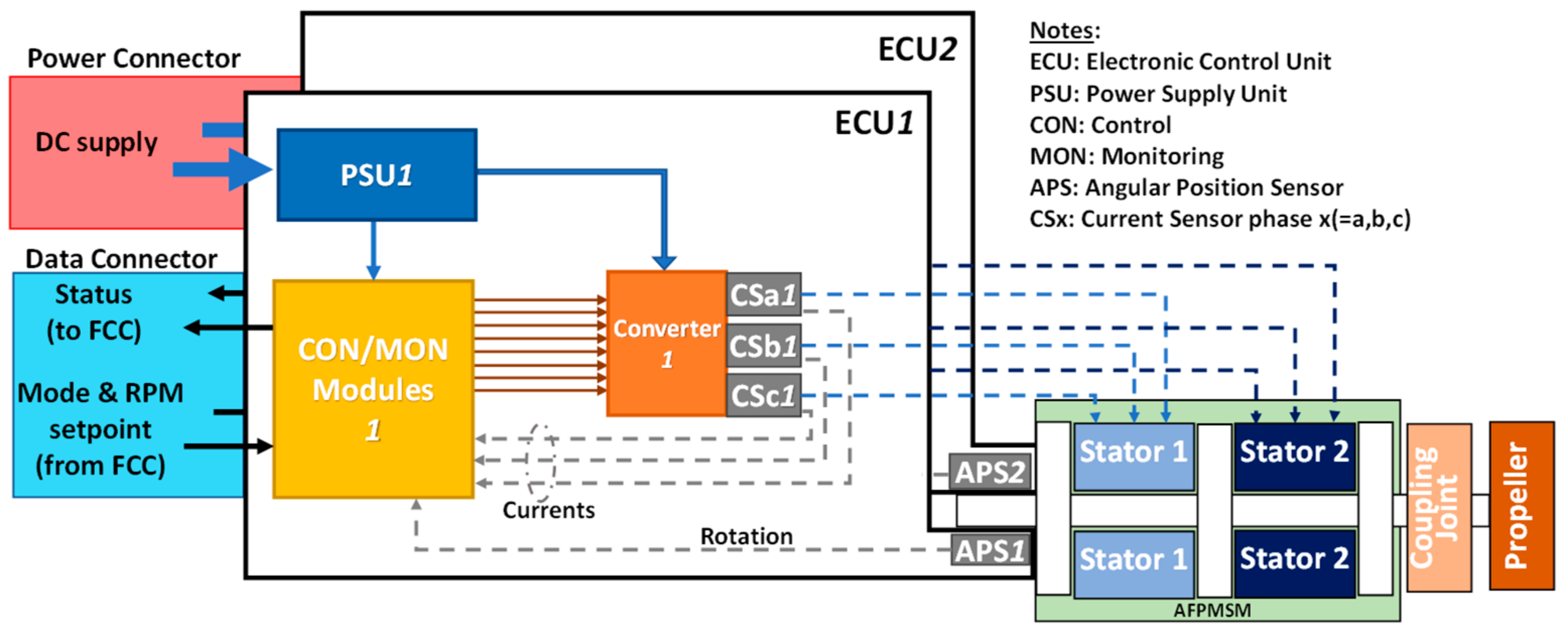
The fault-tolerant FEPS of the TERSA UAV is basically composed of (Figure 2):
- Dual-stator AFPMSM, with surface-mounted magnets and phases in Y connection;
- Twin-blade fixed-pitch propeller (APC22 × 10E model [45]);
- Mechanical coupling joint between motor shaft and propeller;
- Two Electronic Control Units (ECUs), each one including:
- ○
- Control/monitoring (CON/MON) module, for the implementation of the closed-loop control and health-monitoring functions;
- ○
- Conventional three-leg converter;
- ○
- Three Current Sensors (CSa, CSb, CSc), one per each motor phase;
- ○
- Angular Position Sensor (APS), measuring the motor rotation;
- ○
- Power Supply Unit (PSU), providing all ECU components with the required electrical supply;
- Two interface connectors, one for the electrical power input and the other for the data exchange with the Flight Control Computer (FCC).
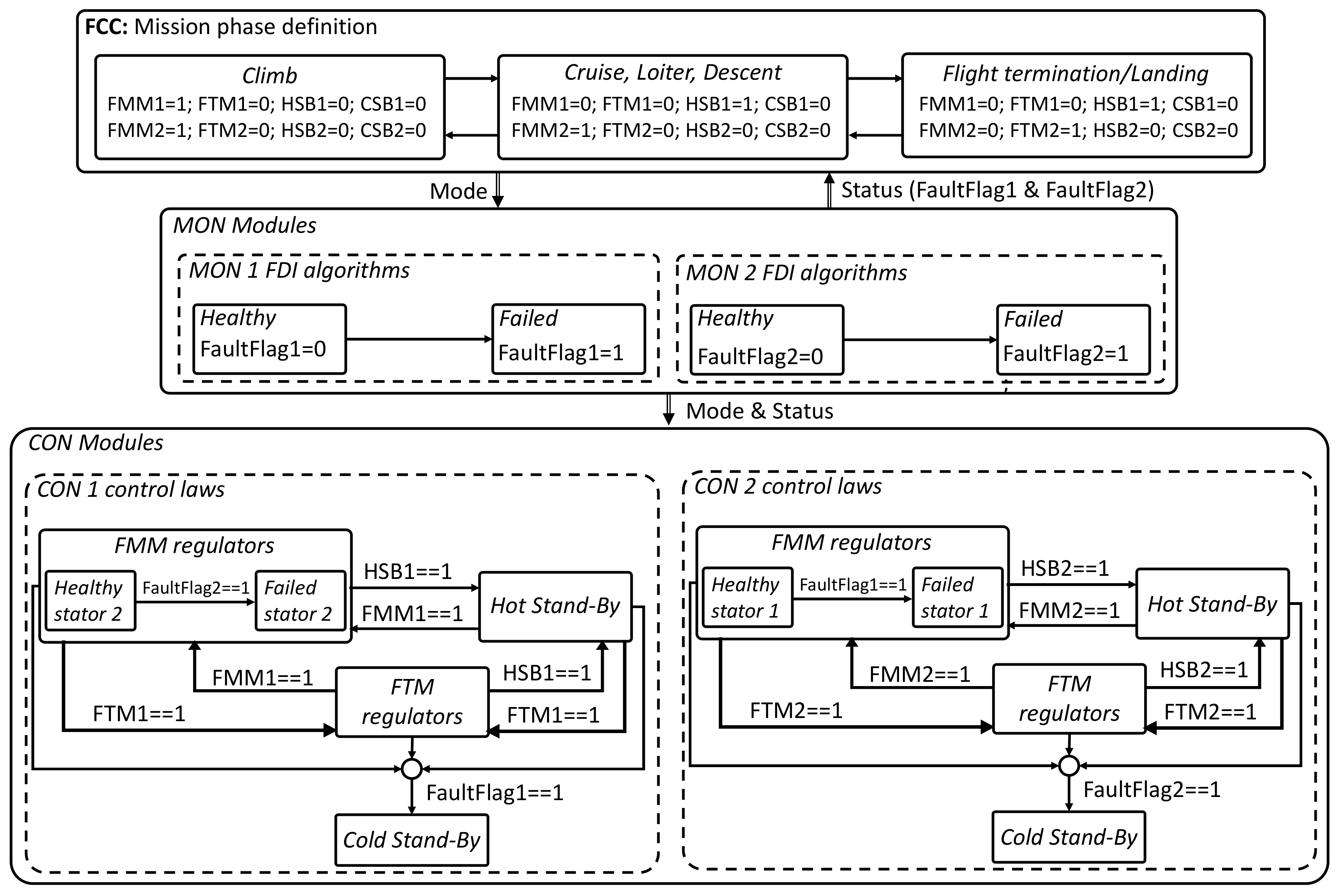
The fault-tolerant FEPS is designed to guarantee mission accomplishment even after the failure of one of the two AFPMSM stators. Different operations of the stators are thus defined by the CON/MON modules, so that each stator can
- Be electrically supplied and controlled to apply an electrical torque on the motor shaft (active status);
- Be electrically supplied at the converter level to be prompt to operate, but with open/isolated phases, so that no torque is applied (stand-by status);
- Be de-energized at the converter level (passive status).
In addition, since the UAV flight termination and landing is obtained by deploying a parachute and by inflating airbags to be used as landing gears, the propeller blades must be aligned with the wing before opening the parachute to avoid interferences, and a specific control mode must be foreseen. As a consequence, four operation modes have been defined to control each stator of the AFPMSM:
- (1)
- Flight Mission Mode (FMM), in which the stator is active and a speed-tracking closed-loop system is implemented, by means of two nested loops, on motor speed and currents (via Field-Oriented Control, FOC), respectively;
- (2)
- Flight Termination Mode (FTM), in which the stator is active and controlled via three nested loops: the two ones of the FMM plus an outer loop on motor shaft rotation, with a predefined setpoint for the propeller alignment;
- (3)
- Hot Stand-By (HSB), in which the stator is in stand-by status;
- (4)
- Cold Stand-By (CSB), in which the stator is passive.
2.2. Mechanical Transmission and Propeller Loads Modelling
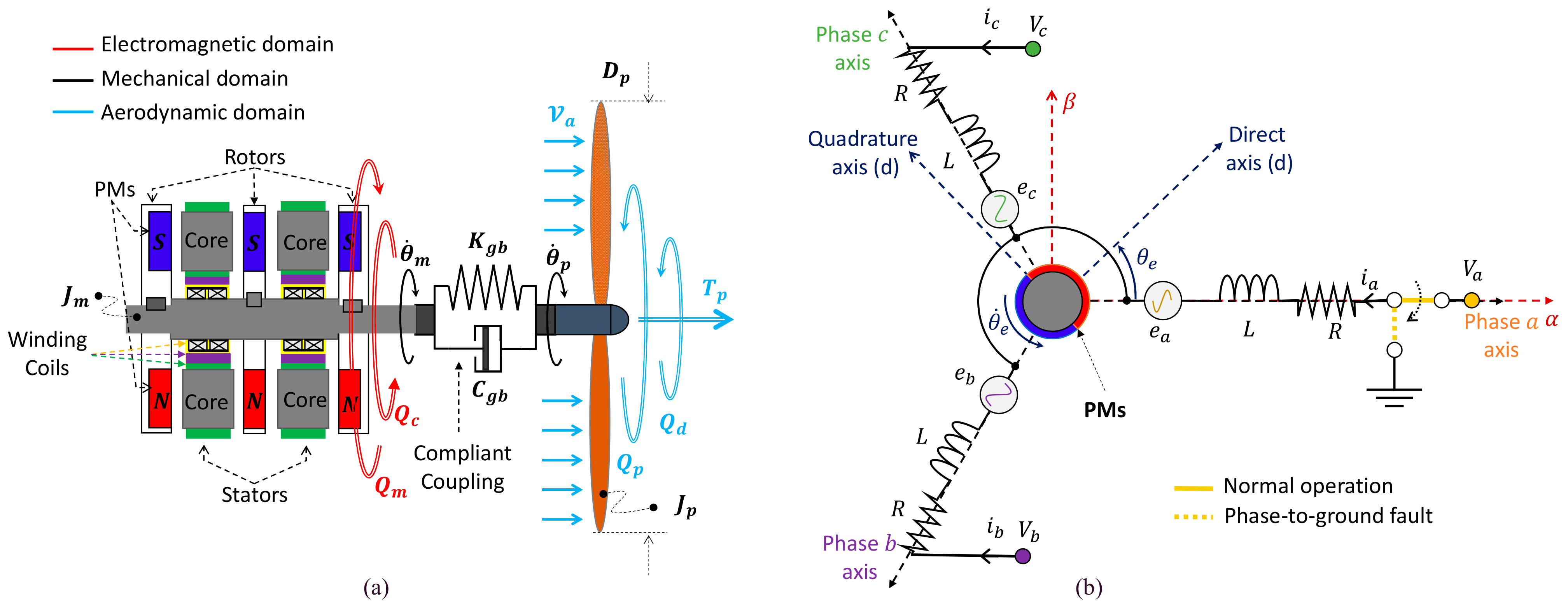
The dynamics of the aero-mechanical section of the FEPS, providing the UAV with the thrust , is schematically depicted in Figure 4a and is modelled by [8,12]:
where and , and are the inertias and angles of the propeller and the motor shafts, respectively, is the propeller torque, is a gust-induced disturbance torque, is the motor torque, is the cogging torque and is its maximum amplitude, is the pole pairs number, is the harmonic index of the cogging disturbance, while and are the stiffness and the damping of the mechanical coupling joint.
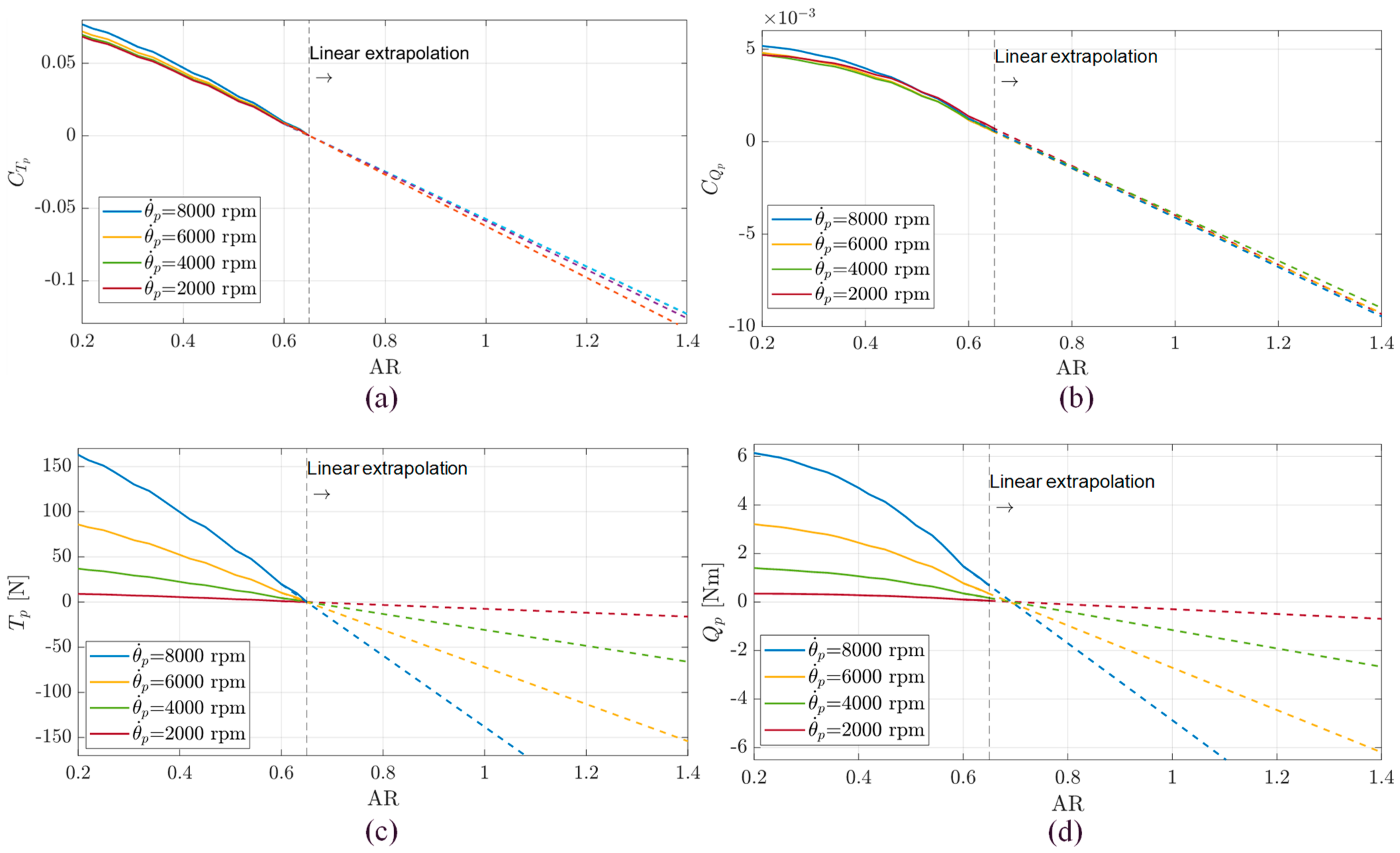
Concerning the aerodynamic torque, the FEPS is equipped with the twin-blade fixed-pitch composite propeller APC22 × 10E, which is characterized by the following thrust and torque expressions:
where and are the nondimensional thrust and torque coefficients, AR is the propeller advance ratio, is the propeller diameter, is the air density, and is the UAV forward speed.
It is worth noting that the manufacturer database provides the nondimensional coefficients and only for AR < 0.65 [45]. This range adequately covers the FEPS operating conditions in FMM (Table 1), but it is not adequate for the FTM, where AR theoretically tends to infinite (because the propeller stops rotating), so that a loads model extension was carried out. This was carried out via Equation (5), by linearly extrapolating the coefficient trends at AR* = 0.65 (Figure 5), with an approach that typically provides conservative estimates [46,47].
In Equation (5), represents the thrust (X = T) or torque (X = Q) propeller coefficient, while is the related quantity given in the manufacturer database.
2.3. Three-Phase PMSM Modelling
Apart from the architectural dissimilarity from a conventional radial-flux PMSM, the mathematical modelling of a AFPMSM is essentially identical [48,49]. With reference to the schematics in Figure 4b, and under the following assumptions [13]:
- Negligible magnetic nonlinearities of ferromagnetic parts (i.e., hysteresis, saturation);
- Each stator–rotor module is magnetically symmetric with reference to phases;
- Permanent magnets are surface-mounted, are made of rare-earth materials, and the magnet reluctance along the quadrature axis is infinite with respect to the one along the direct axis;
- Negligible magnetic coupling among phases;
- Negligible magnetic flux dispersions (i.e., secondary paths, iron losses).
In Equations (5)–(6), is the applied voltages vector, is the stator currents vector, is the back-electromotive forces vector, and are the resistance and inductance of the phases, is the magnet flux linkage, and is the neutral point voltage. The motor torque ( is thus given by:
More conveniently, the motor torque can be expressed with reference to quantities in the rotating reference frame, by applying the Clarke–Park transformations [13], so that:
where and are the current vectors in the Clark and Clark–Park reference frames, respectively. By using Equation (7), we finally have:
in which is the motor torque constant.
2.4. Fault-Tolerant Control System Design
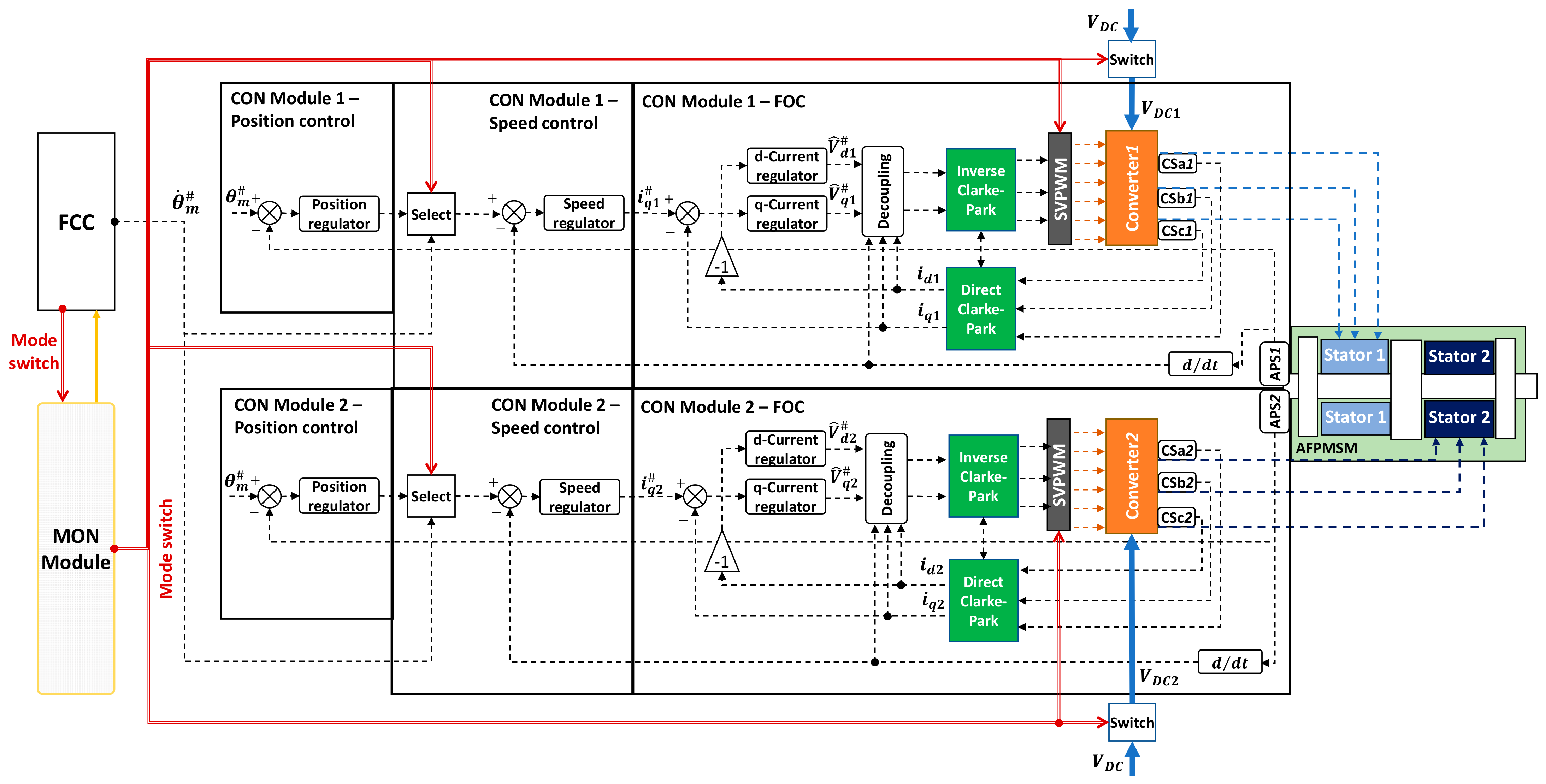
The multi-mode closed-loop system of the FEPS, schematically depicted in Figure 6, has been entirely developed as a finite-state machine, by using the Matlab–Simulink–Stateflow tools, with mode switch signals that can be generated by the MON modules or overridden by the commands sent by the FCC. In FMM (Table 1), the CON modules receive the speed setpoint () from the FCC, while in FTM the angle setpoint () is constant and pre-defined.
In the CON modules, all the regulators implement digital signal processing and apply proportional/integral actions on tracking error signals, plus an anti-windup function with back-calculation technique to compensate for command saturation. In particular, the generic j-th digital regulator (with j = C, S and R, indicating the current, speed and rotation loops, respectively, Table A3) is governed by Equations (12)–(13):
where is the discrete-time operator, is the regulator input (tracking error), is the regulator output, is the saturator block input (proportional–integral with reference to error, if no saturation is present), while and are the proportional and integral gains, is the back-calculation anti-windup gain, is the saturation limit, and is the sampling rate, Table A3.
In the MON modules, a set of monitoring algorithms are real-time executed at 10 kHz sampling rate, to detect and isolate the major FEPS faults (open-phase, shorted-phase, overheating, overcurrent, hardover, jamming, etc.), and to define the correct operation mode of the AFPMSM stators (Table 1). The maximum fault detection latency for all health-monitoring algorithms was set to 250 ms and the FEPS failure transients will be thus characterized in Section 3 with reference to this worst-case scenario.
2.5. UAV Longitudinal Dynamics Modelling
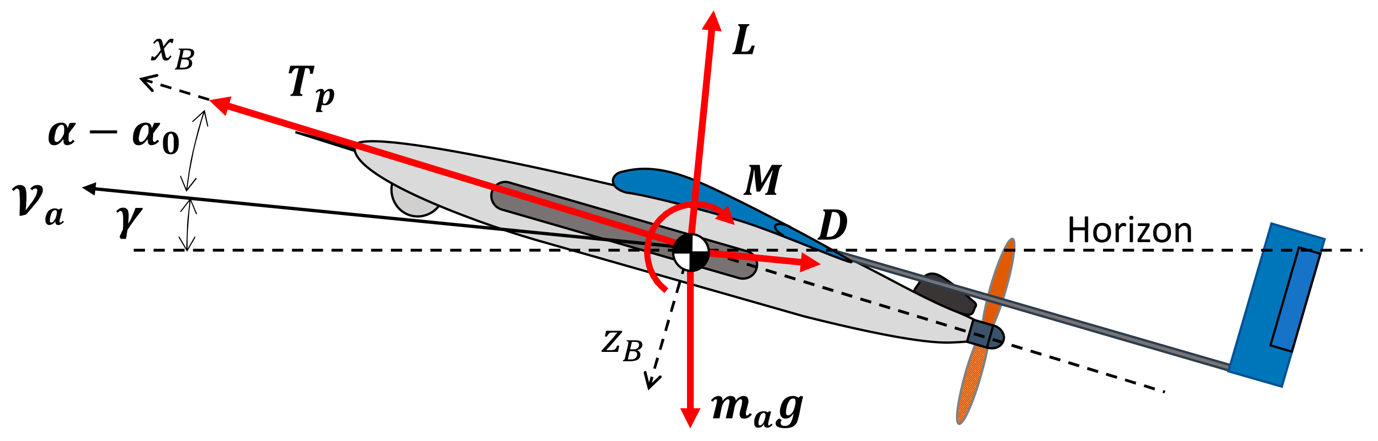
The UAV dynamics is simulated via a reduced-order model, by taking into account the longitudinal phugoid behaviour only (Figure 7). By assuming that:
- The thrust is aligned with the body frame axis ();
- The aerodynamic coefficients related to the wing downwash and to the pitch rate are negligible;
- The elevator deflection () continuously implies the pitch equilibrium;
- The angle-of-attack, the path angle and the elevator deflection are small quantities.
The UAV dynamics can be thus described by Equations (14)–(15), [50]:
where
In Equations (14)–(15), , , , and () are the UAV mass, forward speed, path angle, and (zero-lift) angle-of-attack; , , and are the UAV lift, drag and thrust (Figure 3a and Figure 7); is the total aerodynamic pitch moment; is the wing area; is the UAV mean aerodynamic chord; is the base pitch moment coefficient; and are the pitch moment–slope coefficients; and and are the lift–slope coefficients, while and are the zero-lift drag coefficient and the induced drag factor, respectively.
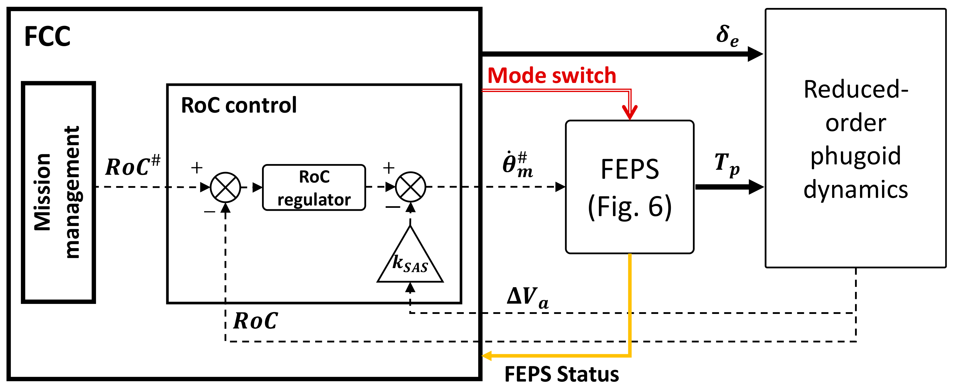
To evaluate the impacts of motor failures at the vehicle level, the system simulation also includes the closed-loop control on the UAV Rate-of-Climb (RoC, Equation (16)), as described by the scheme in Figure 8.
The RoC regulator receives the setpoint () from the mission management functions and implements a proportional/integral action on the tracking error with back-calculation anti-windup (similarly to FEPS ones, the regulator is governed by Equations (12)–(13), in which j = RoC, Table A3). In addition, a stability augmentation system related to advance speed perturbation (loop with gain in Figure 8) is also applied.
3. Results
3.1. Simulation Campaign Definition
The performances of the fault-tolerant FEPS were assessed by using a MATLAB/Simulink model of the complete system and numerically solved via the fourth-order Runge–Kutta method, using a 10−6 s integration step. It is worth noting that the choice of a fixed-step solver is not strictly related to the objectives of this work (in which the model is used for “off-line” simulations), but it has been selected for the next steps of the project, when the control system will be implemented in the ECU boards via automatic MATLAB compilers and executed in “real-time”.
The fault-tolerant capabilities of the FEPS are tested by injecting a phase-to-ground fault in the phase A of the stator 2 (Figure 4b) in different flight manoeuvres, i.e.:
- During climb, in which the MON modules detect the fault and switch the CON modules to operate from FMM/FMM (normal operation) to FMM/CSB (fail-operative);
- During cruise, in which the MON modules detect the fault and switch the CON modules to operate from HSB/FMM (normal operation) to FMM/CSB (fail-operative);
- During flight termination/landing, in which the MON modules firstly detect the fault and switch the CON modules to operate from HSB/FMM (normal operation) to FMM/CSB (fail-operative), and then impose the transition from FMM to FTM on the active stator when the speed is adequately small.All the tests are executed by simulating the following sequence of events:
- Start (t = 0 s): the FEPS works in normal operation (no faults) and drives the propeller at 5800 rpm with the UAV at 26 m/s in level flight at sea altitude;
- FEPS command (t = 1 s), i.e.,
- ○
- For climb, the maximum RoC of 3.5 m/s is requested by the FCC;
- ○
- For cruise, the propeller speed setpoint is held;
- ○
- For flight termination/landing, the propeller speed setpoint is decreased from the cruise value at a −60 rad/s2 rate;
- Event 1 (E1, fault injection): a phase-to-ground fault on phase a of stator 2 is imposed;
- Event 2 (E2, fault detection and isolation): a CSB mode is set on the faulty stator;
- Event 3 (E3, fault compensation):
- ○
- For climb, the current demand for the healthy stator is doubled and the RoC setpoint is reduced to 1 m/s;
- ○
- For cruise and flight termination/landing, the healthy stator is activated (250 ms delay is assumed to achieve the full electric supply) and controlled;
- Event 4 (E4, only for flight termination/landing): the active stator is switched to operate from FMM to FTM.
To permit the evaluation of failure transient impacts on system performances, the results of two simulations will be proposed in Section 3.2, Section 3.3 and Section 3.4 by applying or not the system health monitoring, so that a comparison between uncompensated and compensated behaviours is documented.
3.2. Failure Transients in Climb
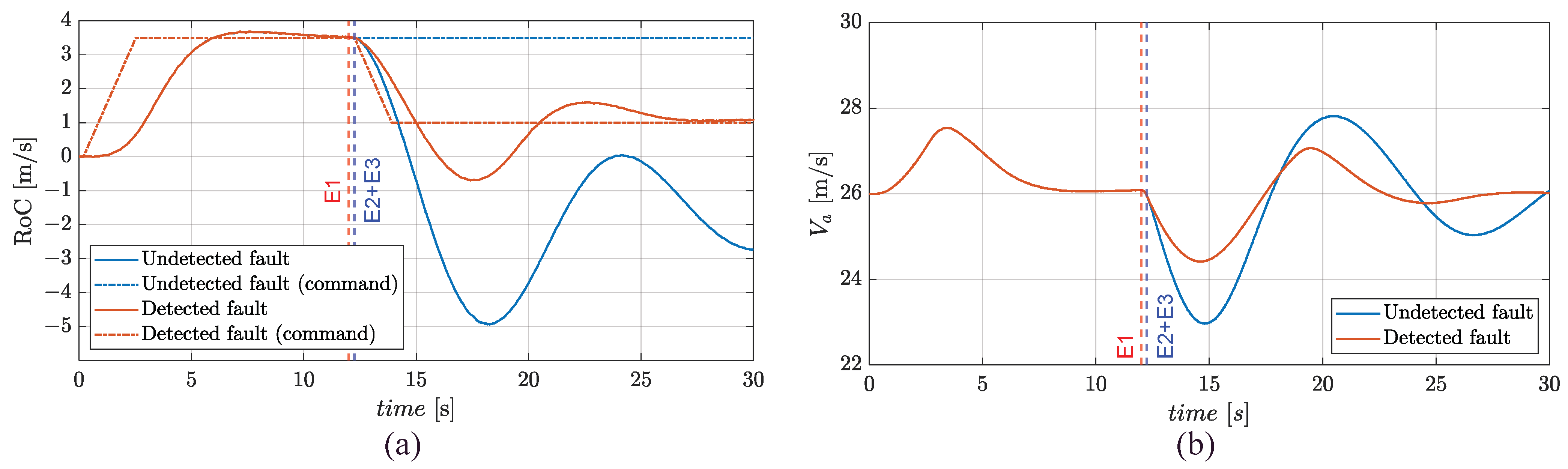
The simulations can be described with reference to Figure 9: firstly, the tracking performances of the closed-loop control on RoC are assessed, by requesting (t = 1 s) the UAV to achieve the maximum-climb rate (3.5 m/s) at 1.5g load factor; secondly, for both simulations, E1 is imposed while the UAV is performing a steady climb (t = 12 s). In one of the two simulations, the fault is detected and compensated (E2+E3, at t = 12.25 s), and the CON modules switch to operate from FMM/FMM to FMM/CSB.
In the healthy condition, the RoC tracking is characterized by a rise time of about 5 s and negligible overshoot, Figure 9a. An undetected phase-to-ground fault drastically impacts on performances: without detection, the RoC actually goes below zero, meaning that the UAV follows a descent motion. On the other hand, the fault compensation permits to hold the UAV in climb, even if with reduced performance. If the fault is not detected, the airspeed exhibits relevant oscillations (with about a 12 s period, close to the Lanchester’s phugoid prediction, i.e., , [51]), while it rapidly recovers the cruise value if the health-monitoring is applied, Figure 9b.
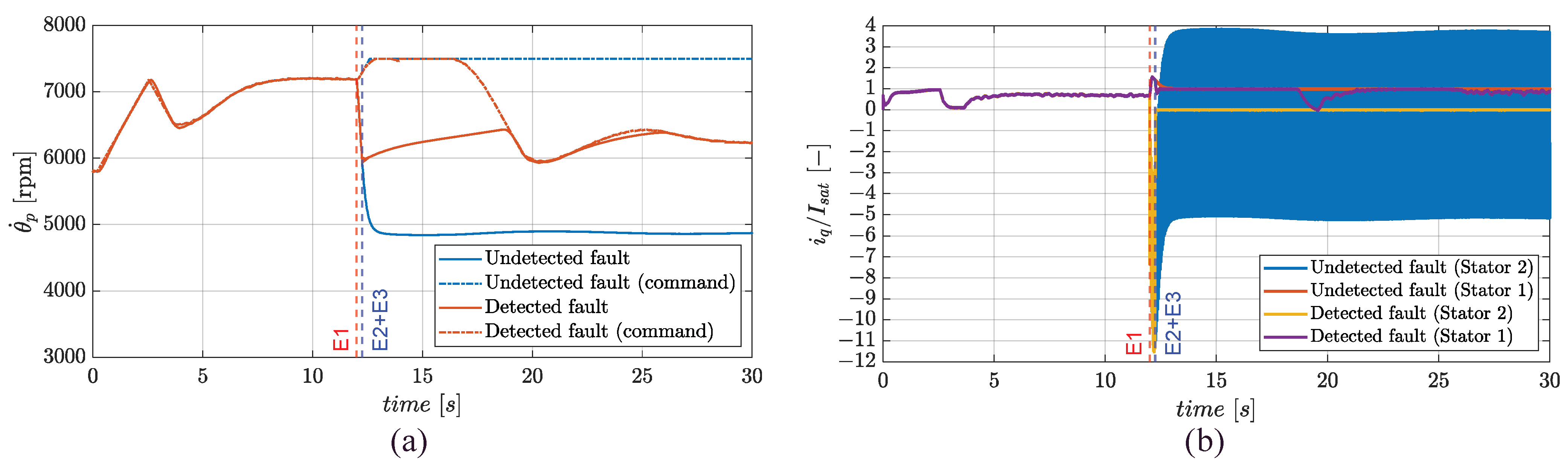
The propeller speed is plotted in Figure 10a. In case of undetected fault, the faulty stator brakes down the propeller, by reducing the speed up to about 1000 rpm below the cruise value (5800 rpm), thus resulting in negative RoC, Figure 9a. If the health-monitoring is applied, immediately after the compensation, the output of the SAS block (Figure 8) increases because of the airspeed reduction, Figure 9b, as well as for the diminishing output from the RoC regulator, thus causing an initial increase in the motor demand speed (up to about t = 16 s). During this transient period (from 12.25 s to 16 s), the healthy stator operates in saturation condition, as confirmed by the quadrature current output in Figure 10b. It can be also observed that the phase-to-ground fault introduces relevant ripples of current (hence torque) at about 800 Hz frequency, which is twice the motor electrical frequency (). The current peaks reach five times the maximum value for continuous duty cycle operations (), with a mean value of about −, which produces a braking torque contribution, Figure 10b.
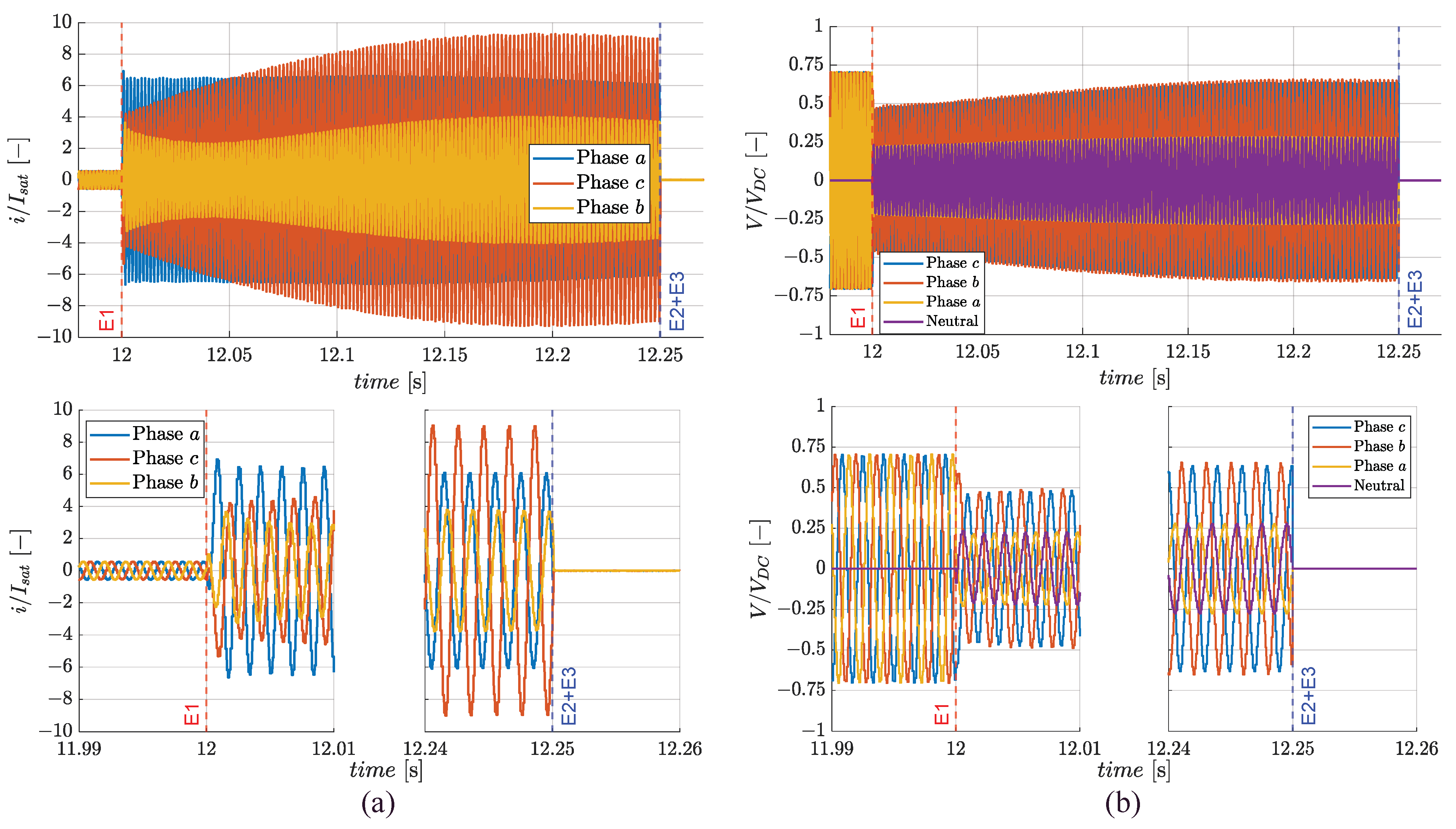
In Figure 11, the phase currents and voltages of the two stators for the compensated case are finally shown. The results are also proposed in the time range between the fault injection and compensation to emphasize the detailed dynamic behaviours: differently from the normal operation, the phase currents in the faulty stator (although still balanced, i.e., their sum is null) are not symmetric, Figure 11a. In fact, the current in phase c roughly push-pulls with reference to the one in phase a, while in the phase b the current progressively shifts to be roughly synchronous with it. The loss of current symmetry results from the voltage grounding on pin a (Figure 11b), which implies that the phase a voltage is driven by the neutral point voltage only. As a consequence of the symmetry loss, the Clarke—Park transform on stator 2 is no longer effective, and the direct and quadrature current demands () become harmonic quantities, Figure 10b.
3.3. Failure Transients in Cruise
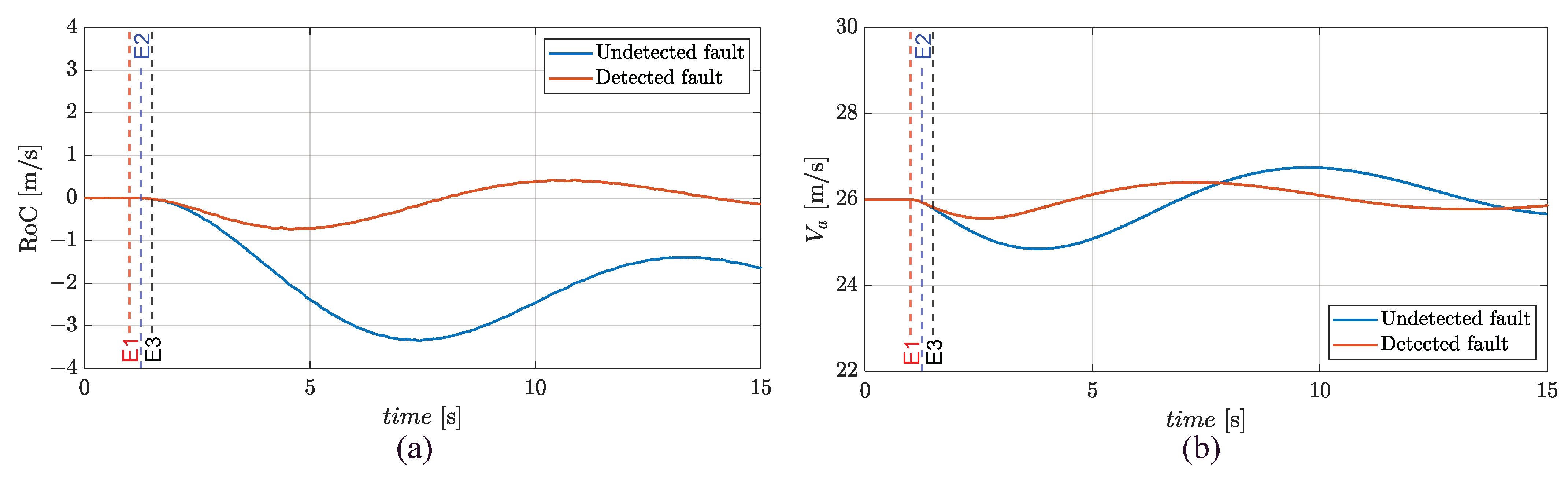
The simulations can be described with reference to Figure 12: for both simulations, E1 is imposed while the UAV is in steady cruise (t = 1 s); while in one of them, the fault is firstly detected (E2, at t = 1.25 s) and then compensated (E3, at t = 1.5 s), so that the CON modules are switched to operate from HSB/FMM to FMM/CSB.
Since in cruise the FEPS operates with one stator only, the undetected fault drastically impacts on UAV response, with the RoC that settles to about −2 m/s, Figure 12a. On the other hand, in the compensated case, the performances are fully restored. In both cases, the airspeed oscillates around the cruise value with the phugoid period, and a maximum deviation of about 1 m/s is observed, Figure 12b.
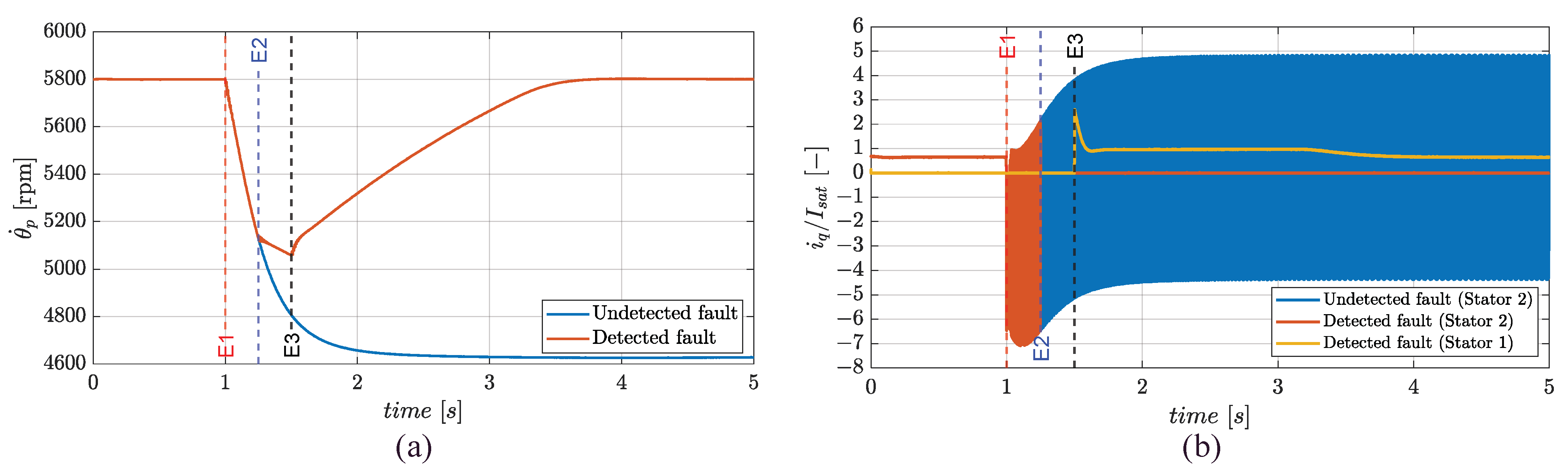
The propeller speed is plotted in Figure 13a. In the undetected case, the faulty stator brakes down the motor, reducing the speed up to about 1200 rpm below the cruise value (5800 rpm), justifying the negative RoC in Figure 12a. If the health-monitoring is applied, the delay time required for the full electric supply of the stand-by stator (from t = 1.25 s to t = 1.5 s) implies that resistive aerodynamic loads are applied to the propeller, and the speed rate diminishes, so that, immediately after the fault, the faulty stator acts as a brake.
The above discussion is further enforced by observing the response in terms of quadrature currents, Figure 13b. As also highlighted in Section 3.2, the phase-to-ground fault introduces high-frequency ripples, and, immediately after the fault, the mean value of the quadrature current is negative. On the other hand, in steady condition, it becomes positive (0.25 ), so that the faulty stator delivers power to the propeller.
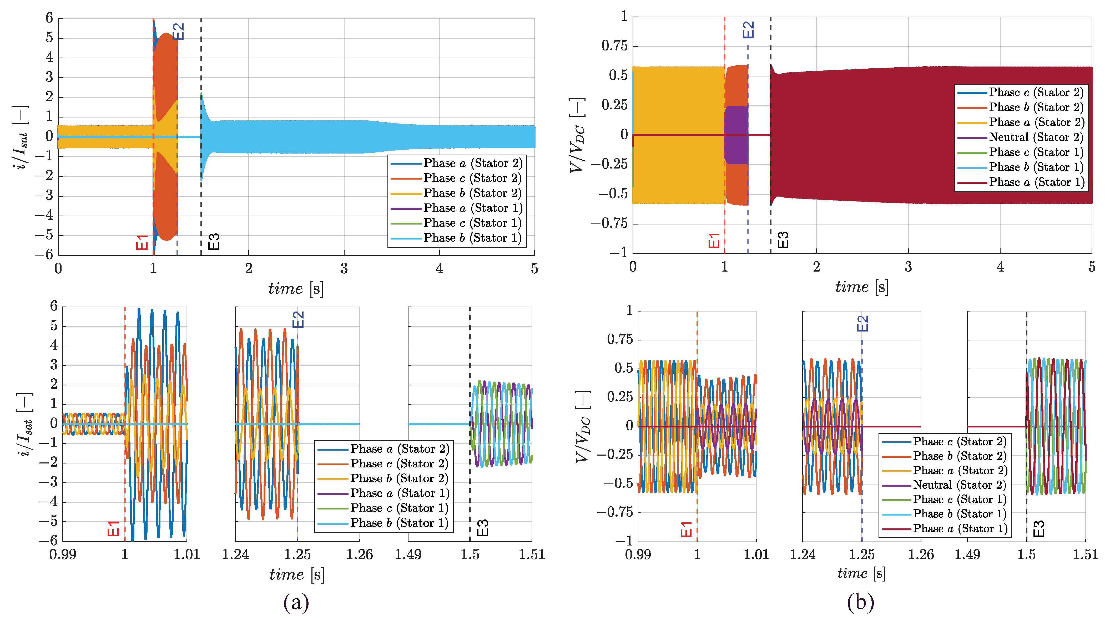
Finally, in Figure 14, the phase currents and voltages of the two stators for the compensated case are shown. The results are also proposed in the time range between the fault injection and compensation to emphasize out the detailed dynamic behaviours. The full electric activation of the stator 1 (at t = 1.5 s) is characterized by relevant peaks of the phase currents (Figure 14a), up to reach about three times the maximum value in continuous duty cycle operations (). As discussed in Section 3.2, the phase-to-ground fault causes the loss of the currents symmetry while maintaining their balance, Figure 14b.
3.4. Failure Transient and Transition from FMM to FTM in Flight Termination/Landing
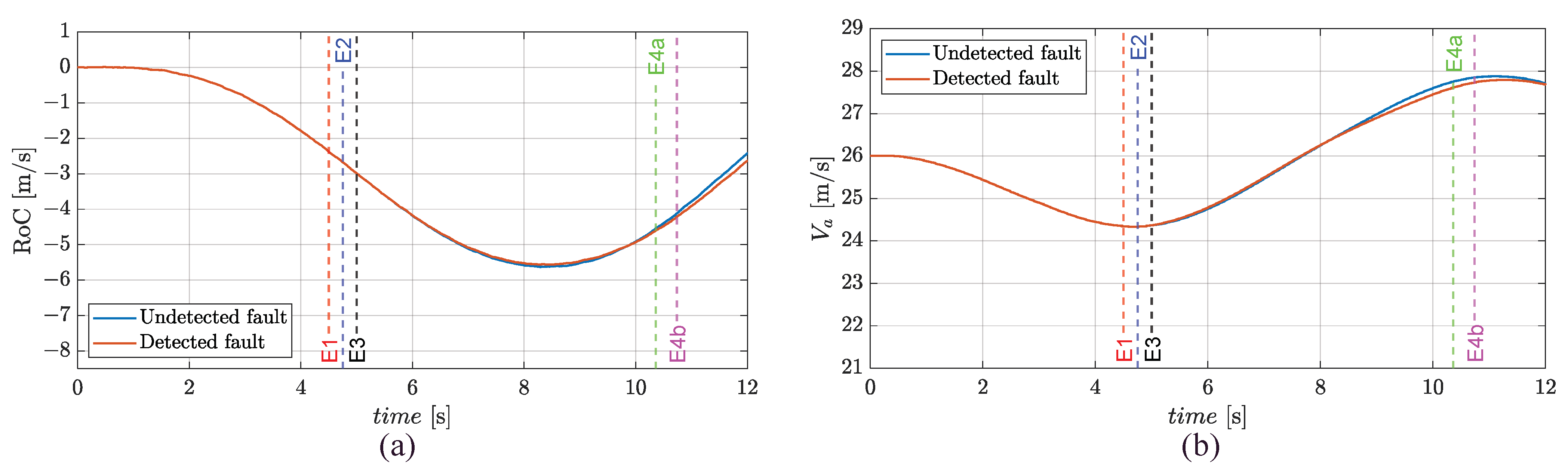
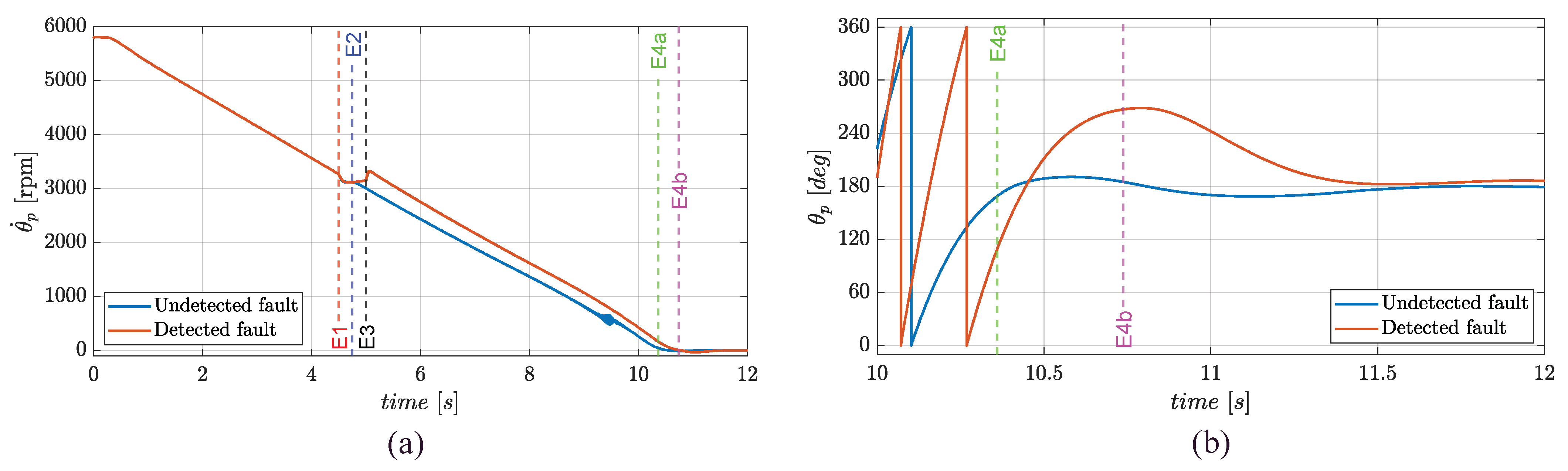
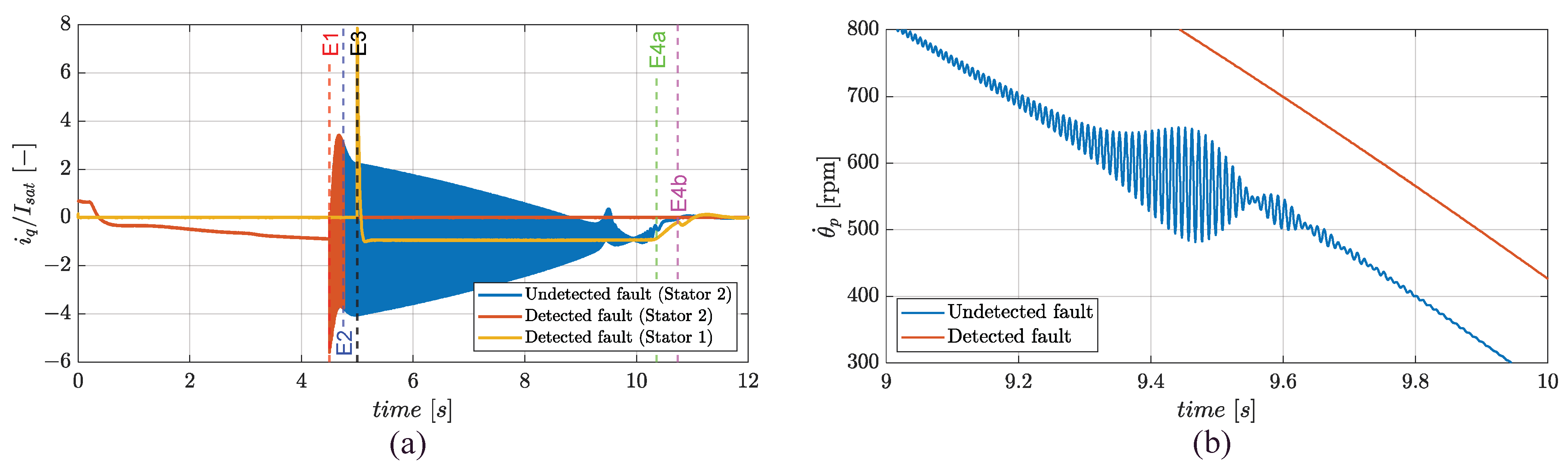
The simulations can be described with reference to Figure 15: for both simulations, E1 is imposed while the UAV is performing a steady descent motion (t = 4.5 s); while in one of the two ones, the fault is firstly detected (E2, at t = 4.75 s) and then compensated (E3, at t = 5 s), so that the CON modules switch from HSB/FMM to FMM/CSB. Successively, when the speed is adequately small (<1 rad/s), the CON modules switch from HSB/FMM to HSB/FTM in the undetected case (E4a, at t = 10.4 s), and from FMM/CSB to FTM/CSB if the health-monitoring is applied (E4b, at t = 10.7 s).
The UAV behaviour can be interpreted via Equation (12): since the elevator deflection maintains the pitch equilibrium, a reduction in the propeller speed implies a thrust reduction, which causes an oscillatory descendant trajectory, Figure 15a. On the other hand, the airspeed oscillates by following the phugoid behaviour, while keeping its mean value roughly to the one before the fault, Figure 15b.
The closed-loop tracking on propeller speed and position are reported in Figure 16. It is worth noting that the mode transition is executed when the speed is not zeroed yet, to anticipate the parachute opening, and that in both cases the position tracking to the predefined setpoint (180 deg) is correctly accomplished. The quadrature currents response (Figure 17a) also points out that, compared with the climb and cruise simulations, the failure transient for the undetected case impacts on the mechanical transmission too, because the electrical frequency sweeps down, up to equalling the drivetrain resonant frequency (located at 100 Hz), Figure 17b.
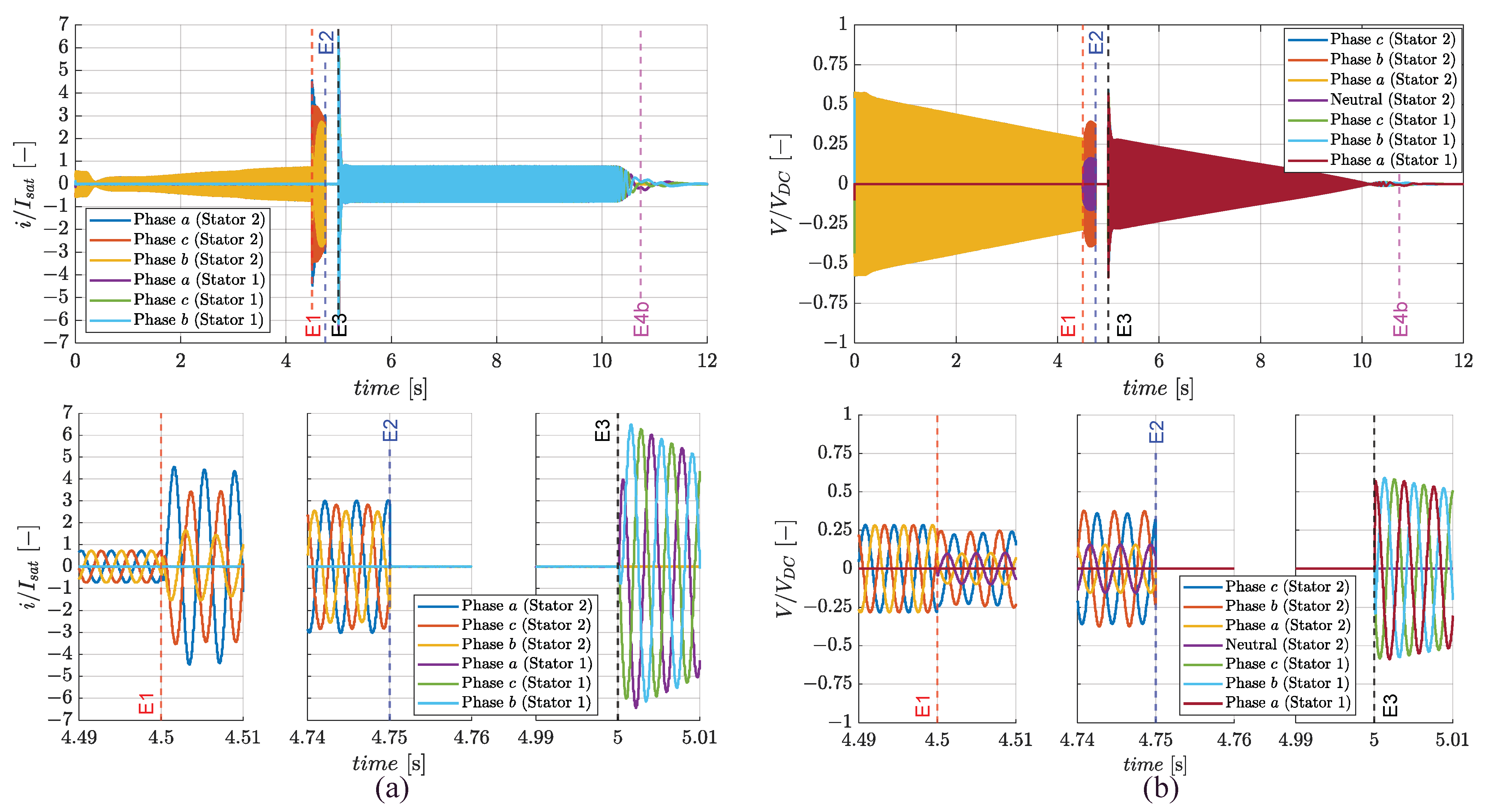
In Figure 18, the phase currents and voltages of the two stators for the compensated case are finally reported. The full electric activation of the stator 1 (at t = 5 s) is characterized by relevant peaks of the phase currents (Figure 18a), reaching up to about seven times the maximum value for continuous duty cycle (), while the stator 1 currents operate in saturation () until the propeller stops (at t = 10 s). Similarly to what was discussed in Section 3.2 and Section 3.3, the phase-to-ground fault again causes the loss of the currents’ symmetry while maintaining their balance (Figure 18a). Finally, it is worth noting that the reduction in voltage amplitudes is coherent with the reduction in the back-electromotive forces caused by the speed decrease (the homopolar voltage component is also represented in Figure 18b).
4. Discussion
As confirmed by the results in Section 3, the phase-to-ground fault can determine damages to different parts of the electric machine. In fact, to compensate for the voltage supply lack on the faulty phase, the currents in other phases strongly increase, leading to extremely hot temperatures with consequent deterioration of the magnets. Partial or complete demagnetization may occur, since the magnet coercivity decreases with temperature. Furthermore, another contribution to demagnetization derives from the flux weakening caused by the direct current increase. The direct current in the faulty stator is characterized by high-amplitude oscillations, so the flux linkage on the quadrature axis () can even overcome the magnet coercivity.
Furthermore, the phase-to-ground fault can also impact the structural integrity of system drivetrain (e.g., bearings). In fact, the symmetry loss of the faulty stator currents implies that the magnetic fields generated via the FOC technique are not synchronous with the rotor magnet’s motion. The ripple manifests at twice the electrical frequency and potential criticalities can arise if this frequency equals the structural resonance of the drivetrain.
The failure transient’s analysis proposed in Section 3 highlights that the phase-to-ground fault can strongly impact performances at the UAV level too. If the fault is not detected, the propeller torque reduces to below the one required for level flight, thus causing the UAV to fall. Furthermore, if one compares the failure transient in climb with the one in cruise, it is worth noting that the larger the speed demand for the faulty stator, the lower its torque output. During climb, the demand after the fault settles at the maximum value (7500 rpm, Figure 10a) and the mean torque to a negative value (Figure 10b); while in cruise, when the speed setpoint is kept at 5800 rpm (Figure 13a), the mean torque settles to a positive value (Figure 13b). Concerning the flight termination/landing, it is demonstrated that, even without fault detection, the FEPS is capable of stopping and aligning the propeller blades with the wing, even if the electrical frequency sweep related to the motor slowdown can generate potentially dangerous vibrations when the drivetrain resonant frequency is intercepted.
The future developments of the research will be focused on:
- System modelling validation, in particular:
- ○
- AFPMSM model, via experimental testing with reference to normal operation (failure transient characterisation will be always simulated, but using updated parameters);
- ○
- Propeller loads model, via CFD simulations, with special focus on the region of AR > 0.65 (no data from manufacturer);
- ○
- Mechanical drivetrain model, via experimental testing;
- ○
- UAV longitudinal dynamics, via flight data.
- System modelling enhancement, by including a thermal model of the motor that would permit assessing the effects of overcurrents caused by phase-to-ground fault, which are expected to determine severe overheating;
- Control system implementation in the ECU boards, via automatic MATLAB compilers for the “real-time” execution at a 10 kHz sampling rate.
5. Conclusions
The fault-tolerant control of the FEPS employed by the lightweight fixed-wing UAV named TERSA has been designed and verified in terms of dynamic performances by simulating major electrical faults during relevant flight manoeuvres. The reference FEPS includes a dual-stator AFPMSM operating in active/active mode during climb and in stand-by/active mode in other flight phases, and it is designed as a finite-state machine to switch the closed-loop system from speed-tracking control during the flight, to position-tracking control during flight termination/landing, when the propeller blades are aligned with the wings to avoid interference with the landing parachute opening. Thanks to a high-fidelity modelling approach, the impacts of failure transients from component levels up to UAV levels during climb, cruise and flight termination/landing manoeuvres are evaluated, by simulating a phase-to-ground fault on a phase of one of the two AFPMSM stators. The results show that if the fault is not detected, it strongly impacts on both FEPS and UAV performances, up to causing the UAV to fall, the generation of large-amplitude high-frequency torque and current oscillations, and dangerous interactions with the drivetrain structural resonance. On the other hand, if the health monitoring is applied and the fault is detected and compensated, the FEPS permits maintaining the climb capability (even if it is with reduced performance), holding the UAV altitude and speed during cruise, as well as safely managing the flight termination/landing manoeuvre.
Author Contributions
Conceptualization, methodology and investigation, A.S. and G.D.R.; software, data curation and writing—original draft preparation, A.S.; validation, formal analysis and writing—review and editing, G.D.R.; resources, supervision and visualization, G.D.R. and R.G.; project administration and funding acquisition, R.G. All authors have read and agreed to the published version of the manuscript.
Funding
This research was co-funded by the Italian Government (Ministero Italiano dello Sviluppo Economico, MISE) and by the Tuscany Regional Government, in the context of the R&D project “Tecnologie Elettriche e Radar per SAPR Autonomi (TERSA)”, Grant number: F/130088/01-05/X38.
Institutional Review Board Statement
Not applicable.
Informed Consent Statement
Not applicable.
Data Availability Statement
Not applicable.
Acknowledgments
The authors wish to thank Luca Sani, from the University of Pisa (Dipartimento di Ingegneria dell’Energia, dei Sistemi, del Territorio e delle Costruzioni), for the support in the definition of the AFPMSM model parameters, and Ing. Francesco Schettini, from Sky Eye Systems (Italy), for the information about the aero-mechanical data and the general performances of the UAV.
Conflicts of Interest
The authors declare no conflict of interest.
Appendix A
This section contains tables reporting parameters and data related to the propulsion system model (Table A1) and the UAV model (Table A2).

Table A1.
FEPS model parameters.
| Definition | Symbol | Value | Unit |
|---|---|---|---|
| Stator phase resistance | R | 0.025 | Ω |
| Stator phase inductance single module | L | 2 × 10⁻⁵ | H |
| Pole pairs number | nd | 5 | - |
| Torque constant (single stator) | kt | 0.06 | Nm/Arms |
| Back-electromotive force constant | ke | 0.018 | V/(rad/s) |
| Permanent magnet flux linkage | λm | 0.008 | Wb |
| Maximum current (continuous duty cycle) | Isat | 46 | Arms |
| Voltage supply | VDC | 36 | V |
| Rotor inertia | Jem | 8.2 × 10⁻³ | kg·m2 |
| Propeller diameter | Dp | 0.5588 | m |
| Propeller inertia | Jp | 1.62 × 10⁻² | kg·m2 |
| Joint stiffness | Kgb | 1.598 × 10³ | Nm/rad |
| Joint damping | Cgb | 0.2545 | Nm/(rad/s) |
Table A2.
UAV model parameters.
| Definition | Symbol | Value | Unit |
|---|---|---|---|
| UAV mass | 35 | kg | |
| Air density | ISA model | kg/m3 | |
| Reference wing area | 1.058 | m2 | |
| Mean aerodynamic chord | 0.303 | m | |
| Lift–slope coefficient due to AoA | 5.74 | 1/rad | |
| Lift–slope coefficient due to elevator deflection | 0.56 | 1/rad | |
| Pitch moment-slope coefficient due to AoA | , | −1.1 | 1/rad |
| Pitch moment-slope coefficient due to elevator deflection | −2.4 | 1/rad | |
| Zero-lift pitch moment coefficient | 0.36 | - | |
| Zero-lift angle | 3.5 | deg | |
| Zero-lift drag coefficient | 0.0491 | - | |
| Induced drag factor | k | 0.0462 | - |
Table A3.
FEPS and UAV regulators parameters.
| Definition | Symbol | Value | Unit |
|---|---|---|---|
| Proportional gain of current regulator | 4 × 10⁻⁴ | V/A | |
| Integral gain of current regulator | 0.8 | V/A/s | |
| Anti-windup gain of current regulator | 3140 | A/V | |
| Saturation limit of current regulator | 32 | V | |
| Proportional gain of speed regulator | 5 | A s/rad | |
| Integral gain of speed regulator | 15 | A/rad | |
| Anti-windup gain of speed regulator | 314 | A rad/s | |
| Saturation limit of speed regulator | 46 | Arms | |
| Proportional gain of rotation regulator | 1.9 | 1/s | |
| Integral gain of rotation regulator | 0.19 | 1/s2 | |
| Anti-windup gain of rotation regulator | 31.4 | s | |
| Saturation limit of rotation regulator | 785 | rad/s | |
| Proportional gain of RoC regulator | 65.6 | rad/m | |
| Integral gain of RoC regulator | 1.6 | rad s/m | |
| Anti-windup gain of RoC regulator | 10 | m/rad | |
| RoC-loop SAS gain | 100 | rad/m | |
| FEPS sample time | 10−4 | s | |
| FCC sample time | 10−3 | s |
References
- Unmanned Aerial Vehicle (UAV) Market by Point of Sale, Systems, Platform (Civil & Commercial, and Defense & Government), Function, End Use, Application, Type, Mode of Operation, MTOW, Range, and Region—Global Forecast to 2026. Research and Markets: Northbrook, IL, USA. 2021. Available online: https://www.marketsandmarkets.com/Market-Reports/unmanned-aerial-vehicles-uav-market-662.html?gclid=CjwKCAjwrqqSBhBbEiwAlQeqGiTZXREsmSFhSPuOaugcttjxTwo4L3KX7xYtWCycLbFVNWB6YuJIDhoC7ksQAvD_BwE (accessed on 4 April 2022).
- Schlachter, F. Has the Battery Bubble Burst? Am. Phys. Soc. 2012, 21, 8. Available online: https://www.aps.org/publications/apsnews/201208/backpage.cfm (accessed on 2 April 2022).
- Suti, A.; Di Rito, G.; Galatolo, R. Climbing performance enhancement of small fixed-wing UAVs via hybrid electric propulsion. In Proceedings of the 2021 IEEE Workshop on Electrical Machines Design, Control and Diagnosis (WEMDCD), Modena, Italy, 8–9 April 2021. [Google Scholar] [CrossRef]
- Power, Electric Motor Market. Fortune Business Insights. Available online: https://www.fortunebusinessinsights.com/industry-reports/electric-motor-market-100752 (accessed on 4 April 2022).
- Dipartimento di Ingegneria Civile e Industriale, Progetti istituzionali. TERSA (Tecnologie Elettriche e Radar per Sistemi aeromobili a pilotaggio remoto Autonomi). Available online: https://dici.unipi.it/ricerca/progetti-finanziati/tersa/ (accessed on 7 April 2022).
- Mamen, A.; Supatti, U. A survey of hybrid energy storage systems applied for intermittent renewable energy systems. In Proceedings of the 2017 14th International Conference on Electrical Engineering/Electronics, Computer, Telecommunications and Information Technology (ECTI-CON), Phuket, Thailand, 27–30 June 2017. [Google Scholar] [CrossRef]
- Cao, W.; Mecrow, B.; Atkinson, G.; Bennett, J.; Atkinson, D. Overview of Electric Motor Technologies Used for More Electric Aircraft (MEA). IEEE Trans. Ind. Electron. 2012, 59, 3523–3531. [Google Scholar] [CrossRef]
- Suti, A.; Di Rito, G.; Galatolo, R. Fault-Tolerant Control of a Three-Phase Permanent Magnet Synchronous Motor for Lightweight UAV Propellers via Central Point Drive. Actuators 2021, 10, 253. [Google Scholar] [CrossRef]
- NATO Standardization Agency. STANAG 4671—Standardization Agreement—Unmanned Aerial Vehicles Systems Airworthiness Requirements (USAR); NATO Standardization Agency (STANAG): Brussels, Belgium, 2009. [Google Scholar]
- Ryu, H.M.; Kim, J.W.; Sul, S.K. Synchronous-frame current control of multiphase synchronous motor under asymmetric fault condition due to open phases. IEEE Trans. Ind. Appl. 2006, 42, 1062–1070. [Google Scholar] [CrossRef]
- Liu, G.; Lin, Z.; Zhao, W.; Chen, Q.; Xu, G. Third Harmonic Current Injection in Fault-Tolerant Five-Phase Permanent-Magnet Motor Drive. IEEE Trans. Power Electron. 2018, 33, 6970–6979. [Google Scholar] [CrossRef]
- Bennet, J.; Mecrow, B.; Atkinson, D.; Atkinson, G. Safety-critical design of electromechanical actuation systems in commercial aircraft. IET Electr. Power Appl. 2011, 5, 37–47. [Google Scholar] [CrossRef]
- Mazzoleni, M.; Di Rito, G.; Previdi, F. Fault Diagnosis and Condition Monitoring Approaches. In Electro-Mechanical Actuators for the More Electric Aircraft; Springer: Cham, Switzerland, 2021; pp. 87–117. [Google Scholar]
- De Rossiter Correa, M.; Jacobina, C.; Da Silva, E.; Lima, A. An induction motor drive system with improved fault tolerance. IEEE Trans. Ind. Appl. 2001, 37, 873–879. [Google Scholar] [CrossRef]
- Ribeiro, R.; Jacobina, C.; Lima, A.; da Silva, E. A strategy for improving reliability of motor drive systems using a four-leg three-phase converter. In Proceedings of the APEC 2001, Sixteenth Annual IEEE Applied Power Electronics Conference and Exposition (Cat. No. 01CH37181), Anaheim, CA, USA, 4–8 March 2001. [Google Scholar] [CrossRef]
- Zhang, R.; Prasad, V.H.; Boroyevich, D.; Lee, F.J. Three-Dimensional Space Vector Modulation for Four-Leg Voltage-Cource Converter. IEEE Trans. Power Electron. 2002, 17, 314–326. [Google Scholar] [CrossRef]
- Kontarcek, A.; Bajec, P.; Nemec, M.; Ambrožic, V.; Nedeljkovic, D. Cost-Effective Three-Phase PMSM Drive Tolerant to Open-Phase Fault. IEEE Trans. Ind. Electron. 2015, 62, 6708–6718. [Google Scholar] [CrossRef]
- Bonnet, A.; Soukup, G. Cause and analysis of stator and rotor failures in three-phase squirrel-cage induction motors. IEEE Trans. Ind. Appl. 1992, 28, 921–937. [Google Scholar] [CrossRef]
- Khalaief, A.; Boussank, M.; Gossa, M. Open phase faults detection in PMSM drives based on current signature analysis. In Proceedings of the XIX International Conference on Electrical Machines (ICEM 2010), Roma, Italy, 6–8 September 2010. [Google Scholar] [CrossRef]
- Li, W.; Tang, H.; Luo, S.; Yan, X.; Wu, Z. Comparative analysis of the operating performance, magnetic field, and temperature rise of the three-phase permanent magnet synchronous motor with or without fault-tolerant control under single-phase open-circuit fault. IET Electr. Power Appl. 2021, 15, 861–872. [Google Scholar] [CrossRef]
- Zhou, X.; Sun, J.; Li, H.; Song, X. High Performance Three-Phase PMSM Open-Phase Fault-Tolerant Method Based on Reference Frame Transformation. IEEE Trans. Ind. Electron. 2019, 66, 7571–7580. [Google Scholar] [CrossRef]
- Faiz, J.; Nejadi-Koti, H.; Valipour, Z. Comprehensive review on inter-turn fault indexes in permanent magnet motors. IET Electr. Power Appl. 2017, 11, 142–156. [Google Scholar] [CrossRef]
- Krzysztofiak, M.; Skowron, M.; Orlowska-Kowalska, T. Analysis of the Impact of Stator Inter-Turn Short Circuits on PMSM Drive with Scalar and Vector Control. Energies 2021, 14, 153. [Google Scholar] [CrossRef]
- Arabaci, H.; Bilgin, O. The Detection of Rotor Faults By Using Short Time Fourier Transform. In Proceedings of the 2007 IEEE 15th Signal Processing and Communications Applications, Eskisehir, Turkey, 11–13 June 2007. [Google Scholar] [CrossRef]
- Mohammed, O.A.; Liu, Z.; Liu, S.; Abed, N.Y. Internal Short Circuit Fault Diagnosis for PM Machines Using FE-Based Phase Variable Model and Wavelets Analysis. IEEE Trans. Magn. 2007, 43, 1729–1732. [Google Scholar] [CrossRef]
- Baggu, M.M.; Chowdhury, B.H. Implementation of a Converter in Sequence Domain to Counter Voltage Imbalances. In Proceedings of the 2007 IEEE Power Engineering Society General Meeting, Tampa, FL, USA, 24–28 June 2007. [Google Scholar] [CrossRef]
- Blánquez, F.R.; Aranda, M.; Rebollo, E.; Blázquez, F.; Platero, C.A. New Fault-Resistance Estimation Algorithm for Rotor-Winding Ground-Fault Online Location in Synchronous Machines With Static Excitation. IEEE Trans. Ind. Electron. 2015, 62, 1901–1911. [Google Scholar] [CrossRef] [Green Version]
- Tan, R.H.; Ramachandaramurthy, V.K. A Comprehensive Modeling and Simulation of Power Quality Disturbances Using MATLAB/SIMULINK. In Power Quality Issues in Distributed Generation; Luszcz, J., Ed.; IntechOpen: London, UK, 2015. [Google Scholar] [CrossRef] [Green Version]
- Pietrzak, P.; Wolkiewicz, M. On-line Detection and Classification of PMSM Stator Winding Faults Based on Stator Current Symmetrical Components Analysis and the KNN Algorithm. Electronics 2021, 10, 1786. [Google Scholar] [CrossRef]
- Fourlas, G.K.; Karras, G.C. A Survey on Fault Diagnosis and Fault-Tolerant Control Methods for Unmanned Aerial Vehicles. Machines 2021, 9, 197. [Google Scholar] [CrossRef]
- Freeman, P.; Pandita, R.; Srivastava, N.; Balas, G.J. Model-Based and Data-Driven Fault Detection Performance for Small UAV. IEEE/ASME Trans. Mechatron. 2013, 18, 1300–1309. [Google Scholar] [CrossRef]
- Odendaal, H.M.; Jones, T. Actuator fault detection and isolation: An optimised parity space approach. Control. Eng. Pract. 2014, 26, 222–232. [Google Scholar] [CrossRef]
- Cao, D.; Fu, J.; Li, Y. Fault diagnosis of actuator of Flight Control System based on analytic model (IEEE CGNCC). In Proceedings of the 2016 IEEE Chinese Guidance, Navigation and Control Conference (CGNCC), Nanjing, China, 12–14 August 2016. [Google Scholar] [CrossRef]
- Abbaspour, A.; Yen, K.k.; Forouzannezhad, P.; Sargolzaei, A. A Neural Adaptive Approach for Active Fault-Tolerant Control Design in UAV. IEEE Trans. Syst. Man Cybern. Syst. 2020, 50, 3401–3411. [Google Scholar] [CrossRef]
- Yin, L.; Liu, J.; Yang, P. Interval Observer-based Fault Detection for UAVs Formation with Actuator Faults. In Proceedings of the 2019 CAA Symposium on Fault Detection, Supervision and Safety for Technical Processes (SAFEPROCESS), Xiamen, China, 5–7 July 2019. [Google Scholar] [CrossRef]
- Li, D.; Yang, P.; Liu, Z.; Liu, J. Fault Diagnosis for Distributed UAVs Formation Based on Unknown Input Observer. In Proceedings of the 2019 Chinese Control Conference (CCC), Guangzhou, China, 27–30 July 2019. [Google Scholar] [CrossRef]
- Yu, Z.; Liu, Z.; Zhang, Y.; Qu, Y.; Su, C.Y. Distributed Finite-Time Fault-Tolerant Containment Control for Multiple Unmanned Aerial Vehicles. IEEE Trans. Neural Netw. Learn. Syst. 2020, 31, 2077–2091. [Google Scholar] [CrossRef]
- Zogopoulos-Papaliakos, G.; Karras, G.C.; Kyriakopoulos, K.J. A Fault-Tolerant Control Scheme for Fixed-Wing UAVs with Flight Envelope Awareness. J. Intell. Robot. Syst. 2021, 102, 46. [Google Scholar] [CrossRef]
- Haaland, O.M.; Wenz, A.W.; Gryte, K.; Hann, R.; Johansen, T.A. Detection and Isolation of Propeller Icing and Electric Propulsion System Faults in Fixed-Wing UAVs. In Proceedings of the 2021 International Conference on Unmanned Aircraft Systems (ICUAS), Athens, Greece, 15–18 June 2021. [Google Scholar] [CrossRef]
- Huang, R.; Liu, C.; Song, Z.; Zhao, H. Design and Analysis of a Novel Axial-Radial Flux Permanent Magnet Machine with Halbach-Array Permanent Magnets. Energies 2021, 14, 3639. [Google Scholar] [CrossRef]
- Mahmoudi, A.; Rahim, N.A.; Hew, W.P. Axial-flux permanent-magnet machine modeling, design, simulation and analysis. Sci. Res. Essays 2011, 6, 2525–2549. [Google Scholar] [CrossRef]
- Zhao, J.; Han, Q.; Dai, Y.; Hua, M. Study on the Electromagnetic Design and Analysis of Axial Flux Permanent Magnet Synchronous Motors for Electric Vehicles. Energies 2019, 12, 3451. [Google Scholar] [CrossRef] [Green Version]
- Kahourzade, S.; Mahmoudi, A.; Ping, H.W.; Mahmoudi, N.U. A Comprehensive Review of Axial-Flux Permanent-Magnet Machines. Can. J. Electr. Comput. Eng. 2014, 37, 19–33. [Google Scholar] [CrossRef]
- Wang, Z.; Chen, J.; Cheng, M. Fault tolerant control of double-stator-winding PMSM for open phase operation based on asymmetric current injection. In Proceedings of the 17th International Conference on Electrical Machines and Systems (ICEMS), Hangzhou, China, 22–25 October 2014. [Google Scholar] [CrossRef]
- APC Propellers TECHNICAL INFO. Available online: https://www.apcprop.com/technical-information/performance-data/ (accessed on 2 May 2021).
- Gong, A.; Verstraete, D. Evaluation of a hybrid fuel-cell based propulsion system with a hardware-in-the-loop flight simulator. In Proceedings of the ISABE, Manchester, UK, 3–8 September 2017; Available online: https://www.researchgate.net/publication/320998946_Evaluation_of_a_hybrid_fuel-cell_based_propulsion_system_with_a_hardware-in-the-loop_flight_simulator (accessed on 28 March 2022).
- Pivano, L.; Smogeli, O.N.; Fossen, T.I.; Johansen, T.A. Experimental Validation of a marine propeller thrust estimation scheme. Nor. Soc. Autom. Control 2007, 28, 105–112. [Google Scholar] [CrossRef] [Green Version]
- Darba, A.; Esmalifalak, M.; Barazandeh, E.S. Implementing SVPWM technique to axial flux permanent magnet synchronous motor drive with internal model current controller. In Proceedings of the 2010 4th International Power Engineering and Optimization Conference (PEOCO), Shah Alam, Malaysia, 23–24 June 2010. [Google Scholar] [CrossRef] [Green Version]
- Sabah, N.; Humod, A.T.; Hasan, F.A. Field Oriented Control of the Axial Flux PMSM Based On Multi-Objective Particle Swarm Optimization. Technol. Rep. Kansai Univ. 2020, 62, 1493. Available online: https://www.kansaiuniversityreports.com/article/field-oriented-control-of-the-axial-flux-pmsm-based-on-multi-objective-particle-swarm-optimization (accessed on 1 April 2022).
- Rosario-Gabriel, I.; Cortés, R.H. Aircraft Longitudinal Control based on the Lanchester’s Phugoid Dynamics Model. In Proceedings of the 2018 International Conference on Unmanned Aircraft Systems (ICUAS), Dallas, TX, USA, 12–15 June 2018. [Google Scholar] [CrossRef]
- Lanchester, F.W. Aerial Flight: Part 2, Aerodonetics; A Constable: London, UK, 1908. [Google Scholar]
Figure 1.
Rendering of the TERSA UAV [5].
Figure 1.
Rendering of the TERSA UAV [5].

Figure 2.
Schematics of the FEPS architecture.

Figure 3.
Flow chart defining FEPS operation modes.

Figure 4.
FEPS: (a) mechanical scheme; (b) equivalent three-phase PMSM scheme (one pole pair).

Figure 5.
APC 22 × 10E propeller curves: thrust coefficient (a) and torque coefficient (b), thrust (c) and torque (d) at sea level.
Figure 5.
APC 22 × 10E propeller curves: thrust coefficient (a) and torque coefficient (b), thrust (c) and torque (d) at sea level.

Figure 6.
FEPS closed-loop architecture.

Figure 7.
Reference schematics for the UAV longitudinal phugoid dynamics.

Figure 8.
Rate-of-climb closed-loop system.

Figure 9.
UAV response in climb with phase-to-ground fault on stator 2 (E1, E2 and E3 defined in Section 3.1): RoC (a), airspeed (b).
Figure 9.
UAV response in climb with phase-to-ground fault on stator 2 (E1, E2 and E3 defined in Section 3.1): RoC (a), airspeed (b).

Figure 10.
FEPS response in climb with phase-to-ground fault on stator 2 (E1, E2 and E3 defined in Section 3.1): propeller speed (a), quadrature current (b), with .
Figure 10.
FEPS response in climb with phase-to-ground fault on stator 2 (E1, E2 and E3 defined in Section 3.1): propeller speed (a), quadrature current (b), with .

Figure 11.
FEPS currents and voltages responses in climb with phase-to-ground fault on stator 2 (E1, E2 and E3 defined in Section 3.1): stator 2 currents (a) with ; stator 2 voltages (b) with .
Figure 11.
FEPS currents and voltages responses in climb with phase-to-ground fault on stator 2 (E1, E2 and E3 defined in Section 3.1): stator 2 currents (a) with ; stator 2 voltages (b) with .

Figure 12.
UAV response in cruise with phase-to-ground fault on stator 2 (E1, E2 and E3 defined in Section 3.1): RoC (a), airspeed (b).
Figure 12.
UAV response in cruise with phase-to-ground fault on stator 2 (E1, E2 and E3 defined in Section 3.1): RoC (a), airspeed (b).

Figure 13.
FEPS response in cruise with phase-to-ground fault on stator 2 (E1, E2 and E3 defined in Section 3.1): propeller speed (a), quadrature current (b), with .
Figure 13.
FEPS response in cruise with phase-to-ground fault on stator 2 (E1, E2 and E3 defined in Section 3.1): propeller speed (a), quadrature current (b), with .

Figure 14.
FEPS currents and voltages responses in cruise with phase-to-ground fault on stator 2 (E1, E2 and E3 defined in Section 3.1): stator 2 currents (a) with ; stator 2 voltages (b) with .
Figure 14.
FEPS currents and voltages responses in cruise with phase-to-ground fault on stator 2 (E1, E2 and E3 defined in Section 3.1): stator 2 currents (a) with ; stator 2 voltages (b) with .

Figure 15.
UAV response in flight termination/landing with phase-to-ground fault on stator 2 (E1, E2, E3 and E4 defined in Section 3.1): RoC (a), airspeed (b).
Figure 15.
UAV response in flight termination/landing with phase-to-ground fault on stator 2 (E1, E2, E3 and E4 defined in Section 3.1): RoC (a), airspeed (b).

Figure 16.
FEPS response in flight termination/landing with phase-to-ground fault on stator 2 (E1, E2, E3 and E4 defined in Section 3.1): propeller speed (a), propeller angle (b).
Figure 16.
FEPS response in flight termination/landing with phase-to-ground fault on stator 2 (E1, E2, E3 and E4 defined in Section 3.1): propeller speed (a), propeller angle (b).

Figure 17.
FEPS response in flight termination/landing with phase-to-ground fault on stator 2 (E1, E2, E3 and E4 defined in Section 3.1): quadrature currents (a) with , propeller speed (b).
Figure 17.
FEPS response in flight termination/landing with phase-to-ground fault on stator 2 (E1, E2, E3 and E4 defined in Section 3.1): quadrature currents (a) with , propeller speed (b).

Figure 18.
FEPS response in flight termination/landing with phase-to-ground fault on stator 2 (E1, E2, E3 and E4 defined in Section 3.1): stator 2 currents (a) with ; stator 2 voltages (b) with .
Figure 18.
FEPS response in flight termination/landing with phase-to-ground fault on stator 2 (E1, E2, E3 and E4 defined in Section 3.1): stator 2 currents (a) with ; stator 2 voltages (b) with .

Table 1.
FEPS operation modes as functions of mission phases and detected faults.
| Mission Phase | MON1 Fault Flag | MON2 Fault Flag | CON Mode (CON1/CON2) | FEPS Status (Stator 1/Stator 2) |
|---|---|---|---|---|
| Climb | off off on | off on off | FMM/FMM FMM/CSB CSB/FMM | Normal operation (active/active) Fail-operative (active/passive) Fail-operative (passive/active) |
| Cruise, Loiter, Descent | off off | off on | HSB/FMM FMM/CSB | Normal operation (stand-by/active) Fail-operative (active/passive) |
| Flight termination/Landing | off off | off on | HSB/FTM FTM/CSB | Normal operation (stand-by/active) Fail-operative (active/passive) |
Publisher’s Note: MDPI stays neutral with regard to jurisdictional claims in published maps and institutional affiliations. |
© 2022 by the authors. Licensee MDPI, Basel, Switzerland. This article is an open access article distributed under the terms and conditions of the Creative Commons Attribution (CC BY) license (https://creativecommons.org/licenses/by/4.0/).
Share and Cite
MDPI and ACS Style
Suti, A.; Di Rito, G.; Galatolo, R. Fault-Tolerant Control of a Dual-Stator PMSM for the Full-Electric Propulsion of a Lightweight Fixed-Wing UAV. Aerospace 2022, 9, 337. https://0-doi-org.brum.beds.ac.uk/10.3390/aerospace9070337
AMA Style
Suti A, Di Rito G, Galatolo R. Fault-Tolerant Control of a Dual-Stator PMSM for the Full-Electric Propulsion of a Lightweight Fixed-Wing UAV. Aerospace. 2022; 9(7):337. https://0-doi-org.brum.beds.ac.uk/10.3390/aerospace9070337
Chicago/Turabian StyleSuti, Aleksander, Gianpietro Di Rito, and Roberto Galatolo. 2022. "Fault-Tolerant Control of a Dual-Stator PMSM for the Full-Electric Propulsion of a Lightweight Fixed-Wing UAV" Aerospace 9, no. 7: 337. https://0-doi-org.brum.beds.ac.uk/10.3390/aerospace9070337
Note that from the first issue of 2016, this journal uses article numbers instead of page numbers. See further details here.