
Design of an Integrated Platform for Active Debris Removal

1
School of Xuteli, Beijing Institute of Technology, Beijing 100081, China
2
School of Aerospace Engineering, Beijing Institute of Technology, Beijing 100081, China
*
Author to whom correspondence should be addressed.
Aerospace 2022, 9(7), 339; https://0-doi-org.brum.beds.ac.uk/10.3390/aerospace9070339
Submission received: 29 May 2022
/
Revised: 19 June 2022
/
Accepted: 21 June 2022
/
Published: 25 June 2022
(This article belongs to the Special Issue Space Debris Removal: Challenges and Opportunities)
Abstract
:In research concerning active debris removal, scholars have proposed dozens of schemes for removing debris. However, every scheme has both advantages and disadvantages, and no scheme possesses an overwhelming advantage. This paper proposes an integrated platform scheme which integrates multiple capture and deorbit technologies, such as a tethered net, harpoon, and robotic arm, to improve the success rate in terms of the active removal of debris of different shapes and different sizes. The design of the mechanisms of the integrated platform is presented in detail.
1. Introduction
There are various types of space debris, such as defunct satellites, spent rocket bodies, spacecraft fragments, meteoroids, etc. Although the proposed methods for active debris removal (ADR) have their own advantages, they also have prominent shortcomings, and thus it is difficult for them to meet mission requirements in practice. In the capture phase, a robotic arm is only suitable for capturing non-spinning or slow-spinning targets of regular shapes and is unable to capture non-cooperative targets with a high spinning rate [1,2,3,4]; a tethered net is suitable for non-cooperative spinning targets and has been verified by experiments in a microgravity environment [5], but its technical maturity is too low, and the net closing mechanism is not reliable [6,7]; a harpoon can be used repeatedly, but it may generate more and more small debris during its collision with the target, and it may ricochet when the target is spinning or has a thick shell [8,9,10]. In the deorbit phase, a post-capture phase, passive deorbit methods such as drag sails not only have strict requirements in the space environment, but also have long-running operations [11,12]. Laser radiation, either from the ground or space, has the capability to remove tumbling debris, but the deorbit process is too time-consuming and difficult to control [13,14]. If different ADR methods are used in different missions for different types of debris, the cost can be tremendous, making engineering applications infeasible. Therefore, developing ADR methods for removing multiple debris of different shapes and sizes in a single mission are of great importance.
The integrated platform proposed in this paper integrates the three techniques, the tethered net, harpoon, and robotic arms. For any target, it can use a single technique for capture or use a combination of multiple techniques to improve the success rate. When multiple techniques work together, the harpoon is first used to pierce the target to achieve a preliminary capture. Then, the tethered net is ejected to capture and de-spin the target to establish a flexible connection. Finally, after the tether is retrieved and the target is de-spun, the robotic arms are used to grab the target to establish a firm connection. Obviously, the integrated platform has the advantages of wide applicability, a low cost, and high robustness.
2. Mechanism Design
The proposed system for ADR is composed of two parts, one of which is the orbiter, which is responsible for carrying and transportation, and the other is the integrated platform, which is responsible for capturing debris. The integrated platform is in fact a servicing satellite.
2.1. Orbiter
The orbiter (as shown in Figure 1) is composed of one or more transport modules, and the number of the modules can be increased according to mission requirements. Each module can carry 40 servicing satellites at once, and the modules are launched in a single rocket. When the orbiter arrives at and is inserted into its nominal orbit, it will eject the servicing satellites by using a passive device storing elastic potential energy.
2.2. Servicing Satellite
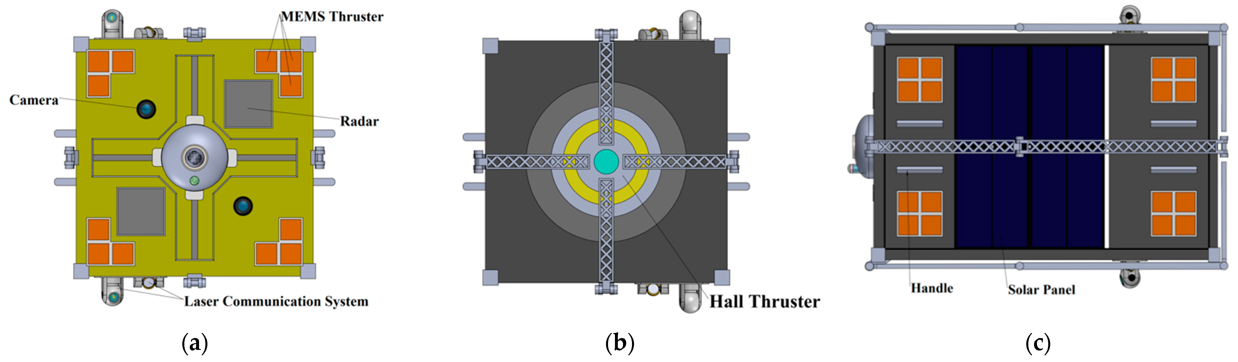
The servicing satellite proposed in this paper is a 12U CubeSat, which is mainly composed of a detection-communication system, propulsion system, attitude determination and control system, power system, and several payloads. Three views of the servicing satellite in orthographic projection are provided in Figure 2.
The servicing satellite is highly integrated, allowing it to be smaller, lighter, and easier to be operated compared to other conceptual platforms for ADR. It usually hovers 10–100 m away from the target, and, once the time is right, it will initiate the capture procedure. It is able to capture small- or medium-sized debris by using a single capture mechanism or a single servicing satellite and to capture large space debris by coordinatively using different capture mechanism or different servicing satellites. The side handles on the servicing satellite (see Figure 2c) are designed to restrict the location of the servicing satellite in the orbiter and to provide convenience for grabbing in case it loses control.
(1) Detection-Communication System
The detection-communication system consists of two phased array radars, two pairs made up of a laser transmitter and a receiver, and a sensor (see Figure 2a). The two phased array radars, located at the top and bottom of the satellite, respectively, are mainly responsible for the detection and tracing of the target with very high accuracy. The sensor at the front center of the net begins to work after the tethered net is ejected, playing the role of an alternative in case the radars are sheltered by the net. The two types of detection devices work together to achieve a continuous tracking of the target.
The laser transmitter and receiver (see Figure 3), located at the top and bottom of the satellite, is the main component of the communication system. It is used for communication between the servicing satellite and the relay satellite, and thus it helps the ground stations to monitor the status and parameters of the servicing satellite in real time.
(2) Propulsion System
The propulsion system adopts a Hall thruster (see Figure 2b), which is located at the back side of the servicing satellite. Compared with traditional chemical propulsion system, the Hall thruster has many advantages. For example, its thrust is usually small, and its performance is stable, making it very easy to control. It also features a high efficiency, long life, low power consumption, and is small, which not only reduces the requirements on the power system, but also achieves economies of scale be carrying a large number of servicing satellites in the orbiter.
(3) Attitude Determination and Control System
The attitude determination and control system has two parts, namely the adaptive control system and the auxiliary control system. The adaptive control system, which is composed of a momentum wheel and a magnetic torque converter inside the satellite, is used to control the attitude of the servicing satellite throughout the whole mission. The auxiliary control system includes 60 MEMS solid propellant micro thruster arrays on five sides of the satellite. Since MEMS thruster arrays have the advantage of simple structures, low power consumption, a fast response, and high reliability, they can be used to stabilize the attitude of the whole system during the capture phase and the post-capture phase.
(4) Power System
The power system consists of solar panels (see Figure 2c) arranged around the satellite and a set of built-in fuel cells. This system is mainly responsible for collecting energy from solar power and supplying energy to other systems.
2.3. Payloads
The payloads for capturing debris are the most important features of the whole platform. The design of the mechanisms and the way they work influence the degree of success and the effectiveness of ADR. Among all existing ADR techniques, we selected three of them as on-board payloads: the first is a harpoon, which occupies the front center of the satellite; the second is a net launcher enclosing the harpoon; and the third is four 3-DOF robotic arms standing still against the surfaces of the satellite. Detailed descriptions are as follows.
(1) Tethered Net Payload
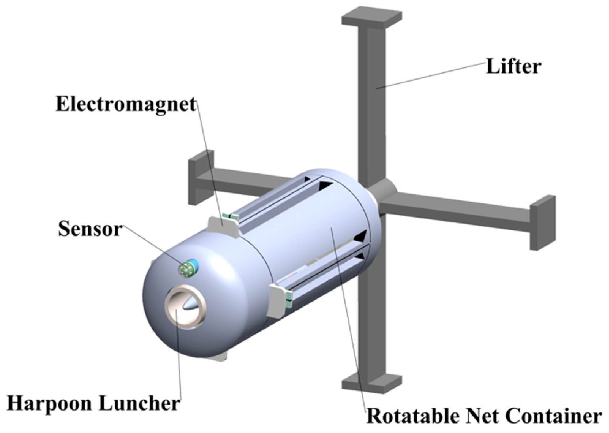
The tethered net payload is located on the front center of the satellite, with the harpoon at its center. It consists of a sensor, a rotatable net container, a net, four electromagnets attached to four corner masses, a winch, an information interface, and a lifter (see Figure 4).
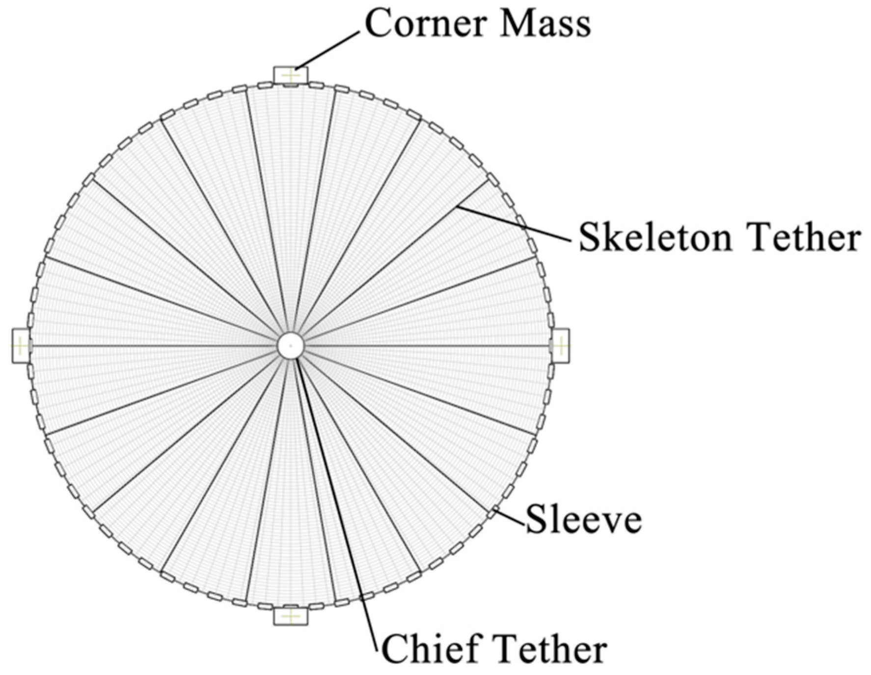
The net is initially folded and placed in the container. The net is planar and circular when it is unfolded (see Figure 5). Several skeleton tethers emerge radially from the center to the outermost sleeves located along the perimeter of the net. Pulling the chief tether can reduce the perimeter, thus closing the net. This is similar to the tether-actuated net closing manner which is proposed in [15]. In that paper, the net is square shaped and both the perimeter of the net mouth and the distance from the periphery to the center are reduced when the chief tether is pulled. But here, the net has a circular shape, only the perimeter of the net mouth is reduced, and the length of the skeleton tether is unchanged. There are four identical corner masses on the perimeter, which are used for the spinning deployment of the net as a result of centrifugal force. The payload also has a built-in lightweight computer, which is used to calculate the target’s size, its distance from the platform, and to decide when to deploy the spinning net.
(2) Harpoon Payload
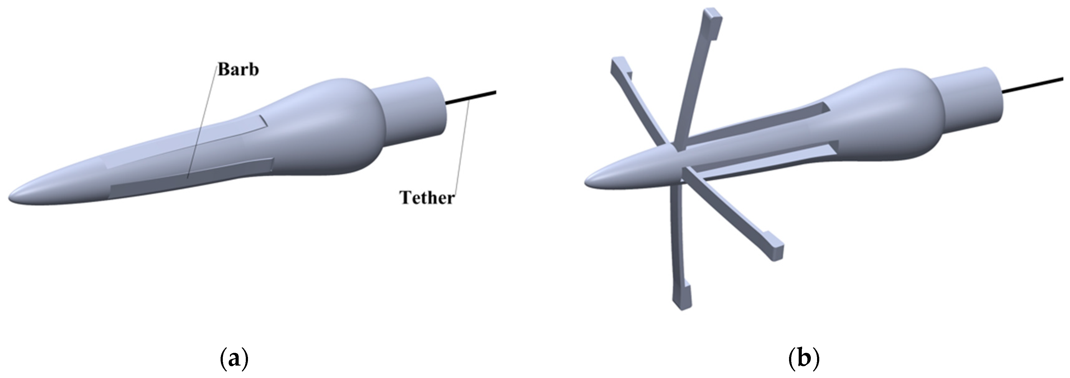
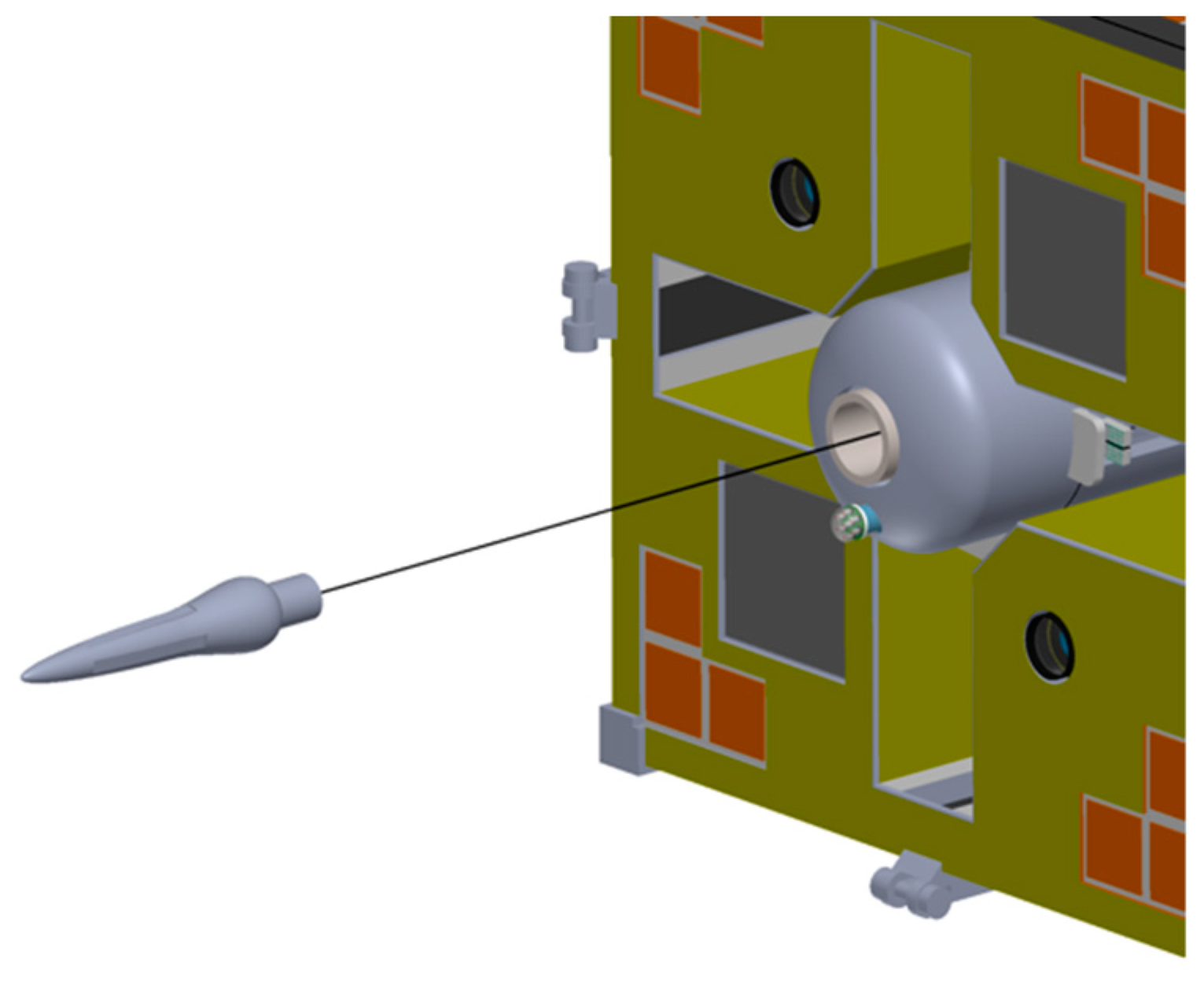
The harpoon payload is enclosed by the tethered net payload. The structure of the harpoon is relatively simple (see Figure 6), with it consisting of the main body, four barbs, a launcher, and a tether.
When the target is within the harpoon’s reach, the harpoon is shot out (see Figure 7). Once it penetrates the surface of the target, the barbs are deployed, preventing the escape of the target during tether retrieval.
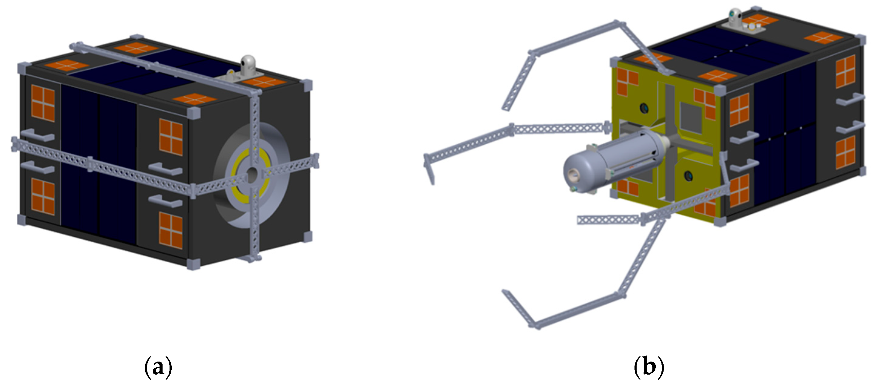
(3) Robotic Arm Payload
The robotic arm payload consists of four 3-DOF robotic arms, and each of them is fixed along the central axis of the face of the corresponding side of the servicing satellite. Before the final firm capture, for example, when the satellite is locked in the orbiter or is moving towards the target, the four arms are folded, clinging to the surface of the satellite (see Figure 8a). When the servicing satellite has accomplished a preliminary capture of the target by using the harpoon or tethered net and the target has been retrieved to an appropriate distance, the robotic arms open their mouth in reverse to grab the target and therefore achieve a firm capture (see Figure 8b).
3. Mission Scenario
The launch vehicle carries multiple servicing satellites into LEO. Based on the space debris information provided by the ground-based and space-based observations, the satellites are then transferred to the mission orbits. After orbital phasing and rendezvous, they use the tools mentioned above to capture the targets, and then transfer the targets to the graveyard orbit, or lower their orbits to re-enter the atmosphere.
3.1. Capture Process
After each servicing satellite is transferred to the designated orbit and approaches the target, the servicing satellite begins to work. The laser transmitter and receiver sends/receives real-time information to/from the ground station with the help of the relay satellite. Meanwhile, the optical cameras and the front phased array radars perform feature recognition and attitude measurement for the target. First, after obtaining the target’s information, especially its shape, status, and material, the payload to use is determined. If the target is relatively stationary, has a flat surface, and is made of material that is easy to penetrate, the harpoon can be activated to capture it. If the target is irregular in shape or is spinning at a high speed, the tethered net payload should be selected. Once the releasing condition is satisfied, the net container is ejected and begins to rotate. When the predetermined release angular speed is reached, the corner masses are released from the attachment point, pulling the net to rotate and therefore deploy. Due to the effect of inertia, the corner masses and the net keep flying towards the target. Once the net hits the target, the tension sensors on the net detect a sudden change in tension, and then the winch in the net container begins to retrieve the chief tether, so that the mouth of the net is closed, and the target is completely wrapped. Thus, the flexible connection between the servicing satellite and the target is established, and the target can be de-spun by the friction produced by the net.
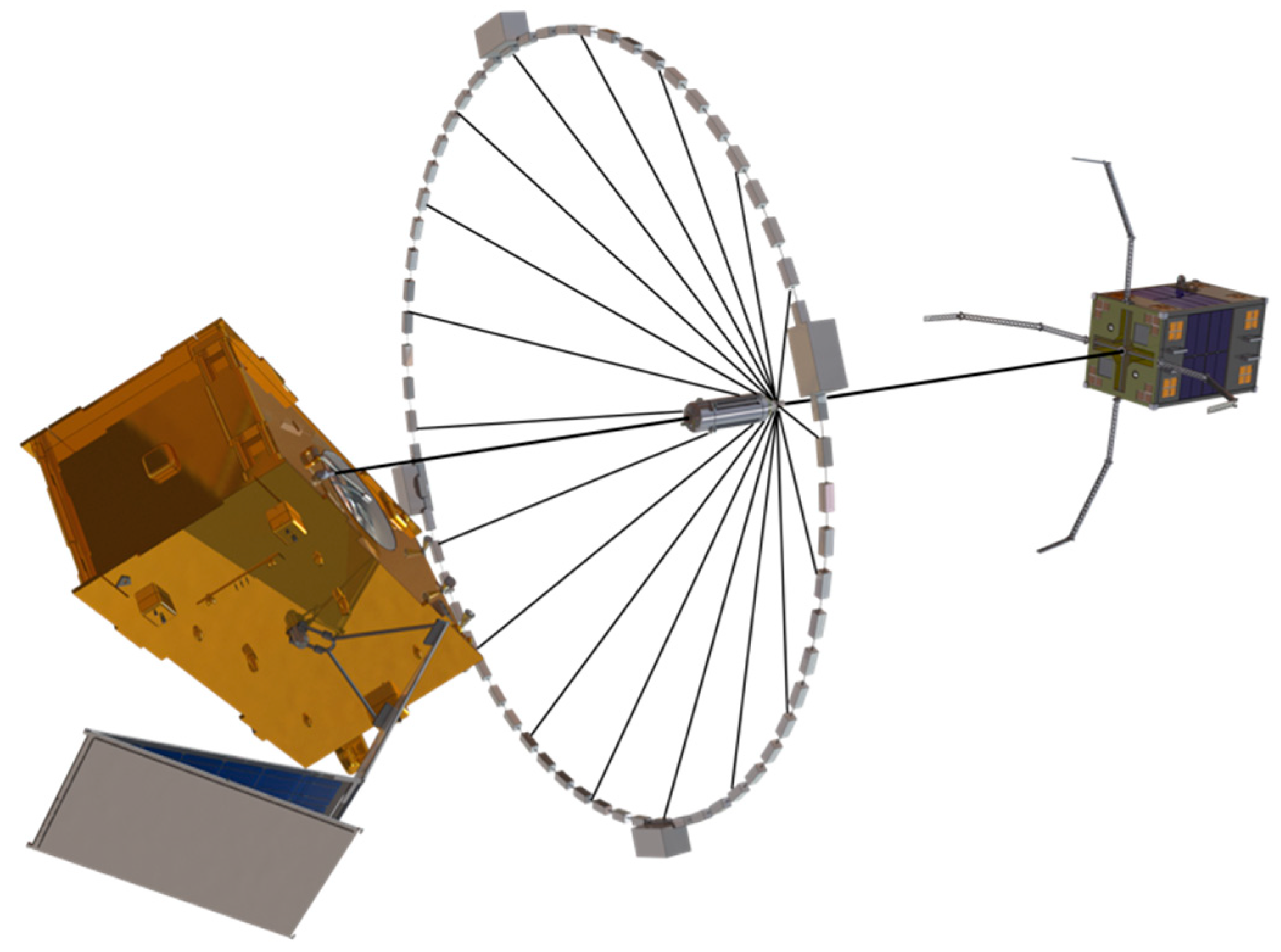
After the capture is completed by the harpoon or the net or both of them, the servicing satellite begins to shorten its distance from the target by retrieving the chief tether attached to the payload. In this process, the front detectors transmit the acquired target’s parameters to the calculation module to help it to decide when to open the robotic arms. After the target enters into the scope of action of the robotic arms, the four arms slowly open their mouth and grab the target, establishing a firm satellite-target combination, laying the foundation for the further deorbit processes. Sometimes, the three techniques can be used together (see Figure 9), in which the harpoon is used to achieve a preliminary capture, the tethered net is used to de-spin the target, and the robotic arms are used to establish a firm connection.
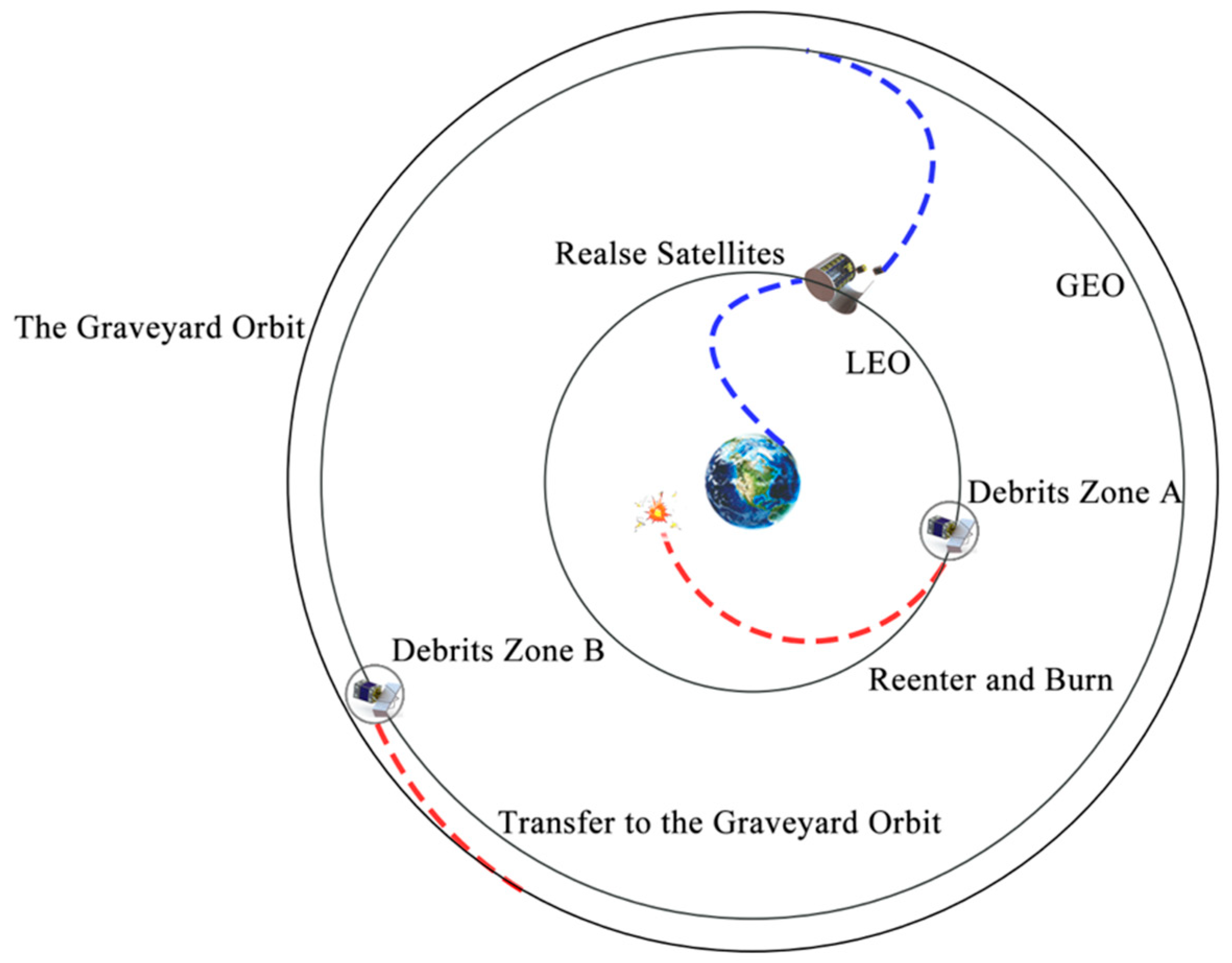
3.2. Whole Process
The whole process of ADR conducted by the servicing satellite designed in this paper is as follows (see Figure 10):
- (1)
- The orbiter is launched and sent to LEO;
- (2)
- A set of servicing satellites are released;
- (3)
- Each servicing satellite obtains the orbital parameters of the target via ground-based and space-based observations;
- (4)
- The servicing satellite transfers to the target orbit and completes the rendezvous;
- (5)
- Based on achieved target’s status, the satellite selects the capture tools and captures the target;
- (6)
- For an LEO target, the servicing satellite deorbits with the target, resulting in reentry; for a GEO target, it transfers the target to the graveyard orbit.
4. Conclusions
In this paper, we carried out conceptual research on the design of an integrated platform, also known as a servicing satellite, for the purpose of active debris removal. This paper has two main contributions. First, the proposed platform integrates three tools for capturing debris, namely, a tethered net, a harpoon, and a robotic arm, so that the platform has complementary advantages and can handle various types of debris. Second, the paper accomplishes a detailed design of the relevant mechanisms based on 3D modeling software. In further work, a prototype of the platform will be produced, and ground tests will be conducted.
Author Contributions
Conceptualization, S.L., H.Z., Y.Z., and R.Q.; investigation, S.L., Y.Z., and R.Q.; methodology, S.L.; visualization, S.L.; writing—original draft, S.L., H.Z., Y.Z., and B.N.; writing—review and editing, S.L., H.Z., B.N., and R.Q.; supervision, R.Q. All authors have read and agreed to the published version of the manuscript.
Funding
This research was funded by the Innovation and Entrepreneurship Training Program for College Students of the Beijing Institute of Technology.
Institutional Review Board Statement
Not applicable.
Informed Consent Statement
Not applicable.
Data Availability Statement
Exclude this statement.
Conflicts of Interest
The authors declare no conflict of interest.
References
- Kwok-Choon, S.T.; Madden, D.; Wilde, M.; Go, T. Capture of a Non-Cooperative Space Object using a Grasping Tool with Force Sensors. In Proceedings of the 2018 AIAA SPACE and Astronautics Forum and Exposition, Orlando, FL, USA, 17–19 September 2018. [Google Scholar]
- Gangapersaud, R.A.; Liu, G.; de Ruiter, A.H. Detumbling a Non-Cooperative Space Target with Model Uncertainties Using a Space Manipulator. J. Guid. Control. Dyn. 2019, 42, 910–918. [Google Scholar] [CrossRef]
- Virgili-Llop, J.; Drew, J.; Zappulla, R.; Romano, M. Autonomous Capture of a Resident Space Object by a Spacecraft with a Robotic Manipulator: Analysis, Simulation and Experiments. In Proceedings of the AIAA/AAS Astrodynamics Specialist Conference, Long Beach, CA, USA, 13–16 September 2016. [Google Scholar]
- Gilardi, G.; Kawamoto, S.; Kibe, S. Capture of a Non-Cooperative Object Using a Two-Arm Manipulator. In Proceedings of the 55th International Astronautical Congress of the International Astronautical Federation, the International Academy of Astronautics, and the International Institute of Space Law, Vancouver, BC, Canada, 4–8 October 2004. [Google Scholar]
- Medina, A.; Cercós, L.; Stefanescu, R.M.; Benvenuto, R.; Pesce, V.; Marcon, M.; Lavagna, M.; González, I.; López, N.R.; Wormnes, K. Validation results of satellite mock-up capturing experiment using nets. Acta Astronaut. 2017, 134, 314–332. [Google Scholar] [CrossRef]
- Hovell, K.; Ulrich, S. Attitude Stabilization of an Uncooperative Spacecraft in an Orbital Environment using Visco-Elastic Tethers. In Proceedings of the AIAA Guidance, Navigation, and Control Conference, San Diego, CA, USA, 4–8 January 2016. [Google Scholar]
- Zhang, F.; Huang, P.; Meng, Z.; Zhang, Y.; Liu, Z. Dynamics Analysis and Controller Design for Maneuverable Tethered Space Net Robot. J. Guid. Control. Dyn. 2017, 40, 2828–2843. [Google Scholar] [CrossRef]
- Sizov, D.A.; Aslanov, V.S. Space Debris Removal with Harpoon Assistance: Choice of Parameters and Optimization. J. Guid. Control. Dyn. 2021, 44, 767–778. [Google Scholar] [CrossRef]
- Clark, C.P.; Hastings, D.E.; Ricard, M.J.; Masterson, R. Comparative Assessment of Target Capture Techniques for Space Debris Removal with CubeSats. In Proceedings of the ASCEND 2021, Las Vegas, NV, USA, 15–17 November 2021. [Google Scholar]
- Eves, S. Techniques to Mitigate Space Debris. Space Traffic Control. 2017, 35–46. [Google Scholar] [CrossRef]
- Romagnoli, D.; Theil, S. De-orbiting satellites in LEO using solar sails. J. Aerosp. Eng. Sci. Appl. 2012, IV, 49–59. [Google Scholar] [CrossRef]
- Visagie, L.; Lappas, V.; Erb, S. Drag sails for space debris mitigation. Acta Astronaut. 2015, 109, 65–75. [Google Scholar] [CrossRef]
- Schall, W.O. Orbital debris removal by laser radiation. Acta Astronaut. 1991, 24, 343–351. [Google Scholar] [CrossRef]
- Phipps, C.R.; Baker, K.L.; Libby, S.B.; Liedahl, D.A.; Olivier, S.S.; Pleasance, L.D.; Rubenchik, A.; Trebes, J.E.; George, E.V.; Marcovici, B.; et al. Removing orbital debris with lasers. Adv. Space Res. 2012, 49, 1283–1300. [Google Scholar] [CrossRef] [Green Version]
- Sharf, I.; Thomsen, B.; Botta, E.; Misra, A.K. Experiments and simulation of a net closing mechanism for tether-net capture of space debris. Acta Astronaut. 2017, 139, 332–343. [Google Scholar] [CrossRef]
Figure 1.
Perspective plot of the orbiter.

Figure 2.
Three views of the servicing satellite in orthographic projection. (a) Front view, (b) back view, (c) side view.
Figure 2.
Three views of the servicing satellite in orthographic projection. (a) Front view, (b) back view, (c) side view.

Figure 3.
Laser transmitter and receiver of the communication system.

Figure 4.
The tethered net payload.

Figure 5.
The configuration of the net.

Figure 6.
The harpoon payload when the barbs are (a) inactive and (b) active.

Figure 7.
The harpoon launched from the launcher.

Figure 8.
The robotic arm payload when the arms are (a) folded and (b) unfolded.

Figure 9.
A servicing satellite conducting the capture operation.

Figure 10.
The whole process of ADR mission.

Publisher’s Note: MDPI stays neutral with regard to jurisdictional claims in published maps and institutional affiliations. |
© 2022 by the authors. Licensee MDPI, Basel, Switzerland. This article is an open access article distributed under the terms and conditions of the Creative Commons Attribution (CC BY) license (https://creativecommons.org/licenses/by/4.0/).
Share and Cite
MDPI and ACS Style
Lv, S.; Zhang, H.; Zhang, Y.; Ning, B.; Qi, R. Design of an Integrated Platform for Active Debris Removal. Aerospace 2022, 9, 339. https://0-doi-org.brum.beds.ac.uk/10.3390/aerospace9070339
AMA Style
Lv S, Zhang H, Zhang Y, Ning B, Qi R. Design of an Integrated Platform for Active Debris Removal. Aerospace. 2022; 9(7):339. https://0-doi-org.brum.beds.ac.uk/10.3390/aerospace9070339
Chicago/Turabian StyleLv, Senwei, Haojun Zhang, Yao Zhang, Bowen Ning, and Rui Qi. 2022. "Design of an Integrated Platform for Active Debris Removal" Aerospace 9, no. 7: 339. https://0-doi-org.brum.beds.ac.uk/10.3390/aerospace9070339
Note that from the first issue of 2016, this journal uses article numbers instead of page numbers. See further details here.