
Parametric Research and Aerodynamic Characteristic of a Two-Stage Transonic Compressor for a Turbine Based Combined Cycle Engine


Institute for Aero Engine, Tsinghua University, Beijing 100084, China
Aerospace 2022, 9(7), 346; https://0-doi-org.brum.beds.ac.uk/10.3390/aerospace9070346
Submission received: 9 May 2022
/
Revised: 20 June 2022
/
Accepted: 23 June 2022
/
Published: 28 June 2022
(This article belongs to the Special Issue Fluid Flow Mechanics (2nd Edition))
Abstract
:This paper researches the parametric optimization of a two-stage transonic compressor having a large air bypass at partial rotating speed according to flow analysis for a turbine-based combined cycle engine (TBCC). To obtain adequate thrust, the inlet transonic compressor of the turbofan part of the TBCC is required to have a wider frequently used corrected rotating speed range and a larger mass-flow rate at low rotating speed, which is different from a typical transonic compressor. The one-dimensional blade design parameters and flow path of the baseline two-stage transonic compressor are introduced. With the widely used CFD software Numeca, the three-dimensional flow fields of the baseline transonic compressor and effects of the flow path between Stage 1 and Stage 2 on the inlet mass flow rate are analyzed for indicating the further improvement direction. For design speed (NC = 1.0), to improve the efficiency at the design point, parametric research is carried out on Rotor 2 to optimize the shock structure and strength, resulting in enhanced efficiency at the design point due to reduced shock loss of Rotor 2. For partial speed (NC = 0.8 and 0.7), since the flow field analysis indicates that the flow blockage in S1 limits the entire mass flow rate, the parametric redesign of stator S1 aims at obtaining an increased blade throat width to enhance the flow capacity of S1. Simulation confirms the increase in the mass-flow rate and efficiency at partial speed due to the reduction in flow blockage and related viscous losses. Aerodynamic analysis at representative operation points indicates that the modifications of R2 and S1 lead to obvious aerodynamic improvement at all rotating speeds (NC = 1.0 to 0.7), while maintaining sufficient stall margin.
1. Introduction
Recently, the high Mach number engine has become one of the most important research directions in aerospace for application in hypersonic aircraft, considered as the long-term future of long-range aviation [1,2], and has attracted lots of research interests [3,4,5,6]. The turbine-based combined cycle engine (TBCC) is a suitable propulsion power for high Mach number aircraft, which is able to provide wide Mach number operation range, reusability, flexibility and horizontal take-off and landing ability [7].
In the 1960s, the P&W J58 engine powering the SR-71 is one of the most successful high Mach number engines adopting the turbine-based combined cycle engine concept [8]. With the J58 engine, the SR-71 is able to fly up to Mach 3+. The geometry-variable supersonic inlet is used to match the mass-flow characteristic with the engine by moving the central cone according to the flight Mach number [9]. The P&W J58 engine is the distinguished representative of early high-speed engines, which experiences the process of design, testing and application.
One of the important research directions on TBCC engines is the concept research, modeling and integration analysis for evaluating the overall performance. In 2004, Clough developed a quasi-1D TBCC engine performance model and hybrid optimization scheme to evaluate several TBCC engine concepts for determining the most suitable type for the first stage of a two-state-to-orbit launch vehicle power [8]. Research shows there exists an upper limit of Mach number 4.25 for operation of turbo-machinery engines due to the assumed compressor exit temperature limit of 1000 K; then, the pre-cooling or transition to pure ramjet mode is required for higher flight Mach number [8]. Research also indicates the turbine-bypass engine (TBE), capable of adjusting the bypass ratio, has superior thrust and specific impulse performance in the researched TBCC concepts [8]. In 2006, the cycle analyses and system studies on different TBCC engines for powering the ultra-long-haul (about 15,000 km) supersonic cruise airliner of Mach 4.5 were conducted by Sippel [10]. The thermodynamic performance of the advanced turbojet engine and variable cycle engine (VCE) was calculated, and the evaluation of overall performance in a realistic flight mission indicates that the VCE has a notable efficiency advantage with a significant subsonic cruise portion in the mission by increasing the bypass ratio and better flight range (+1000 km) [10]. In 2009, the high Mach transient engine cycle code (HiTECC), a highly integrated simulation tool composed of models for each of the TBCC systems with performance and controllability affecting the thrust and operability of the propulsion system, was developed by Gamble et al.; it is able to research the TBCC engine in different operation modes [11]. To further improve the analysis tool, the hydraulic and kinematic system model [12] and the thermal management and fuel system model [13] were developed.
The operation mode transition from turbojet to ramjet is also one of the important research directions for TBCC propulsion systems. In 2009, Slater et al. carried out a steady-state CFD simulation at different splitter cowl positions (0, −2.0, −4.0, −5.7 deg) for the inlet mode transition flow field at Mach 4 from turbine flow-path to parallel dual-mode ramjet/scramjet in a TBCC propulsion system [14]. Research indicated the accurate modeling of shock waves, boundary layers and porous bleed regions were dominant factors for assessing the inlet static and total pressure, bleed flow rates and bleed plenum pressures [14]. In 2016, an air-breathing high Mach number propulsion tool (HiMach), adopting component-level modeling (inlet, splitter, fan, compressor, combustor, turbine, mixer, nozzle and duct), was developed by Zhang et al. for steady-state and transient performance analysis of turbo/ram/wind-milling ram mode and mode transition [15]. A simplified turbojet wind-milling model was incorporated to consider the shutdown process of the turbojet during mode transition. By using the HiMach code, the mode transition for a small-scale tandem TBCC engine was researched, and the hyperburner inlet Mach number and total pressure were found to change rapidly during transition, especially from turbojet to wind-milling mode.
Another important research direction for high-speed engines is the inlet intake, which has a remarkable influence on the proper operation of the high-speed engine by matching the mass-flow characteristic. In 2008, from the view of integrated performance analysis of a TBCC engine, Ou-Yang et al. proposed the tri-variable adjustable rectangle hypersonic intake concept [16]. A multi-objective optimization algorithm was applied to acquire the geometry-variable scheme and the control law of this intake at off-design points. Simulation shows that the proposed geometry-variable intake matched well with the turbofan/ramjet in the specified Mach regime [16]. In 2016, a novel concept of inward turning inlet for application in the TBCC, the internal wave rider (IWR) inlet, was researched by Huang et al. [17]. This novel inlet is capable of changing cross-sectional area with smooth curvature transition for high total pressure recovery [17]. In 2021, Vanna et al. conducted three-dimensional high-fidelity simulations, based on a high-order and time-accurate large-eddy-simulation model with a sharp-interface immersed boundary method, on a hypersonic ramjet intake of Mach 5 and obtained a detailed characterization of the unsteady behavior of the intake [18]. Three blockage levels of intake channels were researched, and two main unsteady phenomena with different frequencies were found [18]. Then, related researchers proposed a multi-objective optimization frame, composed of a steady compressible RANS solver and generic algorithm, to minimize the intake drag coefficient while boosting the static and total pressure ratios [19]. For the optimized designs, the flow field, friction and pressure coefficients of the wall were analyzed to provide the physical reasons for aerodynamic performance improvement [19]. This work developed a versatile and valuable method for designing the high-speed inlet intake.
Related researchers provided a comprehensive summary of TBCC engine technology development and pointed out the technical issues that need to be dealt with. In 2009, Walker et al. reviewed the history of the air-breathing hypersonic engine programs and indicated the advantages of the TBCC engine in reusability, flexibility and multi-task capability as well as the way head [7]. In 2012, Foster et al. summarized the critical TBCC-enabling technologies: (1) mode transition from low to high speed, (2) high Mach turbine engine and (3) innovative TBCC integration [20]. To address these challenges, NASA initiated Combined-Cycle Engine Large Scale Inlet Mode Transition Experiment (CCE-LIMX) with the goal of researching: (1) the dual integrated inlet operability and performance issues (unstart constraints, distortion constraints, bleed requirements and controls), (2) mode transition sequence elements and (3) turbine engine transients during transition [20].
From the view of aerodynamic design, the high flight Mach number of the TBCC engine will cause a significant increase in inflow total temperature and therefore will lead to a larger reduction in the corrected rotating speed of the compressor in the turbofan part. However, the front compressor has to maintain a high inlet mass-flow rate to ensure that the engine has sufficient thrust to accelerate the aircraft to reach the starting Mach number of the ramjet mode. How to increase the inlet mass-flow rate at partial rotating speed and maintain relatively high efficiency is one of the challenges in the design of a compression system for a TBCC engine.
To research this problem, this paper is devoted to parametric research according to flow analysis of a two-stage transonic compressor for the turbofan part of a TBCC engine. Firstly, this paper introduces the baseline two-stage transonic compressor design parameter and analyzes its flow fields, aerodynamic characteristics and the effects of the flow path between stages for indicating the improvement direction. Then, parametric research is carried out on Rotor 2 by altering the camber angle distributions to improve the efficiency at the design point. Next, to enhance the mass-flow rate at partial speed ( and ), the stator S1 is modified to increase the throat width by enhancing the camber-line front loading level. Simulation indicates the modifications of R2 and S1 lead to obvious performance improvement at all calculated rotating speeds (), while keeping sufficient stall margin.
2. General Consideration of the Transonic Compressor: A Large Bypass Flow-Path in Stages to Improve Compressor Mass-Flow Rate at Partial Speed
Introduction of the Baseline Two-Stage Transonic Compressor
The front portion of this compression system for a TBCC engine is a two-stage transonic compressor with a design mass-flow rate of 60 kg/s and a total pressure ratio of 3.30 in single flow-path mode (SFM). The objective aerodynamic performance of this transonic compressor at different rotating speeds () is shown in Table 1. Compared with a typical compressor, one key feature of this transonic compressor is the lower reduction rate of the inlet mass-flow rate with the decrease in relative rotating speed NC In other words, this compressor component is required to provide a higher relative mass-flow rate at partial speed () than a typical compressor. To achieve this objective, a bypass flow-path is designed between Stage 1 and Stage 2. The bypass mass-flow ratio required at different corrected rotating speeds is shown in Table 2.
According to the objective aerodynamic performance in Table 1 and Table 2, a baseline design of the front transonic compressor has been established with the meridian view shown in Figure 1. The baseline transonic compressor has a fixed inlet guide vane (IGV) with a relatively large negative pre-swirl at the blade hub to the mid portion (Figure 1c), aiming at increasing the reaction level of Rotor 1 around the hub portion to decrease the inlet Mach number of downstream stator S1 around the hub. The blade design (especially the selection of relative thickness distribution, the leading edge and trailing edge thicknesses) has considered the requirements of structural integrity.
For the baseline compressor, Stage 1 has a load coefficient with a flow coefficient , which is of high aerodynamic load level. Stage 2 has a lighter load coefficient with a flow coefficient As shown in Table 3, Rotor 1 and Rotor 2 have relatively high blade tip tangential velocity of 463.5 m/s and 450.0 m/s, respectively. The hub-to-tip ratios at the leading edge of Rotor 1 and Rotor 2 are 0.505 and 0.748, respectively. The low aspect ratio () design is used in both Rotor 1 and Rotor 2 to improve the chord length for enhancing the blade Reynolds number and blade structure strength.
3. Effect of Adding the Bypass Flow Channel
3.1. Numerical Method
The aerodynamic characteristics of the transonic compressor are obtained by numerical simulations conducted by commercial CFD software Numeca. In the simulation, the steady Reynolds-averaged Navier–Stokes method is used with a central difference scheme and Spalart–Allmaras turbulence model. The selection of the Spalart–Allmaras (SA) turbulence model for the flow simulation of axial compressor has been validated by several studies on Rotor 67, Rotor 37 and a counter-rotating compressor and has obtained good agreement with the experimental results in both efficiency and total pressure ratio [21,22]. For inlet boundary conditions, the inflow has a uniform property distribution of air with a total temperature of 288.15 K and total pressure of 101,325 Pa in the axial direction (Figure 2a). For outlet boundary conditions, the radial equilibrium option is used for both main-flow and bypass outlets with static pressure specified at the mid location.
The grid used in numerical simulation (Figure 2b) is generated by using the software AutoGrid5. The mesh of each blade has a multi-block O4H topology, and the wall cell height is set to 0.002 mm with the expansion ratio set to 1.15. This results in at the blade surface and satisfies the requirement of the Spalart–Allmaras turbulence model. For most of the blade rows, the O-block around the blade has 25 to 33 nodes in the normal direction of the blade surface for capturing the development of the boundary layer. The number of stream-wise nodes on the blade surface is in the range of 53 to 117, and the number of radial nodes of each blade is in the range of 61 to 113. The grid number of the mesh is for single flow-path mode (SFM) and for double flow-path mode (DFM). The selection of the grid scale is according to the balance of calculation accuracy and computing time, which is due to the relatively large amount of numerical computation of this research.
3.2. Baseline Compressor Performance
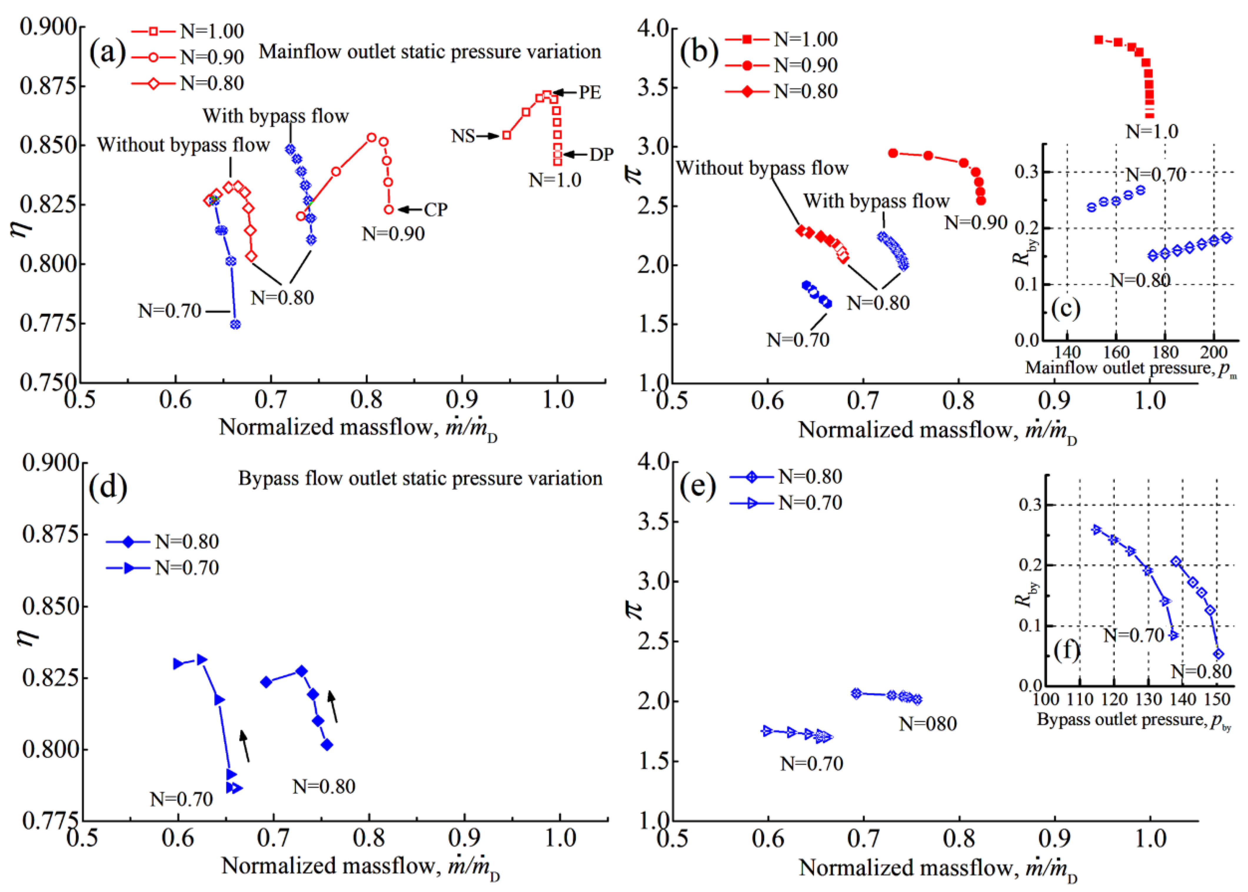
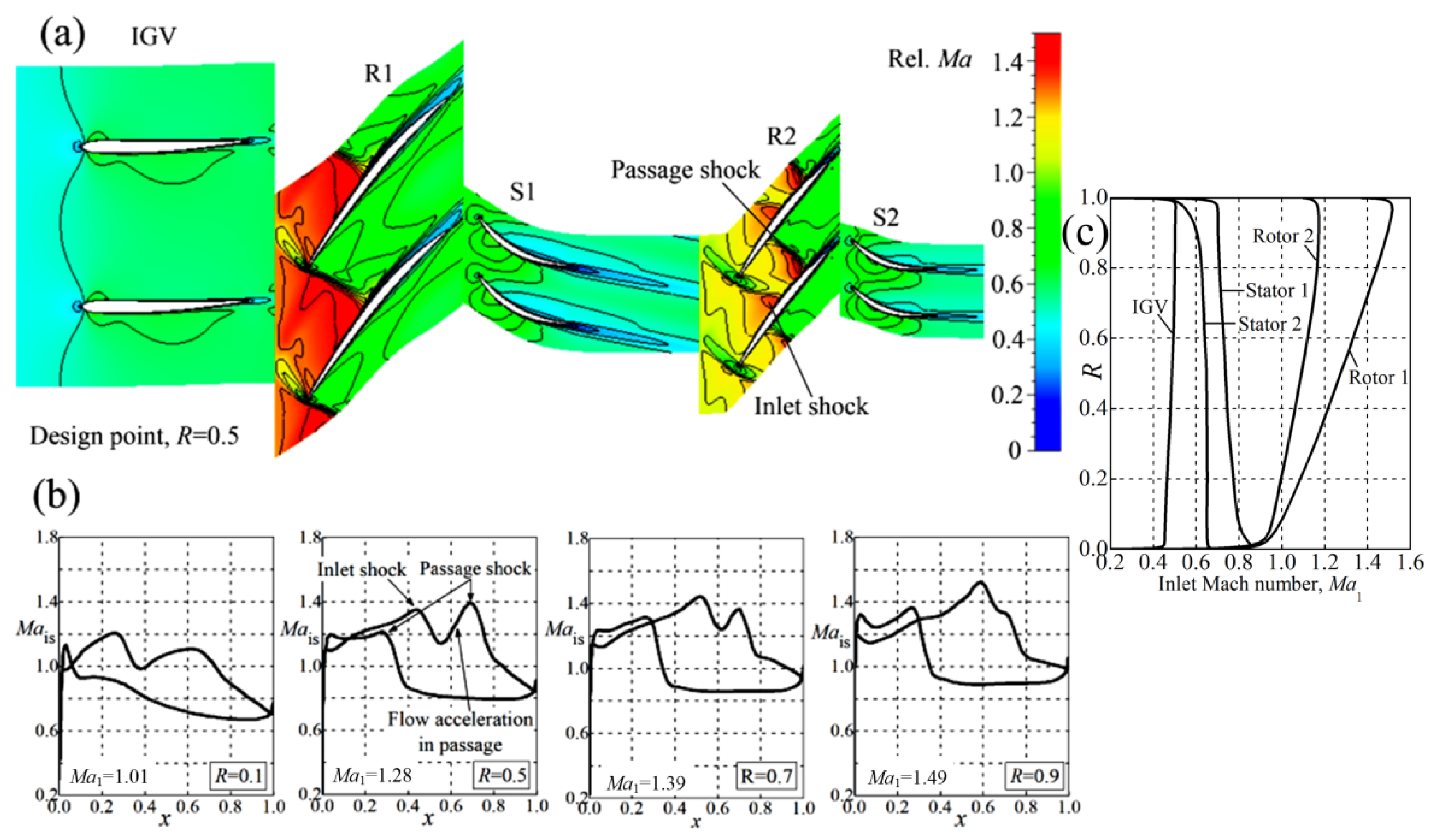
With the above numerical simulation method, the aerodynamic characteristics of the main flow and bypass flow of the baseline two-stage transonic compressor at different rotating speeds () are calculated (Figure 3). For main-flow aerodynamic characteristic (subgraph (a)–(c)), the static pressure of the main-flow path outlet is gradually increased with fixed bypass flow outlet pressure. As shown by Figure 3a,b, the baseline two-stage transonic compressor has a mass-flow rate of 61.2 kg/s and efficiency of 0.846 with a total pressure ratio of 3.32 at the design point. The stall margin is 24.2% for the design rotating speed 0. The flow field relative Mach number (Figure 4a) indicates that the Rotor 2 operates at choke condition with strong inlet shock caused by the flow expansion along the positive curvature and there is significant flow acceleration in cascade passage, resulting in strong passage shock (Figure 4a,b). At the tip region, the impinging points on the suction surface of the inlet shock and passage shock are merged; therefore, only one peak is observed (Figure 4b, R = 0.9). The strong shock strength of Rotor 2 suggests the potential for improving efficiency by optimizing the shock structure through blade modifications.
At relative rotating speed , the baseline two-stage transonic compressor has a mass-flow rate of 50.4 kg/s and efficiency of 0.823 with a total pressure ratio of 2.55 at the choke point (CP, Figure 3a). The compressor stall margin reaches a sufficient level of 30.3%. In general, the aerodynamic performance of the baseline two-stage transonic compressor has reached the design requirements at and in Table 1, but there is still improvement potential at the design point.
3.3. Effect of the Bypass Flow-Path
For partial relative rotating speed , the aerodynamic characteristics with bypass flow off and on are both calculated. As shown in Figure 3a, once the bypass flow-path is enabled, the relative mass-flow rate of the entire transonic compressor at choke condition significantly increases from 0.679 to 0.742, which corresponds to a 3.85 kg/s increment in physical mass-flow rate, which shows the effectiveness of adding a bypass flow-path between stages. However, at choke condition, the physical mass-flow rate of the baseline compressor is 45.41 kg/s and 40.55 kg/s for relative rotating speed , respectively, which is still below the targets in Table 1. This requires the optimization of the blade to further improve the physical mass-flow rate at partial speeds.
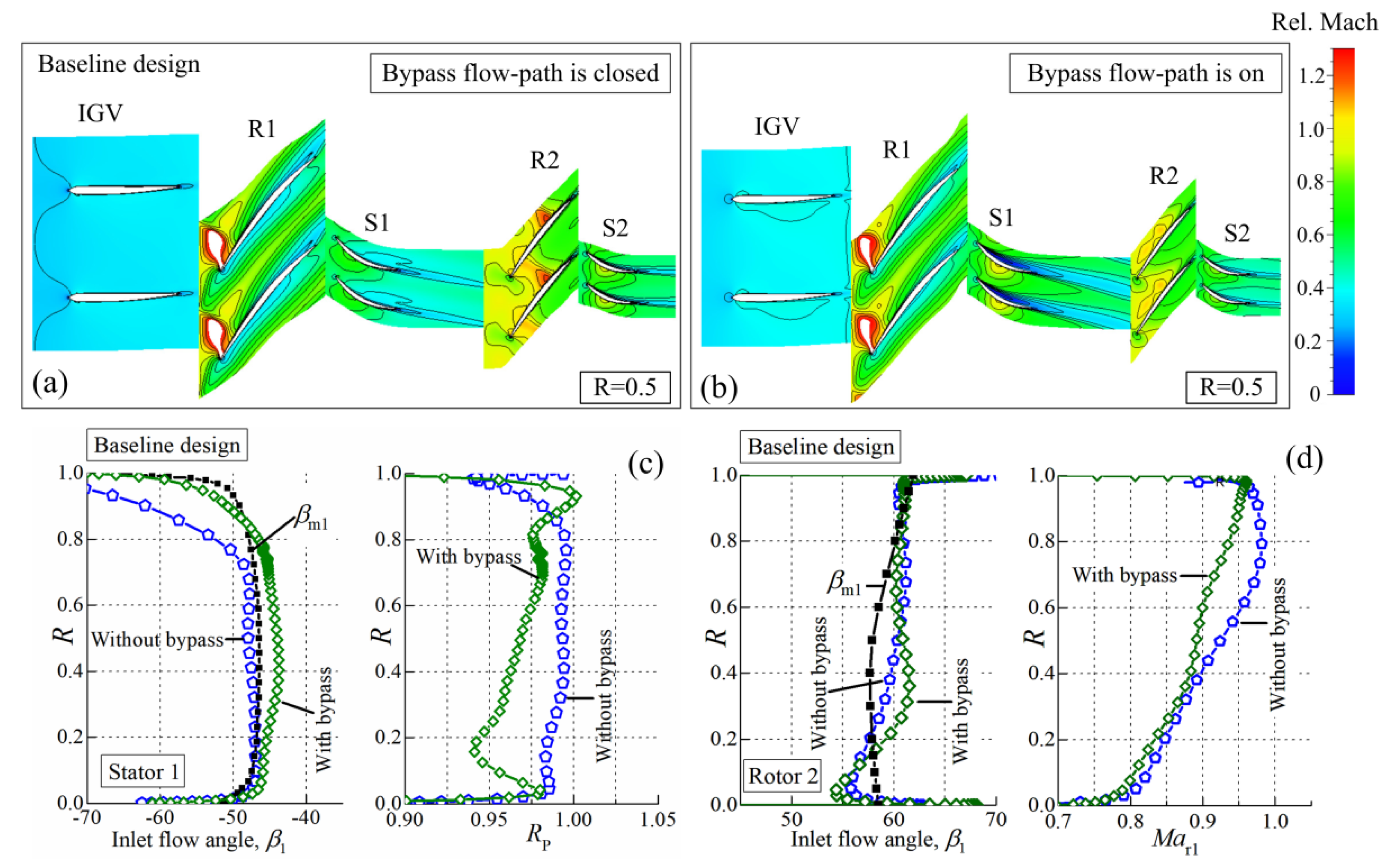
To find the blade optimization direction, the flow fields of the baseline two-stage transonic compressor at choke condition with/without bypass flow are shown in Figure 5. With closed bypass flow-path (Figure 5a), the flow blockage appears at the rotor R2, limiting the entire inlet mass flow rate of the compressor. Once the bypass flow-path is open (Figure 5b), the entire mass-flow rate is significantly enhanced and the stator S1 turns into a deep negative incidence condition with total pressure recovery coefficient substantially decreased (Figure 5c). Meanwhile, the flow blockage in the rotor R2 disappears due to the flow bypass effect (Figure 5b). The relative inlet Mach number of rotor R2 from blade span decreases and the relative inlet angle from increases (Figure 5d), which is consistent with the flow field observations.
4. Parametric Research of Rotor 2
According to the calculation result of the baseline two-stage transonic compressor, the Rotor 2 operates at deep choke condition around the design point, which suggests the potential for improving performance by optimizing the rotor blade. Therefore, by using the parametric blade design method developed in [22], rotor R2 is modified by altering the normalized camber angle distribution , with the objective of improving the efficiency while maintaining sufficient stable operation range.
4.1. Modification of the Rotor 2 Normalized Camber Angle Distribution
According to the research by Miller et al. [23] and Venturelli et al. [24], the inlet shock strength is significantly influenced by the flow expansion/compression angle along the suction surface. In addition, the researches by Wadia et al. indicate that the blade throat area is able to remarkably influence the shock structure and flow capacity of the transonic rotor blade [25]. The researches by Burguburu et al. and Wang et al. have proven that blade geometry modification is an effective way to optimize shock structure for transonic rotor performance improvement [26,27,28]. Therefore, in the blade optimization of rotor R2, the normalized camber angle distribution is altered to make the blade suction surface angle at the shock impinging point higher than that of baseline design while expanding the blade cascade throat width . This modification direction is determined based on two considerations:
- (1)
- Keeping the blade suction surface angle at inlet shock impinging point higher than that of baseline design, aiming at decreasing the inlet shock strength by reducing the flow expansion along the blade suction surface. This is because the pre-shock Mach number at suction surface impinging point increases with the enhancement of the inflow Mach number and flow turning angle :
Equation (1) shows the approximation of pre-shock Mach number by simplifying this flow process to a Prandtl-Meyer flow, is the Prandtl–Meyer function.
- (2)
- The larger blade cascade throat width is able to reduce the degree of flow blockage around the throat location for decreasing the strength of passage shock.
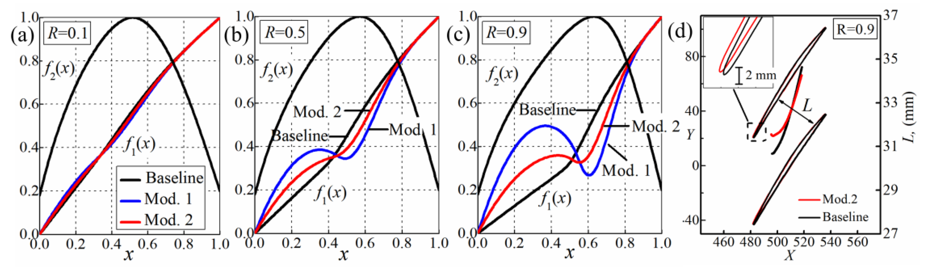
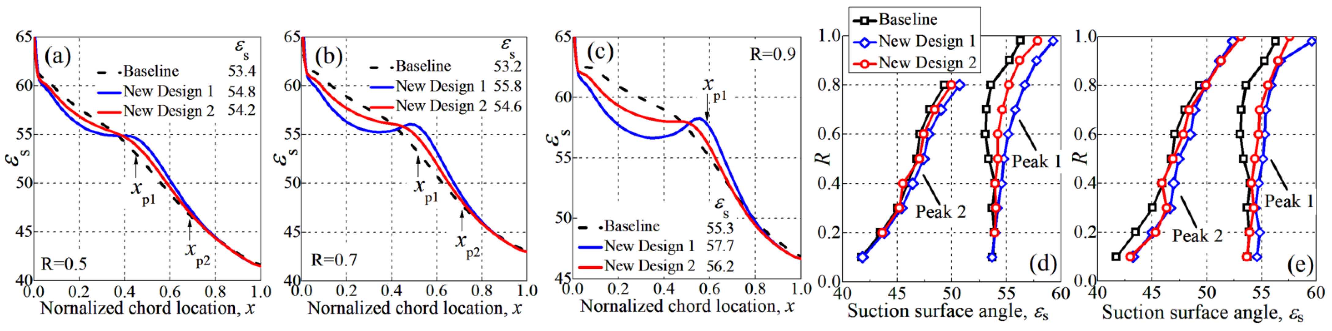
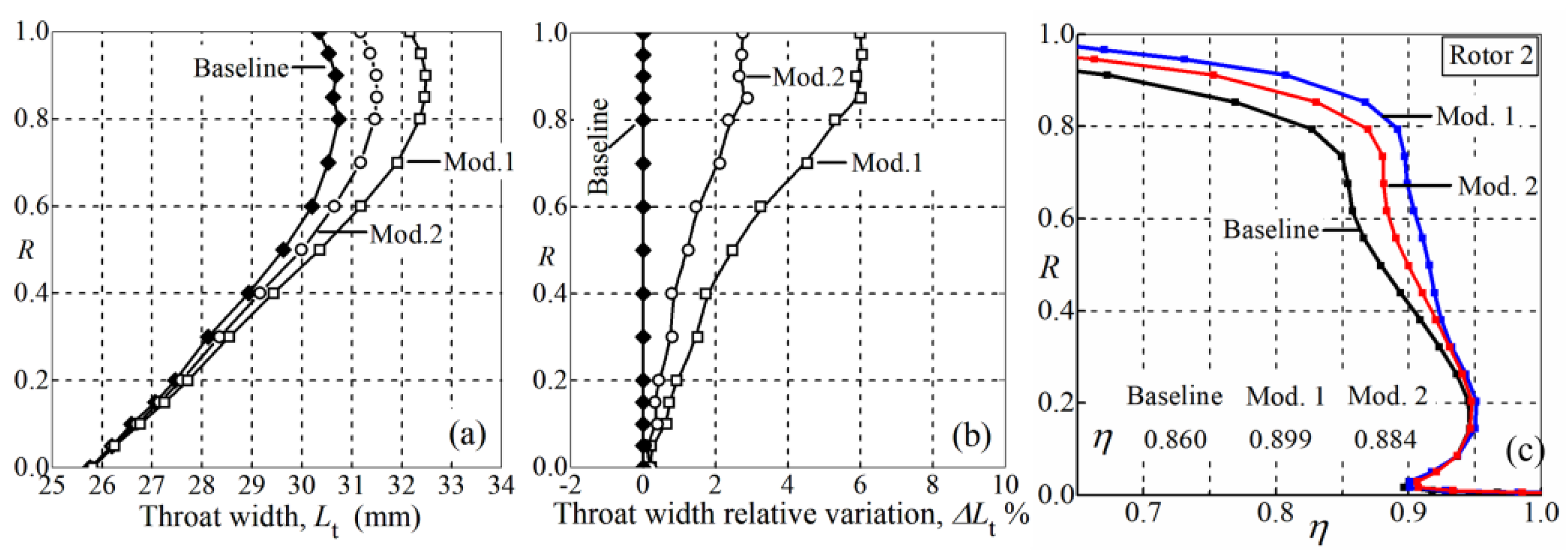
Then, after several tests, the Rotor 2 normalized camber angle distribution is altered to have rapid positive turning, then turn into a pre-compression trend and finally return to a rapid increase to TE (Figure 6), which is able to obtain the targets in (1) and (2). Mod.2 is the interpolation of the baseline and Mod.1. As shown by Figure 7, the blade suction surface angle at the peak Mach number location of Mod.1 and 2 becomes higher than the baseline design. Specifically, for Mod.2, the increase in suction surface angle at the inlet shock location (peak 1) is 0.8°, 1.4° and 0.9° at blade span (Figure 7a–c), respectively. Simulation indicates the inlet shock location moves towards LE to some extent due to the blade modifications, but the enhancement of suction surface angle of Mod.1 and Mod.2 is maintained or increased (comparing Figure 7d,e). The enhancement of suction surface angle leads to reduction of flow turning angle before the inlet shock and therefore results in decreased inlet shock strength (Figure 8a–d). Besides, the reduction of inlet shock strength tends to decrease the passage shock strength if no substantial variation of flow acceleration in passage. Meanwhile, Mod.1 and Mod.2 obtain increased blade throat width , and the magnitude of increment rises from (Figure 9a,b), which reduces the flow acceleration in the mid to hub portion of Rotor 2 and weakens the passage shock (Figure 8a,b,e). Corresponding to the flow field variation, the blade aerodynamic load distribution becomes more uniform (Figure 8f,g).
The reduction in shock strength leads to a significant increase in efficiency from blade span (Figure 9c). The efficiency of Mod.2 increased by 2.1%, 2.9% and 7.6% at blade span R = 0.5, 0.7 and 0.9, respectively. The larger efficiency increase of Mod.1 suggests the improvement is roughly proportional to the reduction in pre-shock Mach number. In addition, according to Figure 6d, the blade surface displacement caused by the alteration of is very small due to the low camber angle, differing slightly in the LE and mid region. However, the considerable efficiency gain of Mod.1 and 2 indicates that the transonic rotor performance is sensitive to the variation of geometry.
4.2. Aerodynamic Influence of the Rotor 2 Modifications
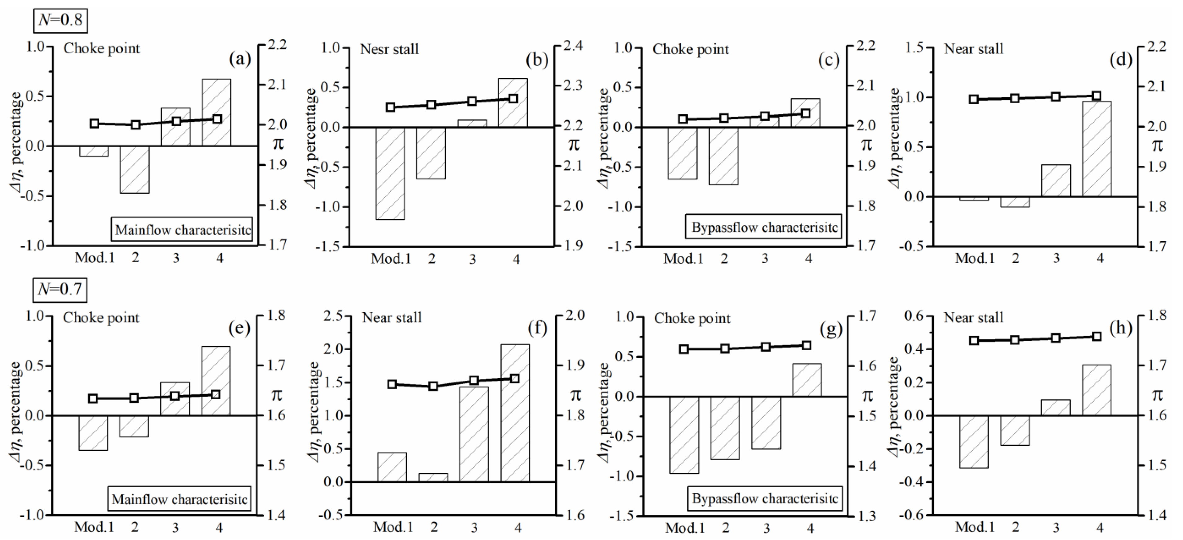
To comprehensively evaluate the effect of Rotor 2 modification on the compressor performance, Figure 10 and Figure 11 summarize the relative variation of efficiency and corresponding total pressure ratio at representative operation points for relative rotating speeds from For the single flow-path mode (SFM), Mod.2 achieves efficiency improvements than baseline design at most operation points for relative rotating speed from (Figure 10). Mod.2 shows better performance than Mod.1 at peak efficiency and near stall points (Figure 10b,c,e,f,h,i), which is due to the weaker inlet shock strength at these two conditions. This is because with the increase in back pressure, the downstream passage shock will gradually move upstream and disappear, becoming a single shock system formed by the inlet shock. Then, the inlet shock will also move towards the blade LE, and its strength is mainly determined by the inlet Mach number and the flow expansion angle . With almost same inlet Mach number , the flow expansion angle of Mod.2 is lower than that of Mod.1 due to the higher value of suction surface angle , resulting in lower inlet shock strength and shock loss level, which explains the efficiency advantage of Mod.2 over Mod.1 at peak efficiency and near stall points.
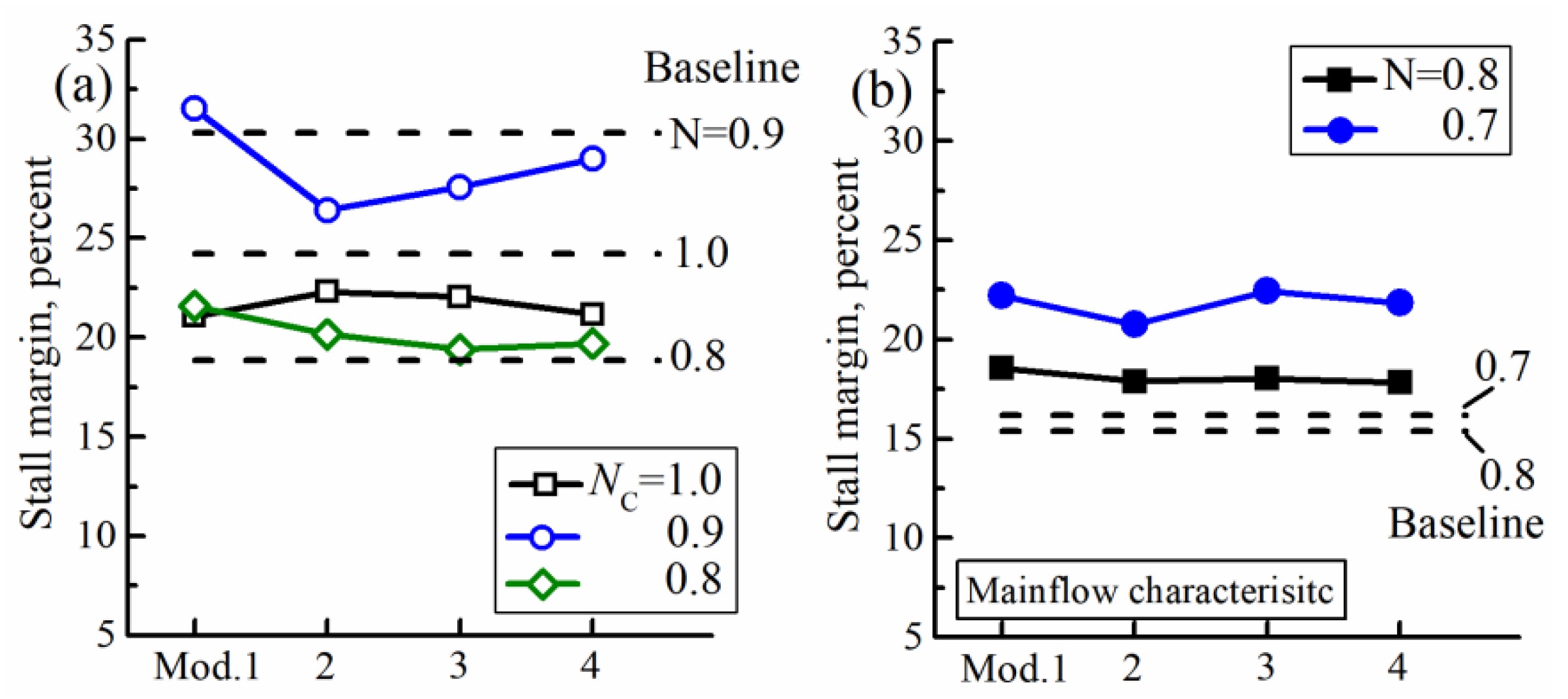
As shown by Figure 10, Rotor 2 modification almost has no effect on the pressure ratio at design point, but some impact at peak efficiency and near stall points are observed. The variation of stall margin caused by the Rotor 2 modification is little and the Mod.1 and 2 still have sufficient stable operation range (Figure 12a).
For the double flow-path mode (DFM), Mod.1 and 2 show some reduction of efficiency in both main-flow and bypass-flow characteristics (Figure 11). The flow parameter analysis indicates that the efficiency degradations of Mod.1 and 2 at the choke point are caused by a higher loss of stator S1 due to the change in the flow match and bleed air ratio at partial speed However, for near stall points, the lower efficiency level of Rotor 2 is responsible for the efficiency degradations of Mod.1 and 2 due to the stronger inlet shock caused by the lower suction surface angle of modified Rotor 2 at blade front portion , compared with baseline design (Figure 7a–c).
As shown by Figure 11, the Rotor 2 modification has little impact on the pressure ratio . Different from the SFM, the modifications of Rotor 2 lead to considerable improvement of stall margin in double flow-path mode (DFM), especially at low rotating speed (Figure 12b). Analysis of flow parameters indicates the stall margin improvement is due to the increased total pressure ratio at near stall and larger stable mass-flow rate range.
5. Parametric Research of the Stator S1
5.1. Modification of Stator S1 Normalized Camber Angle Distribution
For stators, according to the research by Aungier [29], the blade throat opening is able to significantly influence the flow capacity or the choke mass-flow rate. The analysis in Section 3 indicates that the flow choke in Stator 1 limits the entire mass-flow rate at rotating speed Therefore, this section is devoted to altering the normalized camber angle of stator S1 to increase the blade throat opening for enhancing the compressor mass-flow rate at partial speeds.
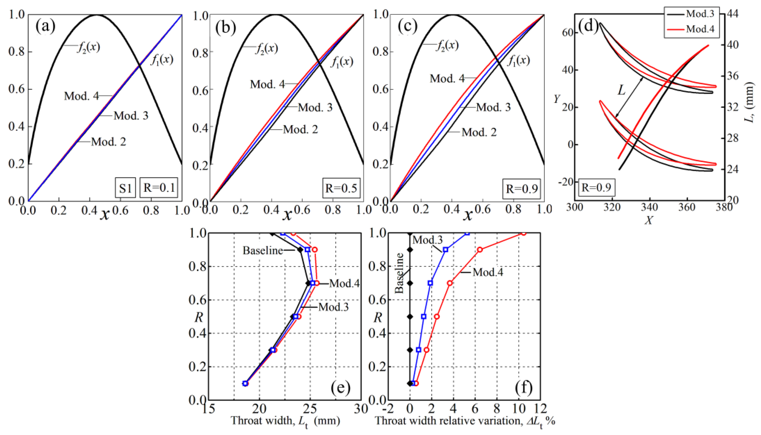
On the basis of Mod.2, the front loading level of normalized camber angle distribution is increased to obtain Mod.3 and 4, as shown by Figure 13a–c. In Figure 13e, the increase of blade throat width is roughly proportional to the enhancement of front loading level of . For Mod.4, the throat width is increased by 2.5%, 3.7% and 10.5% at , respectively (Figure 13f), suggesting enhanced flow capacity.
5.2. Aerodynamic Influence of the Stator 1 Modifications
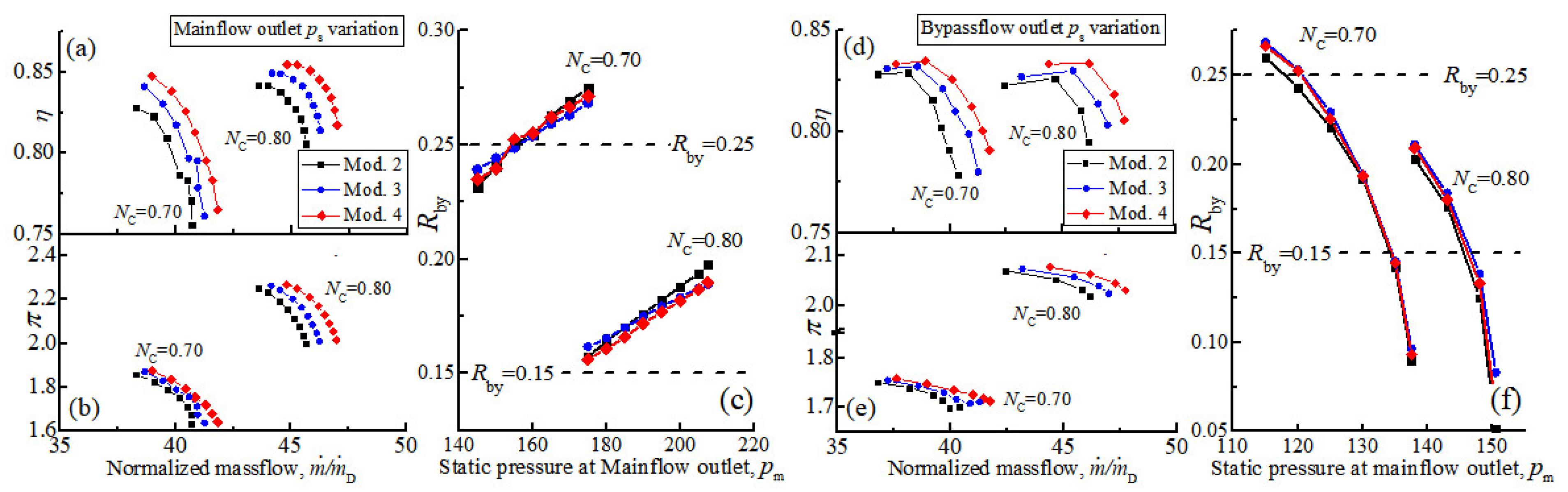
With the increase of blade throat width, simulations indicate the compressor mass-flow rates of Mod.3 and Mod.4 are significantly larger than Mod.2 (Figure 14). For the main-flow characteristic, Mod.4 achieves increments in mass-flow rate of 1.35 kg/s and 1.12 kg/s at rotating speeds , respectively, relative to Mod.2. The compressor mass-flow rate of Mod.4 reaches 47.0 kg/s and 41.8 kg/s at choke condition of relative rotating speeds and 0.7, respectively, which reach the target in Table 1. The impact of stator S1 modification on the ratio of bypass flow is very limited, and the difference is within 1.0% (Figure 14 c,f).
On the aerodynamic performance (Figure 10, Figure 11 and Figure 12), for the single flow-path mode (SFM), Mod.3 and Mod.4 with increased S1 blade throat width are able to maintain the efficiency advantage at the design point of and show larger efficiency gain than Mod.2 at both peak efficiency and near stall points (Figure 10). The impact tendency of S1 modification in stable operation range is different at each rotating speed, but the variation magnitude is slight (Figure 12). Sufficient stall margin is kept by Mod.4 with values of 21.2%, 29.0% and 19.7% at rotating speeds of of SFM (Figure 12a), respectively.
For the double flow-path mode (DFM), Mod.3 and Mod.4 both achieve obviously higher efficiency than Mod.2 in entire operation range for relative rotating speed and (Figure 14a,d). The influence of stator S1 modification on pressure ratio is very limited, and only a slight pressure ratio increment for Mod.4 is observed (Figure 14b,e), which is caused by the improvement of the total pressure recovery coefficient of stator S1. In addition, the efficiency increment is positively correlated to the flow capacity enhancement of stator S1 due to the further decreased flow blockage and lower loss coefficient, by comparing Mod.3 and 4 in Figure 14. The stall margin of Mod.4 is 17.8% and 21.9% at of DFM, respectively, reached the target in Table 1.
6. Conclusions
This paper is devoted to parametric research and flow analysis of a compression system for the turbofan part of a TBCC engine. A baseline two-stage transonic compressor with a bypass flow-path between Stage 1 and Stage 2 is introduced with emphasis on flow field analysis to indicate the further modification direction for better aerodynamic performance. According to the flow analysis, Rotor 2 and Stator 1 are modified:
- (1)
- The target of Rotor 2 modification is to improve efficiency at choke condition by decreasing the shock system strength. The modification of Rotor 2 is achieved by altering the normalized camber angle distribution for reducing the turning angle of the suction surface at the inlet shock impinging point while slightly increasing the blade throat width. Simulations indicate the strength of shock structure is obviously reduced and the blade loading distribution becomes more uniform, leading to the efficiency improvement of modified Rotor 2 at design point. Compared with Mod.1, Mod.2 has positive efficiency gain at more operating conditions, which atrributes to the weaker inlet shock-wave strength of Mod.2 at single shock mode due to the higher suction surface angle in the front portion.
- (2)
- The target of stator S1 modification is to enhance the compressor mass-flow rate at partial rotating speeds by improving the flow capacity. With Mod.2 as the basis, the front loading level of normalized camber angle distribution of S1 is increased to enhance the blade throat width. Simulation of Mod.3 and 4 with enhanced S1 blade throat width achieves higher mass-flow rate at choke conditions of partial speeds. In addition, Mod.3 and 4 show efficiency improvement over Mod.2 at most of the representative operation conditions at all rotating speeds And the efficiency improvement is positively correlated to the enhancement of S1 flow capacity due to the further decreased flow blockage and lower loss coefficient.
With the modifications of Rotor 2 and Stator 1, the two-stage transonic compressor for the TBCC engine of version Mod.4 shows remarkable efficiency improvement over the baseline compressor at each relative rotating speeds In addition, the compressor mass flow rate at the choke point of partial speed is also increased to basically reach the required value, while keeping a sufficient stable operation range at all calculated speeds. It is considered that there is still improvement potential for this optimized two-stage compressor and that further improvements can be obtained through further flow analysis and design.
Funding
This research work obtained financial assistance of the Institute for Aero Engine.
Data Availability Statement
Some of the two-stage transonic compressor blade geometry are available on request.
Conflicts of Interest
The author declares no conflict of interest.
Abbreviations
The following abbreviations and symbols are used in this article:
| Specific heat ratio, k =1.4 | |
| Mass flow rate () | |
| Static pressure (Pa) | |
| Radius (mm) | |
| Normalized axial chord location of first peak isentropic Mach number | |
| Normalized axial chord location of second peak isentropic Mach number | |
| C | Airfoil chord |
| CP | Choke point |
| DP | Design point |
| L | Blade passage width |
| Blade passage width at throat location | |
| LE | Leading edge |
| Mach number | |
| Blade surface isentropic Mach number | |
| Relative inlet Mach number | |
| Relative rotating speed, the ratio of actual rotating speed to design rotating speed | |
| NS | Near stall point |
| Total pressure (Pa) | |
| PE | Peak efficiency point |
| Blade relative height, | |
| Total pressure recovery coefficient, | |
| Spacing (mm) | |
| Total temperature (K) | |
| Flow angle measured from axial direction (degree) | |
| Blade metal angle measured from axial direction (degree) | |
| Blade surface angle, the angle between surface tangential line and axial direction (degree) | |
| Isentropic efficiency, | |
| Flow coefficient, | |
| Load coefficient, | |
| Total pressure ratio, | |
| Solidity, | |
| Blade aerodynamic loading distribution, the pressure difference between pressure surface and suction surface (kPa) | |
| Variation of efficiency relative to baseline design, | |
| Relative variation of blade throat width, | |
| Subscripts | |
| 1 | Inlet |
| 2 | Outlet |
| ax | Axial direction |
| by | Bypass flow |
| D | Value at design point |
| m | Main-flow |
| is | Isentropic |
| t | Blade tip |
References
- Viola, N.; Roncioni, P.; Gori, O.; Fusaro, R. Aerodynamic Characterization of Hypersonic Transportation Systems and Its Impact on Mission Analysis. Energies 2021, 14, 3580. [Google Scholar] [CrossRef]
- Viola, N.; Ferretto, D.; Fusaro, R.; Scigliano, R. Performance Assessment of an Integrated Environmental Control System of Civil Hypersonic Vehicles. Aerospace 2022, 9, 201. [Google Scholar] [CrossRef]
- Zhen, W.; Wang, Y.; Wu, Q.; Shao, P. Coordinated attitude control of hypersonic flight vehicles based on the coupling analysis. Proc. Inst. Mech. Eng. Part G J. Aerosp. Eng. 2017, 232, 1002–1011. [Google Scholar] [CrossRef]
- Sen, D.; Pesyridis, A.; Lenton, A. A Scramjet Compression System for Hypersonic Air Transportation Vehicle Combined Cycle Engines. Energies 2018, 11, 1568. [Google Scholar] [CrossRef] [Green Version]
- Feil, M.; Staudacher, S. Uncertainty quantification of a generic scramjet engine using a probabilistic collocation and a hybrid approach. CEAS Aeronaut. J. 2018, 9, 649–659. [Google Scholar] [CrossRef]
- Bruno, C.; Ingenito, A. Some Key Issues in Hypersonic Propulsion. Energies 2021, 14, 3690. [Google Scholar] [CrossRef]
- Walker, S.; Tang, M.; Mamplata, C. TBCC Propulsion for a Mach 6 Hypersonic Airplane. In Proceedings of the 16th AIAA/DLR/DGLR International Space Planes and Hypersonic Systems and Technologies Conference, Bremen, Germany, 19–22 October 2009. [Google Scholar]
- Clough, J. Modeling and Optimization of Turbine-Based Combined-Cycle Engine Performance; University of Maryland: College Park, MD, USA, 2004. [Google Scholar]
- Colville, J.R.; Lewis, M.J. An Aerodynamic Redesign of the SR-71 Inlet with Applications to Turbine Based Combined Cycle Engines. In Proceedings of the 40th AIAA/ASME/SAE/ASEE Joint Propulsion Conference and Exhibit, Fort Lauderdale, FL, USA, 11–14 July 2004. [Google Scholar]
- Sippel, M. Research on TBCC Propulsion for a Mach 4.5 Supersonic Cruise Airliner. In Proceedings of the 14th AIAA/AHI Space Planes and Hypersonic Systems and Technologies Conference, Canberra, Australia, 6–9 November 2006. [Google Scholar]
- Gamble, E.; Haid, D.; D’Alessandro, S.; DeFrancesco, R. Dual-Mode Scramjet Performance Model for TBCC Simulation. In Proceedings of the 45th AIAA/ASME/SAE/ASEE Joint Propulsion Conference & Exhibit, Denver, CO, USA, 2–5 August 2009. [Google Scholar]
- Gamble, E.; Haid, D.; D’Alessandro, S. Hydraulic and Kinematic System Model for TBCC Dynamic Simulation. In Proceedings of the 46th AIAA/ASME/SAE/ASEE Joint Propulsion Conference & Exhibit, Nashville, TN, USA, 25–28 July 2010. [Google Scholar]
- Gamble, E.; Haid, D.; D’Alessandro, S. Thermal Management and Fuel System Model for TBCC Dynamic Simulation. In Proceedings of the 46th AIAA/ASME/SAE/ASEE Joint Propulsion Conference & Exhibit, Nashville, TN, USA, 25–28 July 2012. [Google Scholar]
- Slater, J.; Saunders, J. CFD Simulation of Hypersonic TBCC Inlet Mode Transition. In Proceedings of the 16th AIAA/DLR/DGLR International Space Planes and Hypersonic Systems and Technologies Conference, Bremen, Germany, 19–22 October 2009. [Google Scholar]
- Zhang, M.; Wang, Z.; Liu, Z.; Zhang, X. Analysis of Mode Transition Performance for a Tandem TBCC Engine. In Proceedings of the 52nd AIAA/SAE/ASEE Joint Propulsion Conference, Salt Lake City, UT, USA, 25–27 July 2016. [Google Scholar]
- Ou-Yang, H.; Zhu, Z.l.; Chen, M. Conceptual Design of Geometry-Variable Hypersonic Intake for TBCC. In Proceedings of the 44th AIAA/ASME/SAE/ASEE Joint Propulsion Conference & Exhibit, Hartford, CT, USA, 21–23 July 2008. [Google Scholar]
- Huang, H.; Huang, G.; Zuo, F.; Chen, X. Research on a Novel Internal waverider TBCC Inlet for Ramjet Mode. In Proceedings of the 52nd AIAA/SAE/ASEE Joint Propulsion Conference, Salt Lake City, UT, USA, 25–27 July 2016. [Google Scholar]
- Vanna, F.D.; Picano, F.; Benini, E.; Quinn, M.K. Large-Eddy Simulations of the Unsteady Behavior of a Hypersonic Intake at Mach 5. AIAA J. 2021, 59, 3859–3872. [Google Scholar] [CrossRef]
- Vanna, F.D.; Bof, D.; Benini, E. Multi-Objective RANS Aerodynamic Optimization of a Hypersonic Intake Ramp at Mach 5. Energies 2022, 15, 2811. [Google Scholar] [CrossRef]
- Foster, L.; Saunders, J.; Sanders, B.; Weir, L. Highlights from a Mach 4 Experimental Demonstration of Inlet Mode Transition for Turbine-Based Combined Cycle Hypersonic Propulsion. In Proceedings of the 48th AIAA/ASME/SAE/ASEE Joint Propulsion Conference & Exhibit, Atlanta, GA, USA, 30 July–1 August 2012. [Google Scholar]
- Shi, H. A Parametric Blade Design Method for High-Speed Axial Compressor. Aerospace 2021, 8, 271. [Google Scholar] [CrossRef]
- Mao, X.; Liu, B. Numerical investigation of tip clearance size effect on the performance and tip leakage flow in a dual-stage counter-rotating axial compressor. Proc. Inst. Mech. Eng. Part G J. Aerosp. Eng. 2017, 231, 474–484. [Google Scholar] [CrossRef]
- Miller, G.R.; Lewis, G.W.; Hartmann, M.J. Shock Losses in Transonic Compressor Blade Rows. ASME J. Eng. Gas Turbines Power 1961, 83, 235–241. [Google Scholar] [CrossRef]
- Venturelli, G.; Benini, E. Kriging-assisted design optimization of S-shape supersonic compressor cascades. Aerosp. Sci. Technol. 2016, 58, 275–297. [Google Scholar] [CrossRef]
- Wadia, A.R.; Copenhaver, W.W. An Investigation of the Effect of Cascade Area Ratios on Transonic Compressor Performance. ASME J. Turbomach. 1996, 118, 760–770. [Google Scholar] [CrossRef]
- Burguburu, S.p.; Toussaint, C.; Bonhomme, C.; Leroy, G. Numerical Optimization of Turbomachinery Bladings. ASME J. Turbomach. 2004, 126, 91–100. [Google Scholar] [CrossRef]
- Wang, D.X.; He, L.; Li, Y.S.; Wells, R.G. Adjoint Aerodynamic Design Optimization for Blades in Multistage Turbomachines—Part II: Validation and Application. ASME J. Turbomach. 2010, 132, 021012. [Google Scholar] [CrossRef]
- Wang, D.X.; He, L. Adjoint Aerodynamic Design Optimization for Blades in Multistage Turbomachines—Part I: Methodology and Verification. ASME J. Turbomach. 2010, 132, 021011. [Google Scholar] [CrossRef]
- Aungier, R.H. Axial-Flow Compressors; ASME: New York, NY, USA, 2003; p. 361. [Google Scholar]
Figure 1.
The meridian views of the baseline two-stage transonic compressor in (a) single flow-path mode (SFM) and (b) double flow-path mode (DFM); (c) the geometry parameter for IGV.
Figure 1.
The meridian views of the baseline two-stage transonic compressor in (a) single flow-path mode (SFM) and (b) double flow-path mode (DFM); (c) the geometry parameter for IGV.

Figure 2.
Illustration for boundary conditions in numerical calculation (a); computational grid of baseline two-stage transonic compressor at single flow-path mode (SFM) used in numerical simulation (b).
Figure 2.
Illustration for boundary conditions in numerical calculation (a); computational grid of baseline two-stage transonic compressor at single flow-path mode (SFM) used in numerical simulation (b).

Figure 3.
The aerodynamic performance of main flow (a–c) and bypass flow (d–f) of baseline transonic two-stage transonic compressor at different relative rotating speeds ().
Figure 3.
The aerodynamic performance of main flow (a–c) and bypass flow (d–f) of baseline transonic two-stage transonic compressor at different relative rotating speeds ().

Figure 4.
The flow field relative Mach number at mid-span (a), Rotor 2 surface isentropic Mach number at R = 0.1, 0.5, 0.7 and 0.9 (b), and blade inlet Mach number radial distribution (c).
Figure 4.
The flow field relative Mach number at mid-span (a), Rotor 2 surface isentropic Mach number at R = 0.1, 0.5, 0.7 and 0.9 (b), and blade inlet Mach number radial distribution (c).

Figure 5.
The relative Mach number contours of baseline design at mid-span (R = 0.5) with bypass flow closed (a) and open (b); the flow parameter variation of Stator 1 (c) and Rotor 2 (d) at choke condition, .
Figure 5.
The relative Mach number contours of baseline design at mid-span (R = 0.5) with bypass flow closed (a) and open (b); the flow parameter variation of Stator 1 (c) and Rotor 2 (d) at choke condition, .

Figure 6.
The normalized camber angle distribution of baseline, Mod.1 and Mod.2 (a–c); blade airfoil and passage width distribution comparison at R = 0.9 (d).
Figure 6.
The normalized camber angle distribution of baseline, Mod.1 and Mod.2 (a–c); blade airfoil and passage width distribution comparison at R = 0.9 (d).

Figure 7.
The suction surface angle distribution at relative blade height (a–c); the suction surface angle at baseline design peak Mach number location (d) and corresponding peak Mach number location (e).
Figure 7.
The suction surface angle distribution at relative blade height (a–c); the suction surface angle at baseline design peak Mach number location (d) and corresponding peak Mach number location (e).

Figure 8.
Rotor 2 surface isentropic Mach number of baseline, Mod.1 and Mod.2 (a–c); shock Mach number (d,e) and blade aerodynamic load distribution (f,g), design point.
Figure 8.
Rotor 2 surface isentropic Mach number of baseline, Mod.1 and Mod.2 (a–c); shock Mach number (d,e) and blade aerodynamic load distribution (f,g), design point.

Figure 9.
The Rotor 2 blade passage throat width (a), relative variation (b) and isentropic efficiency (c) of baseline, Mod.1 and Mod.2.
Figure 9.
The Rotor 2 blade passage throat width (a), relative variation (b) and isentropic efficiency (c) of baseline, Mod.1 and Mod.2.

Figure 10.
The influence of R2 and S1 modifications in single flow-path mode (SFM) (a–c) for NC = 1.0, (d–f) for NC = 0.9 and (g–i) for NC = 0.8.
Figure 10.
The influence of R2 and S1 modifications in single flow-path mode (SFM) (a–c) for NC = 1.0, (d–f) for NC = 0.9 and (g–i) for NC = 0.8.

Figure 11.
The influence of R2 and S1 modifications in double flow-path mode (DFM) (a–d) for NC = 0.8 and (e–h) for NC = 0.7.
Figure 11.
The influence of R2 and S1 modifications in double flow-path mode (DFM) (a–d) for NC = 0.8 and (e–h) for NC = 0.7.

Figure 12.
The influence of modifications of rotor R2 and stator S1 on the stall margin in single flow-path mode (a) and double flow-path mode (b).
Figure 12.
The influence of modifications of rotor R2 and stator S1 on the stall margin in single flow-path mode (a) and double flow-path mode (b).

Figure 13.
The normalized camber angle distribution and thickness distribution of Mod.2, Mod.3 and Mod.4 (a–c); blade airfoil and passage width distribution comparison at (d); blade throat width analysis (e,f).
Figure 13.
The normalized camber angle distribution and thickness distribution of Mod.2, Mod.3 and Mod.4 (a–c); blade airfoil and passage width distribution comparison at (d); blade throat width analysis (e,f).

Figure 14.
The aerodynamic characteristics of Mod.2, Mod.3 and Mod.4 at partial rotating speed (a–c) for main-flow characteristic and (d–f) for bypass-flow characteristic.
Figure 14.
The aerodynamic characteristics of Mod.2, Mod.3 and Mod.4 at partial rotating speed (a–c) for main-flow characteristic and (d–f) for bypass-flow characteristic.


Table 1.
The objective aerodynamic performance at different rotating speeds.
| (kg/s) | Stall Margin | |||
|---|---|---|---|---|
| 1.0 | 60.0 | 3.30 | >84.5% | >20.0% |
| 0.9 | ≮50.0 | ≮2.50 | >82.0% | >15.0% |
| 0.8 | ≮47.0 | ≮1.85 | >81.0% | >15.0% |
| 0.7 | ≮41.5 | ≮1.45 | -- | >15.0% |
Table 2.
Bypass mass-flow ratio at different rotating speeds.
| 0.80 | 0.74 | 0.70 | |
|---|---|---|---|
| ≮14.0% | ≮22.0% | ≮24.5% |
Table 3.
One-dimensional design parameter of the rotors in baseline transonic compressor.
| H | AR | |||
|---|---|---|---|---|
| Rotor 1 | 463.5 (m/s) | 153.6 (mm) | 0.505 | 1.19 |
| Rotor 2 | 450.0 (m/s) | 84.3 (mm) | 0.748 | 0.92 |
Publisher’s Note: MDPI stays neutral with regard to jurisdictional claims in published maps and institutional affiliations. |
© 2022 by the author. Licensee MDPI, Basel, Switzerland. This article is an open access article distributed under the terms and conditions of the Creative Commons Attribution (CC BY) license (https://creativecommons.org/licenses/by/4.0/).
Share and Cite
MDPI and ACS Style
Shi, H. Parametric Research and Aerodynamic Characteristic of a Two-Stage Transonic Compressor for a Turbine Based Combined Cycle Engine. Aerospace 2022, 9, 346. https://0-doi-org.brum.beds.ac.uk/10.3390/aerospace9070346
AMA Style
Shi H. Parametric Research and Aerodynamic Characteristic of a Two-Stage Transonic Compressor for a Turbine Based Combined Cycle Engine. Aerospace. 2022; 9(7):346. https://0-doi-org.brum.beds.ac.uk/10.3390/aerospace9070346
Chicago/Turabian StyleShi, Hengtao. 2022. "Parametric Research and Aerodynamic Characteristic of a Two-Stage Transonic Compressor for a Turbine Based Combined Cycle Engine" Aerospace 9, no. 7: 346. https://0-doi-org.brum.beds.ac.uk/10.3390/aerospace9070346
Note that from the first issue of 2016, this journal uses article numbers instead of page numbers. See further details here.