1. Introduction
Selective Laser Melting (SLM) is an Additive Manufacturing (AM) process in which layers of metallic powder are selectively melted and fused by a high-powered laser to form fully dense 3D components. The method of layered fabrication, combined with the high precision of laser melting, allows for a greatly expanded design freedom with minimal feedstock waste. SLM is increasingly being used in high value markets to produce various aerospace, automotive and medical components; this is mainly a result of the processes’ geometric freedom that is afforded to designers when manufacturing fully dense components from a variety of alloys.
During SLM, a rapid heating/melting of material is followed by a rapid solidification that induces thermal variations across a powder bed; this causes areas of the scanned/processed layer to expand/contract at different rates, subsequently generating residual stress which can cause a component to geometrically distort/warp. Laser based processes (i.e., welding, SLM) are known to introduce large amounts of residual stress, due to the large thermal gradients which are inherently present in the process [
1]. The AM process of Electron Beam Melting (EBM) uses a much higher powder bed pre-heating temperature than SLM. As a result of EBM’s much slower cooling rate, its components develop lower thermally induced residual stresses than SLM [
2]. The amount of thermal residual stress generated during the process varies dependent on geometry, material and processing parameters. Within the EBM process, a method involving the creation of sacrificial solid structures in-situ directly below specific EBM geometries allowed large overhanging and unsupported features to be created. These solid structures or “heat supports” reduced detrimental thermal effects by maintaining the unsupported structure at elevated temperatures and reducing thermal gradients. This process, however, is operating at a much higher bed temperature than SLM (due to the requirement for electron beam powder bed pre-heating) and requires the creation of sacrificial structures that are later disposed [
3]. Work has shown that processing parameters can be adjusted within an SLM build to maximize the length of an unsupported overhang. In the work undertaken by Mertens et al. [
4] laser power and scan spacing was adjusted when fabricating a horizontal unsupported section of an AlSi10Mg component. However, each end of the large overhanging horizontal face was physically attached to a solid vertical SLM geometry and substrate. The mechanical attachment at both ends of the overhang also altered the heat dissipation within the process and resulting thermal gradients generated at these warp prone sections. Without these vertical attachments, curling was experienced due to residual stress at the ends of the large overhanging unsupported geometries. Studies that have focused on reducing residual stress during an SLM build have found that pre-heating the powder bed was the most effective stress reduction method [
5].
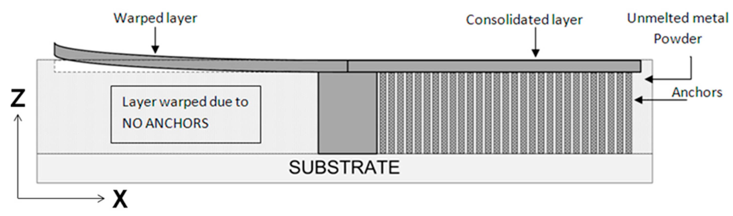
Often metallic components formed using SLM require support structures or anchors as shown in
Figure 1. Anchors are metallurgically fused to the substrate plate and various locations across the laser melted component, forcibly holding geometries in place. Anchors are made from the same material as the SLM component and are also formed through the layer by layer melting of powder within the powder bed. Typically large overhanging/unsupported geometries built parallel to the powder bed require the most support/anchoring [
6]. This requirement for anchors/supports restricts the geometric freedom of the process, and increases material/energy utilisation and post processing operations. Because of the limitations anchors exert over the process, efforts to limit the number of supports/anchors and minimise residual stress remains a major research priority today.
1.1. Anchorless Selective Laser Melting
Removing or alleviating stress build up and the requirement for anchors within SLM can be achieved by preventing parts from completely solidifying during processing or maintaining in a stress reduced state. Anchorless Selective Laser Melting (ASLM) or Semi-Solid Processing (SSP) has been developed to prevent processed metal from completely solidifying during an SLM build [
7,
8].
This is achieved by forming a eutectic alloy or eutectic system (hyper/hypo eutectic) from two or more compositionally distinct materials and maintaining the powder bed pre-heating close to the eutectic melting/solidification point of the newly in process formed alloy.
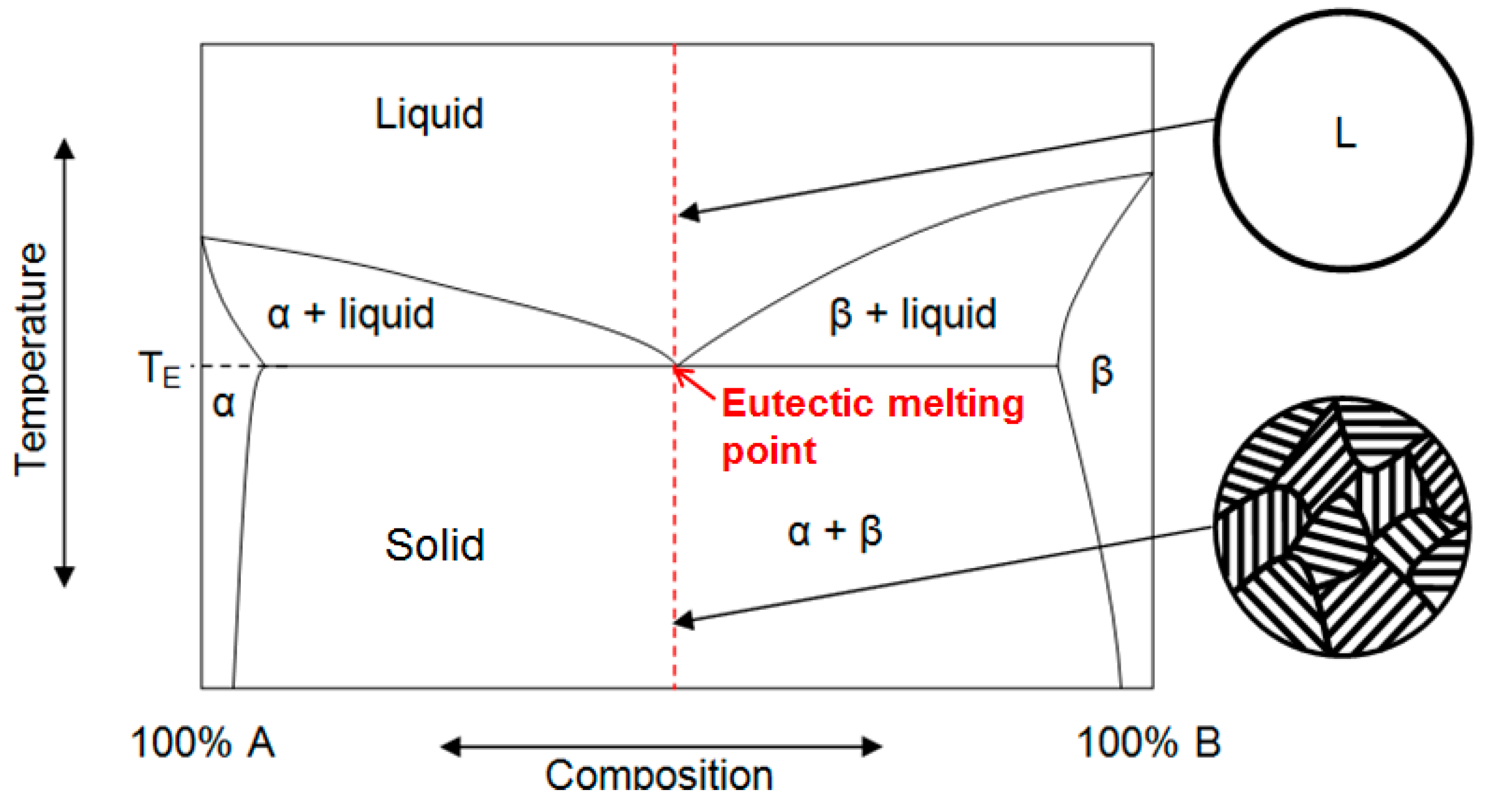
Figure 2 shows a simple binary eutectic phase diagram. Alpha, beta, solid and liquid phases are shown with respect to varying material compositions and temperature; T
E represents the eutectic melting point. Eutectic material proportions can vary from the exact eutectic point creating hypo or hyper eutectic (alloys containing a eutectic system) with variable solidification temperatures and material properties. The range of compositions that have the potential to form eutectics is broad, ranging from aluminium alloys to higher temperature nickels.
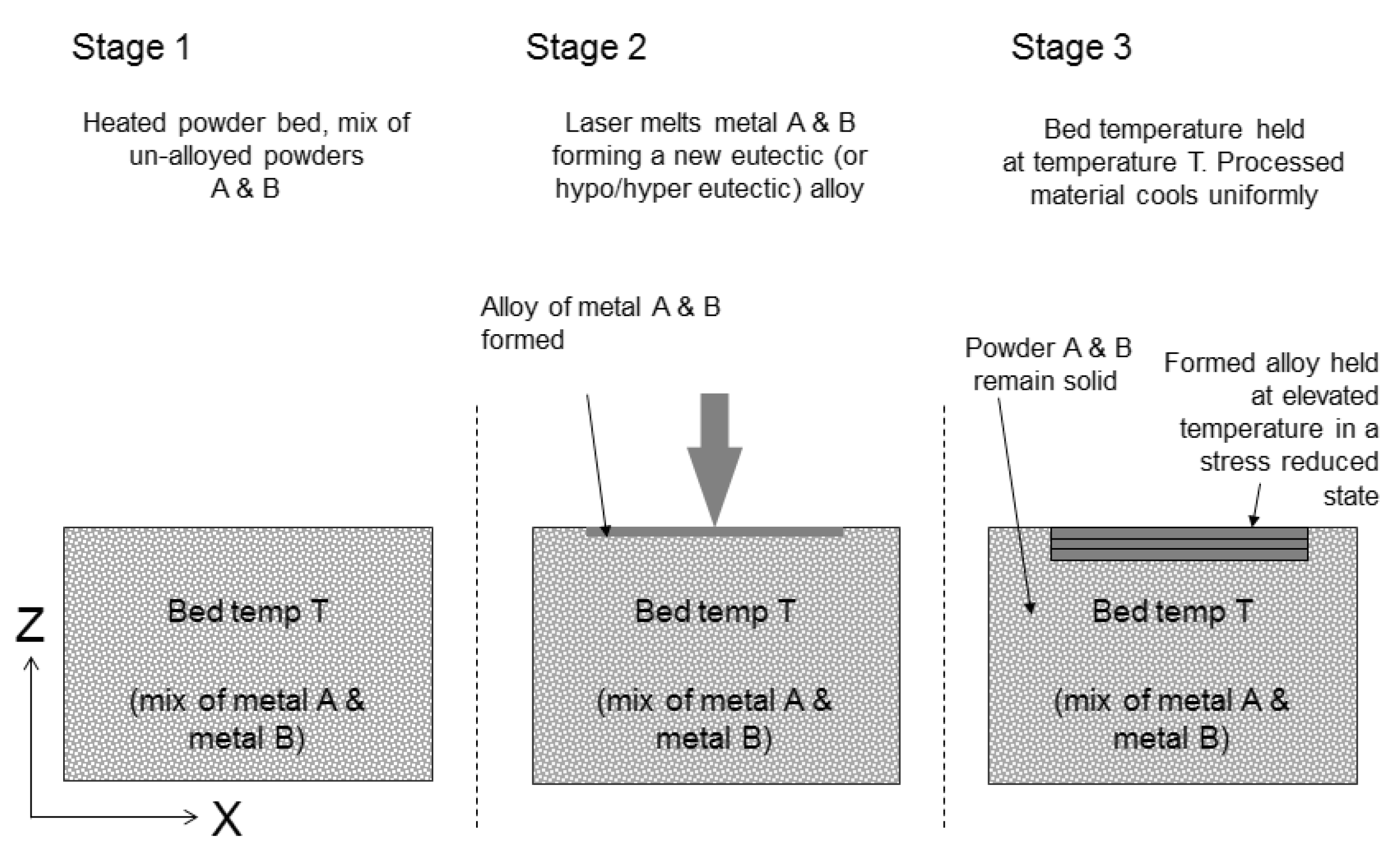
Figure 3 illustrates the ASLM method and its use of eutectic materials. A batch of material A and B powder is mixed in their un-alloyed eutectic proportions. These materials are then deposited during the ASLM process while maintaining the bed temperature near the eutectic point of the alloy but less than the melt temperature of the individual un-alloyed powder (to prevent melting and agglomeration of un-processed feedstock). It may still be possible to pre-heat the powder bed to temperatures below the eutectic melt point so that stresses are not developed or are sufficiently relieved. Stresses can be sufficiently relaxed if the bed temperature allows diffusional relaxation of the material [
9]. Dependent on the material, these relaxation kinetics are initiated at between 40% and 60% of the solidification temperature of the material; this is also time dependent. When the laser scans regions of the powder bed, the individual powders A and B will melt and form a eutectic alloy in-situ; this forms a new solidification temperature that will now only solidify at temperatures below the eutectic solidification point. Since the bed temperature is set near the eutectic point, the melted/alloyed regions will not rapidly solidify or if they are within the diffusional temperature range, they will generate less residual stress than those formed during conventional SLM (rapid melting/solidification rates). Eutectic compositions such as Al66Mg offer large processing windows of 212 °C (temperature difference between eutectic melt point and lowest melting point of individual un-alloyed material). A large processing window may be advantageous as the bed temperature control would not need to be regulated as precisely compared to that of a small processing window. Furthermore, a large processing window may reduce unwanted solid state sintering of unprocessed powders due to pre-heat temperature being far lower than the melt temperature of the un-alloyed material. This solid state sintering or “caking” of material can cause material deposition issues due to powder agglomeration.
1.2. Custom Alloy Feedstocks and In-Situ Alloying
The composition of powders used as SLM feedstock are often based upon standard alloys used in conventional manufacturing processes (e.g., casting). These material alloy systems are designed for the application and manufacturing process used. Sourcing custom gas atomised powder feedstock for SLM processing is costly and can inhibit the experimental development of new alloys. Alternative material development methods are typically required to build confidence in a material’s process ability/properties before investing in the full scale manufacture of a new alloy powder. This typically would be done by melting batch elements in a furnace under controlled conditions, producing a billet requiring further analysis. Customisation of powders can be used to improve processing ability of materials using SLM or Electron Beam Melting (EBM) technologies. Elemental powder blends and Metal Matrix Composites (MMC) have been processed using SLM technology [
10,
11,
12]. This has enabled a faster, more cost-effective development of new powder feedstock.
Bartkowiak et al. [
13] demonstrated the use of elemental mixtures of Al-Cu powder as feedstock material for the SLM process. The utilisation of elemental mixtures demonstrated a cost-effective approach towards the designing of powder feedstock prior to committing to procure/manufacture new designed powders for research study. In this approach, elemental powder elements were mixed in desired weight percentage and processed under a laser forming an alloy in-situ. In-situ alloying of binary alloys using the copper titanium alloy system (TiCu28) [
11]. The purpose of the study was to identify processing parameters for alloying binary alloy systems. The single line tracks melted indicated in-situ alloying of material to a maximum density of 84%. However, it was suggested that the oxidation during melting inhibited densification of melt tracks; the oxygen trapped in the powder feedstock was a primary source of oxidation. This is very common in feedstock powders and therefore, low oxygen content quality powders are often required to overcome this issue. In-situ alloying of elemental/alloy blends is required for the ASLM process to maintain process material in a semi-solid or stress-reduced state, SLM in-situ alloying with blends incorporating Bi-Zn, Al-Si and Ti-Cu have been successfully attempted [
7,
8,
14].
2. Al339 Alloy and Design
The powder feedstock used in conventional SLM would typically be processed in a pre-alloyed state. ASLM requires feedstock to contain at least two components with differing chemical compositions with individually higher melting temperatures compared to their combined/alloys eutectic solidification temperature.
3XX series aluminium casting alloys have been popular for use in industry due to their physical properties and superior cast-ability. They are used widely for applications within automobile, aerospace and medical industries [
15]. A screening activity was performed on various aluminium alloys system and aluminium alloy-Al339 was identified as a suitable candidate material due it having a similar Si content to eutectic alloys successfully processed using ASLM.
The design of feedstock material for ASLM processing required the Al339 alloy to be separated into two blends in order to reduce the overlap melting and solidification temperature; i.e., the introduction of super-cooling of material at solidification. This super-cooling behaviour of material is very common in polymer AM [
8,
16]. This was primarily done by separating elements responsible for eutectic solidification and placing them into separate alloys. A series of combinations (recipes) were formulated and studied for factors such as number of elements in a single alloy, number of pre-alloyed powder batches, mixing ratio, and the processing window generated. The processing window is the difference between the lowest melting temperature of any of the un-alloyed batches within the feedstock used in the blend and the solidification temperature of in-situ alloyed material after processing.
Based on numerous iterations within Thermo-Calc (Version 1.6), the alloy combination with the largest processing window was used. Al339 alloy was split into two pre-alloyed batches, Al-Mg and Si-Cu-Ni. The mixing ratio for Alloy A:Alloy B was 84.75:15.25; this was approximated to 85:15. The composition of the two pre-alloyed batches are shown in
Table 1. Individually, alloy A and alloy B do not constitute an Al339 alloy, however, when weighted/mixed in specified proportions (alloy A + alloy B) and fully alloyed together under the action of the laser, they will form the Al339 alloy. The processing window is the difference between the lowest solidus temperature of the powder batch (alloy A or B) and the solidus temperature of the alloy.
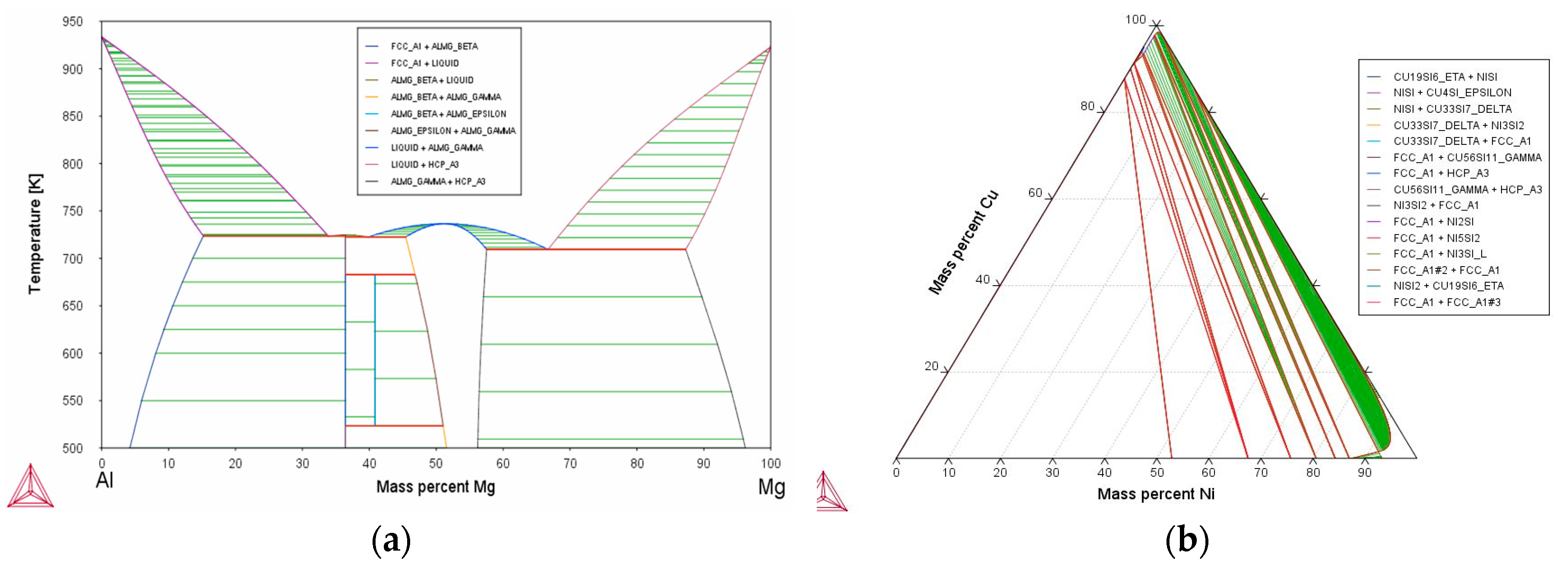
In conjunction with theoretical modelling, Thermo-Calc was used to identify some of the key properties of alloy chemistry that assisted in calculating the processing window and also enabled the identification of theoretical phases in the designed alloy (shown in
Figure 4).
3. Experimental Procedure
3.1. SLM Processing and Optimisation
A Renishaw SLM 125 system with a 200W fibre laser was used for this study. The scan speed of the laser was derived from point distance (µm, linear distance between two laser exposure spots) and exposure time (µs, duration of exposure of laser spot). The process chamber was fitted with a 125 mm × 125 mm × 100 mm build volume as is standard. However, for this study, a custom high temperature substrate heater was designed and integrated into the SLM 125 system. The designed bed was capable of heating the powder bed up to 380 °C, but in doing so it also reduced the build volume size to Ø 50 mm × 40 mm.
Process parameter optimization for blends of powders was undertaken at three bed temperatures: room temperature, 100 °C and 380 °C. For this, a series of cubes 5 mm × 5 mm × 5 mm were produced and analysed for density. For high throughput, the laser power was set at a maximum of 200 W and parameters such as point distance, exposure time and hatch spacing were altered; a layer thickness of 40 µm was used. Laser Energy Density (ED) is the total energy inputted by the laser onto the powder bed to melt the powder and is a function of laser power (W), relative scan speed (mm/s) and hatch spacing. For heated bed trials, prior to processing at higher temperatures, the powder bed was allowed to soak in heat for 30 min.
3.2. Powder Preparation and Mixing
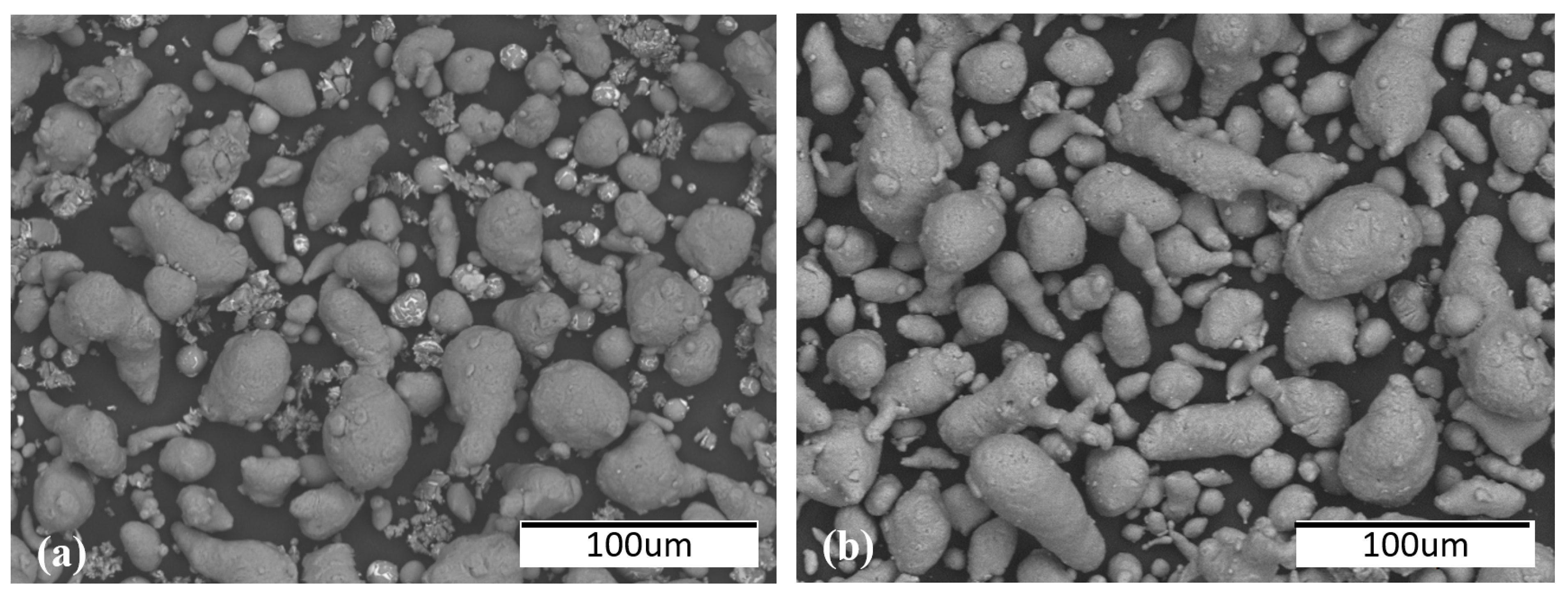
Gas atomised custom designed alloy powders (A and B) and a Al339 pre-alloyed powder in the range of 15 µm to 45 µm were procured for this study. The powder morphology is shown in
Figure 5 for both the blended (alloys A and B) and pre-alloyed Al339 powder. The powder particle size distribution was controlled by sieving the virgin powder using a 63 µm sieve. This resulted in improved control over powder particle size distribution and improved flowability during deposition. To formulate the correct blend of feedstock powder for in-situ alloy of alloy A + B, the powders were weighed and placed in a container with mixing media. A planetary mixer (Speed mixer DAC 800) was used to blend powder batches up to 700 g. The mixer was capable of mixing powder blends at a variable speed of 800–1950 rpm for 5 s to 10 min. The powder blend was mixed at 1000 rpm for three cycles of 2 min each. Zirconia mixing balls of various sizes (large, medium and small) were used as a mixing aid to break the agglomeration of powder and thus enabled effective powder mixing.
3.3. Sample Analysis
The processed samples were cut across the XZ plane (vertically) for microstructural analysis. The samples were processed in accordance to ASTM standard E407-07. Optical and electron microscopy were carried out on the mounted/polished samples to analyse the density and microstructure of consolidated material. Nikon light optical microscopes were used to capture images and the software ImageJ (Version 1.6) was used to measure the density/porosity of parts. An electron microscope was used to observe the microstructure of the samples and phase composition analysis was performed using Siemens D-5000 X-Ray Diffraction (XRD).
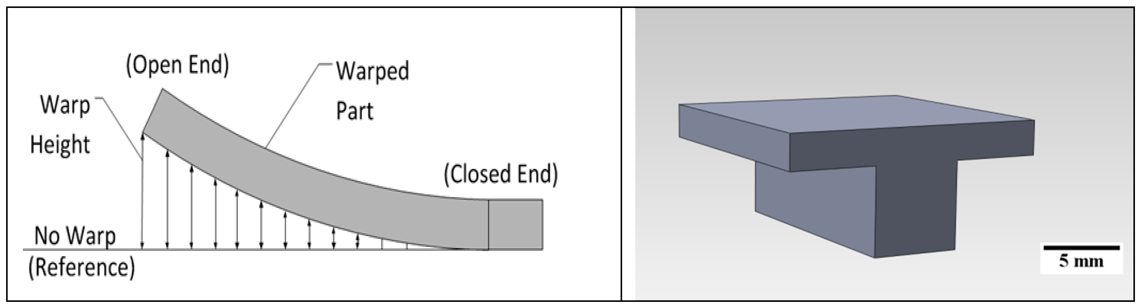
As a measure of ASLM stress reduction capability, a warp measurement was carried out on “T” shaped test samples built as part of this study. The sample design was chosen due to the requirement for adding supports to overhanging surfaces during conventional SLM processing; measuring geometric distortion is an efficient methodology for quickly quantifying the level of residual stress within SLM components [
14,
17]. As the scanning laser processes and melts the powder, the top surface will then cool and shrink; this causes the layer to warp (curl) upwards during the consolidation process. An optical method was employed to measure part distortion. The part would be captured optically (Olympus optical microscope) and images were analysed using Omnimet software to measure warp, as shown in
Figure 6. Software was calibrated using scale bars. The warp measurement was expressed in linear distance between horizontal baselines to the most extreme point of a warp surface.
4. Results
4.1. Parameter Optimisation
Processing parameter optimisation was carried out at room temperature for blended powders (Alloy A + Alloy B) (100 °C and 380 °C bed temperatures for blended powder using a maximum laser power of 200 W and variable laser exposure time and point distance).
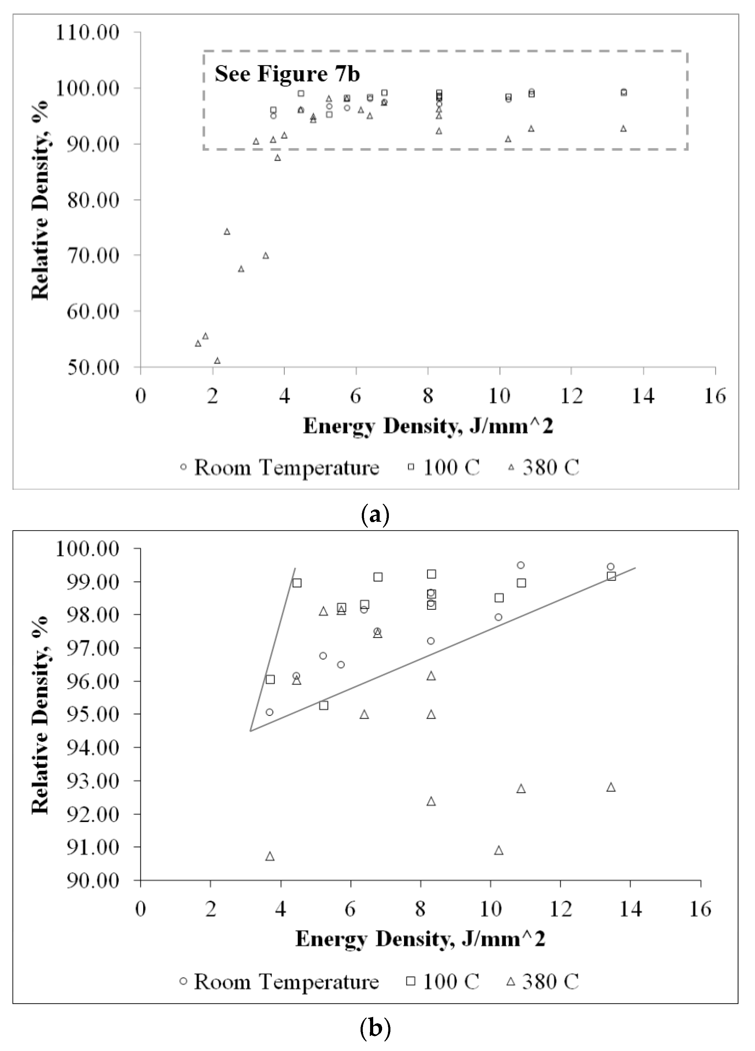
Figure 7a shows the relative density of blended powder fabricated samples as a function of Energy Density (ED) in J/mm
2. At room temperature, a maximum density of 99.5% was obtained using a blended powder mixture. As bed temperature increased, the energy required to transform solid powder into liquid and thus consolidate material reduced. As expected, the ED has an inverse relationship to bed temperature.
Figure 7b shows a reduction in ED to achieve approximately 99% density at a 380 °C bed temperature. It also reveals that excessive energy inputted to melt the powder bed results in evaporation of material causing additional porosity within the processed material. At a bed temperature of 380 °C, an ED higher than 8.2 J/mm
2 resulted in a relative density of samples that were lower than 95%. A relative density of 98.5% was achieved at 5.64 J/mm
2 at 380 °C. While processing at room temperature or an elevated temperature of 100 °C, the ED requirement was very similar. This suggests that bed temperature had no significant effect at 100 °C. It was also noticed that the ED required to process Al339 at 380 °C was almost half of that required at room temperature. These findings suggest that, as expected, the energy input should be less while processing with the assistance of a heated bed.
4.2. Microstructural and Chemical Analysis
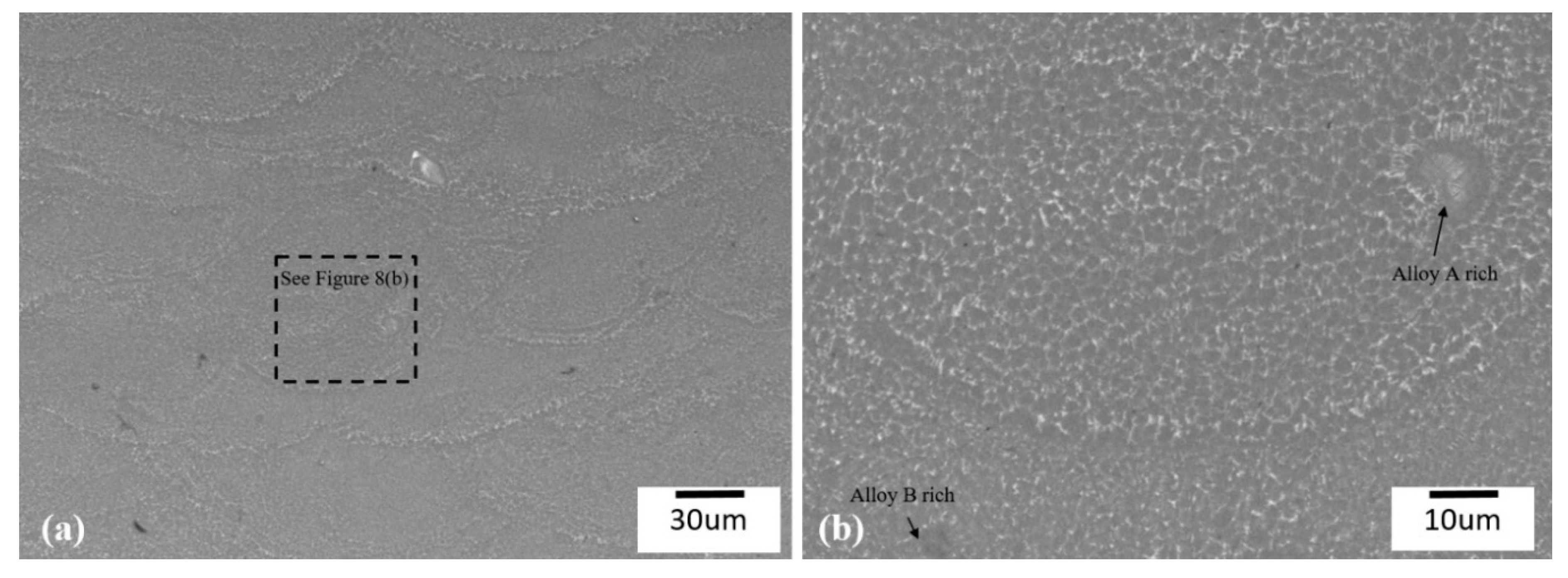
Figure 8 shows SEM images of ASLM processed alloy A + B blended feedstock material (forming Al339 in-situ). The fine distribution of the aluminium solid solution and other intermetallic compounds across the melt pool suggested rapid cooling of the material. The primary microstructure observed was α-Al in the form of dendrites and Al-Si eutectics. Upon further magnification, the direction of dendrites suggested the presence of directional solidification that is typical of metal AM microstructures. The melt pools observed in
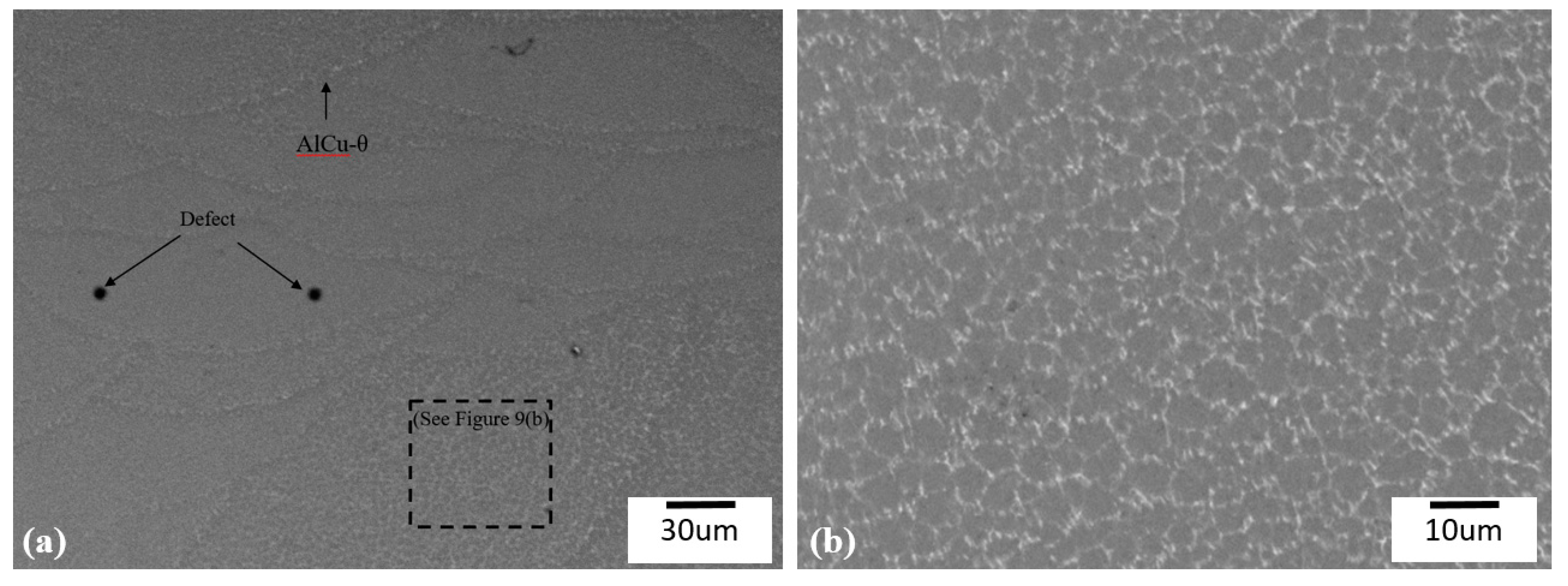
Figure 8 are of different sizes as the laser scan pattern used was a continuous raster scan rotating at 67 deg. The AlCu-θ phase appears to have precipitated around the melt pool boundary, suggesting fine precipitation and solidification at the end. Furthermore, aluminium rich and depleted regions are observed within the same microstructure. This suggested the mixing of powder was relatively uniform with some agglomerations. It is believed that due to the nature of the powder processing (powder blending to layering on powder bed), there would be segregation within the blend that reduces the uniformity of powder feedstock mixing while processing. The microstructure of pre-alloyed Al339 powder processed under the same SLM conditions as the blended powder (100 °C) is shown in
Figure 9.
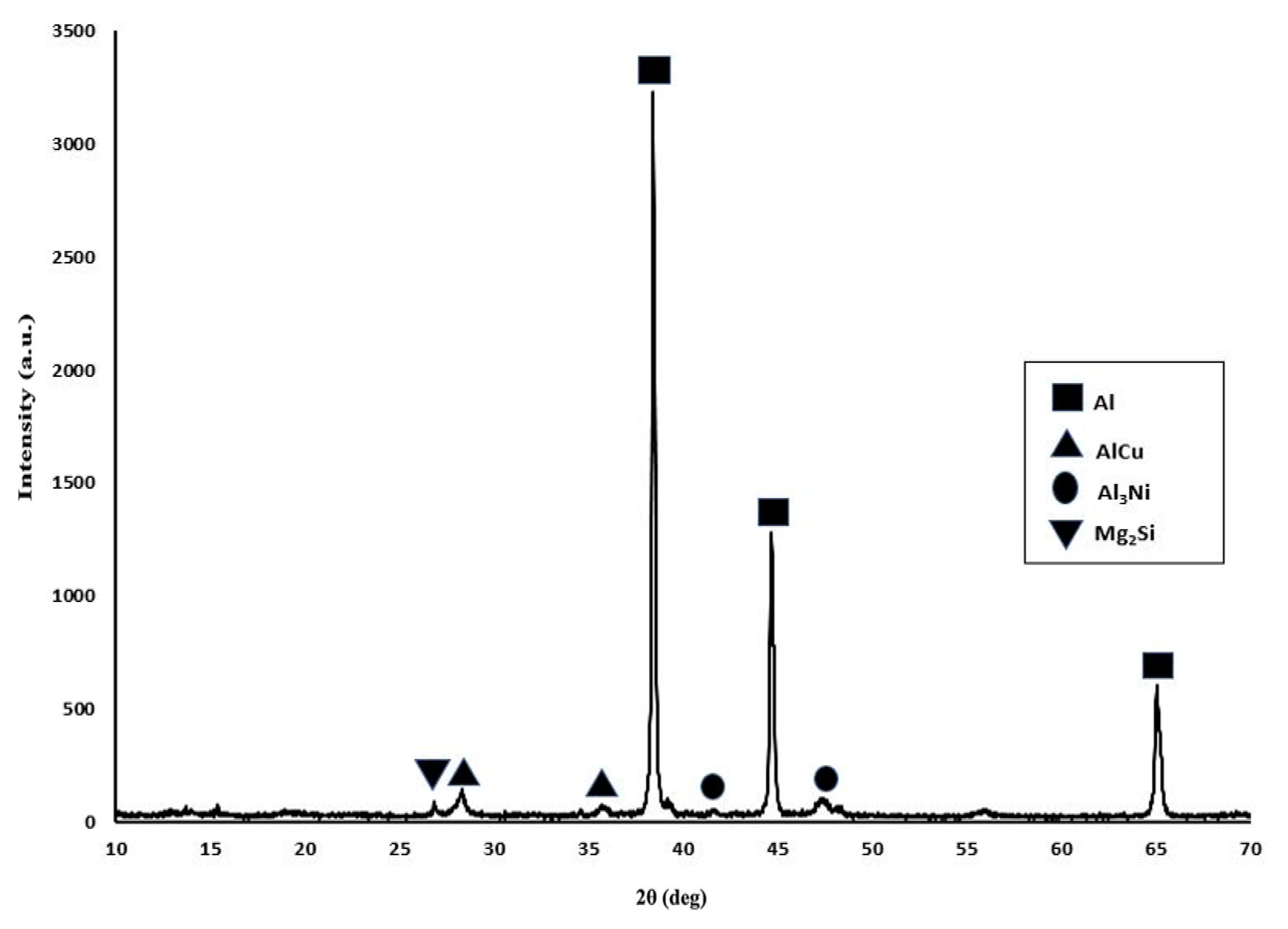
Figure 10 shows the microstructure of A + B blended feedstock material (forming Al339 in-situ) at an elevated bed temperature of 380 °C. The processed sample was allowed to cool from 380 °C to room temperature over 3–4 h. The slower cooling resulted in reticular network of α-Al solid solution. In
Figure 10, the eutectics structures are denoted by the dark grey areas, the primary constituent of Al339. However, the intermetallic structures are potentially concentrated in the interdendritic spaces; alloy B rich regions are in light grey. In the blended SLM samples, intermetallic phases of AlCu-θ, Al
3Ni, and Mg
2Si are present in minor quantities due to the low composition of the elements, as shown in
Figure 11. Directly processing Al339 pre-alloyed powder at 380 °C was not possible due to powder deposition issues (agglomeration of powders due to high powder bed pre-heating; this is discussed further in
Section 4.3).
4.3. Residual Stress Measurement
In this study, the residual stress measurement was undertaken by measuring geometric distortion of the fabricated un-supported overhang geometries (shown in
Figure 6).
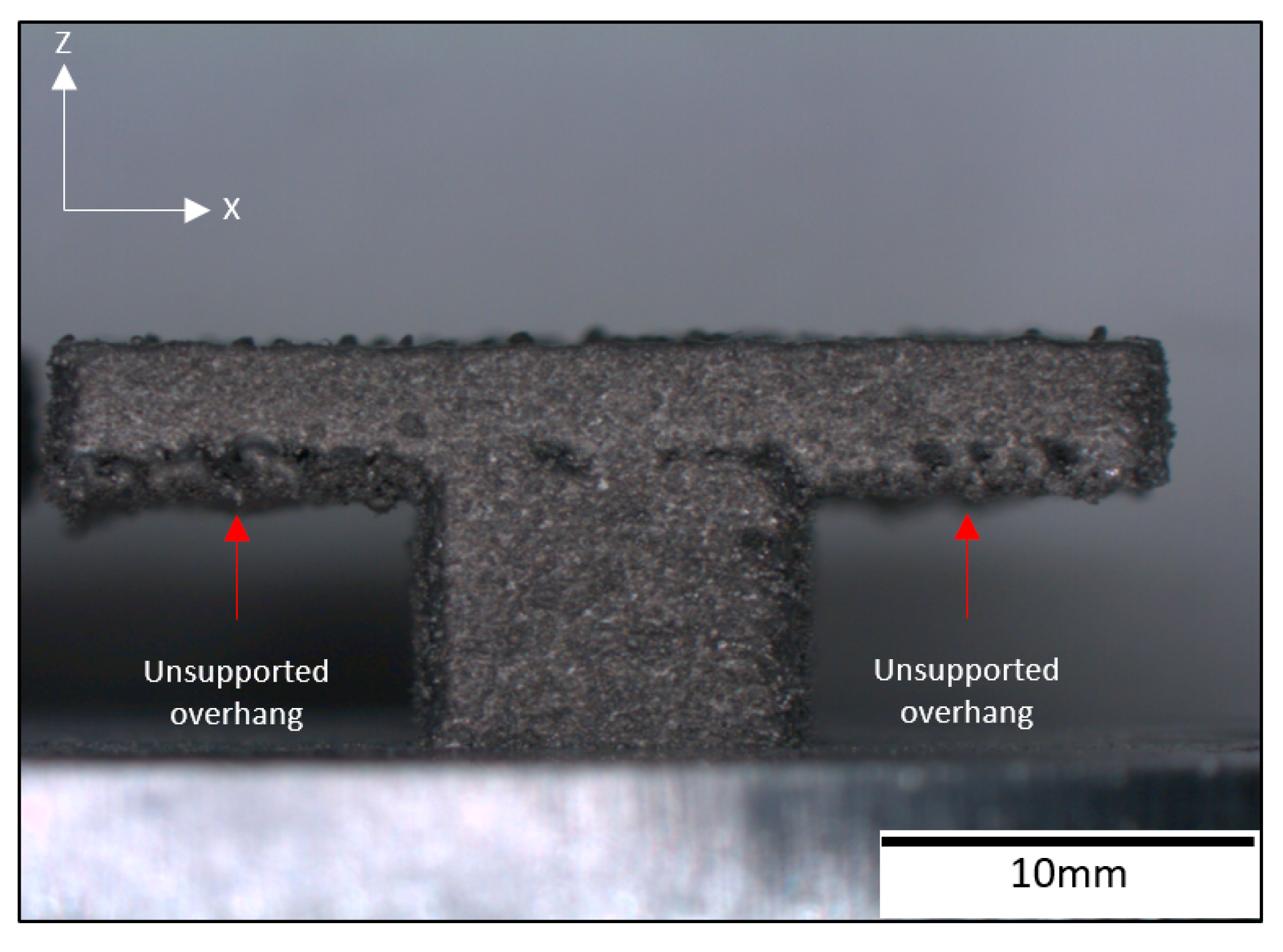
Figure 12 shows the test sample produced using ASLM with two unsupported overhangs. The underside of the overhanging section had satellites formation (not fully melted powder particles attached) increasing surface roughness. An optimisation of the lower skin parameters at a later stage may enable a reduction in satellite formation. The warp observed with this sample was less than 0.1 mm across its 10 mm length and not significant enough to cause builds to fail. It was only possible to successfully produce this geometry at a 380 °C bed temperature. Attempts were made to build this component at lower temperatures (i.e., room temperature and 100 °C), but there was a failure to produce parts due to excessive warpage causing the powder depositor to collide with the sample during processing. Benchmarking studies have been undertaken using similar geometries to determine the maximum unsupported overhang possible using conventional SLM processing of aluminium alloys with similar Si content [
14]. It was found that overhangs of no more than 2 mm could be built before significant warpage would occur. It was also found that attempting to directly process pre-alloyed powders at elevated temperatures (380 °C) to produce the overhang component shown in
Figure 12 resulted in partial agglomeration of powder particles during deposition (specifically around the larger cross-sections of the overhang structure; this is possibly due to increased heat build-up). This made it difficult to consistently deposit material due to a partial sintering or caking of unprocessed powders leading to build failures. Such problems did not exist with processing of the 5 x 5 mm cubes with blends or pre-alloyed powders due to the smaller surface area processed and a lower heat build-up within the powder bed. The processing of powder blends suffered less from powder agglomeration due to higher melt temperatures compared to the pre-alloy Al339 (alloy A-628 °C alloy B-798 °C and pre-alloyed Al339-577 °C). Issues associated with agglomeration of pre-heated pre-alloyed powders has been experienced in other ASLM work [
8].
Studies have shown an inverse relationship between elevated bed temperature and residual stress. By increasing the bed pre-heat temperature, the temperature gradient reduces between the melt-pool and the solidified material leading to a reduction in residual stress build up [
18]. The bed temperature used within this study is lower than the solidification temperature of the newly formed alloy (380 °C and 577 °C, respectively). However, during ASLM, the input from the laser locally heats powder surrounding the melt pool which increases the powder bed temperature. This combined with the 380 °C substrate pre-heating would have allowed the processed materials to be held within a semi-solid state for a prolonged period before solidifying compared with a standard SLM process [
19]. Additionally the powder bed is maintained within the materials diffusional temperature range (annealing temperature) which in turn promotes a relaxation of stresses, such that significant geometric distortion would not occur [
8].
5. Conclusions
This work designed and processed two pre-alloyed batch blends, AlMg and SiCuNi, to create an Al339 alloy in-situ using ASLM. ASLM processing was able to sufficiently reduce residual stresses developed within overhang geometries, allowing them to be manufactured without anchors/supports.
The process parameter optimisation study for the designed Al339 blended feedstock material was performed at increasing bed temperatures. The influence of bed temperature was marginal up to 100 °C but was more significant at an elevated temperature of 380 °C. The required laser energy density required to melt the material was reduced by approximately half (5.64 J/mm2) at 380 °C bed temperatures. Processing alloy A(AlMg) + B(SiCuNi) blended powders at 380 °C enabled the production of un-supported overhanging geometries from a complex alloy system. The observed microstructure of in-situ alloyed samples in comparison to pre-alloyed Al339 displayed similarities, however, the in-situ alloyed samples had aluminium rich and depleted regions within the analysed regions, suggesting that segregation in the powder feedstock may have arisen. It is believed this may have occurred due to the method by which powder is deposited when layering of powder on a build plate. However, this segregation was observed to be minimal. Upon analysing overhang geometries made with in-situ alloyed feedstock, overhangs up to 10 mm could be fabricated with less than 0.1 mm geometric distortion as a result of reduced residual stress when using elevated build temperatures. The capability of restructuring a complex aluminium alloy system such as Al339 (Al-Si-Cu-Mg-Ni) by designing pre-alloyed batches of material that later result in a parent alloy when melted under a laser has been demonstrated and opens up the potential for small scale development of new alloys.
Acknowledgments
The authors would like to thank EPSRC for their support during this research (grant number EP/I028331/1).
Author Contributions
Pratik Vora and Rafael Martinez undertook experiments, analysis and contributed to the writing of this work. Iain Todd, Neil Hopkinson and Kamran Mumtaz supervised this investigation and contributed to the writing of this work.
Conflicts of Interest
The authors declare no conflict of interest.
References
- Mercelis, P.; Kruth, J.P. Residual stresses in selective laser sintering and selective laser melting. Rapid Prototyp. J. 2006, 12, 254–265. [Google Scholar] [CrossRef]
- Sochalski-Kolbus, L.M.; Payzant, E.A.; Cornwell, P.A.; Watkins, T.R.; Babu, S.S.; Dehoff, R.R.; Lorenz, M.; Ovchinnikova, O.; Duty, C. Comparison of Residual Stresses in Inconel 718 Simple Parts Made by Electron Beam Melting and Direct Laser Metal Sintering. Metall. Mater. Trans. A 2015, 46, 1419–1432. [Google Scholar] [CrossRef]
- Chou, Y.S.; Cooper, K. Systems and Methods for Designing And Fabricating Contact-Free Support Structures for Overhang Geometries of Parts in Powder-Bed Metal Additive Manufacturing. U.S. Patent 14/276.345, 13 November 2014. [Google Scholar]
- Mertens, R.; Clijsters, S.; Kempen, K.; Kruth, J.-P. Optimization of Scan Strategies in Selective Laser Melting of Aluminum Parts With Downfacing Areas. J. Manuf. Sci. Eng. 2014, 136. [Google Scholar] [CrossRef]
- Kruth, J.-P.; Deckers, J.; Yasa, E.; Wauthlé, R. Assessing and comparing influencing factors of residual stresses in selective laser melting using a novel analysis method. Proc. Inst. Mech. Eng. Part B J. Eng. Manuf. 2012, 226, 980–991. [Google Scholar] [CrossRef]
- Vandenbroucke, B.; Kruth, J.P. Selective laser melting of biocompatible metals for rapid manufacturing of medical parts. Rapid Prototyp. J. 2007, 13, 196–203. [Google Scholar] [CrossRef]
- Mumtaz, K.; Vora, P.; Hopkinson, N. A method to eliminate anchors/supports from directly laser melted metal powder bed processes. In Proceedings of the Solid Freeform Fabrication, Austin, TX, USA, 8–10 August 2011. [Google Scholar]
- Vora, P.; Mumtaz, K.; Todd, I.; Hopkinson, N. AlSi12 in-situ alloy formation and residual stress reduction using anchorless selective laser melting. Addit. Manuf. 2015, 7, 12–19. [Google Scholar] [CrossRef]
- Onaka, S.; Okada, T.; Kato, M. Relaxation kinetics and relaxed stresses caused by interface diffusion around spheroidal inclusions. Acta Metall. Mater. 1991, 39, 971–978. [Google Scholar] [CrossRef]
- Kühnle, T.; Partes, K. In-Situ Formation of Titanium Boride and Titanium Carbide by Selective Laser Melting. Phys. Procedia 2012, 39, 432–438. [Google Scholar] [CrossRef]
- Sanz-Guerrero, J.; Ramos-Grez, J. Effect of total applied energy density on the densification of copper–titanium slabs produced by a DMLF process. J. Mater. Proc. Technol. 2008, 202, 339–346. [Google Scholar] [CrossRef]
- Attar, H.; Bönisch, M.; Calin, M.; Zhang, L.-C.; Scudino, S.; Eckert, J. Selective laser melting of in situ titanium–titanium boride composites: Processing, microstructure and mechanical properties. Acta Mater. 2014, 76, 13–22. [Google Scholar] [CrossRef]
- Bartkowiak, K.; Ullrich, S.; Frick, T.; Schmidt, M. New Developments of Laser Processing Aluminium Alloys via Additive Manufacturing Technique. Phys. Procedia 2011, 12, 393–401. [Google Scholar] [CrossRef]
- Mumtaz, K.; Hopkinson, N.; Stapleton, D.; Todd, I.; Derguti, F.; Vora, P. Benchmarking metal powder bed Additive Manufacturing processes (SLM and EBM) to build flat overhanging geometries without supports. In Proceedings of the Solid Freeform Fabrication Symposium, Austin, TX, USA, 6–8 August 2012. [Google Scholar]
- Baker, H.; Okamoto, H. Alloy Phase Diagrams. In ASM Handbook; ASM International: Materials Park, OH, USA, 1992; Volume 3. [Google Scholar]
- Kruth, J.P.; Levy, G.; Schindel, R.; Craeghs, T.; Yasa, E. Consolidation of polymer powders by selective laser sintering. In Proceedings of the International Conference on Polymers and Moulds Innovations, Gent, Belgium, 17–19 September 2008; pp. 15–30. [Google Scholar]
- Yadroitsava, I.; Grewar, S.; Hattingh, D.; Yadroitsev, I. Residual Stress in Slm Ti6al4v Alloy Specimens. Mater. Sci. Forum 2015, 828, 305–310. [Google Scholar] [CrossRef]
- Ali, H.; Ma, L.; Ghadbeigi, H.; Mumtaz, K. In-situ residual stress reduction, martensitic decomposition and mechanical properties enhancement through high temperature powder bed pre-heating of Selective Laser Melted Ti6Al4V. Mater. Sci. Eng. A 2017, 695, 211–220. [Google Scholar] [CrossRef]
- Brandl, E.; Heckenberger, U.; Holzinger, V.; Buchbinder, D. Additive manufactured AlSi10Mg samples using Selective Laser Melting (SLM): Microstructure, high cycle fatigue, and fracture behavior. Mater. Des. 2012, 34, 159–169. [Google Scholar] [CrossRef]
© 2017 by the authors. Licensee MDPI, Basel, Switzerland. This article is an open access article distributed under the terms and conditions of the Creative Commons Attribution (CC BY) license (http://creativecommons.org/licenses/by/4.0/).


