Improving the Cooling Efficiency of Heat Sinks through the Use of Different Types of Phase Change Materials


Abstract
:1. Introduction
2. Modeling
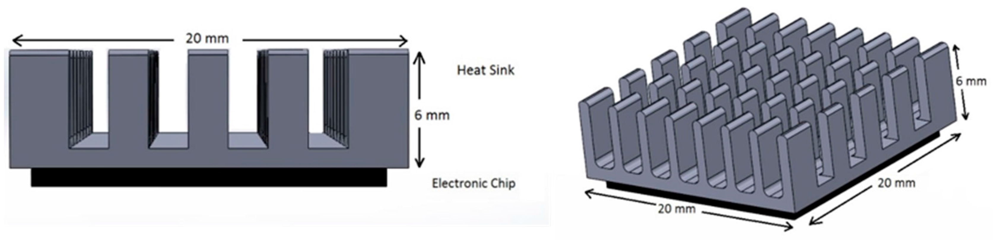
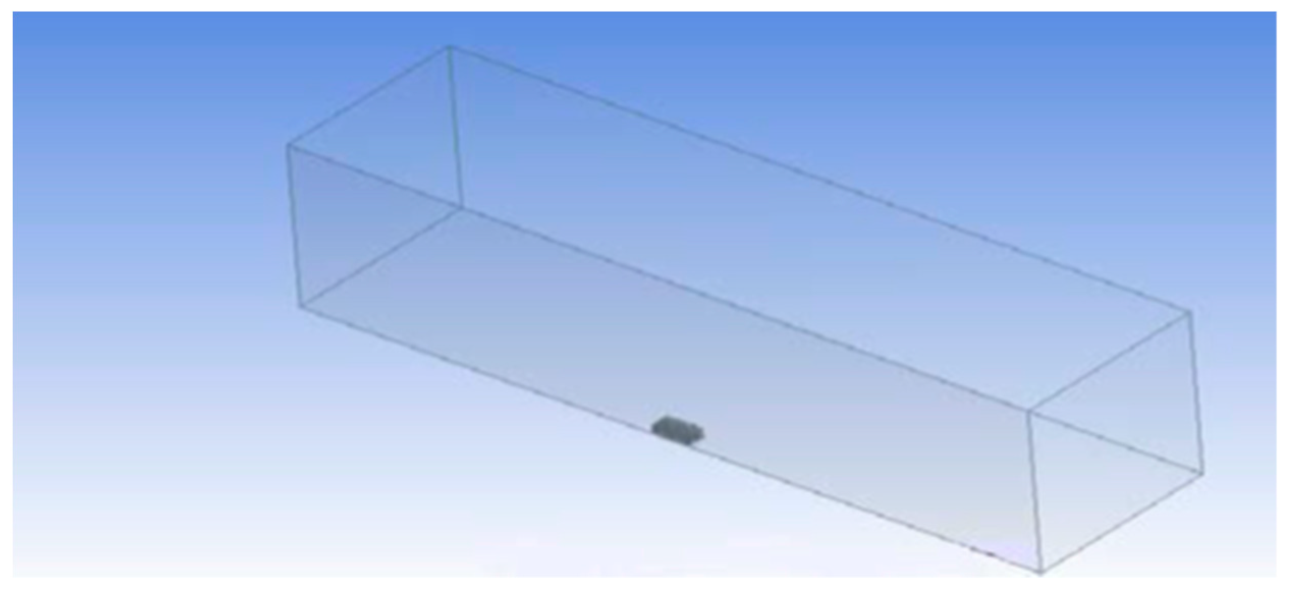
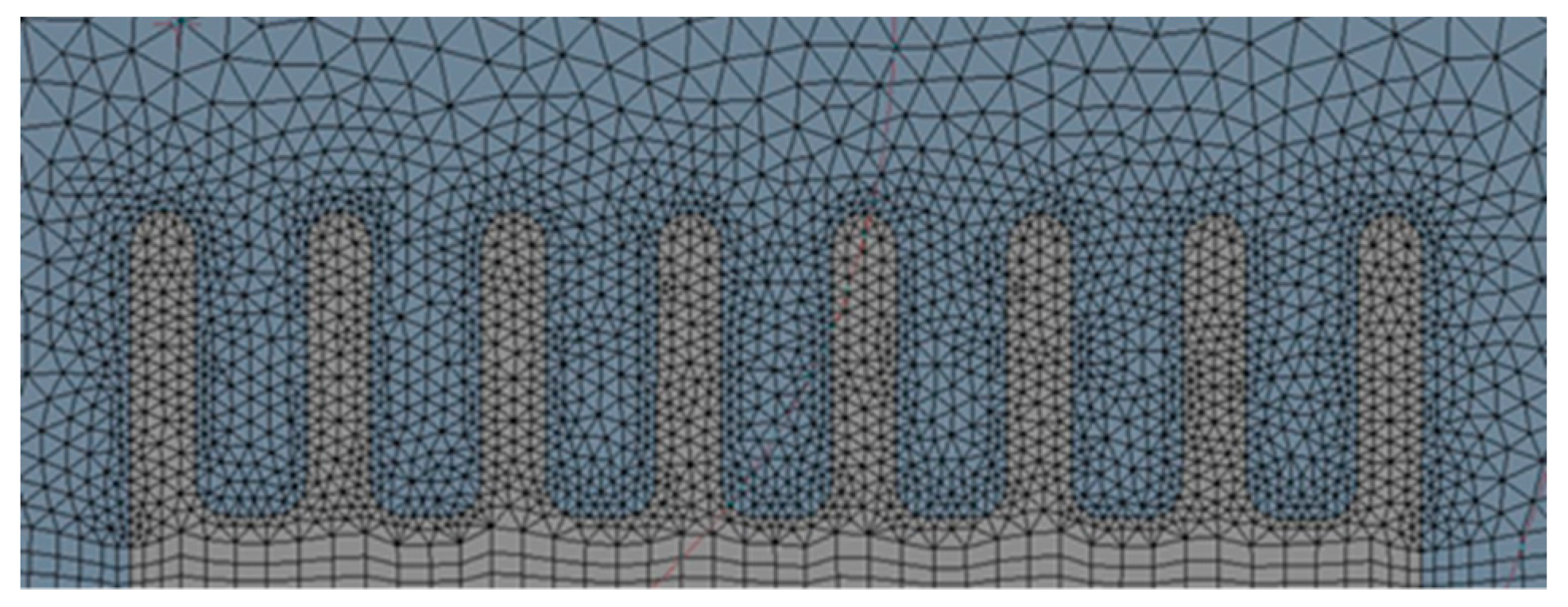
2.1. Domain
2.2. Governing Equations
2.2.1. Heat Transfer
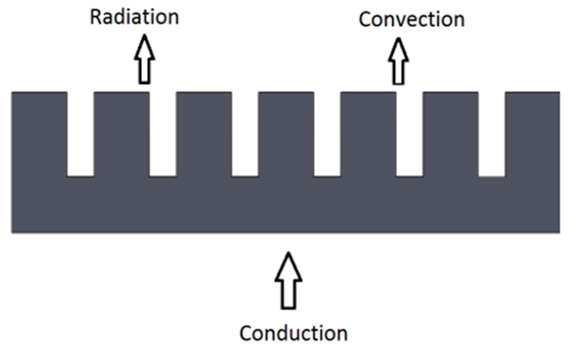
- Conduction: is the transfer of energy from the more energetic to the less energetic particles of the same substance or between two substances in contact due to the interaction between particles. In this case, conduction occurs from the chip to the heat sink [12].where;
- is the heat transfer rate ;
- is the thermal conductivity .
- Convection: is the transfer of energy between the surface of an object and a fluid in motion when both are at different temperatures [12].where;
- is the convective heat transfer coefficient ;
- is the surface temperature (K);
- is the fluid temperature (K).
- Radiation: Thermal radiation is the energy emitted by matter that is at non-zero absolute temperature. The energy of the radiation field is transported by electromagnetic waves [12].where;
- J is the radiosity, the rate at which radiation leaves a surface per unit area ;
- G is the irradiation, the rate at which radiation is incident upon a surface per unit area .
where;- E is the emissive power, the rate at which radiation is emitted from a surface per unit area ;
- is the reflectivity, the fraction of the irradiation on a surface that is reflected.
2.2.2. Phase Change Materials
- , reference enthalpy (J/kg);
- , reference temperature (K).
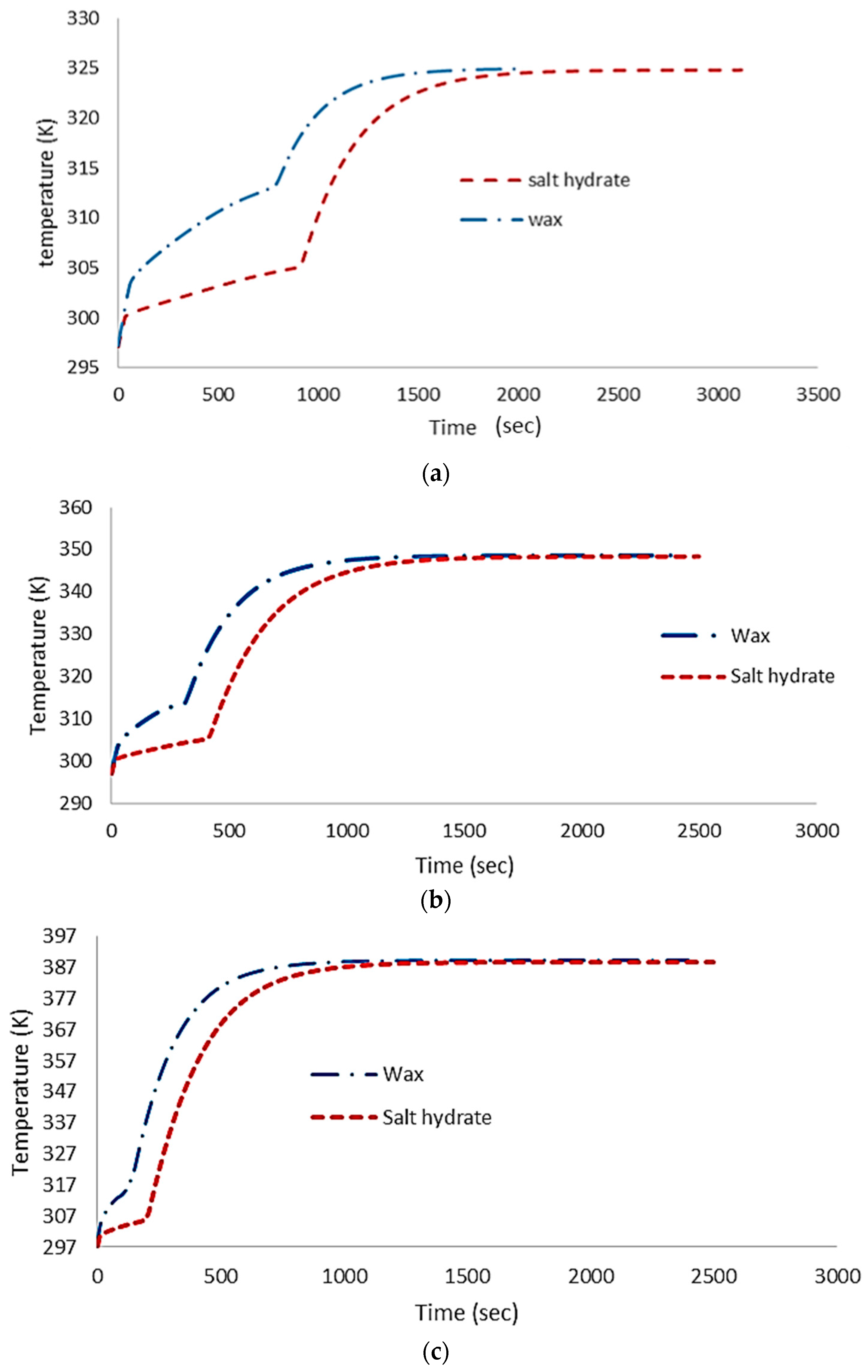
3. PCM Selection
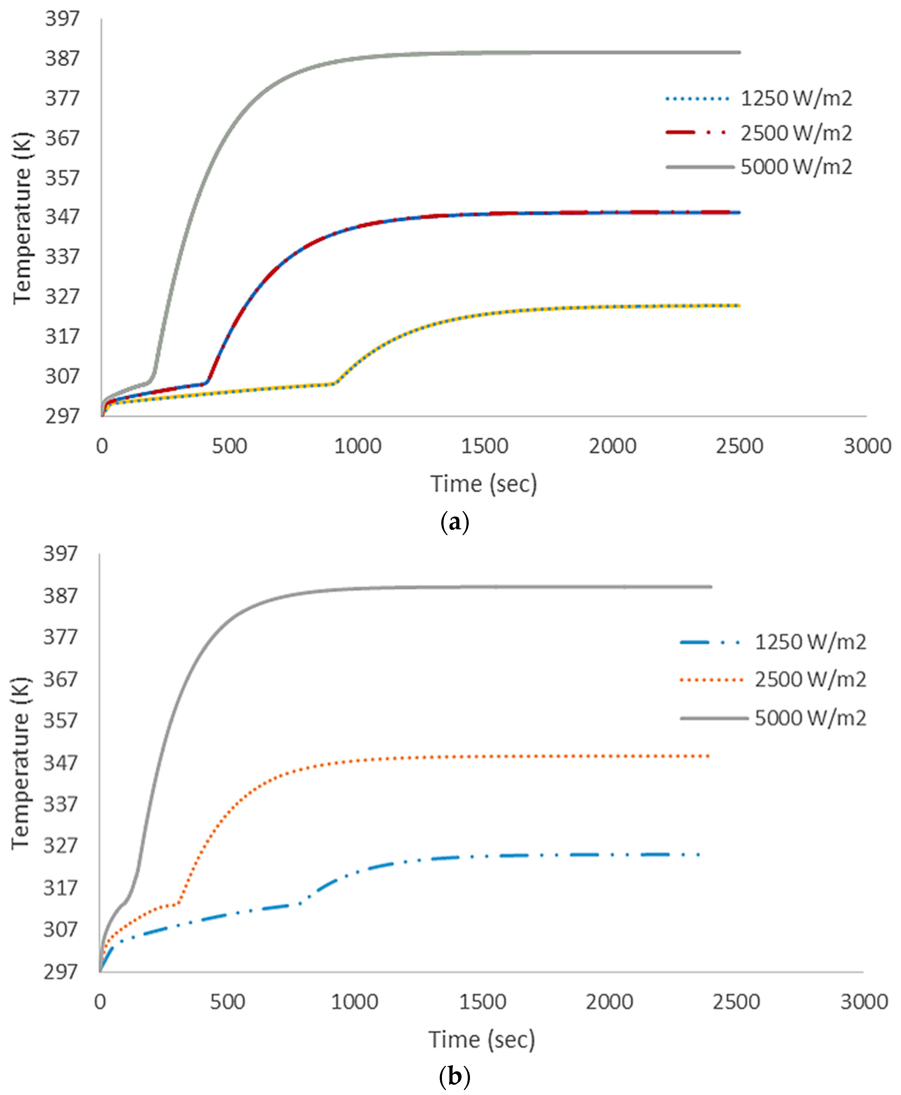
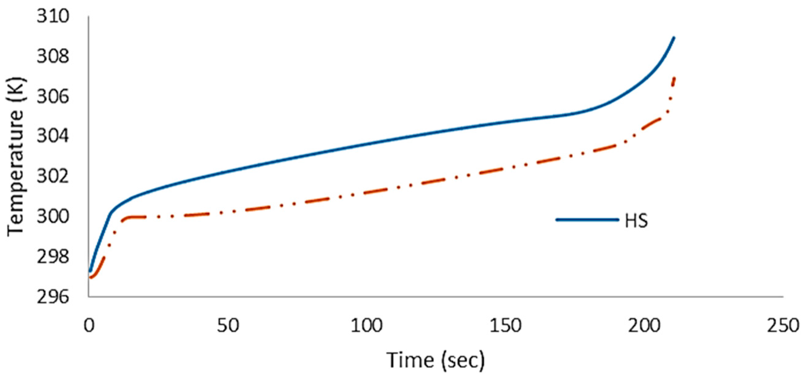
4. Results
4.1. Numerical Results
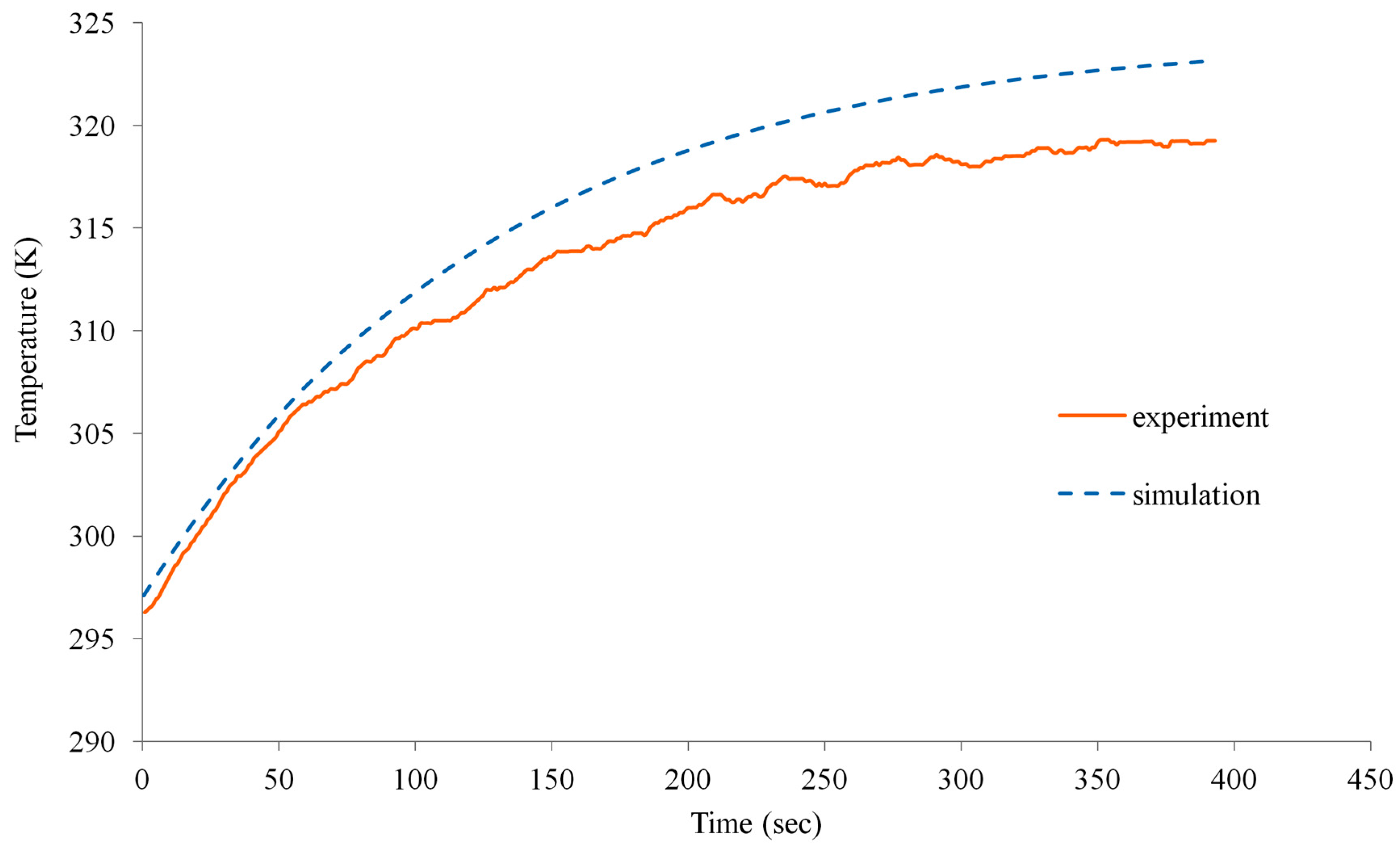
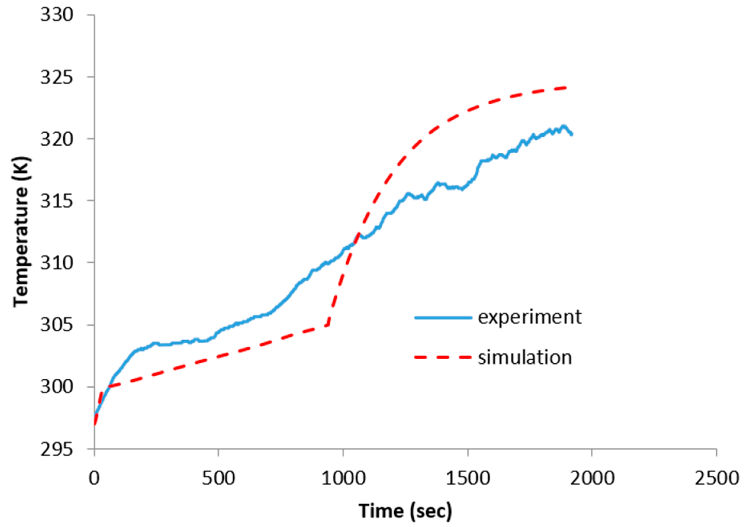
4.2. Experimental Validation
5. Discussion
6. Conclusions
Author Contributions
Conflicts of Interest
References
- Cengel, Y.; Ghajar, A. Heat and Mass Transfer: Fundamentals and Applications, 5th ed.; McGraw-Hill Education: New York, NY, USA, 2015; pp. 1–944. ISBN 9780073398181. [Google Scholar]
- Coskun, A.K.; Atienza, D.; Rosing, T.S.; Brunschwiler, T.; Michel, B. Energy-Efficient Variable-Flow Liquid Cooling in 3D Stacked Architectures. In Proceedings of the Conference on Design, Automation and Test in Europe, Dresden, Germany, 8–12 March 2010; pp. 111–116. [Google Scholar]
- Zalba, B.; Marin, J.M.; Cabeza, L.F.; Mehlin, H. Free-cooling of building with phase change materials. Int. J. Refrig. 2004, 27, 839–849. [Google Scholar] [CrossRef]
- Liu, C.; Rao, Z. Challenges in various thermal energy storage technologies. Sci. Bull. 2017, 62, 231–233. [Google Scholar] [CrossRef]
- Stropnik, R.; Stritih, U. Increasing the efficiency of PV panel with the use of PCM. Renew. Energy 2016, 97, 671–679. [Google Scholar] [CrossRef]
- Lee, D.Y.; Vafai, K. Comparative analysis of jet impingement and microchannel cooling for high heat flux applications. Int. J. Heat Mass Transf. 1999, 42, 1555–1568. [Google Scholar] [CrossRef]
- Lasance, C.J.; Simons, R.E. Advances in high-performance cooling for electronics. Electron. Cool. 2005, 11, 22–39. [Google Scholar]
- Tuckerman, D.B.; Pease, R.F.W. High-performance heat sinking for VLSI. IEEE Electron Device Lett. 1981, 2, 126–129. [Google Scholar] [CrossRef]
- Hasan, A.; Hejase, H.; Abdelbaqi, S.; Assi, A.; Hamdan, M.O. Comparative effectiveness of different phase change materials to improve cooling performance of heat sinks for electronic devices. Appl. Sci. 2016, 6, 226. [Google Scholar] [CrossRef]
- Sharma, A.; Tyagi, V.V.; Chen, C.R.; Buddhi, D. Review on thermal energy storage with phase change materials and applications. Renew. Sustain. Energy Rev. 2009, 13, 318–345. [Google Scholar] [CrossRef]
- Kandasamy, R.; Wang, X.Q.; Mujumdar, A.S. Transient cooling of electronics using phase change material (PCM)-based heat sinks. Appl. Therm. Eng. 2008, 28, 1047–1057. [Google Scholar] [CrossRef]
- Incropera, F.P.; Dewitt, D.P.; Bergman, T.L.; Lavine, A.S. Fundamentals of Heat and Mass Transfer, 6th ed.; John Wiley and Sons: Hoboken, NJ, USA, 2006; ISBN 0470088400. [Google Scholar]
- Assi, I.; Mjallal, I.; Farhat, H.; Hammoud, M.; Ali, S.; AL Shaer, A.; Assi, A. Using Phase Change Material in Heat Sinks to Cool Electronics Devices with Intermittent Usage. In Proceedings of the IEEE 7th International Conference on Power and Energy Systems, Toronto, ON, Canada, 1–3 November 2017; pp. 66–69. [Google Scholar]


| Materials | Salt Hydrate | Wax |
|---|---|---|
| Thermal conductivity | 0.6 | 0.15 |
| Specific heat capacity | 2 | 2.2 |
| Density | 1500 | 820 |
| Viscosity | 0.00184 | 0.00068 |
| Solidus temperature | 27 | 30 |
| liquidus temperature | 32 | 40 |
| Latent heat of fusion | 200 | 190 |
© 2018 by the authors. Licensee MDPI, Basel, Switzerland. This article is an open access article distributed under the terms and conditions of the Creative Commons Attribution (CC BY) license (http://creativecommons.org/licenses/by/4.0/).
Share and Cite
Mjallal, I.; Farhat, H.; Hammoud, M.; Ali, S.; Assi, I. Improving the Cooling Efficiency of Heat Sinks through the Use of Different Types of Phase Change Materials. Technologies 2018, 6, 5. https://0-doi-org.brum.beds.ac.uk/10.3390/technologies6010005
Mjallal I, Farhat H, Hammoud M, Ali S, Assi I. Improving the Cooling Efficiency of Heat Sinks through the Use of Different Types of Phase Change Materials. Technologies. 2018; 6(1):5. https://0-doi-org.brum.beds.ac.uk/10.3390/technologies6010005
Chicago/Turabian StyleMjallal, Ibrahim, Hussien Farhat, Mohammad Hammoud, Samer Ali, and Ibrahim Assi. 2018. "Improving the Cooling Efficiency of Heat Sinks through the Use of Different Types of Phase Change Materials" Technologies 6, no. 1: 5. https://0-doi-org.brum.beds.ac.uk/10.3390/technologies6010005