Article

Effects of the Infill Density on the Mechanical Properties of Nylon Specimens Made by Filament Fused Fabrication

by
Svetlana Terekhina
1,
Innokentiy Skornyakov
2,
Tatiana Tarasova
2 and
Sergei Egorov
2,*
1
Laboratoire Angevin de Mécanique, Procèdes et innovAtion, Ecole Nationale Supérieure d’Art et Métiers, 49100 Angers CEDEX 01, France
2
Laboratory of Innovative Additive Technologies, Moscow State University of Technology “STANKIN”, 127055 Moscow, Russia
*
Author to whom correspondence should be addressed.
Submission received: 30 June 2019 / Revised: 10 August 2019 / Accepted: 13 August 2019 / Published: 16 August 2019
(This article belongs to the Special Issue Reviews and Advances in Materials Processing)

Abstract

:
Additive manufacturing of polymer products over the past decade has become widespread in various areas of industry. Using the fused filament fabrication (FFF) method, one of the most technologically simple methods of additive manufacturing, it is possible to produce parts from a large number of different materials, including wear-resistant nylon. The novelty of the work is properties investigation of ±45° filling configuration with different filling degree for nylon, as well as calculating the effect of infill on the strength characteristics, excluding the shell. This article reflects the process of manufacturing samples from nylon using FFF technology with various internal topologies, as well as tensile tests. The analysis of the obtained results is performed and the relationship between the structure of the sample and the limit of its strength is established. To calculate real filling degree and the effect of internal filling on the strength characteristics of the specimen, it is proposed to use a method based on the geometric and mass parameters. The FFF method is promising for developing methods for producing a composite material. The results of this article can be useful in choosing the necessary manufacturing parameters.

1. Introduction

Rapidly developing for several decades, additive technologies are gradually replacing the classic ways of making products in many industries. This fact is due to the main principle of new methods, the layer-by-layer creation of objects based on digital three-dimensional model controlled by a computer. This approach minimizes the number of equipment and the number of technological operations.
A wide range of materials available for additive production (from metallic powders to polymer filaments) makes it possible to produce analogs of products obtained by classical methods, often not inferior to them by mechanical characteristics. A bright representative of polymer materials used in this kind of production is nylon. Nylon is a thermoplastic polymer belongs to the group of polyamides. These plastics are characterized by high wear resistance but increased hygroscopicity (the ability to absorb moisture). Nylon is used in the production of elements of friction pairs and in the medical industry for the manufacturing of prostheses. Nylon is used to make some parts of machines because it is inexpensive and durable. It is often used in the electronics industry as a nonconductive and heat-resistant material. This polymer is one of the main materials for additive plants using fused filament fabrication (FFF). FFF technology refers to the simplest methods of 3D printing. However, this technology allows to produce a wide variety of products, from mock-ups and prototypes to robust functional elements.
One of the ways to increase the competitiveness of the product is to reduce its weight and the cost of its production. In relation to additive production, both objectives can be achieved by replacing the solid product with a shell with the same geometry and dimensions. To ensure its strength, a structure of the same material is formed inside the shell. The volume fraction of this structure inside the shell can vary from 0% to 100%. Obviously, with increasing this value, the strength of the structure will increase. The purpose of this study is to identify the relationship between the volume fraction of this structure inside the shell (20–100%) and the strength of the sample. It should be noted that in this article the filling structure is considered as a composite material, one of the components of which is nylon and the other is air.
At present, all technologies of additive production are fully reflected in the literature [1,2,3]. The main attention is paid to the manufacturing of products from metal powders [4,5] using selective laser melting technology in view of the increased interest in obtaining functional parts of various machines and mechanisms. However, polymer composite materials, filled with fibers of various types and composition [6,7], already constitute a serious competition to metals. In this connection, on the wave of general interest in additive technologies, attempts are made to directly produce composite materials using 3D printing [8].
Nowadays, experimental and theoretical studies of the effect of the filling structure of parts printed using additive technologies on their properties are being conducted worldwide [9]. The materials chosen are metal alloys (steel [10], aluminum [11], and copper alloys, etc.) as well as polymers (ABS (Acrylonitrile butadiene styrene) [12], PLA (polylactide) [13], polyamides [14,15], etc.). In a number of works, the influence on the mechanical properties of various parameters of the printing process (speed, temperature, layer thickness [16,17,18], etc.) and the internal architecture (filling geometry [19], directionality [20], and density [21]) is investigated. As the mechanical properties under investigation, tensile [22] and flexural [23] ultimate strength and the modulus of elasticity are most often chosen. Often, a comparative analysis of various materials [24,25], technologies [26], structures [27,28], and filling directions [29] is carried out. In some works, the authors conducted a comparative analysis of experimental and theoretical data [30,31,32].
To understand the rationality of the transition from traditional manufacturing methods to new ones, the accumulation of experimental data is required. The world scientific community studies the properties of samples from unfilled polymers made by additive technology methods (particularly by the FFF method [33]), and mathematical models of their formation are created [34]. Much attention is paid to the most widely used plastics in FFF installations, ABS and PLA [35,36]. Less common nylon is used in the manufacturing of gears and friction pairs, where it experiences mainly cyclic loads. In this regard, it is more often subjected to fatigue testing [37]. However, the prospects for using nylon as a matrix of composite material are growing because of its high compatibility with biodegradable natural fibers. This can significantly expand the scope of the material. Tests of tensile strength of nylon, useful in further studies, are described in this article.

2. Materials and Methods

Nylon filament (NYLON, manufacturer-Print Product, Saint Petersburg, Russia) was used as a material for the production of samples (Table 1). Due to the high hygroscopicity of the material, the drying of the filament was carried out immediately prior to manufacturing. The drying of the filaments before printing was carried out at 60 °C in a vacuum oven for 6 h. All the samples were then stored in the dry atmosphere of a desiccator prior to testing.
To determine the required dependence, strength tests of a number of samples having different volume fraction of the filling structure were carried out.
Samples were manufactured on equipment developed at MSTU “STANKIN” using elements of the Prusa Mendel project. Manufacturing of products on this equipment is carried out using FFF technology (fused filament fabrication). FFF is one of the methods of additive manufacturing, which consists of feeding a threadlike material into the heated chamber, melting it, squeezing it out through the nozzle, and depositing it onto the working surface. Simultaneous processes of extruding the filament, moving the extruder, and/or the working surface provide a layer-by-layer forming of the product. On the equipment of MSTU “STANKIN”, these processes are controlled by computer using the software of Repetier Host. Moving of mobile elements is carried out according to the algorithm, previously formed by the program based on the three-dimensional model of the product and the characteristics set by the operator (Table 2).
The shape and dimensions of the samples were selected in accordance with GOST 11262-80 “Plastics. Method of tensile testing” (is an analog of ISO 527-2:2012) (Figure 1a). As a filling scheme, a perpendicular scheme was set. Each layer is filled with parallel tracks (strips of cooled polymer) positioned at an angle of 45° to the axis of the sample and perpendicular to the direction of the tracks of the previous layer (Figure 1b). Varying the distance between adjacent tracks results in a change in the volume fraction of the fill pattern. Several groups of samples were made, for each of which a theoretical volume fraction of the filling structure was set: 20%, 40%, 60%, 80%, and 100%.
The actual geometric and mass characteristics of the samples were previously determined by caliper measurement (accurate to 0.1 mm) and weighing on the Mettler Toledo XPE analytical scales (accurate to 0.001 g).
To determine the tensile strength of the manufactured samples, the electrodynamic testing system ElectroPuls Model E10000 for axial loading with twisting was used.
The tests of each sample were carried out in accordance with GOST 11262-80 “Plastics. The tensile test method“ at a speed of 25 mm/min. Specimen after test is shown in Figure 2.

3. Results

After the tests, stretch diagrams of the samples were obtained (some of them are shown in Figure 3) and the strength limits were calculated.
As the degree of filling increases, the ability of the sample to plastic deformation increases.
The obtained data cannot fully characterize the relationship between strength and volume fraction of the sample filling pattern. To identify this relationship, the actual fraction of filling of each sample and the strength of the filling (without taking into account the strength of the shell) were calculated. Calculation of the actual fraction of sample filling was made on the basis of geometric and mass parameters.
The fabricated sample consists of N layers of thickness t, of which NL lower ones and NU upper ones have a continuous filling (Figure 4 and Figure 5a). The number of lower layers varies from sample to sample due to different conditions for separating samples from the bed surface after manufacturing. Each of the NINT intermediate layers consists of a solid contour and filling structure with a theoretical volume fraction AT% (Figure 5b). Thus, the total number of layers:
N = N L + N U + N I N T
Taking into account the actual dimensions of each manufactured sample using the AutoCAD 2016 software, the contour was drawn and the values of the areas of the different zones of the layer were determined (Figure 6):
SC—solid contour area,
SF—filling area,
S = SC + SF
—total area of the continuous layer.
The difference in these values in the samples is due to changes in the temperature state of the working zone during manufacturing.
According to obtained values, the volumes of solid material and filling were calculated:
V S M = ( N L + N U ) · t · S + N I N T · t · S C —volume of solid material,
V F = N I N T · t · S F —volume of filling.
The measured mass m of the sample:
m = V S M · ρ N + V F · ρ A
ρN—density of solid material,
ρA—actual filling density.
Thus, the actual filling density:
ρ A = m V S M · ρ N V F = m [ ( N L + N U ) · t · S + N I N T · t · S C ] · ρ N N I N T · t · S F
The mass of the sample is composed of the weight of solid material and the weight of air:
m F = m N + m A I R
ρ A · V F = ρ N · V N + ρ A I R · V A I R
ρ A I R —air density,
V N —volume of solid material in the filling,
V A I R —volume of air in the filling.
Taking into account V F = V N + V A I R and V N = V F · A A C T % 100 % , the formula was obtained:
ρ A · V F = ρ N · V F · A A C T % 100 % + ρ A I R · V F · ( 1 A A C T % 100 % )
A A C T % = ρ A ρ A I R ρ N ρ A I R · 100 % —actual volume fraction of the filling structure.
Neglecting the density of air, the following dependence was obtained:
A A C T % = m [ ( N L + N U ) · t · S + N I N T · t · S C ] · ρ N N I N T · t · S F · ρ N · 100 %
Calculation of the tensile strength of the filling structure (without taking into account the strength of the shell) was done on the basis of the following formula:
σ B = σ B N · A N + σ B F · A F
σ B —tensile strength of the entire sample,
σ B N —tensile strength of solid nylon (due to the change in material properties because of thermal stresses, the maximum tensile strength of 100%-filled sample was used),
σ B F —tensile strength of the filling structure,
A N —percentage of solid nylon contour in cross-section,
A F —percentage of filling structure in cross-section.
Taking into account the geometrical parameters of each sample (number of upper, intermediate, and lower layers, working cross-section width, track width (Figure 3)), the values of AN and AF were calculated:
A N = ( N U + N L ) · b + 2 b T R · N I N T ( N U + N L + N I N T ) · b
A F = N I N T · ( b 2 b T R ) ( N U + N L + N I N T ) · b
The obtained dependence for the tensile strength of the filling structure:
σ B F = ( σ B σ B N · ( N U + N L ) · b + 2 b T R · N I N T ( N U + N L + N I N T ) · b ) · ( N U + N L + N I N T ) · b N I N T · ( b 2 b T R )
Based on the obtained values of the volume fractions (theoretical and actual) and the strength of the filling structure of each sample, the arithmetic mean values were determined (Table 3) and the dependence was obtained (Figure 7).

4. Discussion

The obtained results show that with the increase of the volume fraction of the infill structure, the discrepancy between the preproduction (theoretical) and actual values is growing. This can be explained by the fact that the material has time to partially cool before reaching the bed, and is stacked as an oval-shaped track (Figure 8). As a result, voids are formed, leading to a decrease in the volume fraction of plastic. The increase of the volume fraction and, as a consequence, the supply of material, leads not so much to a decrease of these voids as to an increase of the cross-section of the sample. Thus, the conducted experiment did not allow to establish a dependence in the area from 72% to 100% of the infill, which does not make it possible to compare samples fabricated by the FFF technology and cast samples.
Nevertheless, this dependence can be useful in choosing the volume fraction of the infill structure in the obtained range of values depending on the required strength characteristics.
Carrying out a qualitative assessment of the results, it can be noted that after increasing the volume fraction of the infill structure above 60%, a significant increase in strength occurs (Figure 7). The ultimate strength of the fabricated samples is determined not only by the amount of material but also by the contact between the parallel tracks. Observation of the manufacturing process showed that when setting a theoretical volume fraction of filling in the range of 20–40%, neighboring tracks of the same layer do not touch each other. When the parameter is increased to 60% (which corresponds to the actual value of 54%), the parallel tracks contact (Figure 8), which leads to the formation of a continuous layer and increases the strength of the entire sample.
Thus, the observation of the production of samples from nylon and the tensile tests made it possible to establish a relation between the internal structure and the strength properties of the samples, and to characterize the effects that occur during the printing process.

Author Contributions

Conceptualization, S.T.; data curation, S.T.; formal analysis, S.T.; funding acquisition, T.T.; investigation, I.S. and S.E.; methodology, S.T. and I.S.; project administration, T.T.; resources, I.S. and S.E.; software, I.S.; supervision, T.T.; validation, S.T. and T.T.; visualization, S.E.; writing—original draft, I.S.; writing—review and editing, T.T.

Funding

The work was carried out with the financial support of the Ministry of Education and Science of the Russian Federation in the framework of state task No. 11.1267.2017/4.6.

Acknowledgments

The studies were carried out using the equipment of the Center for Collective Use of MSTU “STANKIN”. The authors express their gratitude to the anonymous reviewers, whose remarks made it possible to improve the article.

Conflicts of Interest

The authors declare no conflict of interest. The funders had no role in the design of the study; in the collection, analyses, or interpretation of data; in the writing of the manuscript; or in the decision to publish the results.

References

  1. Bourell, D.L.; Beaman, J.J.; Leu, M.C.; Rosen, D.W. A Brief History of Additive Manufacturing and the 2009 Roadmap for Additive Manufacturing: Looking Back and Looking Ahead; RapidTeach: Istanbul, Turkey, 2009; Available online: https://pdfs.semanticscholar.org/4716/c69f0b90a158589e54248a524a57ad78f4a3.pdf (accessed on 16 August 2009).
  2. Gibson, I.; Rosen, D.; Stucker, B. Additive Manufacturing Technologies: 3D Printing, Rapid Prototyping, and Direct Digital Manufacturing, 2nd ed.; Springer Publ.: New York, NY, USA, 2015; p. 498. [Google Scholar]
  3. ISO/ASTM. 52900:2015 Additive Manufacturing—General Principles—Terminology; ISO/ASTM International: Geneva, Switzerland, 2015; p. 19. Available online: https://www.sis.se/api/document/preview/919975/ (accessed on 15 August 2015).
  4. Grigoriev, S.N.; Tarasova, T.V. Possibilities of additive manufacturing technology for the manufacturing of complex profile parts and the production of functional coatings for the production of powders. Metallovedenie i termicheskaya obrabotka metallov = Metal Science and Heat Treatment of Metals. 2015. 10:51–1. Available online: http://mitom.folium.ru/contents/2015/20151–0.php (accessed on 15 August 2015). (In Russian).
  5. Zlenko, M.A.; Nagaytsev, M.V.; Dovbysh, V.M. Additivnye Tekhnologii v Mashinostroyenii: Posobie dlya Inzhenerov; NAMI Publ.: Moscow, Russia, 2015; p. 220. Available online: http://vneshtechnika.ru/rus/books/123pd.pdf (accessed on 15 August 2015).
  6. Mashkov, Y.K.; Baibaratskaya, M.Y.; Grigorevsky, B.V. Konstruktsionnye Plastmassy i Polimernye Kompozitsionnye Materialy: Ucheb. Posobie; OmGTU Publ.: Omsk, Russia, 2002; p. 129. Available online: https://lib-bkm.ru/11434 (accessed on 15 August 2002).
  7. Perepelkin, K.E. Armiruyuschie Volokna i Voloknistye Polimernye Kompozity. Monografiya; Scientific Basics and Technologies Publ.: St. Petersburg, Russia, 2009; p. 380. Available online: https://elibrary.ru/item.asp?id=20246555 (accessed on 15 August 2009).
  8. Skornyakov, I.A.; Tarasova, T.V. [Possibilities of additive technologies in the production of polymer composite materials]. Mashinostroenie: traditsii i innovatsii: sbornik trudov nauchno-tekhnicheskoy konferentsii = Mechanical Engineering: Traditions and Innovations. In Proceedings of the Scientific and Technical Conference, Moscow, Russia, 25–26 October 2016; pp. 86–88. Available online: http://www.stankin.ru/science/news/IX%20Meжд.нayчно-тexн.конφ.%20«Maшиноcтpоeниe%20тpaдиции%20и%20инновaции»%20(MTИ-2016).pdf (accessed on 15 August 2016). (In Russian).
  9. Dizon, J.R.C.; Espera, A.H., Jr.; Chen, Q.; Advincula, R.C. Mechanical characterization of 3D-printed polymers. Addit. Manuf. 2018, 20, 44–67. [Google Scholar] [CrossRef]
  10. Rashid, R.; Masood, S.H.; Ruan, D.; Palanisamy, S.; Rahman rashid, R.A.; Brandt, M. Effect of scan strategy on density and metallurgical properties of 174–PH parts printed by Selective Laser Melting (SLM). J. Mater. Process. Technol. 2017, 249, 502–511. [Google Scholar] [CrossRef]
  11. Dai, D.; Gu, D.; Zhang, H.; Xiong, J.; Ma, C.; Hong, C.; Poprawe, R. Influence of scan strategy and molten pool configuration on microstructures and tensile properties of selective laser melting additive manufactured aluminum based parts. Opt. Laser Technol. 2018, 99, 91–100. [Google Scholar] [CrossRef]
  12. Cwikla, G.; Grabovik, C.; Kalinowski, K.; Paprocka, I.; Ociepka, P. The influence of printing parameters on selected mechanical properties of FDM/FFF 3D-printed parts. Mater. Sci. Eng. Conf. Ser. 2017, 227, 012033. [Google Scholar] [CrossRef]
  13. Luzanin, O.; Guduric, V.; Ristic, I.; Muhic, S. Investigating impact of five build parameters on the maximum flexural force in FDM specimens–a definitive screening design approach. Rapid Prototyp. J. 2017, 23, 1088–1098. [Google Scholar] [CrossRef]
  14. Caulfield, B.; McHugh, P.E.; Lohfeld, S. Dependence of mechanical properties of polyamide components on build parameters in the SLS process. J. Mater. Process. Technol. 2007, 182, 477–488. [Google Scholar] [CrossRef]
  15. Amel, H.; Moztarzadeh, H.; Rongong, J.; Hopkinson, N. Investigating the behavior of laser-sintered Nylon 12 parts subject to dynamic loading. J. Mater. Res. 2014, 29, 1852–1858. [Google Scholar] [CrossRef]
  16. Ravi, P.; Shiakolas, P.S.; Thorat, A.D. Analyzing the effects of temperature, nozzle-bed distance, and their interactions on the width of fused deposition modeled struts using statistical techniques toward precision scaffold fabrication. J. Manuf. Sci. Eng. 2017, 139, 071007. [Google Scholar] [CrossRef]
  17. Uddin, M.S.; Sidek, M.F.R.; Faizal, M.A.; Ghomashchi, R.; Pramanik, A. Evaluating mechanical properties and failure mechanisms of fused deposition modeling acrylonitrile butadiene styrene parts. J. Manuf. Sci. Eng. 2017, 139, 081018. [Google Scholar] [CrossRef]
  18. Hossain, M.S.; Espalin, D.; Ramos, J.; Perez, M.; Wicker, R. Improved mechanical properties of fused deposition modeling-manufactured parts through build parameter modifications. J. Manuf. Sci. Eng. 2014, 136, 061002. [Google Scholar] [CrossRef]
  19. Qattawi, A.; Alrawi, B.; Guzman, A. Experimental optimization of fused deposition modelling processing parameters: a design-for-manufacturing approach. Procedia Manuf. 2017, 10, 791–803. [Google Scholar]
  20. Porter, J.H.; Cain, T.M.; Fox, S.L.; Harvey, P.S. Influence of infill properties on flexural rigidity of 3D-printed structural members. Virtual Phys. Prototyp. 2019, 14, 148–159. [Google Scholar] [CrossRef]
  21. Raney, K.; Lani, E.; Devi, K.K. Experimental characterization of the tensile strength of ABS parts manufactured by fused deposition modeling process. Mater. Today Proc. 2017, 4, 7956–7961. [Google Scholar] [CrossRef]
  22. Decuir, F.; Phelan, K.; Hollins, B.C. Mechanical strength of 3-D printed filaments. In Proceedings of the IEEE 32nd Southern Biomedical Engineering Conference (SBEC), Shreveport, LA, USA, 11–13 March 2016. [Google Scholar]
  23. Rajpurohit, S.R.; Dave, H.K. Flexural strength of fused filament fabricated (FFF) PLA parts on an open-source 3D printer. Adv. Manuf. 2018, 6, 430–441. [Google Scholar] [CrossRef]
  24. Kerekes, T.W.; Lim, H.; Joe, W.Y.; Yun, G.J. Characterization of process–deformation/damage property relationship of fused deposition modeling (FDM) 3D-printed specimens. Addit. Manuf. 2019, 258, 532–544. [Google Scholar] [CrossRef]
  25. Rodríguez-Panes, A.; Claver, J.; Camacho, A. The influence of manufacturing parameters on the mechanical behaviour of pla and abs pieces manufactured by fdm: A comparative analysis. Materials 2018, 11, 1333. [Google Scholar] [CrossRef] [PubMed]
  26. Dan, B.T.; Khodos, D.R.; Khairallah, O.; Ramlal, R.; Budhoo, Y. The effect of the 3-D printing process on the mechanical properties of materials. In Mechanics of Additive and Advanced Manufacturing; Springer: Cham, Switzerland, 2018; Volume 9, pp. 91–99. [Google Scholar]
  27. Alvarez, C.; Lagos, R.F.; Aizpun, M. Investigating the influence of infill percentage on the mechanical properties of fused deposition modelled ABS parts. Ingeniería e Investigación 2016, 36, 110–116. [Google Scholar] [CrossRef]
  28. Fernandez-Vicente, M.; Calle, W.; Ferrandiz, S.; Conejero, A. Effect of infill parameters on tensile mechanical behavior in desktop 3D Printing. Addit. Manuf. 2016, 3, 183–192. [Google Scholar] [CrossRef]
  29. Knoop, F.; Schoeppner, V. Mechanical and thermal properties of FDM parts manufactured with polyamide 12. In Proceedings of the 26th Annual International Solid Freeform Fabrication Symposium—An Additive Manufacturing Conference, Austin, TX, USA, 10–12 August 2015. [Google Scholar]
  30. Taufik, M.; Prashant, K.J. A study of build edge profile for prediction of surface roughness in fused deposition modeling. J. Manuf. Sci. Eng. 2016, 138, 061002. [Google Scholar] [CrossRef]
  31. Cerda-Avila, S.N.; Medellín-Castillo, H.I.; de Lange, D.F. Analysis and numerical simulation of the structural performance of fused deposition modeling samples with variable infill values. J. Eng. Mater. Technol. 2019, 141, 021005. [Google Scholar] [CrossRef]
  32. Huu, N.H.; Toan, D.T.C.; Huu, T.N.; Thu, H.T.T. Effects of infill, infill patterns and number of perimeter shells on casting patterns fabricated using FDM method. In Proceedings of the IEEE 4th International Conference on Green Technology and Sustainable Development (GTSD), Ho Chi Minh City, Vietnam, 23–24 November 2018. [Google Scholar]
  33. Mohamed, O.A.; Masood, S.H.; Bhowmik, J.L. Optimization of fused deposition modeling process parameters: a review of current research and future prospects. Adv Manuf. 2015, 31, 42–53. Available online: https://www.researchgate.net/publication/274458192_Optimization_of_fused_deposition_modeling_process_parameters_a_review_of_current_research_and_future_prospects (accessed on 15 August 2015). [CrossRef]
  34. Skorikov, P.V.; Trubin, P.P. Mathematical model of the strength of a part printed by FDM technology. Sbornik nauchnykh statey mezhdunarodnoy nauchno-tekhnicheskoy konferentsii “Avtomatizatsiya tekhnologicheskikh protsessov mekhanicheskoy obrabotki, uprochneniya i sborki v mashinostroenii” = Digest of scientific articles of the international scientific and technical conference “Automation of technological processes of machining, hardening and assembling in mechanical engineering”. Kursk. 2016, pp. 284–288. Available online: https://elibrary.ru/item.asp?id=28757178 (accessed on 15 August 2016). (In Russian).
  35. Zlenko, M.A.; Nagaytsev, M.V.; Dovbysh, V.M. Additivnye tekhnologii v mashinostroyenii: posobie dlya inzhenerov [Additive technologies in mechanical engineering: a manual for engineers]. Moscow, NAMI Publ. 2015. Available online: http://vneshtechnika.ru/rus/books/123pd.pdf (accessed on 15 August 2015).
  36. Fedulov, V.M.; Fedulova, Y.S.; Kulik, E.E. [Influence of technological modes of FDM-printing on the surface quality of ABS and PLA parts]. Vestnik RGATU im. P. A. Solovyova = P. A. Solovyov RSATU Bulletin. 2017, Volume 443, pp. 162–167. Available online: https://elibrary.ru/item.asp?id=32248356 (accessed on 15 August 2017). (In Russian).
  37. Ivanova, A.E.; Kolmakov, S.S.; Skuibin, B.G.; Laptev, I.A. [Investigation of the strength of samples printed by FDM technology]. Sbornik trudov XVI mezhdunarodnoy uchebno-metodicheskoy konferentsii “Sovremennyy fizicheskiy praktikum” = Digest of proceedings of the XVI international teaching and methodological conference “Modern physical practicum”. Moscow. 2016, pp. 277–278. Available online: https://elibrary.ru/item.asp?id=27166931 (accessed on 15 August 2016). (In Russian).
Figure 1. Sample in accordance with GOST (a), the layer infill scheme (b), real specimen (c).
Technologies 07 00057 g001aTechnologies 07 00057 g001b
Figure 2. Specimen after test.
Technologies 07 00057 g002
Figure 3. Tensile diagrams of some samples.
Technologies 07 00057 g003
Figure 4. Working cross-section of the sample.
Technologies 07 00057 g004
Figure 5. Infill scheme of upper and lower layers (a); infill scheme of intermediate layers (b).
Technologies 07 00057 g005
Figure 6. Layer zones.
Technologies 07 00057 g006
Figure 7. Dependence of the tensile strength on the actual volume fraction of the infill structure.
Technologies 07 00057 g007
Figure 8. Tracks interaction of different theoretical volume fractions of the infill structure: 40% (top), 80% (left), 100% (right).
Technologies 07 00057 g008
Table 1. Properties of NYLON material.
MarkChemical Formula Of Monomer Filament Diameter, mmMelting Point, °CDensity, g/sm3Tensile Strength, MPaElastic Modulus, MPaPercentage Elongation, %
NYLONC12H22N2O21.75260 (acceptable softening at 215)1.14~80170060
Table 2. Characteristics of the fused filament fabrication (FFF) process.
CharacteristicValue
Chamber typeopen
Nozzle diameter, mm0.3
Extruder temperature, °C240
Bed temperature, °C80
Layer height, mm0.15
Extruder movement speed, mm/s40
Extruder movement speed at first layer, mm/s12
Table 3. Average arithmetic values of the volume fraction and the tensile strength of the infill structure.
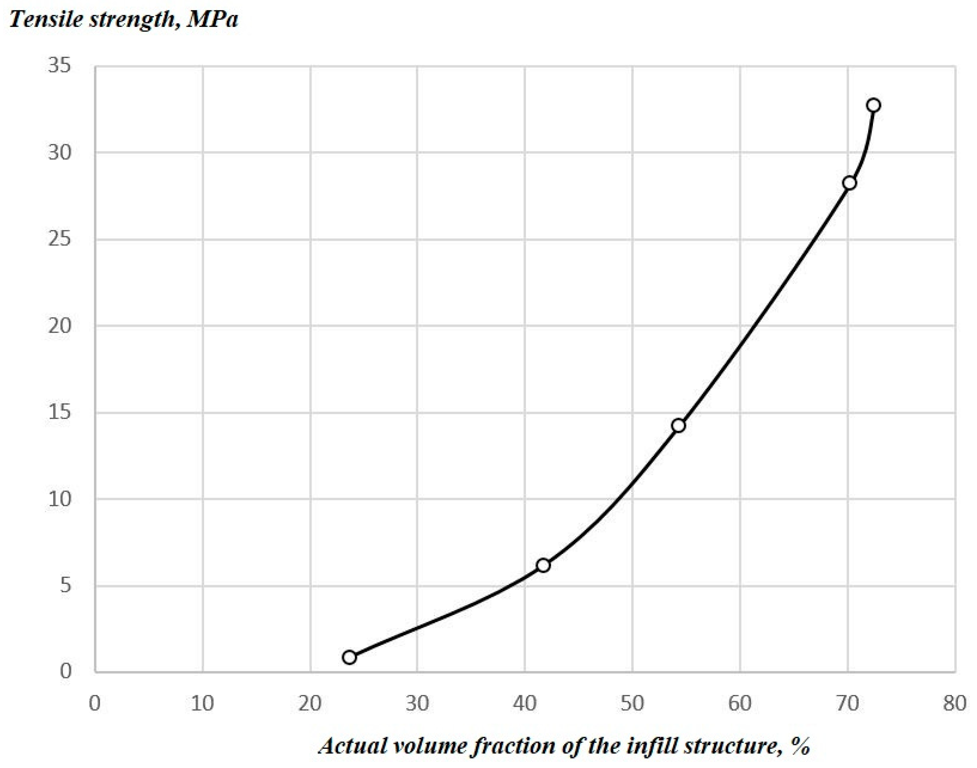
Average Theoretical Infill Volume Fraction А̅T%, %Average Actual Infill Volume fraction А̅ACT%, %Average Infill Tensile Strength σ̅BF, MPaAverage Weight in Relation to А̅T%Shell/Infill Ratio, %
2023.710.830.137175.73
4041.746.150.099015.77
6054.3514.200.0903866675.71
8070.2328.200.07599255.72
10072.4932.700.0628685.59

