AFM Characterization of Stir-Induced Micro-Flow Features within the AA6082-T6 BFSW Welds


University of Canterbury, Department of Mechanical Engineering, Christchurch 8140, New Zealand
*
Authors to whom correspondence should be addressed.
Technologies 2019, 7(4), 80; https://0-doi-org.brum.beds.ac.uk/10.3390/technologies7040080
Submission received: 4 October 2019
/
Revised: 5 November 2019
/
Accepted: 6 November 2019
/
Published: 7 November 2019
(This article belongs to the Special Issue Reviews and Advances in Materials Processing)
Abstract
:Bobbin Friction Stir Welding (BFSW) is a thermomechanical process containing severe plastic deformation by mechanical stirring and Dynamic Recrystallization (DRX) during recooling. Here we report the three-dimensional characteristics of the micro-flow patterns within the aluminium weld structure. The Surface topography observations by Atomic Force Microscopy (AFM) show the stirred-induced microstructural evolution where the rearrangement of dislocations at the sub-grain scale, and the subsequent High- and Low-Angle Grain Boundaries (HAGBs, LAGBs) exhibit specific alterations in grain size and morphology of the weld texture. The dislocations interaction in different regions of the weld structure also was observed in correlation to the thermomechanical behaviour of the BFSW process. These micro-flow observations within the weld breadth give a new insight into the thermomechanical characteristics of the FSW process during the stirring action where the plastic flow has a key role in the formation of the weld region distinct from the base metal.
1. Introduction
Bobbin Friction Stir Welding (BFSW) is a modified variant of Friction Stir Welding (FSW) [1] where the conventional tool is replaced by a bobbin-shaped double-sided configuration [2,3]. The rotating double-shoulder bobbin tool penetrates from the edge through the interface of the side-by-side plates, and mixes the materials into a butt-shaped joint [4,5,6]. The heat input [4] generated by the friction between the rotating tool and the workpiece plasticises the material from both sides of the interface, Advancing Side (AS) and Retreating Side (RS), and stirs them together to form a bonded structure [6]. The stirring action causes severe plastic deformation [7] at temperatures well below the usual melting point [4]. Hence, the process is suitable for the joining of low temperature deformable alloys [8]. Aluminium is an ideal material for successful processing under BFSW [2,9]. AA6082-T6 aluminium is an industrial marine grade alloy with good machinability which has recently become attractive for FSW processing [10,11,12,13,14].
To achieve a defect-free weld in FSW processes, the material flow regimes have a higher priority than the metallurgical details [15]. Therefore, it is necessary for the continued improvement of the BFSW process to determine the plastic flow patterns in the weld region, which has received minimal attention in the literature compared with metallurgical aspects.
The severe plastic deformation during friction stir welding is the main cause of alteration in grain size and morphology [16,17,18]. The sub-grain scale analysis of microstructure can elucidate the relationship between the microstructure and the thermomechanical nature of the FSW process, especially shearing and heat generation [19]. The deformation-induced texture varies across the weld, as the shear is the function of the distance of the stirred flow mass from the position of the rotating tool [16,20]. Hence, a better understanding of the grain structure has the potential to contribute to knowledge of the evolution of the thermomechanical mechanism.
This paper presents an innovative study of the three-dimensional topology of the material flow features of BFSW weld texture. By utilising the Atomic Force Microscopy (AFM), the surface topography in the microscopic scale reveals the flow-based characteristics of the weld arising from the stirring action as a severe plastic deformation. This has the potential to give a better understanding of the effect of the microscopic flow regimes on the thermomechanical properties of the BFSW weld texture.
In this work, a high-magnification microscopic measurement was used to observe how the micro-scale plastic deformation affects the microstructure. In this regard, microstructural changes with a focus on dislocation and flow-induced imperfections were analysed in diverse regions of the AA6082-T6 BFSW weld structure.
AFM analysis was used to identify the microscopic details of the weld texture. This provides a greater resolution—to the atomic level—compared to other microstructure measurements. More specifically, the dislocation network and the precipitation evolution within the weld texture can be observed with AFM.
2. Materials and Methods
The BFSW welding test was conducted with the AA6082-T6 aluminium alloy (Standard; EN AW-6082, ISO: Al Si1MgMn) rolled plates (Aalco Metals Ltd, UK) as the workpiece. The analysed chemical composition of the AA6082-T6 plate with the elemental details is listed in Table 1.
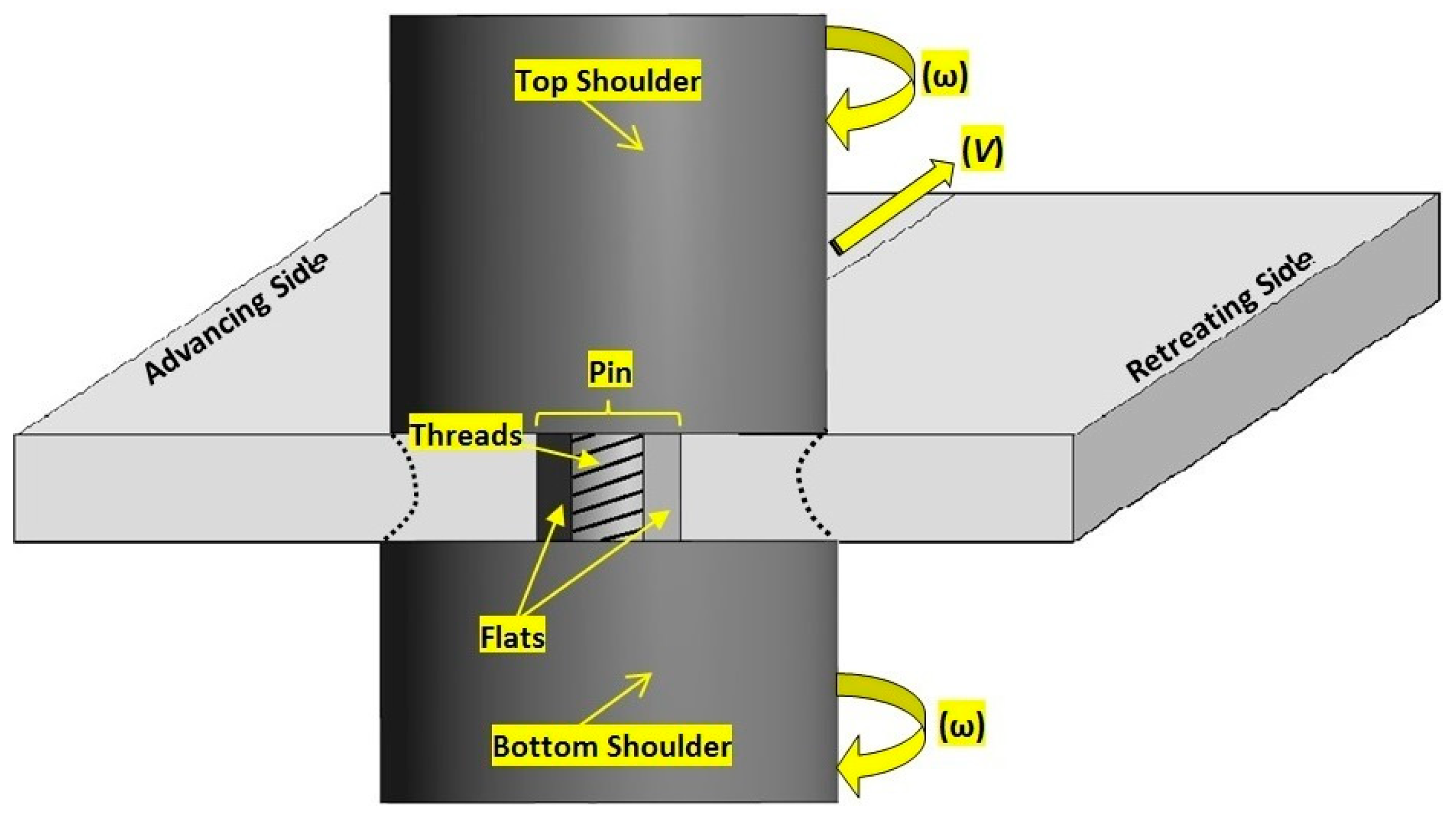
The weld samples were in a butt joint configuration comprising two similar plates (250 mm × 75 mm × 6 mm). The geometrically full-featured bobbin tool (included threads, flats and scrolls) was made of H13 tool steel with a hardness of 560 HV [5,6,21]. The schematic of the BFSW process is shown in Figure 1. The BFSW experiments were performed on a 3-axis CNC machining centre (2000 Richmond VMC Model, 600 Group brand, Sydney, Australia) with a Fanuc control unit and 14-horsepower spindle motor capacity. The simultaneous operation speeds consisted of spindle rotational speed (ω = 650 rpm), and weld travel rate (V = 400 mm/min). The direction of tool rotation was clockwise viewed from above.
The welded plates were cross-sectioned perpendicular to the weld-seam and were micro-polished to a mirror level, according to the standard metallographic preparation [22]. The samples then were etched by using of two modified reagents; (Reagent A: 2 mL HF + 2 mL HBF4 + 10 mL HNO3 + 20 mL CH3COOH + 33 mL H2O + 33 mL ethanol), and (Reagent B: 0.5 g (NH4)2MoO4 + 3.0 g NH4Cl + 1 mL HF + 18 mL HNO3 + 80 mL H2O) per [6,21]. Previous research has shown these etchants successfully delineate grain-boundary microstructure (Reagent A) and micro-flow patterns (Reagent B) [6,21]. Both reagents were used for similar etching time and temperature (90 s, 70 °C). For a better cleaning of the samples, the specimens were cleaned in the acetone bath (60 s, 18 °C), under an ultrasonic field of 40 KHz frequency. There is no known corrosive effect of acetone on this material.
To observe the macro-flow patterns within the BFSW weld structure, the etched samples were studied with a stereoscopic microscope (Olympus Metallurgical Microscope, Tokyo, Japan). Microscopic observations of the morphological features were conducted with an atomic force microscope (Veeco Digital Instruments Dimension 3100, from Bruker). The in-situ observations were done in contact mode, equipped with TAP300-G (PDMS imprint and replica) tips (BudgetSensors, USA), in dry conditions at ambient conditions (in air, at room temperature). Visualisation of the recorded mapping data and the three-dimensional topography analysis were processed by Gwyddion software (VERSION 2.45).
3. Results
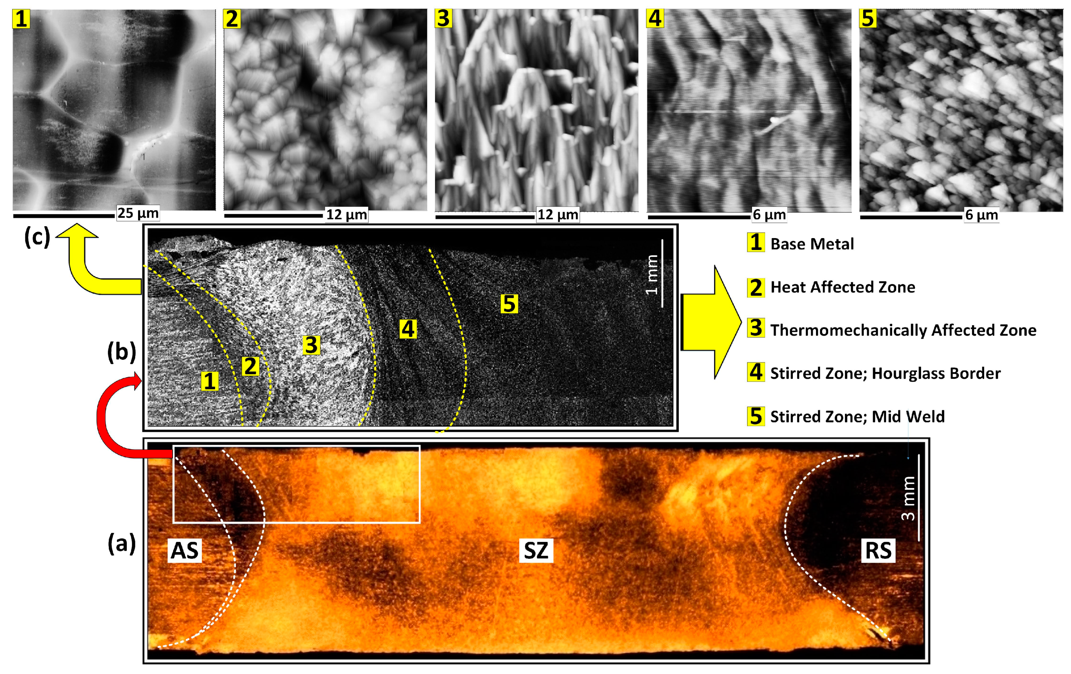
The macro-etched cross-section of the AA6082-T6 BFSW sample (etched by Reagent A) and micrographs of the relevant regions of the weld are shown in Figure 2. The microscopic images distinguish different morphological microstructure within the weld region from the Base Metal (BM), through to the transition region; Heat-Affected Zone (HAZ) and Thermomechanically Affected Zone (TMAZ), onwards to the Stirring Zone (SZ); flow arm patterns and middle of SZ. Compared to the base metal, the grain size in other regions of the weld shows an extensive grain refinement (reduction of grain size), and grain morphology.
The thermomechanical nature of the FSW process and the subsequent mechanical and thermal behaviours of the weld texture are believed to be the major activators for this microstructural evolution [21,23].
The AFM images of the weld region for the AA6082-T6 BFSW sample (etched by Reagent B) are demonstrated in Figure 3. After FSW treatment, there are microscopic changes that have taken place in different regions of the weld. The topographic features denote that the BM region (Zone 1) is smoother than the SZ (Zone 5), as well as the transition region at the AS/RS borders of the weld (Zones 3 and 4) where bulging lamellar microbands are evident.
The topographic features are interpreted as micro-flow patterns caused by plastic deformation during stirring. The peak-and-valley-like micropattern is apparent throughout the weld section. The figure also shows roughness and texture measures derived from the AFM process. Also given in the figure are descriptions of the grain morphology, and the evolution between these states.
The figure is left for inspection, but there are several broad comments to be made. Inspection of Zones 3 and 4 (SZ) (Figure 3) shows the dominance of wrinkled and linear features, unlike the other regions. Shear is only active in Zones 3 and 4: it does not exist in Zone 1 due to the T6 heat treatment, nor in Zone 2 since this is only affected by heat flux. The shear is less apparent in mid-SZ (Zone 5), which is consistent with a stress relieving process. The Dynamic Recrystallization (DRX) mechanism uses stored strain and heat to nucleate and recrystallize the microstructure into ultrafine grains, thereby erasing the shear bands that might otherwise be expected at this location [23].
We attribute the wrinkled features in Zones 3 and 4 to activation of dislocations due to shear. Zone 3 shows activation at main grain boundaries (High-Angle Grain Boundaries, HAGBs). There is possible evidence for accumulation of dislocations at grain boundaries. In contrast in Zone 4 the dislocations are arrays within the grains (Low-Angle Grain Boundaries, LAGBs) forming sub-grain boundaries. This rearrangement of dislocations is a typical thermomechanical characteristic of DRX.
The 3D topography maps and roughness profiles are not all the same scale, so care must be taken in interpretation of microscopic features. Overall it is apparent that there is a large change in microstructure from the bases metal to the other zones. The base metal is characterised, as expected, by large grains, absence of sub-grain boundaries, an evidence of precipitation inside the grains (because of the artificial ageing T6 cycle [21]). The AFM method is not ideally suited to the larger scale of 50μm where there may be voids and other surface defects that may introduce noise, hence caution is required in the interpretation of some the features at the larger scale. In the transition regions (Zones 2–4) there is evidence of similar roughness and size of features as quantified by the surface profile, but the 3D images show that the morphology is very different across these zones. In the stirred region (Zone 5) the roughness increases again. We believe this represents the density of grain boundaries, which is confirmed by the 3D image which shows more homogeneity and fineness in morphology.
The question might be asked whether the observations might be explained by corrosion (from the etching process) rather than shear. We suggest that the effects are not due to corrosion, for the following reasons. First, the same etchants have previously been shown not to result in corrosion artefacts [6,21]. Second, there is no evidence of pitting or a local depletion of the matrix phase around the precipitate particles, as might be expected from an aggressive etching. Neither do the local line scan profiles show any evidence of pitting or protrusions.
We propose the following interpretation of the process. The mechanical stirring induces a shearing distortion to the lattice of the plasticised mass. To mitigate this during DRX, the microshrinkage positions evolve to be at the location of the accumulated shear bands. The etching procedure leads to more clarity of these shearing microbands in 3D surface tomography scanned by the AFM (Zones 3 and 4 in Figure 3, apparent at nanoscale). It is evident that the etchant has a very different effect on the material in Zone 3, compared to the other zones. The grain boundaries are pronounced, creating a three-dimensional interconnected set of ridges. The inside of the grain is locally dissolved to a greater extent. We proposed that this arises from the selective etching features of the reagent solution, and we attribute this to the shear bands being more sensitive to this etchant. Specific sample preparation was used to avoid over-etching and production of corrosion artefacts.
The grain boundaries and morphologies were revealed because of different reactions of each region of the weld texture to the applied reagent. In this regards, the surface roughness measurements indicate the morphology alteration in different regions after etching [6,24]. All samples were treated with the same polishing and etching procedure.
The surface morphology in the flow arm region (Zone 4) is in agreement with the theory of the stirring action in the FSW process. We suggest that the periodicity of the flow arms (visible in Figure 2b) is caused by the rotary motion of the pin and its flats create. This causes the deposition, in the wake of the tool at the advancing side, of the parallel arm shapes [24,25,26,27]. The microstructure of Zone 4 (in Figure 3) was selected from one of these arms, and shows that the sub-grain boundaries (dark lines in Figure 3) are arranged parallel to the flow arm.
The actual roughness in the mid-SZ (Zone 5) was reduced, as the grain size has decreased compared to other regions of the weld. The micrograph shows larger variations, which is because of the higher magnification (smaller scale). The graph of surface roughness confirms that the distance of peaks and valleys as a measure of the surface roughness, is minimized for Zone 5.
3.1. Observation of Precipitate in Mid-SZ
The most plausible area for location of the precipitate particles is mid-SZ, which experiences a full DRX compared to other regions of the weld. However, from an imaging perspective there is a risk that the etching might eject the fine precipitates from their position within the microstructure. To minimise this risk, an unetched micropolished sample was used for the precipitation analysis. Furthermore, a variety of channelling modes were used for the AFM analysis.
In addition to the usual height channel mapping, frequency channel was used to provide a better resolution for the free edges of the precipitate in contrast with the matrix. Also to indicate the localized torsional stress field at the interface the precipitate-matrix phase, dissipation channel was used. These different channeling modes provide a more comprehensive observation.
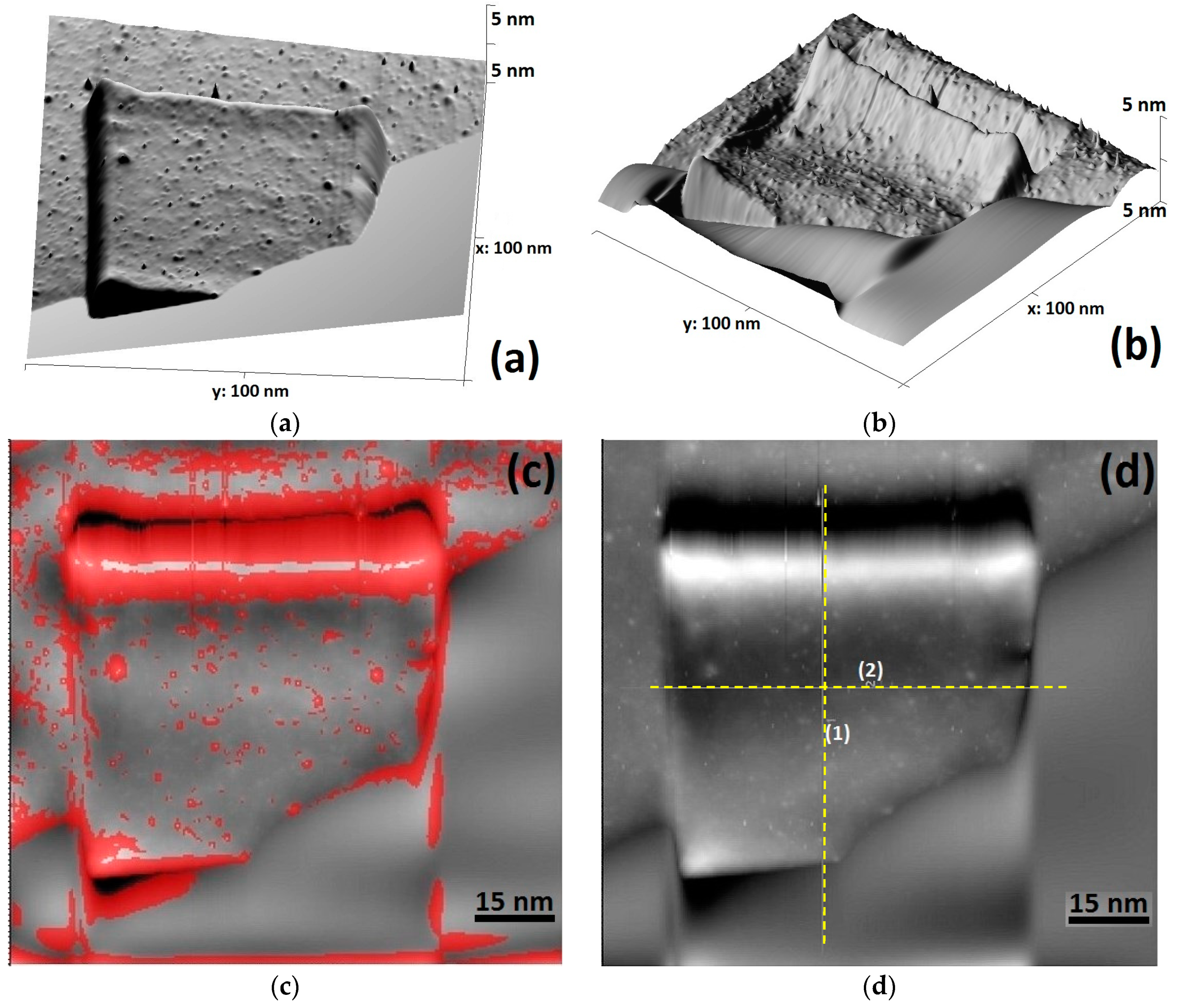
The micrographs (Figure 4a,d) and corresponding line profiles (Figure 4e) show an ultrafine particle of size less than 100 nm, a platelet morphology, and an embedment in the matrix. The height channel (Figure 4a) identifies a platelet shape particle without surface etching. The frequency channel (Figure 4b) provides better sharpness of contrast, and shows a localized cleaved pattern at the boundary of the precipitate-matrix. The dissipation channel (Figure 4c) also highlights the dissipated energy from the tapping tip of the AFM probe onto the sample surface. The red contrast, constructed at the interface of the precipitate-matrix phase, shows higher density of dissipated surface energy, attributed to the mechanical torsion at the border of the particle [28]. Frequency channel and dissipation channel both show that the border of the particle and the matrix possesses a distortion which is due to the embedment of the precipitate into the matrix [29,30]. Therefore, it is not an external particle or sediment at the surface.
In general, precipitation requires diffusion of alloying elements, and is function of time and temperature. DRX occurs within seconds during FSW, not enough time for diffusion to occur to produce precipitates and therefore the precipitating phase particles are expected to be ultrafine size [21,29], which indeed is demonstrated here (<100nm). The mechanism of precipitation here in FSW process is attributed to the severe shearing in the SZ and the heat. In the T6 artificially ageing process the cycle time is longer, the temperature is higher, and the process is closely controlled, resulting in control over the precipitates [21,29,30,31].
The observed platelet morphology has a maximum surface-to-volume, compared to other precipitate morphologies such as spherical or needle shaped. The platelet precipitation can occur in a relatively fast cooling rate at lower reaction temperatures [32,33]. Hence the observation of such a precipitate is consistent with the FSW condition. The density of precipitates was relatively low in the observed samples, less than might be expected from say fusion welding. This and the shape observed, suggest that the low temperature conditions in FSW result in a reduced precipitation.
3.2. Dislocations
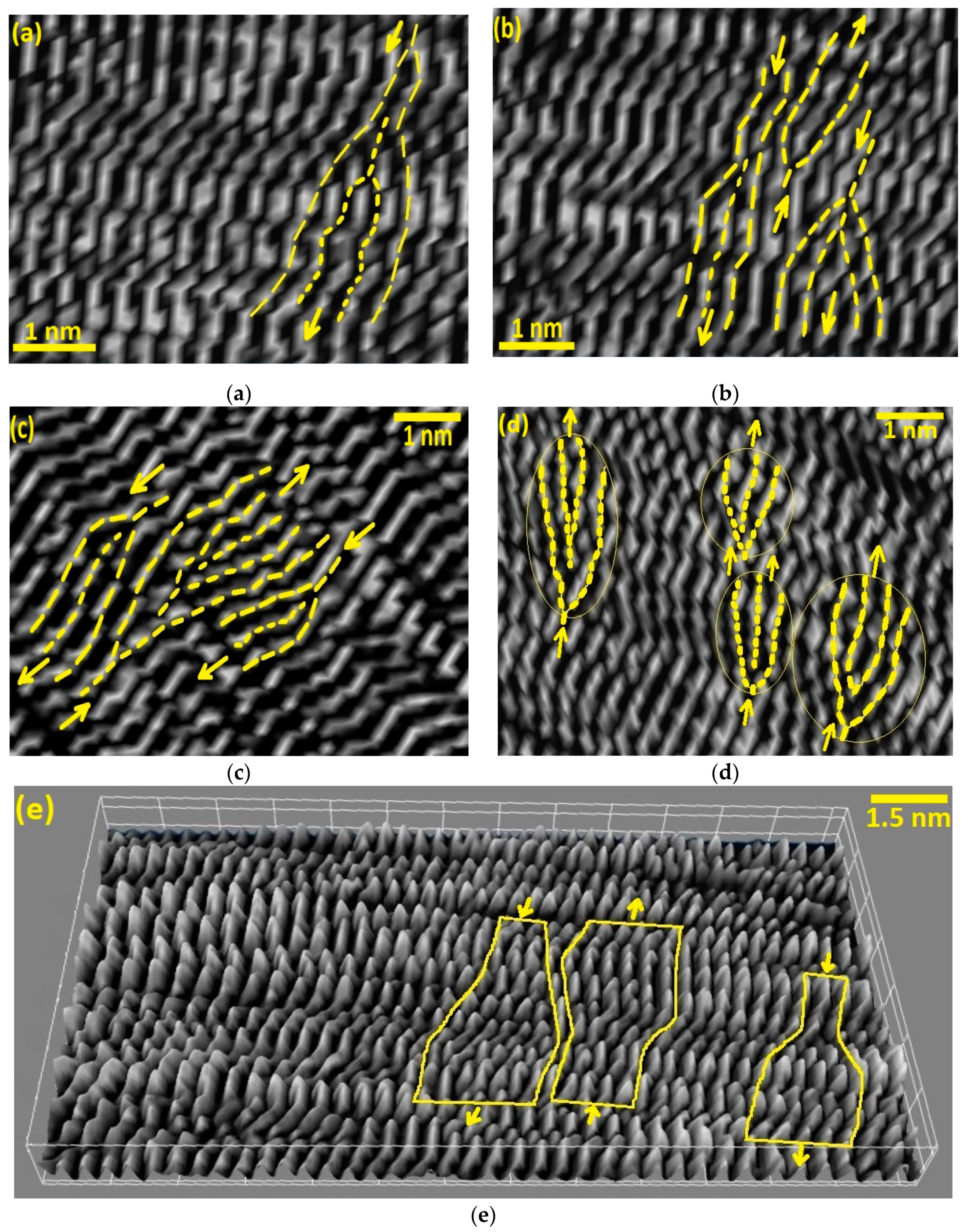
Dislocations are the out-of-position of atoms in the crystal structure of grains. The dislocation patterns within different region of the weld are shown in Figure 5. At this high magnification the misarrangement of the crystal layers becomes apparent. The edge dislocations are evident as the crystalline defect in the structure of the aluminium. In general, in polycrystalline structures under shearing (with an intrinsic misorientational angle >0.99) it is expected to observe dislocations as a structural defect through the lattice [19,23].
During plastic deformation and the subsequent DRX, dislocations are formed in specific preferential orientations within the crystal lattice. Furthermore, during the recooling, interaction and annihilation of dislocation results in rearrangement of dislocation arrays with different density in different regions. This can be related to the amount of the stored strain releasing during the recovery process, also the absorbed heat which is different for each region based on the distance from the frictional stirring action. The dislocations originate from the applied stress during stirring causing shear between the crystal layers. After stirring the DRX process involves movement of the dislocations. They may aggregate to form Low Angle Grain Boundaries (LAGBs) within the grains, or transfer to the grain boundaries and contribute to formation of new High Angle Grain Boundaries (HAGBs) and motion of grain boundaries [21,23].
4. Discussion
This paper describes joining of an aluminium alloy by bobbin FSW, and investigation of weld microstructural features using the Scanning Electron Microscopy (SEM) and AFM.
A key finding is the identification of three-dimensional micro-flow features with specific changes in grain size and morphology attributed to the stirring action. This has not previously been shown for friction stir welding, and the literature is silent on this aspect.
The AFM technique provides a visualization of features within grains, and by inference provides a record of the flow patterns occurring in a solid-state mechanical stirring by the bobbin-tool FSW [21,23,24]. The surface topographic features for different regions of the weld can also be measured quantitatively to compare the surface roughness corresponding to the shearing regime. A tentative flow-induced thermomechanical mechanism has been suggested for the SZ and the transition region, where the stirring-induced shearing stress affects the weld structure through the thermomechanical behaviour of the BFSW process.
A metallurgical transformation during the DRX process is identified by its effects on changing of grain size to ultrafine. This is evident as grain refinement by increasing density of grain boundaries (see Zone 5, Figure 3). Precipitation is also expected from DRX, but was not readily observed in etched surfaces. Dislocation interaction in the sub-grain scale was visible in the transition regions (Zones 3 and 4, Figure 3), as were HAGBs (Zone 3, Figure 3) and LAGBs (Zone 4, Figure 3). Hence the transformations preceding and caused by DRX have been observed.
4.1. Welding Parameters
The formation of the weld texture is because of the mechanical stirring action at the proximity of the rotating tool [16]. The welding process causes fragmentation, severe plasticizing, shearing deformation and frictional heating. Therefore, the welding process parameters (tool geometry and welding speeds) can have a major effect on the final microscopic characteristics of the weld texture [34,35]. The complexity of the tool geometry increases the frictional heating generated at the position of the tool-material, inducing more plastic flow through the softened mass [36].
Similarly, the welding speeds (ω, V) also can induce more fragmentation and subsequent plasticising, resulting in more strain and hence DRX during the stirring action [37].
All these can intensify the shearing flow during the mass transportation, and potentially elevate the generated heat useable for the DRX mechanism. Therefore, this might be worthwhile to investigate the role of optimised welding parameters in the microscopic evolution of the weld texture characteristics.
4.2. Limitations of this Work and Implications for Future Research
Our 3D visualization analysis of the microscopic features was limited to the ultrafine microstructural details at the scale of the grain structure of the weld. However, there are some macro-size defects such as tunnel void or cracks which may also have shearing-flow effects. In this regard, because of the limitation of the AFM analysis to ultrafine magnification, the macroscopic defects are better analysed by other microscopic measurements, such as optical microscopy or electron microscopy. Furthermore, fractography analysis could evaluate the crack propagation and failure mechanisms. The formation of these macro-size tunnel void and the micro-cracks adversely affects the strength of the final weld, therefore is unacceptable to industry users.
Another possible future research opportunity could be to use AFM to quantify the grain characteristics for the different weld regions. It may be possible to characterise the surface features, and quantify sub-grain boundaries, and mathematical link these metrics to the weld process. Complementary methods such as electron microscopy (e.g., Electron Backscatter Diffraction (EBSD) and Transmission Electron Microscopy (TEM)) might be considered.
5. Conclusions
This research determined a physical measurement for describing micro-flow features within the BFSW weld breadth using a three-dimensional surface topography by AFM. It was revealed that the mechanical stirring was associated with complex flow regimes through the stirring zone, also induced shear features at the microscale. These add stored strain to the texture which appears to lead to physical alteration in recrystallization of the weld texture during the post-welding cooling. Therefore, different regions of the BSFW (SZ, TMAZ, HAZ) are identified in different microscopic patterns corresponding to thermomechanical behaviour of the weld.
A key outcome is the use of AFM to better understand the grain structure of the AA6082-T6 material under solid-state friction-stir welding. This is an important industrial material but its thermomechanical behaviour has been poor in this type of welding. The results of this paper elucidate the grain boundaries and precipitates, and thereby show the results of the thermomechanical processes. AFM has been shown to be a useful tool to better understand the gain boundary engineering, dislocation behaviour, and precipitation of this material.
Author Contributions
Conceptualization, A.T. and D.J.P.; Methodology, A.T.; Validation, A.T.; Formal analysis, A.T. and D.J.P.; Writing—original draft preparation, A.T.; Writing—review and editing, A.T. and D.J.P.; Supervision, D.J.P. and D.C.
Funding
This research received no external funding.
Conflicts of Interest
The authors declare no conflict of interest.
References
- Thomas, W.; Nicholas, E.; Needham, J.; Murch, M.; Temple-Smith, P.; Dawes, C. Friction Stir Butt Welding. International Patent No. PCT/GB92/02203 27 November 1991. [Google Scholar]
- Threadgill, P.L.; Ahmed, M.; Martin, J.P.; Perrett, J.G.; Wynne, B.P. The use of bobbin tools for friction stir welding of aluminium alloys. In Materials Science Forum; Trans Tech Publications: Zurich, Switzerland, 2010; pp. 1179–1184. [Google Scholar]
- Sued, M.; Pons, D.; Lavroff, J.; Wong, E.-H. Design features for bobbin friction stir welding tools: Development of a conceptual model linking the underlying physics to the production process. Mater. Des. 2014, 54, 632–643. [Google Scholar] [CrossRef]
- Hilgert, J.; Schmidt, H.; Dos Santos, J.; Huber, N. Thermal models for bobbin tool friction stir welding. J. Mater. Process. Technol. 2011, 211, 197–204. [Google Scholar] [CrossRef] [Green Version]
- Tamadon, A.; Pons, D.; Sued, K.; Clucas, D. Formation mechanisms for entry and exit defects in bobbin friction stir welding. Metals 2018, 8, 33. [Google Scholar] [CrossRef]
- Tamadon, A.; Pons, D.; Sued, K.; Clucas, D. Development of metallographic etchants for the microstructure evolution of a6082-t6 bfsw welds. Metals 2017, 7, 423. [Google Scholar] [CrossRef]
- Hilgert, J.; Hütsch, L.L.; dos Santos, J.; Huber, N. Material flow around a bobbin tool for friction stir welding. In Proceedings of the COMSOL Conference, Paris, France, 29–30 October 2010. [Google Scholar]
- Wang, F.; Li, W.; Shen, J.; Wen, Q.; dos Santos, J. Improving weld formability by a novel dual-rotation bobbin tool friction stir welding. J. Mater. Sci. Technol. 2018, 34, 135–139. [Google Scholar] [CrossRef]
- Shen, J.; Wang, F.; Suhuddin, U.F.; Hu, S.; Li, W.; Dos Santos, J.F. Crystallographic texture in bobbin tool friction-stir-welded aluminum. Metall. Mater. Trans. A 2015, 46, 2809–2813. [Google Scholar] [CrossRef]
- Huang, Y.; Wan, L.; Lv, S.; Feng, J. Novel design of tool for joining hollow extrusion by friction stir welding. Sci. Technol. Weld. Join. 2013, 18, 239–246. [Google Scholar] [CrossRef]
- Węglowska, A. The use of a bobbin tool in the friction stir welding of plates made of aluminium alloy en aw 6082–t6. Biuletyn Instytutu Spawalnictwa Gliwicach 2018, 62. [Google Scholar] [CrossRef]
- Wan, L.; Huang, Y.; Guo, W.; Lv, S.; Feng, J. Mechanical properties and microstructure of 6082-t6 aluminum alloy joints by self-support friction stir welding. J. Mater. Sci. Technol. 2014, 30, 1243–1250. [Google Scholar] [CrossRef]
- Chen, S.; Lu, A.; Yang, D.; Lu, S.; Dong, J.; Dong, C. Analysis on flow pattern of bobbin tool friction stir welding for 6082 aluminum. In Proceedings of the 1st International Joint Symposium on Joining and Welding, Osaka, Japan, 6–8 November 2013; Elsevier: Amsterdam, The Netherlands, 2013; pp. 353–358. [Google Scholar]
- Wan, L.; Huang, Y.; Lv, Z.; Lv, S.; Feng, J. Effect of self-support friction stir welding on microstructure and microhardness of 6082-t6 aluminum alloy joint. Mater. Des. 2014, 55, 197–203. [Google Scholar] [CrossRef]
- Hilgert, J.; Dos Santos, J.F.; Huber, N. Shear layer modelling for bobbin tool friction stir welding. Sci. Technol. Weld. Join. 2012, 17, 454–459. [Google Scholar] [CrossRef] [Green Version]
- Dialami, N.; Cervera, M.; Chiumenti, M. Effect of the tool tilt angle on the heat generation and the material flow in friction stir welding. Metals 2019, 9, 28. [Google Scholar] [CrossRef]
- Egea, A.S.; Rodriguez, A.; Celentano, D.; Calleja, A.; de Lacalle, L.L. Joining metrics enhancement when combining fsw and ball-burnishing in a 2050 aluminium alloy. Surf. Coat. Technol. 2019, 367, 327–335. [Google Scholar] [CrossRef]
- He, X.; Gu, F.; Ball, A. A review of numerical analysis of friction stir welding. Prog. Mater. Sci. 2014, 65, 1–66. [Google Scholar] [CrossRef] [Green Version]
- Tayon, W.A.; Domack, M.S.; Hoffman, E.K.; Hales, S.J. Texture evolution within the thermomechanically affected zone of an al-li alloy 2195 friction stir weld. Metall. Mater. Trans. A 2013, 44, 4906–4913. [Google Scholar] [CrossRef]
- Fonda, R.; Bingert, J. Texture variations in an aluminum friction stir weld. Scr. Mater. 2007, 57, 1052–1055. [Google Scholar] [CrossRef]
- Tamadon, A.; Pons, D.; Sued, K.; Clucas, D. Thermomechanical grain refinement in aa6082-t6 thin plates under bobbin friction stir welding. Metals 2018, 8, 375. [Google Scholar] [CrossRef]
- Vander Voort, G.F.; Lampman, S.R.; Sanders, B.R.; Anton, G.J.; Polakowski, C.; Kinson, J.; Muldoon, K.; Henry, S.D.; Scott Jr, W.W. Asm handbook. Metallogr. Microstruct. 2004, 9. Available online: https://www.asminternational.org/documents/10192/1849770/06044G_Frontmatter.pdf (accessed on 11 November 2019).
- Tamadon, A.; Pons, D.J.; Clucas, D.; Sued, K. Texture evolution in aa6082-t6 bfsw welds: Optical microscopy and ebsd characterisation. Materials 2019, 12, 3215. [Google Scholar] [CrossRef] [PubMed]
- Tamadon, A.; Pons, D.J.; Clucas, D.; Sued, K. Internal material flow layers in aa6082-t6 butt-joints during bobbin friction stir welding. Metals 2019, 9, 1059. [Google Scholar] [CrossRef]
- Tamadon, A.; Pons, D.; Sued, M.; Clucas, D.; Wong, E. Preparation of plasticine material for analogue modelling. In Proceedings of the International Conference on Innovative Design and Manufacturing (ICIDM2016), Auckland, New Zealand, 24–26 January 2016. [Google Scholar]
- Tamadon, A.; Pons, D.; Sued, M.; Clucas, D.; Wong, E. Analogue modelling of bobbin tool friction stir welding. In Proceedings of the International Conference on Innovative Design and Manufacturing (ICIDM2016), Auckland, New Zealand, 24–26 January 2016. [Google Scholar]
- Sued, M.; Tamadon, A.; Pons, D. Material flow visualization in bobbin friction stir welding by analogue model. Proc. Mech. Eng. Res. Day 2017, 2017, 368–369. [Google Scholar]
- Barényi, I.; Eckert, M.; Majerík, J.; Bezecný, J. Afm and nanoindentation study of selected aluminium alloys. Zeszyty Naukowe Politechniki Rzeszowskiej. Mechanika 2018, 143–152. [Google Scholar] [CrossRef]
- Chrominski, W.; Lewandowska, M. Precipitation phenomena in ultrafine grained al–mg–si alloy with heterogeneous microstructure. Acta Mater. 2016, 103, 547–557. [Google Scholar] [CrossRef]
- Marioara, C.; Andersen, S.; Jansen, J.; Zandbergen, H. Atomic model for gp-zones in a 6082 al–mg–si system. Acta Mater. 2001, 49, 321–328. [Google Scholar] [CrossRef]
- Dadbakhsh, S.; Karimi Taheri, A. Study on static strain aging of 6082 aluminium alloy. Mater. Sci. Technol. 2010, 26, 169–175. [Google Scholar] [CrossRef]
- Gubicza, J.; Krállics, G.; Schiller, I.; Malgyn, D. Evolution of the microstructure of al 6082 alloy during equal-channel angular pressing. In Materials Science Forum; Trans Tech Publications: Zurich, Switzerland, 2005; pp. 453–458. [Google Scholar]
- Marioara, C.; Andersen, S.; Jansen, J.; Zandbergen, H. The influence of temperature and storage time at rt on nucleation of the β phase in a 6082 al–mg–si alloy. Acta Mater. 2003, 51, 789–796. [Google Scholar] [CrossRef]
- Fonda, R.; Knipling, K.; Bingert, J. Microstructural evolution ahead of the tool in aluminum friction stir welds. Scr. Mater. 2008, 58, 343–348. [Google Scholar] [CrossRef]
- Fonda, R.; Knipling, K. Texture development in friction stir welds. Sci. Technol. Weld. Join. 2011, 16, 288–294. [Google Scholar] [CrossRef]
- Fuse, K.; Badheka, V. Bobbin tool friction stir welding: A review. Sci. Technol. Weld. Join. 2019, 24, 277–304. [Google Scholar] [CrossRef]
- Fonda, R.; Reynolds, A.; Feng, C.; Knipling, K.; Rowenhorst, D. Material flow in friction stir welds. Metall. Mater. Trans. A 2013, 44, 337–344. [Google Scholar] [CrossRef]
Figure 1.
Schematic of the Bobbin Friction Stir Welding process; Bobbin-Tool in interaction with the workpiece as the substrate.
Figure 1.
Schematic of the Bobbin Friction Stir Welding process; Bobbin-Tool in interaction with the workpiece as the substrate.

Figure 2.
Macroscopic and microscopic features of the BFSW weld for the etched cross-section of the AA6082-T6 plate (reagent A); (a) Macro-etched cross-section of the AA6082-T6 sample, representative of the hourglass shaped weld structure, (b) the selected region from AS region at Figure 2a, in higher magnification, distinguishing five different regions for the weld breadth, (c) SEM images of 5 different regions of the weld texture, demonstrated in Figure 2b. (AS; Advancing Side, RS; Retreating Side, BM; Base Metal, SZ; Stirring Zone).

Figure 3.
3D topographic AFM images of different regions of the BFSW weld texture measured by the relevant height profiles of the surface roughness and the in detail explanation of the morphological evolution of the microstructure.
Figure 3.
3D topographic AFM images of different regions of the BFSW weld texture measured by the relevant height profiles of the surface roughness and the in detail explanation of the morphological evolution of the microstructure.
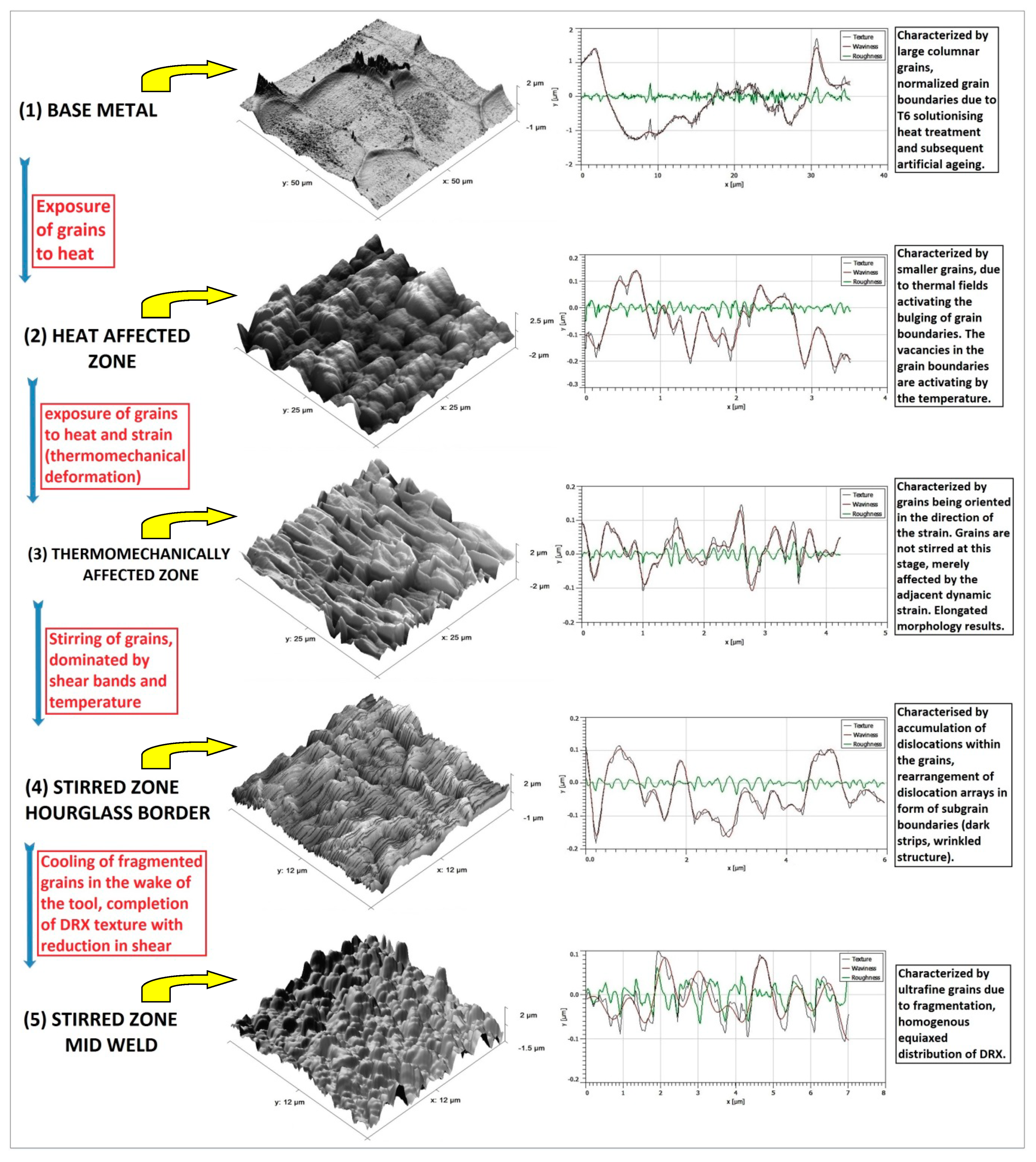
Figure 4.
Selected surface area demonstrating the platelet shape precipitate, scanned by AFM using different channel modes; (a) height channel exposure, (b) frequency channel, (c) dissipation channel, (d) phase contrast micrograph, (e) line profiles corresponding to the surface roughness of the particle.


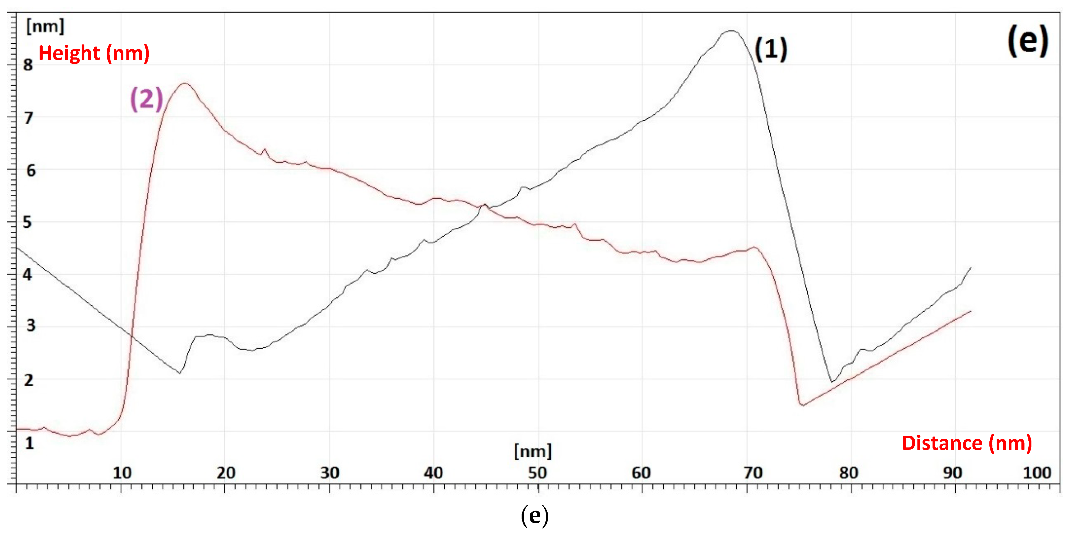
Figure 5.
Stripped patterns of the crystalline lattice of AA6082-T6 BFSW weld; (a–e) The landmarks indicates some of edge dislocations between the lattice planes (crystal layers), in different regions of the weld; (a) BM, (b) HAZ, (c) TMAZ, (d) Hourglass-border of SZ. (e) AFM map with very high resolution crystal structure with corresponding edge Dislocations (mid-SZ).


Table 1.
Chemical composition of the AA6082-T6 aluminium alloy, in elemental detail (wt.%).
| AA6082-T6 Aluminium Alloy | |
|---|---|
| Chemical Element | % Present |
| Silicon (Si) | (0.70–1.30) |
| Magnesium (Mg) | (0.60–1.20) |
| Manganese (Mn) | (0.40–1.00) |
| Iron (Fe) | (0.0–0.50) |
| Chromium (Cr) | (0.0–0.25) |
| Zinc (Zn) | (0.0–0.20) |
| Titanium (Ti) | (0.0–0.10) |
| Copper (Cu) | (0.0–0.10) |
| Other (Each) | (0.0–0.05) |
| Other (total) | (0.0–0.15) |
| Aluminium (Al) | Balance |
© 2019 by the authors. Licensee MDPI, Basel, Switzerland. This article is an open access article distributed under the terms and conditions of the Creative Commons Attribution (CC BY) license (http://creativecommons.org/licenses/by/4.0/).
Share and Cite
MDPI and ACS Style
Tamadon, A.; Pons, D.J.; Clucas, D. AFM Characterization of Stir-Induced Micro-Flow Features within the AA6082-T6 BFSW Welds. Technologies 2019, 7, 80. https://0-doi-org.brum.beds.ac.uk/10.3390/technologies7040080
AMA Style
Tamadon A, Pons DJ, Clucas D. AFM Characterization of Stir-Induced Micro-Flow Features within the AA6082-T6 BFSW Welds. Technologies. 2019; 7(4):80. https://0-doi-org.brum.beds.ac.uk/10.3390/technologies7040080
Chicago/Turabian StyleTamadon, Abbas, Dirk J. Pons, and Don Clucas. 2019. "AFM Characterization of Stir-Induced Micro-Flow Features within the AA6082-T6 BFSW Welds" Technologies 7, no. 4: 80. https://0-doi-org.brum.beds.ac.uk/10.3390/technologies7040080
Note that from the first issue of 2016, this journal uses article numbers instead of page numbers. See further details here.